


00P3DG700ZXSEA1
Network Video Storage
User’s Manual
Version 1.1
NVS User’s Manual
2
Caution and Preventive Tips
• Switch the 115/230V selector to your local voltage standard
• Handle with care, do not drop the unit
• Mount the unit in an equipment rack or place it on a solid, stable surface.
• Indoor use only. Do not place the unit in a humid, dusty, oily, or smoky site.
• Do not place it in an area with poor ventilation or in an area close to fire or other sources of
heat. Doing so may damage the unit as well as cause fire or an electric shock.
• When cleaning is necessary, shut down the system and unplug the unit from the outlet
before uncovering the top cover. Do not use liquid cleaners o r aerosol cleaners. Use only a
damp cloth for cleaning.
• Always shut down the system prior connecting or disconnecting accessories, with the
exception of USB devices.
This symbol intends to alert the user to the presence of important operating and
maintenance (servicing) instructions in the literature accompanying the
appliance.
This symbol intends to alert the user to the presence of unprotected “Dangerous
Voltage” within the product’s enclosure that may be strong enough to cause a
risk of electric shock.

NVS User’s Manual
3
Important Information
Before proceeding, please read and observe all instructions and warnings in this manual.
Retain this manual with the original bill of sale for future reference and, if necessary, warranty
service. When unpacking your unit, check for missing or damaged items. If any item is missing,
or if damage is evident, DO NOT INSTALL OR OPERATE THIS PRODUCT. Contact your
dealer for assistance.
Rack Mounting
Consult with the supplier or manufacturer of your equipment rack for the proper hardware and
procedure of mounting this product in a safe fashion. Avoid uneven loading or mechanical
instability when rack-mounting units. Make sure that units are installed to get enough airflow
for safe operation. The maximum temperature for rack-mounted units is 40 °C. Check product
label for power supply requirements to assure that no overloading of supply circuits or over
current protection occurs. Mains grounding must be reliable and uncompromised by any
connections.

NVS User’s Manual
4
Table of Contents
1. Overview ....................................................................................................................... 6
2. System Installation ....................................................................................................... 7
2.1 Unit Position ........................................................................................................... 7
2.2 Device Connection ................................................................................................. 7
2.3 Rear Panel Connectors .......................................................................................... 8
2.4 Compatible IP Cameras ......................................................................................... 9
3. General System Setup ............................................................................................... 10
3.1 Front Panel Introduction ....................................................................................... 10
3.2 Power On / Shutdown / Reboot ............................................................................ 11
3.3 Network Configuration .......................................................................................... 1 1
3.4 OSD Menu of the NVS ......................................................................................... 12
4. Remote Monitoring Software ................................................................................ 13
4.1 System Requirement ............................................................................................ 13
4.2 Software Installation ............................................................................................. 14
4.2.1 Internet Setting .......................................................................................... 14
4.2.2 Software Installation .................................................................................. 16
4.2.3 Software Upgrade ...................................................................................... 16
4.3 Login / Logoff ........................................................................................................ 17
4.4 Live Monitoring ..................................................................................................... 18
4.4.1 Display Mode ............................................................................................. 18
4.4.2 IP Dome Camera Control........................................................................... 18
4.4.3 Digital Zoom ............................................................................................... 19
4.5 Instant Recording ................................................................................................. 20
4.6 Video Playback ..................................................................................................... 20
4.6.1 Remote Video Playback ............................................................................ 21
4.6.2 Local Video Playback ................................................................................ 21
4.6.3 Digital Signature Verification ...................................................................... 22
4.6.4 Playback Controls ...................................................................................... 22
4.7 OSD Configuration Menu ..................................................................................... 23
4.7.1 System Setup ............................................................................................ 23
4.7.2 Camera Setup............................................................................................ 25
4.7.3 Record Setup ............................................................................................. 27
4.7.4 Event Setup ............................................................................................... 28
4.7.5 Database Setup ......................................................................................... 30
4.7.6 Configuration ............................................................................................. 31
4.7.7 PoE Setup ................................................................................................. 31
4.7.8 Shutdown ................................................................................................... 32

NVS User’s Manual
5
4.8 Event List Search ................................................................................................. 32
4.9 Snapshot .............................................................................................................. 33
4.10 Health Status of HDD ........................................................................................... 33
4.11 Main/Dual Stream ................................................................................................. 33
4.12 Remote Monitoring Software Troubleshooting ...................................................... 34
Appendix A: Recommended HDDs ................................................................................ 35
Appendix B: NVS OSD Menu Tree .................................................................................. 36

NVS User’s Manual
6
1. Overview
The Network Video Storage (NVS) is a premium network video recorder
supporting IP camera Plug & Play automatic installation, and up to 16 ports
PoE switch. The NVS is an ideal edge recording solution for system
integrators and installers applicable from small convenience stores and
merchandise stores to medium-sized surveillance systems and projects.
With Plug & Play system, the NVS provides users up to 16 channels of IP
cameras connection without network, user name, password and other
complicated settings. Embedded with Power over Ethernet switch, the NVS is
perfect edge storage, allowing users to reduce expenditure on network
bandwidth and equipment, camera power supplies, cabling and installation.
Integrating complete recording setup interface makes database management
of the NVS easy, instant and flexible. Additionally, the central management
software provides NVS users a scalable solution for project applications.
Moreover, users are able to monitor remotely by using the Mobile View
software for smart phones.

NVS User’s Manual
7
2. System Installation
The notices and introduction on system installation will be described
particularly in this chapter. Please follow the description to operate the unit.
In order to prevent the unit from data loss and system damage that caused by
a sudden power fluctuation, use of an Uninterruptible Power Supply (UPS) is
highly recommended.
2.1 Unit Position
Firstly, note to position / mount the NVS in a proper place and be sure to keep
the unit power off before making any connections. The placed location should
avoid hindering or blocking the unit from airflow. Enough airflow is needed to
protect the unit from overheating. The maximum tolerable temperature of
operating environment is 40°C.
The unit utilizes heat-conducting techniques to transfer internal heat to the
case, especially to the bottom side of the unit.
NOTE: Be sure the rubber feet are not removed, and always leave a
space for air ventilation at the unit’s bottom side.
2.2 Device Connection
This section lists some notices that should be given before making any
connections to the NVS.
Connecting Required Devices
Before powering on the unit, cameras and internet should be connected to the
unit for basic operation. If needed, connect an e-SATA device to expand the
storage size.
Connecting Short-term Device
If any short-term devices shall be installed to the NVS as parts of the unit
system, such as USB ThumbDrive or any USB devices, etc., make sure those
devices are connected only after the unit is powered on. The reason is
because the NVS can recognize external devices only after the power-on
process is done completely.
NVS User’s Manual
8
2.3 Rear Panel Connectors
There are various connectors on the rear panel for the NVS installations. The
connectors are described as the following.
Power Jack
Connect the power supply cord shipped with the NVS.
NOTE: Use of other power supply cords may
cause overloading.
e-SATA (Reserved)
Users can connect an e-SATA storage device via this
port to expend HDD capacity of the NVS.
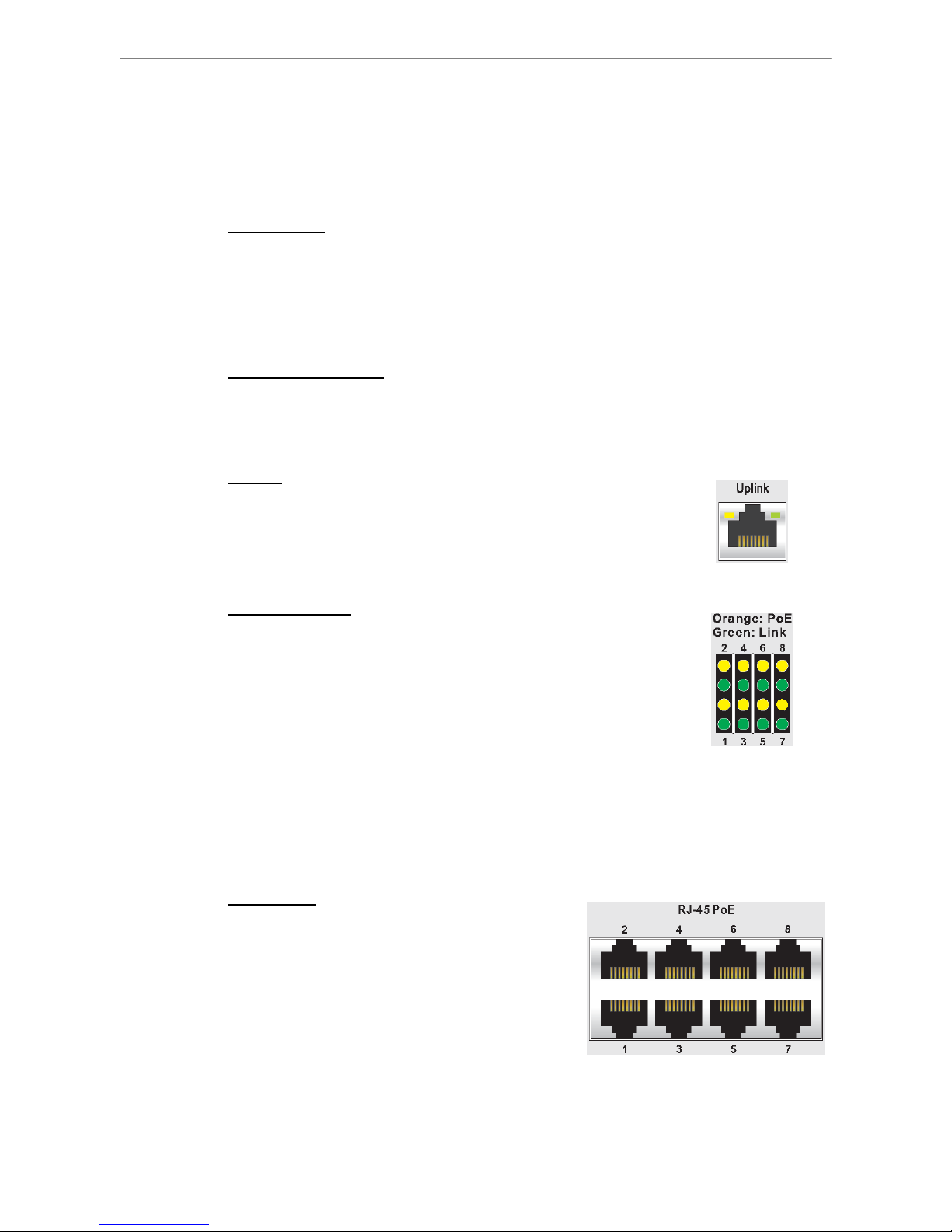
Uplink
Connect to a LAN port via a RJ-45 cable and the NVS
are connected to the Ethernet. Then users can connect
to the NVS via the internet browser.
LED Indication
Each IP camera has two corresponding LEDs:
1. The lightened orange LEDs represent the IP camera
is connected and power is supplied via PoE. When a
LED is off, either the IP camera is not connected or
its power supply is separately connected.
2. The blinking green LEDs represent data
transmission goes from the IP cameras to the NVS.
When a LED is not on, that means the IP camera is
not connected.
RJ-45 PoE
The NVS provides RJ-45 ports that support
Power over Ethernet (PoE). IP cameras can
be connected via just one Ethernet cable,
without the need of power cable connection.

NVS User’s Manual
9
2.4 Compatible IP Cameras
The NVS is designed with dual stream function that provides two suitable
streaming types respectively for Live display and recording videos. The
compression mode for Live display is H.264 with D1 resolution in multiple
channels and with HD in single channel. For recording videos, the
compression mode will be H.264 with HD resolution.
NOTE: Before connecting any IP cameras, their IP address has to be
set to default or static, otherwise the NVS will not be able to recognize
the existence of the IP cameras.
When an IP camera is connected, the NVS will automatically setup the dual
streams of the IP camera to D1+H.264 for multiple channel Live display and
HD+H.264 for single channel Live display and recording videos. Therefore,
the IP cameras must support dual stream function. Currently, the only
supported IP cameras are Nx Series models with software version released
later than June.
NOTE: After the IP cameras are connected, it takes 30 to 60 seconds
for the NVS to adjust the dual streaming setting and retrieving videos
from the IP cameras.
Port Forwarding
Thanks to the port forwarding function, users can directly connect IP cameras
by adding ports at the end of the NVS’s IP address. The ports for channels 1
to 8 are respectively 81 to 88. For example, if users wish to directly connect
the IP camera at channel 5, the connecting IP address should be entered as
“http://NVS’s IP Address:85”.
NOTE: if by any chance users will change the streaming setting of the
IP cameras, be sure to select H.264 only. Any other compression mode
will be considered as video loss.

NVS User’s Manual
10
3. General System Setup
Before operating the NVS, some general configuration should be setup first.
The following subsections will introduce function keys on the front panel and
general configuration of the NVS.
The LCD display on the front panel will show current date/time and IP address
plus unit name of the NVS at normal mode, as shown below. The LCD display
will also show the menu items while users are accessing the OSD menu via
the function keys.
[192.168.7.84]
2011/09/09 04:31:22 PM
3.1 Front Panel Introduction
The front panel controls enable users to configure network settings, verify
system information, software upgrade, etc. Please refer to the Setup Guide
for the graphical illustration of function keys.
POWER Key
• After power cord is correctly connected, press this key to switch power on.
• Press and hold this key to quick shutdown the NVS.
Direction Keys
The direction keys are used to move the cursor to previous or next fields. To
change the value in the selected field, press UP / DOWN keys.
ENTER
• At normal mode, press this key to enter the OSD menu.
• In OSD menu or selection interface, press this key to make selection or
save settings.
ESC
Press this key to cancel or exit.
USB 2.0 Port
The USB 2.0 port allows users to connect an external USB ThumbDrive to the
unit, so that users can perform software upgrade.

NVS User’s Manual
11
3.2 Power On / Shutdown / Reboot
If the NVS must be shutdown for any reason, please use the proper shutdown
and power on procedures to avoid damaging the NVS.
Power On the Unit:
Check the type of power source before plug in the power cord to the NVS (the
acceptable power input is between AC110V ~ AC240V), and power on the
unit via pressing the POWER key on the front panel.
Shutdown the Unit:
Press ENTER to access the OSD menu and select <Shutdown>. Then press
ENTER again and select <Yes> to confirm shutting down the unit. Do not
remove the power cord before the LCD display is off. The LED of the POWER
key will blink if the power cord is not detached.
NOTE: Users can also press and hold the POWER key to quick
shutdown the NVS.
Reboot the Unit:
Press ENTER to access the OSD menu and select <Reboot>. Then press
ENTER again and select <Yes> to start rebooting the unit.
3.3 Network Configuration
Before users can start using the NVS, its network settings have to be defined
first. Press ENTER to access the OSD menu and select <System Setup> Æ
<Network Setup> Æ <Ethernet1>. Then users can setup connection type, IP,
Netmask, and Gateway of the NVS. There are two different type of setting:
1. For DHCP users, set <Connection Type> to <DHCP>. Then IP,
Netmask, and Gateway will be automatically retrieved from network
servers. The settings are dynamic thus will change from time to time.
2. For Non-DHCP users, set <Connection Type> to <Static>. IP, Netmask,
and Gateway must be entered manually. Please obtain the information
from the network service provider.
To change IP, Netmask, and Gateway, press UP/DOWN keys and press
ENTER to select the setting item. Then use LEFT/RIGHT keys to access
each section of the value, and change the value using UP/DOWN keys.
 Loading...