

Page 1
Atlas IV
68-Pin Jumper Settings
68-Pin Jumper Settings
The following describes the jumper options and settings available on the Maxtor®
Atlas™ IV disk drive. For more detail on jumper definitions; please refer to the jumper
definition section.
The Atlas IV was developed by the Quantum Corporation prior to its merger with Maxtor.
Delay Spin (DS)
Enable Delay Spin
Disable Delay Spin
SCSI ID (A3, A2, A1, A0)
Set drive SCSI ID
Jumper across pins 11-12
No jumper across pins 11-12
See ID settings table below
1 of 1
Page 2

Atlas IV
68-Pin Jumper Settings
Force SE (SE)
Force Single Ended Mode
LVD Operation
No Wide (NW)
Enable Narrow Mode
Enable Wide Mode
Jumper across pins 13-14
No jumper across pins 13-14
Jumper across pins 23-24
No jumper across pins 23-24
Stagger Spin
Enable stagger spin
Disable stagger spin
Termination Power
Enable Termination Power
Disable Termination Power
Write Protect
Enable Write Protection
Disable Write Protection
Termination Note
Jumper across pins 21-22
No jumper across pins 21-22
Jumper across pins 27-28
No jumper across pins 27-28
Jumper across pins 19-20
No jumper across pins 19-20
The Atlas IV wide disk drive is manufactured as an Ultra2 Multi-Mode LVD device only.
This drive does not provide for onboard SCSI bus termination. Refer to your system or
SCSI controller documentation regarding recommendations on SCSI bus termination.
Jumper Location
2 of 2
Page 3
Atlas IV
68-Pin Jumper Settings
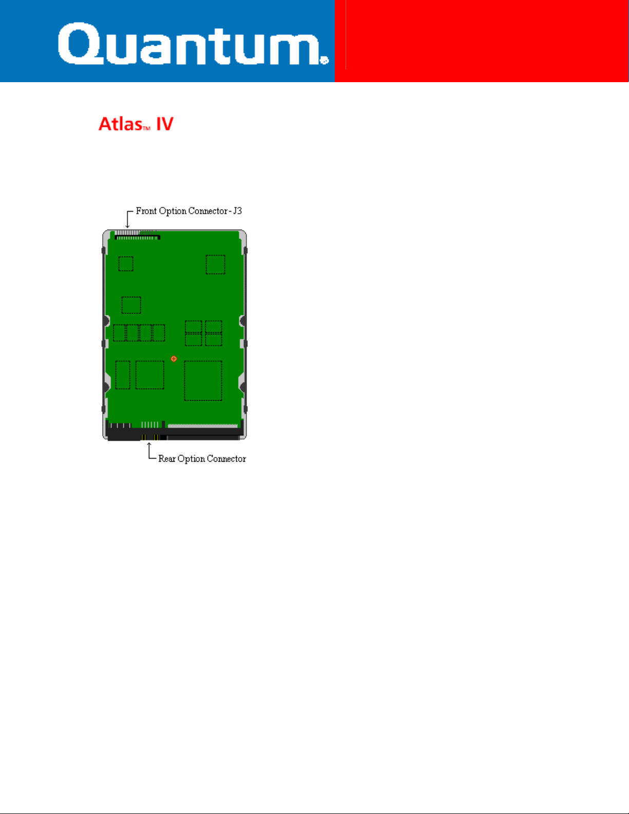
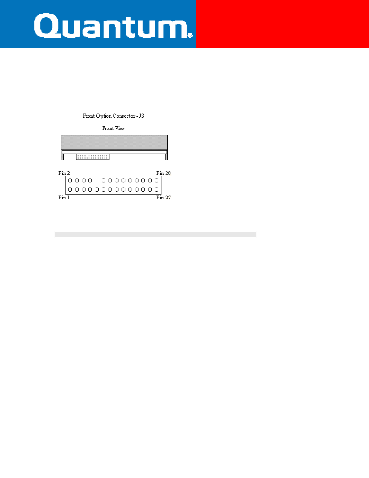
The Atlas IV wide LVD disk drive has two locations where user configurable jumpers are
found. The primary jumper block (Front option connector J3) for the Atlas IV wide LVD
drive is found on the front edge of the disk drive printed circuit board. Using these
jumper pins you can establish the various drive configuration options. The secondary
option jumper block (12-pin) provides an alternate method for setting primary drive
features. The alternate jumper block is located at the rear of the drive and is
incorporated into the SCSI cable connector.
Pin
1
3
5
7
9
11
13
15
17
19
21
23
25
27
Signal
logic_gnd
logic_gnd
logic_gnd
logic_gnd
Fault LED
logic_gnd
logic_gnd
NC
+5V out
logic_gnd
logic_gnd
logic_gnd
logic_gnd
Term Power (TP)
Pin
2
4
6
8
10
12
14
16
18
20
22
24
26
28
Signal
SCSI ID (A3)
SCSI ID (A2)
SCSI ID (A1)
SCSI ID (A0)
Blank (Key, no pin)
Spin Delay (DS)
Force SE (SE)
NC
Busy Out
Write Protect (WP)
Stagger Spin (SS)
No Wide (NW)
Reserved
Term Power (TP)
3 of 3
Page 4

Atlas IV
68-Pin Jumper Settings
Pin
1
3
5
7
9
11
Signal
SCSI ID (A0)
SCSI ID (A1)
SCSI ID (A2)
SCSI ID (A3)
NC
LED Pwr (+5V)
Pin
2
4
6
8
10
12
Signal
XTFault
logic_gnd
logic_gnd
Busy LED
logic_gnd
NC
SCSI ID Settings
The following table identifies the various SCSI ID values and the jumper positions
required to set them.
Drive ID
ID 0
ID 1
ID 2
ID 3
ID 4
ID 5
ID 6
ID 7
ID 8
ID 9
A0
(Pins 7-8)
OFF
ON
OFF
ON
OFF
ON
OFF
ON
OFF
ON
A1
(Pins 5-6)
OFF
OFF
ON
ON
OFF
OFF
ON
ON
OFF
OFF
A2
(Pins 3-4)
OFF
OFF
OFF
OFF
ON
ON
ON
ON
OFF
OFF
A3
(Pins 1-2)
OFF
OFF
OFF
OFF
OFF
OFF
OFF
OFF
ON
ON
4 of 4
Page 5

Atlas IV
68-Pin Jumper Settings
ID 10
ID 11
ID 12
ID 13
ID 14
ID 15
OFF
ON
OFF
ON
OFF
ON
ON
ON
OFF
OFF
ON
ON
OFF
OFF
ON
ON
ON
ON
ON
ON
ON
ON
ON
ON
5 of 5
Page 6

Atlas IV
80-Pin Jumper Settings
80-Pin Jumper Settings
The following describes the jumper options and settings available on the Maxtor®
Atlas™ IV SCA disk drive. For more detail on jumper definitions; please refer to the
jumper definition section.
The Maxtor Atlas IV was developed by Quantum Corporation prior to its merger with
Maxtor.
Fo rce SE (SE)
Enable Single Ended operation
Enable auto switch between Single Ended or LVD operation SE jumper off*
* Indicates default jumper setting
The Atlas IV SCA drive does not provide support for any additional options through the
use of physical jumper settings. Additional feature options are set through the SCA
interface, contact your system manufacturer for details on how to set optional features.
The Atlas IV SCA provides support for:
Stagger Spin, Spin Delay and SCSI ID selection.
SE jumper on
1 of 1
Page 7

Atlas IV
80-Pin Jumper Settings
The Atlas IV SCA does not provide support for:
Active Termination enable, Termination Power and Write Protect.
Jumper Locations
The Atlas IV SCA disk drive has only one location (J7 on PCB) where user configurable
jumpers are found. The jumper block for the Atlas IV SCA drive is found on the disk
drive printed circuit board near the SCA cable connector.
SCSI ID Settings
The Atlas IV SCA drive does not provide for physical configuration of the SCSI ID.
Maxtor, formerly Quantum, disk drives that utilize the 80-pin SCA connector do not
require any jumper configuration for SCSI ID. Systems that use SCA connections,
typically, auto-configure the SCA device. This configuration is determined by the system
at start-up or by user definition during system setup. Contact your system manufacturer
for details on setting SCSI ID.
2 of 2
 Loading...