

Page 1
2X14 SAS Product Manual
512E/4KN models
Standard
ST14000NM0081
* Default configuration is 512E for 512E / 4KN drives.
Section 4.1.2 to Fast Format to 4KN in seconds
See
100868424, Rev. A
August 2020
Page 2
Document Revision History
Revision Date Pages affected and Description of changes
Rev. A 08/31/2020 Initial release.
© 2020 Seagate Technology LLC. All rights reserved.
Publication number: 100868424, Rev. A August 2020
Seagate, Seagate Technology and the Spiral logo are registered trademarks of Seagate Technology LLC in the United States and/or other countries. Raid Rebuild and SeaTools are either
trademarks or registered trademarks of Seagate Technology LLC or one of its affiliated companies in the United States and/or other countries. The FIPS logo is a certification mark of NIST,
which does not imply product endorsement by NIST, the U.S., or Canadian governments. All other trademarks or registered trademarks are the property of their respective owners.
No part of this publication may be reproduced in any form without written permission of Seagate Technology LLC.
Call 877-PUB-TEK1 (877-782-8351) to request permission.
When referring to drive capacity, one gigabyte, or GB, equals one billion bytes and one terabyte, or TB, equals one trillion bytes. Your computer’s operating system may use a different
standard of measurement and report a lower capacity. In addition, some of the listed capacity is used for formatting and other functions, and thus will not be available for data storage.
Actual quantities will vary based on various factors, including file size, file format, features and application software. Actual data rates may vary depending on operating environment
and other factors. The export or re-export of hardware or software containing encryption may be regulated by the U.S. Department of Commerce, Bureau of Industry and Security (for
more information, visit www.bis.doc.gov), and controlled for import and use outside of the U.S. Seagate reserves the right to change, without notice, product offerings or specifications.
Page 3

Contents
Seagate® Technology Support Services . . . . . . . . . . . . . . . . . . . . . . . . . . . . . . . . . . . . . . . . . . . . . . . . . . . . . . . . . . . . . . . 5
1.0 Scope . . . . . . . . . . . . . . . . . . . . . . . . . . . . . . . . . . . . . . . . . . . . . . . . . . . . . . . . . . . . . . . . . . . . . . . . . . . . . . . . . . . . . . . 6
2.0 HDD and SSD Regulatory Compliance and Safety. . . . . . . . . . . . . . . . . . . . . . . . . . . . . . . . . . . . . . . . . . . . . . . 7
2.0.1 Regulatory Models . . . . . . . . . . . . . . . . . . . . . . . . . . . . . . . . . . . . . . . . . . . . . . . . . . . . . . . . . . . . . . . . . 7
2.1 Reference documents . . . . . . . . . . . . . . . . . . . . . . . . . . . . . . . . . . . . . . . . . . . . . . . . . . . . . . . . . . . . . . . . . . . . . . . . 7
3.0 General description . . . . . . . . . . . . . . . . . . . . . . . . . . . . . . . . . . . . . . . . . . . . . . . . . . . . . . . . . . . . . . . . . . . . . . . . . . 8
3.1 Standard features. . . . . . . . . . . . . . . . . . . . . . . . . . . . . . . . . . . . . . . . . . . . . . . . . . . . . . . . . . . . . . . . . . . . . . . . . . . . . 9
3.2 Performance . . . . . . . . . . . . . . . . . . . . . . . . . . . . . . . . . . . . . . . . . . . . . . . . . . . . . . . . . . . . . . . . . . . . . . . . . . . . . . . . . 9
3.3 Reliability . . . . . . . . . . . . . . . . . . . . . . . . . . . . . . . . . . . . . . . . . . . . . . . . . . . . . . . . . . . . . . . . . . . . . . . . . . . . . . . . . . . . 9
3.4 Media description . . . . . . . . . . . . . . . . . . . . . . . . . . . . . . . . . . . . . . . . . . . . . . . . . . . . . . . . . . . . . . . . . . . . . . . . . . . . 9
3.5 Formatted capacities . . . . . . . . . . . . . . . . . . . . . . . . . . . . . . . . . . . . . . . . . . . . . . . . . . . . . . . . . . . . . . . . . . . . . . . . 10
3.6 Factory-installed options. . . . . . . . . . . . . . . . . . . . . . . . . . . . . . . . . . . . . . . . . . . . . . . . . . . . . . . . . . . . . . . . . . . . . 10
4.0 Performance characteristics . . . . . . . . . . . . . . . . . . . . . . . . . . . . . . . . . . . . . . . . . . . . . . . . . . . . . . . . . . . . . . . . . 11
4.1 Internal drive characteristics . . . . . . . . . . . . . . . . . . . . . . . . . . . . . . . . . . . . . . . . . . . . . . . . . . . . . . . . . . . . . . . . . 11
4.1.1 Format command execution time . . . . . . . . . . . . . . . . . . . . . . . . . . . . . . . . . . . . . . . . . . . . . . . . . 11
4.1.2 Fast Format . . . . . . . . . . . . . . . . . . . . . . . . . . . . . . . . . . . . . . . . . . . . . . . . . . . . . . . . . . . . . . . . . . . . . . . 11
4.1.3 General performance characteristics . . . . . . . . . . . . . . . . . . . . . . . . . . . . . . . . . . . . . . . . . . . . . . . 12
4.2 Start/stop time . . . . . . . . . . . . . . . . . . . . . . . . . . . . . . . . . . . . . . . . . . . . . . . . . . . . . . . . . . . . . . . . . . . . . . . . . . . . . . 12
4.3 Prefetch/multi-segmented cache control . . . . . . . . . . . . . . . . . . . . . . . . . . . . . . . . . . . . . . . . . . . . . . . . . . . . . 13
4.4 Cache operation . . . . . . . . . . . . . . . . . . . . . . . . . . . . . . . . . . . . . . . . . . . . . . . . . . . . . . . . . . . . . . . . . . . . . . . . . . . . . 13
4.4.1 Caching write data . . . . . . . . . . . . . . . . . . . . . . . . . . . . . . . . . . . . . . . . . . . . . . . . . . . . . . . . . . . . . . . . 14
4.4.2 Prefetch operation . . . . . . . . . . . . . . . . . . . . . . . . . . . . . . . . . . . . . . . . . . . . . . . . . . . . . . . . . . . . . . . . 14
5.0 Reliability specifications. . . . . . . . . . . . . . . . . . . . . . . . . . . . . . . . . . . . . . . . . . . . . . . . . . . . . . . . . . . . . . . . . . . . . 15
5.1 Error rates . . . . . . . . . . . . . . . . . . . . . . . . . . . . . . . . . . . . . . . . . . . . . . . . . . . . . . . . . . . . . . . . . . . . . . . . . . . . . . . . . . . 15
5.1.1 Recoverable Errors . . . . . . . . . . . . . . . . . . . . . . . . . . . . . . . . . . . . . . . . . . . . . . . . . . . . . . . . . . . . . . . . 15
5.1.2 Unrecoverable Errors . . . . . . . . . . . . . . . . . . . . . . . . . . . . . . . . . . . . . . . . . . . . . . . . . . . . . . . . . . . . . . 15
5.1.3 Seek errors . . . . . . . . . . . . . . . . . . . . . . . . . . . . . . . . . . . . . . . . . . . . . . . . . . . . . . . . . . . . . . . . . . . . . . . . 15
5.1.4 Interface errors . . . . . . . . . . . . . . . . . . . . . . . . . . . . . . . . . . . . . . . . . . . . . . . . . . . . . . . . . . . . . . . . . . . . 15
5.2 Reliability and service . . . . . . . . . . . . . . . . . . . . . . . . . . . . . . . . . . . . . . . . . . . . . . . . . . . . . . . . . . . . . . . . . . . . . . . . 16
5.2.1 Annualized Failure Rate (AFR) and Mean Time Between Failure (MTBF) . . . . . . . . . . . . . . 16
5.2.2 Hot plugging the drive . . . . . . . . . . . . . . . . . . . . . . . . . . . . . . . . . . . . . . . . . . . . . . . . . . . . . . . . . . . . 16
5.2.3 S.M.A.R.T. . . . . . . . . . . . . . . . . . . . . . . . . . . . . . . . . . . . . . . . . . . . . . . . . . . . . . . . . . . . . . . . . . . . . . . . . . 17
5.2.4 Thermal monitor . . . . . . . . . . . . . . . . . . . . . . . . . . . . . . . . . . . . . . . . . . . . . . . . . . . . . . . . . . . . . . . . . . 18
5.2.5 Drive Self Test (DST) . . . . . . . . . . . . . . . . . . . . . . . . . . . . . . . . . . . . . . . . . . . . . . . . . . . . . . . . . . . . . . . 18
5.2.6 Product warranty. . . . . . . . . . . . . . . . . . . . . . . . . . . . . . . . . . . . . . . . . . . . . . . . . . . . . . . . . . . . . . . . . . 20
Seagate Exos 2X14 SAS Product Manual, Rev. A 2
Page 4

Contents
6.0 Physical/electrical specifications . . . . . . . . . . . . . . . . . . . . . . . . . . . . . . . . . . . . . . . . . . . . . . . . . . . . . . . . . . . . . 21
6.1 PowerChoice™ power management. . . . . . . . . . . . . . . . . . . . . . . . . . . . . . . . . . . . . . . . . . . . . . . . . . . . . . . . . . 21
6.1.1 PowerChoice reporting methods . . . . . . . . . . . . . . . . . . . . . . . . . . . . . . . . . . . . . . . . . . . . . . . . . . 22
6.2 Power Balance. . . . . . . . . . . . . . . . . . . . . . . . . . . . . . . . . . . . . . . . . . . . . . . . . . . . . . . . . . . . . . . . . . . . . . . . . . . . . . . 22
6.3 AC power requirements. . . . . . . . . . . . . . . . . . . . . . . . . . . . . . . . . . . . . . . . . . . . . . . . . . . . . . . . . . . . . . . . . . . . . . 22
6.4 DC power requirements . . . . . . . . . . . . . . . . . . . . . . . . . . . . . . . . . . . . . . . . . . . . . . . . . . . . . . . . . . . . . . . . . . . . . 23
6.4.1 Conducted noise immunity . . . . . . . . . . . . . . . . . . . . . . . . . . . . . . . . . . . . . . . . . . . . . . . . . . . . . . . . 24
6.4.2 Power sequencing . . . . . . . . . . . . . . . . . . . . . . . . . . . . . . . . . . . . . . . . . . . . . . . . . . . . . . . . . . . . . . . . 24
6.4.3 Current profiles . . . . . . . . . . . . . . . . . . . . . . . . . . . . . . . . . . . . . . . . . . . . . . . . . . . . . . . . . . . . . . . . . . . 25
6.5 Power dissipation. . . . . . . . . . . . . . . . . . . . . . . . . . . . . . . . . . . . . . . . . . . . . . . . . . . . . . . . . . . . . . . . . . . . . . . . . . . . 26
6.6 Environmental limits. . . . . . . . . . . . . . . . . . . . . . . . . . . . . . . . . . . . . . . . . . . . . . . . . . . . . . . . . . . . . . . . . . . . . . . . . 27
6.6.1 Temperature . . . . . . . . . . . . . . . . . . . . . . . . . . . . . . . . . . . . . . . . . . . . . . . . . . . . . . . . . . . . . . . . . . . . . . 27
6.6.2 Humidity. . . . . . . . . . . . . . . . . . . . . . . . . . . . . . . . . . . . . . . . . . . . . . . . . . . . . . . . . . . . . . . . . . . . . . . . . . 27
6.6.3 Effective altitude (sea level) . . . . . . . . . . . . . . . . . . . . . . . . . . . . . . . . . . . . . . . . . . . . . . . . . . . . . . . . 27
6.6.4 Shock and Vibration . . . . . . . . . . . . . . . . . . . . . . . . . . . . . . . . . . . . . . . . . . . . . . . . . . . . . . . . . . . . . . . 28
6.6.5 Acoustics . . . . . . . . . . . . . . . . . . . . . . . . . . . . . . . . . . . . . . . . . . . . . . . . . . . . . . . . . . . . . . . . . . . . . . . . . 29
6.6.6 Air cleanliness . . . . . . . . . . . . . . . . . . . . . . . . . . . . . . . . . . . . . . . . . . . . . . . . . . . . . . . . . . . . . . . . . . . . . 29
6.6.7 Corrosive environment . . . . . . . . . . . . . . . . . . . . . . . . . . . . . . . . . . . . . . . . . . . . . . . . . . . . . . . . . . . . 29
6.7 Mechanical specifications . . . . . . . . . . . . . . . . . . . . . . . . . . . . . . . . . . . . . . . . . . . . . . . . . . . . . . . . . . . . . . . . . . . . 30
7.0 Defect and error management . . . . . . . . . . . . . . . . . . . . . . . . . . . . . . . . . . . . . . . . . . . . . . . . . . . . . . . . . . . . . . . 31
7.1 Drive internal defects/errors . . . . . . . . . . . . . . . . . . . . . . . . . . . . . . . . . . . . . . . . . . . . . . . . . . . . . . . . . . . . . . . . . 31
7.2 Drive error recovery procedures. . . . . . . . . . . . . . . . . . . . . . . . . . . . . . . . . . . . . . . . . . . . . . . . . . . . . . . . . . . . . . 31
7.3 SAS system errors. . . . . . . . . . . . . . . . . . . . . . . . . . . . . . . . . . . . . . . . . . . . . . . . . . . . . . . . . . . . . . . . . . . . . . . . . . . . 32
7.4 Deferred Auto-Reallocation . . . . . . . . . . . . . . . . . . . . . . . . . . . . . . . . . . . . . . . . . . . . . . . . . . . . . . . . . . . . . . . . . . 32
8.0 Installation . . . . . . . . . . . . . . . . . . . . . . . . . . . . . . . . . . . . . . . . . . . . . . . . . . . . . . . . . . . . . . . . . . . . . . . . . . . . . . . . . 33
8.1 Drive orientation . . . . . . . . . . . . . . . . . . . . . . . . . . . . . . . . . . . . . . . . . . . . . . . . . . . . . . . . . . . . . . . . . . . . . . . . . . . . 33
8.2 Cooling . . . . . . . . . . . . . . . . . . . . . . . . . . . . . . . . . . . . . . . . . . . . . . . . . . . . . . . . . . . . . . . . . . . . . . . . . . . . . . . . . . . . . 34
8.3 Drive mounting . . . . . . . . . . . . . . . . . . . . . . . . . . . . . . . . . . . . . . . . . . . . . . . . . . . . . . . . . . . . . . . . . . . . . . . . . . . . . 35
8.4 Grounding . . . . . . . . . . . . . . . . . . . . . . . . . . . . . . . . . . . . . . . . . . . . . . . . . . . . . . . . . . . . . . . . . . . . . . . . . . . . . . . . . . 35
Seagate Exos 2X14 SAS Product Manual, Rev. A 3
Page 5

Contents
9.0 Interface requirements . . . . . . . . . . . . . . . . . . . . . . . . . . . . . . . . . . . . . . . . . . . . . . . . . . . . . . . . . . . . . . . . . . . . . . 36
9.1 SAS features . . . . . . . . . . . . . . . . . . . . . . . . . . . . . . . . . . . . . . . . . . . . . . . . . . . . . . . . . . . . . . . . . . . . . . . . . . . . . . . . . 36
9.1.1 Task management functions . . . . . . . . . . . . . . . . . . . . . . . . . . . . . . . . . . . . . . . . . . . . . . . . . . . . . . 36
9.1.2 Task management responses . . . . . . . . . . . . . . . . . . . . . . . . . . . . . . . . . . . . . . . . . . . . . . . . . . . . . 36
9.2 SCSI commands supported . . . . . . . . . . . . . . . . . . . . . . . . . . . . . . . . . . . . . . . . . . . . . . . . . . . . . . . . . . . . . . . . . . 37
9.2.1 Inquiry data . . . . . . . . . . . . . . . . . . . . . . . . . . . . . . . . . . . . . . . . . . . . . . . . . . . . . . . . . . . . . . . . . . . . . . . 42
9.2.2 Mode Sense data . . . . . . . . . . . . . . . . . . . . . . . . . . . . . . . . . . . . . . . . . . . . . . . . . . . . . . . . . . . . . . . . . . 43
9.3 Miscellaneous operating features and conditions . . . . . . . . . . . . . . . . . . . . . . . . . . . . . . . . . . . . . . . . . . . . . 45
9.3.1 SAS physical interface . . . . . . . . . . . . . . . . . . . . . . . . . . . . . . . . . . . . . . . . . . . . . . . . . . . . . . . . . . . . . 45
9.3.2 Physical characteristics . . . . . . . . . . . . . . . . . . . . . . . . . . . . . . . . . . . . . . . . . . . . . . . . . . . . . . . . . . . . 48
9.3.3 Connector requirements . . . . . . . . . . . . . . . . . . . . . . . . . . . . . . . . . . . . . . . . . . . . . . . . . . . . . . . . . . 48
9.3.4 Electrical description . . . . . . . . . . . . . . . . . . . . . . . . . . . . . . . . . . . . . . . . . . . . . . . . . . . . . . . . . . . . . . 48
9.3.5 Pin descriptions . . . . . . . . . . . . . . . . . . . . . . . . . . . . . . . . . . . . . . . . . . . . . . . . . . . . . . . . . . . . . . . . . . . 48
9.3.6 SAS transmitters and receivers . . . . . . . . . . . . . . . . . . . . . . . . . . . . . . . . . . . . . . . . . . . . . . . . . . . . . 49
9.3.7 Power. . . . . . . . . . . . . . . . . . . . . . . . . . . . . . . . . . . . . . . . . . . . . . . . . . . . . . . . . . . . . . . . . . . . . . . . . . . . . 49
9.4 Signal characteristics . . . . . . . . . . . . . . . . . . . . . . . . . . . . . . . . . . . . . . . . . . . . . . . . . . . . . . . . . . . . . . . . . . . . . . . . 49
9.4.1 Ready LED Out . . . . . . . . . . . . . . . . . . . . . . . . . . . . . . . . . . . . . . . . . . . . . . . . . . . . . . . . . . . . . . . . . . . . 49
9.4.2 Differential signals . . . . . . . . . . . . . . . . . . . . . . . . . . . . . . . . . . . . . . . . . . . . . . . . . . . . . . . . . . . . . . . . 50
9.5 SAS-3 Specification Compliance . . . . . . . . . . . . . . . . . . . . . . . . . . . . . . . . . . . . . . . . . . . . . . . . . . . . . . . . . . . . . . 50
9.6 Additional information . . . . . . . . . . . . . . . . . . . . . . . . . . . . . . . . . . . . . . . . . . . . . . . . . . . . . . . . . . . . . . . . . . . . . . 50
Seagate Exos 2X14 SAS Product Manual, Rev. A 4
Page 6

Seagate® Technology Support Services
For Seagate Product Support, visit: https://www.seagate.com/support
For Seagate Compliance, Safety, and Disposal, visit: https://www.seagate.com/support
For Firmware Download and Tools Download for Secure Erase, visit: https://www.seagate.com/support/downloads/
For information regarding online support and services, visit: http://www.seagate.com/contacts/
For information regarding Warranty Support, visit: http://www.seagate.com/support/warranty-and-replacements/
For information regarding data recovery services, visit: http://www.seagate.com/services-software/recover/
For Seagate OEM and Distribution partner and Seagate reseller portal, visit: http://www.seagate.com/partners
Seagate Exos 2X14 SAS Product Manual, Rev. A 5
Page 7
www.seagate.com Scope
1.0 Scope
This manual describes Seagate® Exos® 2X14 SAS (Serial Attached SCSI) disk drives.
Exos 2X14 drives support the SAS Protocol specifications to the extent described in this manual. The SAS Interface Manual (part number
100293071) describes the general SAS characteristics of this and other Seagate SAS drives.
Product data communicated in this manual is specific only to the model numbers listed in this manual. The data listed in this manual may not be
predictive of future generation specifications or requirements. If designing a system which will use one of the models listed or future generation
products and need further assistance, please contact the Field Applications Engineer (FAE) or our global support services group as shown in See
“Seagate® Technology Support Services” on page 5 .
Unless otherwise stated, the information in this manual applies to standard and Self-Encrypting Drive models.
Standard 4Kn model
ST14000NM0081
Seagate Exos 2X14 SAS Product Manual, Rev. A 6
Page 8

www.seagate.com HDD and SSD Regulatory Compliance and Safety
2.0 HDD and SSD Regulatory Compliance and Safety
For the latest regulatory and compliance information see: https://www.seagate.com/support/
scroll to bottom of page and click the Compliance, Safety and Disposal Guide link.
2.0.1 Regulatory Models
The following regulatory model number represents all features and configurations within the series:
Regulatory Model Numbers: STL013
2.1 Reference documents
SAS Interface Manual
SCSI Commands Reference Manual
ANSI SAS Documents
ANSI Small Computer System Interface (SCSI) Documents
Specification for Acoustic Test Requirement and Procedures
In case of conflict between this document and any referenced document, this document takes precedence.
Seagate part number: 100293071
Seagate part number: 100293068
SFF-8323 3.5” Drive Form Factor with Serial Connector
SFF-8460 HSS Backplane Design Guidelines
SFF-8470 Multi Lane Copper Connector
SFF-8482 SAS Plug Connector
INCITS 538 SCSI Protocol Layer-4 (SPL-4) Rev. 08
INCITS 534 Serial Attached SCSI (SAS-4)
INCITS 506 SCSI Block Commands-4 (SBC-4) Rev. 10
INCITS 502 SCSI Primary Commands-5 (SPC-5) Rev. 22
INCITS 536 Zoned Block Commands (ZBC) Rev. 5
INCITS 515 SCSI Architecture Model (SAM-5) Rev. 11
Seagate part number: 30553-001
Seagate Exos 2X14 SAS Product Manual, Rev. A 7
Page 9
www.seagate.com General description
3.0 General description
Exos 2X14 enterprise dual-actuator hard drives utilize MACH.2™ technology, enabling up to 2x the performance of an enterprise single-actuator
3.5-inch hard drive. MACH.2TM technology increases performance in a single hard drive by using two independent actuators that can transfer
data to the host computer concurrently. 14TB of capacity is presented to the host system as two independently addressable 7TB logical units,
allowing the user to increase performance while effectively using the full capacity of the drive. Exos 2X14 drives provide high performance, high
capacity data storage for a variety of systems including engineering workstations, network servers, mainframes, and supercomputers. The Serial
Attached SCSI interface is designed to meet next-generation computing demands for performance, scalability, flexibility and high-density storage
requirements.
Exos 2X14 drives are random access storage devices designed to support the Serial Attached SCSI Protocol as described in the ANSI specifications,
this document, and the SAS Interface Manual (part number 100293071) which describes the general interface characteristics of this drive. Exos
2X14 drives are classified as intelligent peripherals and provide level 2 conformance (highest level) with the ANSI SCSI-1 standard. The SAS
connectors, cables and electrical interface are compatible with Serial ATA (SATA), giving future users the choice of populating their systems with
either SAS or SATA hard disk drives. This allows users to continue to leverage existing investment in SCSI while gaining a 12Gb/s serial data transfer
rate.
The head and disk assembly (HDA) is sealed at the factory. Helium recirculates within the HDA through a non-replaceable filter to maintain a
contamination-free HDA environment.
Note
An automatic shipping lock prevents potential damage to the heads and discs that results from movement during shipping and handling. The
shipping lock disengages and the head load process begins when power is applied to the drive.
Exos 2X14 drives decode track 0 location data from the servo data embedded on each surface to eliminate mechanical transducer adjustments
and related reliability concerns.
The drives also use a high-performance actuator assembly with a low-inertia, balanced, patented, straight arm design that provides excellent
performance with minimal power dissipation.
Note
Never disassemble the HDA and do not attempt to service items in the sealed enclosure
(heads, media, actuator, etc.) as this requires special facilities. The drive does not contain userreplaceable parts. Opening the HDA for any reason voids the product warranty.
Seagate recommends validating the configuration with the selected HBA/RAID controller
manufacturer to ensure use of full capacity is supported.
Seagate Exos 2X14 SAS Product Manual, Rev. A 8
Page 10

www.seagate.com General description
3.1 Standard features
Exos 2X14 drives have the following standard features:
• 128 - deep task set (queue)
• 256MB data buffer (see Section 4.4).
• 3.0 / 6.0/12.0 Gb Serial Attached SCSI (SAS) interface
• Drive Self Test (DST)
• Embedded servo design
• Firmware downloadable using the SAS interface
• Flawed logical block reallocation at format time
• Industry standard SFF 3.5-in dimensions
• Jumperless configuration.
• No preventive maintenance or adjustments required
• Perpendicular recording technology
• Power Balance supported (see Section 6.2 on page 22).
•Power Save
• Programmable auto write and read reallocation
• Programmable logical block reallocation scheme
• Reallocation of defects on command (Post Format)
•SAS Power Disable
• Self diagnostics performed when power is applied to the drive
• Support for SAS expanders and fanout adapters
• Supports Single Port operations (Port A)
• Supports up to 32 initiators
• T10 Fast Format supported (see Section 4.1.2)
• Vertical, horizontal, or top down mounting
3.2 Performance
• 1200MB/s maximum instantaneous data transfers.
• 7200 RPM spindle. Average latency = 4.16ms
• Adaptive seek velocity; improved seek performance
• Background processing of queue
• MACH.2 dual actuator technology enables 2X the sequential data rate and up to 1.9X the random performance of a single actuator drive
• Programmable multi-segmentable cache buffer
• Supports start and stop commands (spindle stops spinning)
3.3 Reliability
• 5-year warranty
• Annualized Failure Rate (AFR) of 0.35%
• Balanced low mass rotary voice coil actuator
• Incorporates industry-standard Self-Monitoring Analysis and Reporting Technology (S.M.A.R.T.)
• Mean time between failures (MTBF) of 2,500,000 hours
3.4 Media description
The media used on the drive has a glass substrate coated with a thin film magnetic material, overcoated with a proprietary protective layer for
improved durability and environmental protection.
Seagate Exos 2X14 SAS Product Manual, Rev. A 9
Page 11
www.seagate.com General description
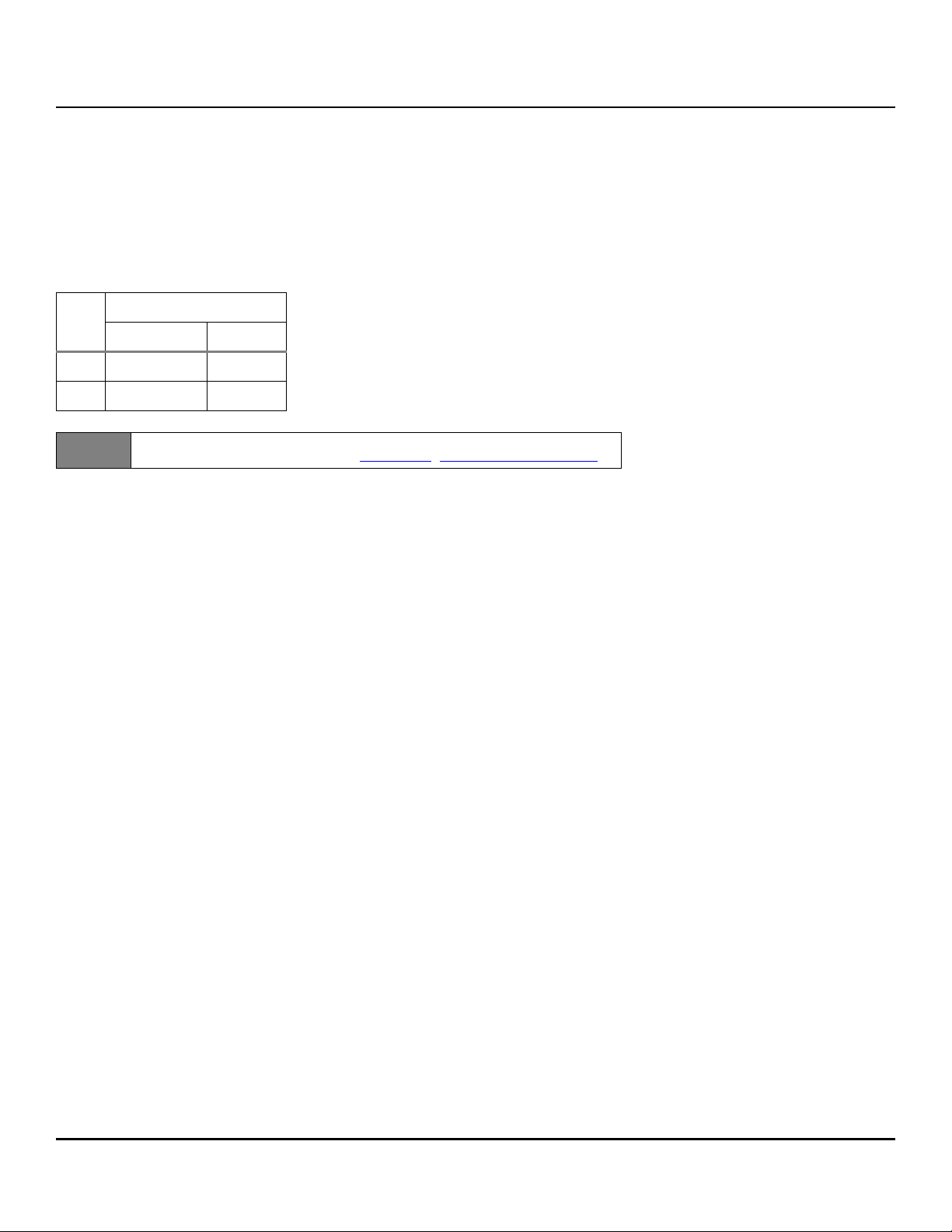
3.5 Formatted capacities
Standard OEM models are formatted to 512 bytes per block for 512 emulation drives and 4096 bytes per block for 4096 native drives. The block
size is selectable at format time. Supported block sizes are 512 emulation drives and 4096 native drives.
To provide a stable target capacity environment and at the same time provide users with flexibility if they choose, Seagate recommends product
planning in one of two modes:
Seagate designs specify capacity points at certain block sizes that Seagate guarantees current and future products will meet. We recommend
customers use this capacity in their project planning, as it ensures a stable operating point with backward and forward compatibility from
generation to generation. The current guaranteed operating points for this product are shown below.
Sector
Size
512 27,344,764,928 65DE00000
4096 3,418,095,616 CBBC0000
Note
14TB w/o PI bytes
Decimal Hex
LBA Counts for drive capacities greater than 8TB are calculated based upon
the SFF-8447 standard publication. ftp://ftp.sea
gate.com/sff/SFF-8447.PDF
3.6 Factory-installed options
Users may order the following items which are incorporated at the manufacturing facility during production or packaged before shipping. Some
of the options available are (not an exhaustive list of possible options):
• Single-unit shipping pack. The drive is normally shipped in bulk packaging to provide maximum protection against transit damage. Units
shipped individually require additional protection as provided by the single unit shipping pack. Users planning single unit distribution should
specify this option.
•The Safety and Regulatory Agency Specifications, part number 75789512, is usually included with each standard OEM drive shipped, but extra
copies may be ordered.
Seagate Exos 2X14 SAS Product Manual, Rev. A 10
Page 12

www.seagate.com Performance characteristics
4.0 Performance characteristics
This section provides detailed information concerning performance-related characteristics and features of Exos 2X14 drives.
4.1 Internal drive characteristics
Drive capacity 14TB (formatted, rounded off value)
Read/write data heads 16
Bytes/track 1,738,365 Bytes (average, rounded off values)
Bytes/surface 875,000 MB (unformatted, rounded off values)
Tracks/surface (total) 479,400 Tracks (user accessible)
Tracks/in 420,000 TPI (average)
Peak bits/in 2,358,000 BPI
Areal density 965 Gb/in
Internal data rate 2765 Mb/s (max)
Disk rotation speed 7200 RPM
Avg rotational latency 4.16 ms
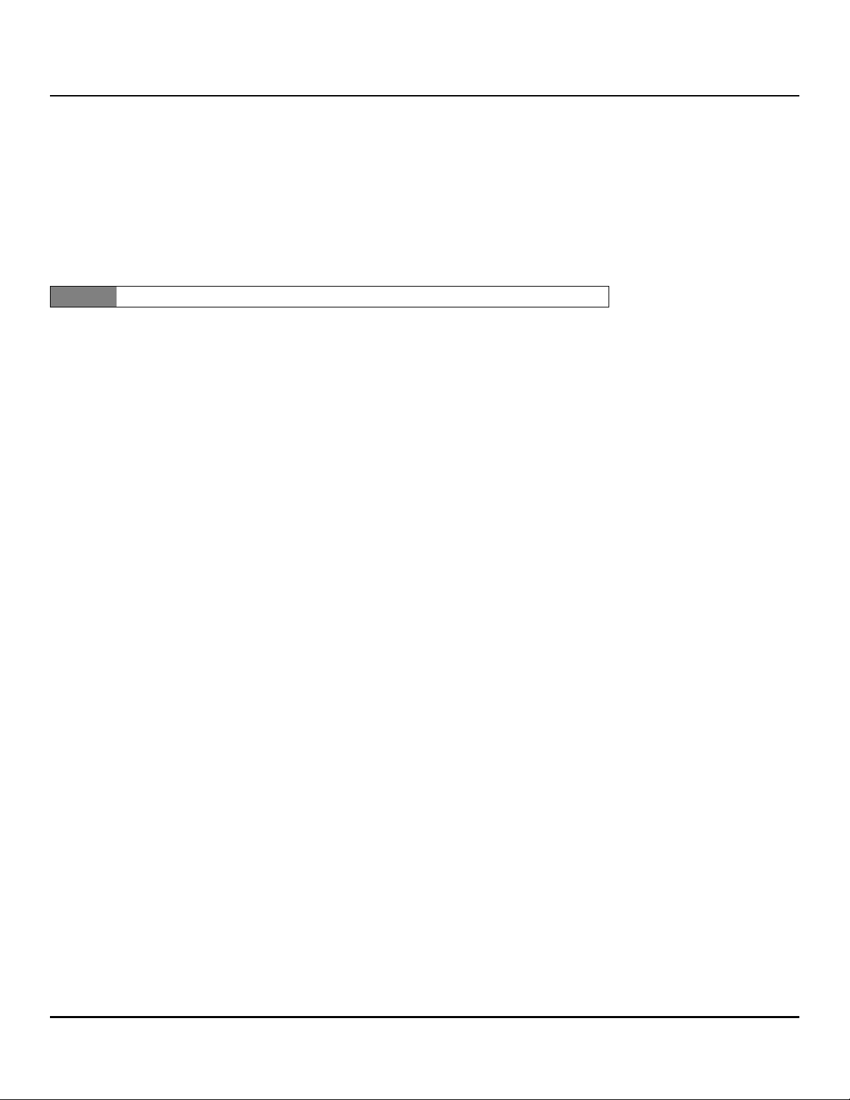
4.1.1 Format command execution time
4Kn-byte sectors (minutes) 512E-byte sectors (minutes)
2
Maximum (with verify)
Maximum (without verify)
Execution time measured from receipt of the last byte of the Command Descriptor Block (CDB) to the request for a Status Byte Transfer to the
Initiator (excluding connect/disconnect).
When changing sector sizes, the format times shown above may need to be increased by 30 minutes.
4.1.2 Fast Format
Drive sector size transition
• Single code to support sector sizes from 512E
• T10 fast format conversion between 512E configurations in the field.
• Possible only if sector sizes are exact multiples of 8 & vice versa
• The selected sector size will take effect only after fast format or full format
• Drive default is 512E from the factory.
• 512E features set after Fast Format
T10 Fast Format
• Implements the fast format based on T10 Spec.
• To request Fast Format, the FFMT bits (Byte 4, Bits 1:0) should be set to 01b.
• A setting of 10b or 11b will return a check condition with 05/24 sense code (pointing to FFMT MSB in CDB).
Mode Select - Parameter list header
• Set Write buffer: // Set Block Descriptor Length = 0x08, Number of LBAs = 0xFFFFFFFF
• 00 00 00 00 00 00 00 08 FF FF FF FF 00 00 02 00 // Set block size to 0512 (0x0200)
• Then Send Mode Select Command
• cdb: 55 01 00 00 00 00 00 00 10 00 // (SP bit = 1, Parameter list = 0x10)
Format Unit - Parameter list header
• Set Write buffer: // Set IMMED = 1
• 00 02 00 00
• Then Send Format Unit Command
• cdb: 04 14 00 00 01 00 // (FMTDAT = 1, DEFECT LIST FORMAT = 010b, FFMT = 01b)
1545 1535
601 599
Seagate Exos 2X14 SAS Product Manual, Rev. A 11
Page 13

www.seagate.com Performance characteristics
4.1.3 General performance characteristics
Minimum sector interleave 1 to 1
Maximum Internal data rate* 2.7 Gb/s
Sustained transfer rate 114 to 250 MiB/s ** (per LUN)
SAS Interface maximum instantaneous transfer rate 1200MB/s* per port
Logical block sizes
512 (default)
4096
Read/write consecutive sectors on a track Yes
Flaw reallocation performance impact (for flaws reallocated at format time using the spare
sectors per sparing zone reallocation scheme.)
Average rotational latency 4.16ms
*Assumes no errors and no relocated logical blocks. Rate measured from the start of the first logical block transfer to or from the host.
** MiB/s x 1.048 = MB/s
Negligible
4.2 Start/stop time
Power-on to ready time is based on typical operating conditions, default full current spin-up profile, and clean shutdown prior to measurement.
To ensure a clean shutdown issue a START STOP UNIT command with the START bit set to zero and the IMMED bit set to zero, so that the device
will return status after the operation is completed.
The drive accepts the commands listed in the SAS Interface Manual less than 3 seconds after DC power has been applied.
If the drive receives a NOTIFY (ENABLE SPINUP) primitive through either port and has not received a START STOP UNIT command with the START
bit equal to 0, the drive becomes ready for normal operations within 30 seconds (excluding the error recovery procedure).
If the drive receives a START STOP UNIT command with the START bit equal to 0 before receiving a NOTIFY (ENABLE SPINUP) primitive, the drive
waits for a START STOP UNIT command with the START bit equal to 1. After receiving a START STOP UNIT command with the START bit equal to 1,
the drive waits for a NOTIFY (ENABLE SPINUP) primitive. After receiving a NOTIFY (ENABLE SPINUP) primitive through either port, the drive
becomes ready for normal operations within 30 seconds (excluding the error recovery procedure).
If the drive receives a START STOP UNIT command with the START bit and IMMED bit equal to 1 and does not receive a NOTIFY (ENABLE SPINUP)
primitive within 5 seconds, the drive fails the START STOP UNIT command.
The START STOP UNIT command may be used to command the drive to stop the spindle. Stop time is 23 seconds (maximum) from removal of DC
power. SCSI stop time is 23 seconds. There is no power control switch on the drive.
An unexpected power loss event, spin up at cold or hot temperature extremes may cause the drive to exceed the typical and max time to ready by
5 to 20 seconds. Extended time to ready is dependent on cache state and environmental conditions prior to the unexpected power loss and
during the subsequent power on.
Seagate Exos 2X14 SAS Product Manual, Rev. A 12
Page 14
www.seagate.com Performance characteristics
4.3 Prefetch/multi-segmented cache control
The drive provides a prefetch (read look-ahead) and multi-segmented cache control algorithms that in many cases can enhance system
performance. Cache refers to the drive buffer storage space when it is used in cache operations. To select this feature, the host sends the Mode
Select command with the proper values in the applicable bytes in page 08h. Prefetch and cache operations are independent features from the
standpoint that each is enabled and disabled independently using the Mode Select command; however, in actual operation, the prefetch feature
overlaps cache operation somewhat as described in sections Table 4.4.1 and Table 4.4.2.
All default cache and prefetch mode parameter values (Mode Page 08h) for standard OEM versions of this drive family are given in Table 7.
4.4 Cache operation
.
Note Refer to the SAS Interface Manual for more detail concerning the cache bits.
The buffer is divided into logical segments from which data is read and to which data is written.
The drive keeps track of the logical block addresses of the data stored in each segment of the buffer. If the cache is enabled (see RCD bit in the SAS
Interface Manual ), data requested by the host with a read command is retrieved from the buffer, if possible, before any disk access is initiated. If
cache operation is not enabled, the buffer is still used, but only as circular buffer segments during disk medium read operations (disregarding
Prefetch operation for the moment). That is, the drive does not check in the buffer segments for the requested read data, but goes directly to the
medium to retrieve it. The retrieved data merely passes through some buffer segment on the way to the host. All data transfers to the host are in
accordance with buffer-full ratio rules. See the explanation provided with the information about Mode Page 02h (disconnect/reconnect control)
in the SAS Interface Manual.
The following is a simplified description of the prefetch/cache operation:
Case A—read command is received and all of the requested logical blocks are already in the cache:
1. Drive transfers the requested logical blocks to the initiator.
Case B—A Read command requests data, and at least one requested logical block is not in any segment of the cache:
1. The drive fetches the requested logical blocks from the disk and transfers them into a segment, and then from there to the host in accor-
dance with the Mode Select Disconnect/Reconnect parameters, page 02h.
2. If the prefetch feature is enabled, refer to section Table 4.4.2 for operation from this point.
Each cache segment is actually a self-contained circular buffer whose length is an integer number of logical blocks. The drive dynamically creates
and removes segments based on the workload. The wrap-around capability of the individual segments greatly enhances the cache’s overall
performance.
The size of each segment is not reported by Mode Sense command page 08h, bytes 14 and 15. The value 0XFFFF is always reported regardless of
the actual size of the segment. Sending a size specification using the Mode Select command (bytes 14 and 15) does not set up a new segment
size. If the STRICT bit in Mode page 00h (byte 2, bit 1) is set to one, the drive responds as it does for any attempt to change an unchangeable
parameter.
Seagate Exos 2X14 SAS Product Manual, Rev. A 13
Page 15

www.seagate.com Performance characteristics
4.4.1 Caching write data
Write caching is a write operation by the drive that makes use of a drive buffer storage area where the data to be written to the medium is stored
while the drive performs the Write command.
If read caching is enabled (RCD=0), then data written to the medium is retained in the cache to be made available for future read cache hits. The
same buffer space and segmentation is used as set up for read functions. The buffer segmentation scheme is set up or changed independently,
having nothing to do with the state of RCD. When a write command is issued, if RCD=0, the cache is first checked to see if any logical blocks that
are to be written are already stored in the cache from a previous read or write command. If there are, the respective cache segments are cleared.
The new data is cached for subsequent Read commands.
If the number of write data logical blocks exceed the size of the segment being written into, when the end of the segment is reached, the data is
written into the beginning of the same cache segment, overwriting the data that was written there at the beginning of the operation; however,
the drive does not overwrite data that has not yet been written to the medium.
If write caching is enabled (WCE=1), then the drive may return Good status on a write command after the data has been transferred into the
cache, but before the data has been written to the medium. If an error occurs while writing the data to the medium, and Good status has already
been returned, a deferred error will be generated.
The Synchronize Cache command may be used to force the drive to write all cached write data to the medium. Upon completion of a Synchronize
Cache command, all data received from previous write commands will have been written to the medium. Table 7 shows the mode default
settings for the drive.
4.4.2 Prefetch operation
If the Prefetch feature is enabled, data in contiguous logical blocks on the disk immediately beyond that which was requested by a Read
command are retrieved and stored in the buffer for immediate transfer from the buffer to the host on subsequent Read commands that request
those logical blocks (this is true even if cache operation is disabled). Though the prefetch operation uses the buffer as a cache, finding the
requested data in the buffer is a prefetch hit, not a cache operation hit.
To enable Prefetch, use Mode Select page 08h, byte 12, bit 5 (Disable Read Ahead - DRA bit). DRA bit = 0 enables prefetch.
The drive does not use the Max Prefetch field (bytes 8 and 9) or the Prefetch Ceiling field (bytes 10 and 11).
When prefetch (read look-ahead) is enabled (enabled by DRA = 0), the drive enables prefetch of contiguous blocks from the disk when it senses
that a prefetch hit will likely occur. The drive disables prefetch when it decides that a prefetch hit is not likely to occur.
Seagate Exos 2X14 SAS Product Manual, Rev. A 14
Page 16

www.seagate.com Reliability specifications
5.0 Reliability specifications
The following reliability specifications assume correct host and drive operational interface, including all interface timings, power supply voltages,
environmental requirements and drive mounting constraints.
8
Seek error rate: Less than 10 errors in 10
Read Error Rates
1
Recovered Data Less than 10 errors in 1012 bits transferred (OEM default settings)
Unrecovered Data Less than 1 sector in 10
Miscorrected Data Less than 1 sector in 10
Interface error rate: Less than 1 error in 1012 bits transferred
Mean Time Between Failure (MTBF): 2,500,000 hours
Annualized Failure Rate (AFR): 0.35%
Preventive maintenance: None required
1. Error rate specified with automatic retries and data correction with ECC enabled and all flaws reallocated.
5.1 Error rates
The error rates stated in this manual assume the following:
• The drive is operated in accordance with this manual using DC power as defined in Section 6.4, DC power requirements
• Errors caused by host system failures are excluded from error rate computations.
• Assume random data.
• Default OEM error recovery settings are applied. This includes AWRE, ARRE, full read retries, full write retries and full retry time.
seeks
15
bits transferred
21
bits transferred
5.1.1 Recoverable Errors
Recoverable errors are those detected and corrected by the drive, and do not require user intervention.
Recoverable Data errors will use correction, although ECC on-the-fly is not considered for purposes of recovered error specifications.
Recovered Data error rate is determined using read bits transferred for recoverable errors occurring during a read, and using write bits transferred
for recoverable errors occurring during a write.
5.1.2 Unrecoverable Errors
An unrecoverable data error is defined as a failure of the drive to recover data from the media. These errors occur due to head/media or write
problems. Unrecoverable data errors are only detected during read operations, but not caused by the read. If an unrecoverable data error is
detected, a MEDIUM ERROR (03h) in the Sense Key will be reported. Multiple unrecoverable data errors resulting from the same cause are treated
as 1 error.
5.1.3 Seek errors
A seek error is defined as a failure of the drive to position the heads to the addressed track. After detecting an initial seek error, the drive
automatically performs an error recovery process. If the error recovery process fails, a seek positioning error (Error code = 15h or 02h) will be
reported with a Hardware error (04h) in the Sense Key. Recoverable seek errors are specified at Less than 10 errors in 10
8
seeks. Unrecoverable
seek errors (Sense Key = 04h) are classified as drive failures.
5.1.4 Interface errors
An interface error is defined as a failure of the receiver on a port to recover the data as transmitted by the device port connected to the receiver.
The error may be detected as a running disparity error, illegal code, loss of word sync, or CRC error.
Seagate Exos 2X14 SAS Product Manual, Rev. A 15
Page 17

www.seagate.com Reliability specifications
5.2 Reliability and service
Users can enhance the reliability of Exos 2X14 disk drives by ensuring that the drive receives adequate cooling. Section 6.0 provides temperature
measurements and other information that may be used to enhance the service life of the drive. Section Table 8.2 provides recommended air-flow
information.
5.2.1 Annualized Failure Rate (AFR) and Mean Time Between Failure (MTBF)
The production disk drive shall achieve an annualized failure-rate of 0.35% (MTBF of 2,500,000 hours) over a 5 year service life when used in
Enterprise Storage field conditions as limited by the following:
• 8760 power-on hours per year.
• HDA temperature as reported by the drive <= 30°C
• Ambient wet bulb temp <= 26°C
•Typical workload
• The AFR (MTBF) is a population statistic not relevant to individual units
• ANSI/ISA S71.04-2013 G2 classification levels and dust contamination to ISO 14644-1 Class 8 standards (as measured at the device)
The MTBF specification for the drive assumes the operating environment is designed to maintain nominal drive temperature and humidity.
Occasional excursions in operating conditions between the rated MTBF conditions and the maximum drive operating conditions may occur
without significant impact to the rated MTBF. However continual or sustained operation beyond the rated MTBF conditions will degrade the drive
MTBF and reduce product reliability.
15
Nonrecoverable read errors 1 per 10
bits read, max
Load unload cycles
(command controlled)
Maximum Rated Workload Maximum rate of <500TB/year/LUN
Warranty
Preventive maintenance None required.
600,000 cycles
Workloads exceeding the annualized rate may degrade the drive MTBF and impact product
reliability. The Annualized Workload Rate is in units of TB per year, or TB per 8760 power on
hours. Workload Rate = TB transferred * (8760 / recorded power on hours).
To determine the warranty for a specific drive, use a web browser to access the following web
page: http://www.sea
From this page, click on the “Is my Drive under Warranty” link. The following are required to be
provided: the drive serial number, model number (or part number) and country of purchase.
The system will display the warranty information for the drive.
gate.com/support/warranty-and-replacements/.
5.2.2 Hot plugging the drive
When a disk is powered on by switching the power or hot plugged, the drive runs a self test before attempting to communicate on its’ interfaces.
When the self test completes successfully, the drive initiates a Link Reset starting with OOB. An attached device should respond to the link reset. If
the link reset attempt fails, or any time the drive looses sync, the drive initiated link reset. The drive will initiate link reset once per second.
If the self-test fails, the drive does not respond to link reset on the failing port.
It is the responsibility of the systems integrator to assure that no temperature, energy, voltage hazard, or ESD potential hazard is presented during
the hot connect/disconnect operation. Discharge the static electricity from the drive carrier prior to inserting it into the system.
Caution
The drive motor must come to a complete stop prior to changing the
plane of operation. This time is required to insure data integrity.
Seagate Exos 2X14 SAS Product Manual, Rev. A 16
Page 18

www.seagate.com Reliability specifications
5.2.3 S.M.A.R.T.
S.M.A.R.T. is an acronym for Self-Monitoring Analysis and Reporting Technology. This technology is intended to recognize conditions that indicate
imminent drive failure and is designed to provide sufficient warning of a failure to allow users to back up the data before an actual failure occurs.
Note
Each monitored attribute has been selected to monitor a specific set of failure conditions in the operating performance of the drive and the
thresholds are optimized to minimize “false” and “failed” predictions.
The drive’s firmware monitors specific attributes for degradation
over time but can’t predict instantaneous drive failures.
Controlling S.M.A.R.T.
The operating mode of S.M.A.R.T. is controlled by the DEXCPT and PERF bits on the Informational Exceptions Control mode page (1Ch). Use the
DEXCPT bit to enable or disable the S.M.A.R.T. feature. Setting the DEXCPT bit disables all S.M.A.R.T. functions. When enabled, S.M.A.R.T. collects
on-line data as the drive performs normal read and write operations. When the PERF bit is set, the drive is considered to be in “On-line Mode Only”
and will not perform off-line functions.
Users can measure off-line attributes and force the drive to save the data by using the Rezero Unit command. Forcing S.M.A.R.T. resets the timer so
that the next scheduled interrupt is in one hour.
Users can interrogate the drive through the host to determine the time remaining before the next scheduled measurement and data logging
process occurs. To accomplish this, issue a Log Sense command to log page 0x3E. This allows the user to control when S.M.A.R.T. interruptions
occur. Forcing S.M.A.R.T. with the RTZ command resets the timer.
Performance impact
S.M.A.R.T. attribute data is saved to the disk so that the events that caused a predictive failure can be recreated. The drive measures and saves
parameters once every one hour subject to an idle period on the drive interfaces. The process of measuring off-line attribute data and saving data
to the disk is interruptible. The maximum on-line only processing delay is summarized below:
Maximum processing delay
Fully-enabled delay DEXCPT = 0
S.M.A.R.T. delay times 75 ms
Reporting control
Reporting is controlled by the MRIE bits in the Informational Exceptions Control mode page (1Ch). An example, if the MRIE is set to one, the
firmware will issue to the host an 01-5D00 sense code. The FRU field contains the type of predictive failure that occurred. The error code is
preserved through bus resets and power cycles.
Determining rate
S.M.A.R.T. monitors the rate at which errors occur and signals a predictive failure if the rate of degraded errors increases to an unacceptable level.
To determine rate, error events are logged and compared to the number of total operations for a given attribute. The interval defines the number
of operations over which to measure the rate. The counter that keeps track of the current number of operations is referred to as the Interval
Counter.
S.M.A.R.T. measures error rates. All errors for each monitored attribute are recorded. A counter keeps track of the number of errors for the current
interval. This counter is referred to as the Failure Counter.
Error rate is the number of errors per operation. The algorithm that S.M.A.R.T. uses to record rates of error is to set thresholds for the number of
errors and their interval. If the number of errors exceeds the threshold before the interval expires, the error rate is considered to be unacceptable.
If the number of errors does not exceed the threshold before the interval expires, the error rate is considered to be acceptable. In either case, the
interval and failure counters are reset and the process starts over.
Seagate Exos 2X14 SAS Product Manual, Rev. A 17
Page 19

www.seagate.com Reliability specifications
Predictive failures
S.M.A.R.T. signals predictive failures when the drive is performing unacceptably for a period of time. The firmware keeps a running count of the
number of times the error rate for each attribute is unacceptable. To accomplish this, a counter is incremented each time the error rate is
unacceptable and decremented (not to exceed zero) whenever the error rate is acceptable. If the counter continually increments such that it
reaches the predictive threshold, a predictive failure is signaled. This counter is referred to as the Failure History Counter. There is a separate Failure
History Counter for each attribute.
5.2.4 Thermal monitor
Exos 2X14 drives implement a temperature warning system which:
1. Signals the host if the temperature exceeds a value which would threaten the drive.
2. Saves a S.M.A.R.T. data frame on the drive which exceeds the threatening temperature value.
A temperature sensor monitors the drive temperature and issues a warning over the interface when the temperature exceeds a set threshold. The
temperature is measured at power-up and then at ten-minute intervals after power-up.
The thermal monitor system generates a warning code of 01-0B01 when the temperature exceeds the specified limit in compliance with the SCSI
standard.
This feature is controlled by the Enable Warning (EWasc) bit, and the reporting mechanism is controlled by the Method of Reporting Informational
Exceptions field (MRIE) on the Informational Exceptions Control (IEC) mode page (1Ch).
5.2.5 Drive Self Test (DST)
Drive Self Test (DST) is a technology designed to recognize drive fault conditions that qualify the drive as a failed unit. DST validates the
functionality of the drive at a system level.
There are two test coverage options implemented in DST:
1. Extended test
2. Short test
The most thorough option is the extended test that performs various tests on the drive and scans every logical block address (LBA) of the drive.
The short test is time-restricted and limited in length—it does not scan the entire media surface, but does some fundamental tests and scans
portions of the media.
If DST encounters an error during either of these tests, it reports a fault condition. If the drive fails the test, remove it from service and return it to
Seagate for service.
5.2.5.1 DST failure definition
The drive will present a “diagnostic failed” condition through the self-tests results value of the diagnostic log page if a functional failure is
encountered during DST. The channel and servo parameters are not modified to test the drive more stringently, and the number of retries are not
reduced. All retries and recovery processes are enabled during the test. If data is recoverable, no failure condition will be reported regardless of
the number of retries required to recover the data.
The following conditions are considered DST failure conditions:
• Seek error after retries are exhausted
• Track-follow error after retries are exhausted
• Read error after retries are exhausted
• Write error after retries are exhausted
Recovered errors will not be reported as diagnostic failures.
Seagate Exos 2X14 SAS Product Manual, Rev. A 18
Page 20

www.seagate.com Reliability specifications
5.2.5.2 Implementation
This section provides all of the information necessary to implement the DST function on this drive.
5.2.5.2.1 State of the drive prior to testing
The drive must be in a ready state before issuing the Send Diagnostic command. There are multiple reasons why a drive may not be ready, some
of which are valid conditions, and not errors. For example, a drive may be in process of doing a format, or another DST. It is the responsibility of the
host application to determine the “not ready” cause.
While not technically part of DST, a Not Ready condition also qualifies the drive to be returned to Seagate as a failed drive.
A Drive Not Ready condition is reported by the drive under the following conditions:
• Motor will not spin
• Motor will not lock to speed
• Servo will not lock on track
• Drive cannot read configuration tables from the disk
In these conditions, the drive responds to a Test Unit Ready command with an 02/04/00 or 02/04/03 code.
5.2.5.2.2 Invoking DST
To invoke DST, submit the Send Diagnostic command with the appropriate Function Code (001b for the short test or 010b for the extended test)
in bytes 1, bits 5, 6, and 7.
5.2.5.2.3 Short and extended tests
DST has two testing options:
1. short
2. extended
These testing options are described in the following two subsections.
Each test consists of three segments: an electrical test segment, a servo test segment, and a read/verify scan segment.
Short test (Function Code: 001b)
The purpose of the short test is to provide a time-limited test that tests as much of the drive as possible within 120 seconds. The short test does
not scan the entire media surface, but does some fundamental tests and scans portions of the media. A complete read/verify scan is not
performed and only factual failures will report a fault condition. This option provides a quick confidence test of the drive.
Extended test (Function Code: 010b)
The objective of the extended test option is to empirically test critical drive components. For example, the seek tests and on-track operations test
the positioning mechanism. The read operation tests the read head element and the media surface. The write element is tested through read/
write/read operations. The integrity of the media is checked through a read/verify scan of the media. Motor functionality is tested by default as a
part of these tests.
The anticipated length of the Extended test is reported through the Control Mode page.
Seagate Exos 2X14 SAS Product Manual, Rev. A 19
Page 21

www.seagate.com Reliability specifications
5.2.5.2.4 Log page entries
When the drive begins DST, it creates a new entry in the Self-test Results Log page. The new entry is created by inserting a new self-test parameter
block at the beginning of the self-test results log parameter section of the log page. Existing data will be moved to make room for the new
parameter block. The drive reports 20 parameter blocks in the log page. If there are more than 20 parameter blocks, the least recent parameter
block will be deleted. The new parameter block will be initialized as follows:
1. The Function Code field is set to the same value as sent in the DST command
2. The Self-Test Results Value field is set to Fh
3. The drive will store the log page to non-volatile memory
After a self-test is complete or has been aborted, the drive updates the Self-Test Results Value field in its Self-Test Results Log page in non-volatile
memory. The host may use Log Sense to read the results from up to the last 20 self-tests performed by the drive. The self-test results value is a 4bit field that reports the results of the test. If the field is set to zero, the drive passed with no errors detected by the DST. If the field is not set to
zero, the test failed for the reason reported in the field.
The drive will report the failure condition and LBA (if applicable) in the Self-test Results Log parameter. The Sense key, ASC, ASCQ, and FRU are
used to report the failure condition.
5.2.5.2.5 Abort
There are several ways to abort a diagnostic. Users can use a SCSI Bus Reset or a Bus Device Reset message to abort the diagnostic.
Users can abort a DST executing in background mode by using the abort code in the DST Function Code field. This will cause a 01 (self-test
aborted by the application client) code to appear in the self-test results values log. All other abort mechanisms will be reported as a 02 (self-test
routine was interrupted by a reset condition).
5.2.6 Product warranty
See “Seagate® Technology Support Services” on page 5 for warranty contact information.
Shipping
When transporting or shipping a drive, use only a Seagate-approved container. Keep the original box. Seagate approved containers are easily
identified by the Seagate Approved Package label. Shipping a drive in a non-approved container voids the drive warranty.
Seagate repair centers may refuse receipt of components improperly packaged or obviously damaged in transit. Contact the authorized Seagate
distributor to purchase additional boxes. Seagate recommends shipping by an air-ride carrier experienced in handling computer equipment.
Storage
Maximum storage periods are 180 days within original unopened Seagate shipping package or 60 days unpackaged within the defined nonoperating limits (refer to environmental section in this manual). Storage can be extended to 1 year packaged or unpackaged under optimal
environmental conditions (25°C, <40% relative humidity non-condensing, and non-corrosive environment). During any storage period the drive
non-operational temperature, humidity, wet bulb, atmospheric conditions, shock, vibration, magnetic and electrical field specifications should be
followed.
Product repair and return information
Seagate customer service centers are the only facilities authorized to service Seagate drives. Seagate does not sanction any third-party repair
facilities. Any unauthorized repair or tampering with the factory seal voids the warranty.
Seagate Exos 2X14 SAS Product Manual, Rev. A 20
Page 22

www.seagate.com Physical/electrical specifications
6.0 Physical/electrical specifications
This section provides information relating to the physical and electrical characteristics of the drive.
6.1 PowerChoice™ power management
Drives using the load/unload architecture provide programmable power management to tailor systems for performance and greater energy
efficiency.
The table below lists the supported PowerChoice modes. The further down the user goes in the table, the more power savings the user gets. For
example, Idle_B mode results in greater power savings than Idle_A mode. Standby_Z mode results in the greatest power savings.
PowerChoice modes
Mode Description
Idle_A Reduced electronics
Idle_B Heads unloaded. Disks spinning at full RPM
Idle_C Heads unloaded. Disks spinning at reduced RPM
Standby_Y Heads unloaded. Disks spinning at reduced RPM.
Recovery requires the NOTIFY (Enable Spinup) command.
Standby_Z Heads unloaded. Motor stopped (disks not spinning)
Recovery requires the NOTIFY (Enable Spinup) command.
PowerChoice can be invoked using one of these two methods:
• Power Condition mode page method—Enable and initialize the idle condition timers and/or the standby condition timers. The timer values are
based on the values set in the Power Condition mode page.
• START STOP UNIT command method—Use the START STOP UNIT command (OPERATION CODE 1Bh). This allows the host to directly transition
the drive to any supported PowerChoice mode.
If both the Power Condition mode page and START STOP UNIT command methods are used, the START STOP UNIT command request takes
precedence over the Power Condition mode page power control and may disable the idle condition and standby condition timers. The REQUEST
SENSE command reports the current PowerChoice state if active and also the method by which the drive entered the PowerChoice state.
When the drive receives a command, all power condition timers are suspended if they were enabled via the Power Condition mode page. Once all
outstanding commands are processed, the power condition timers are reinitialized to the values defined in the Power Condition mode page
Seagate Exos 2X14 SAS Product Manual, Rev. A 21
Page 23

www.seagate.com Physical/electrical specifications
6.1.1 PowerChoice reporting methods
PowerChoice provides these reporting methods for tracking purposes:
Request Sense command reports
• Current power condition
• Method of entry
.
Note Processing the Request Sense command does not impact the drive’s power save state.
Mode Sense command reports (mode page 0x1A)
• Idle conditions enabled / disabled
• Idle condition timer values (100ms increments) (default, saved, current, changeable)
Power Condition Vital Product Data (VPD) Page (VPD page 0x8A)
• Supported power conditions
• Typical recovery time from power conditions (1ms increments)
Start/Stop Cycle Counter Log Page reports (log page 0x0E)
• Specified and accumulated Start/Stops and Load/Unload cycles
Power Condition Transitions Log Page reports (log page 0x1A, subpage 0x00)
• Accumulated transitions to Active, Idle_A, Idle_B, Idle_C, Standby_Y, Standby_Z
6.2 Power Balance
• Mode page 1Ah, subpage 01h byte 6 bits 0 & 1 define the Active Level
• Active Levels - 00b Default,11b Lowest active power level
6.3 AC power requirements
None.
Seagate Exos 2X14 SAS Product Manual, Rev. A 22
Page 24

www.seagate.com Physical/electrical specifications
6.4 DC power requirements
The voltage and typical current requirements for a single drive are shown below. Values indicated apply at the drive connector.
Table 1 DC power requirements (14TB)
Notes
12.0Gb mode
(Amps) (Amps) (Watts)
Voltage +5V +12V
Regulation [5]
± 5% ± 10%
[2]
[2]
Avg idle current DCX [1][6] 0.66 0.32 7.16
Advanced idle current
Idle A [1] 0.66 0.32 7.16
Idle B [1] 0.58 0.20 5.33
Idle C [1] 0.58 0.13 4.49
Standby [1] 0.51 0.01 2.70
Maximum starting current
(peak DC) DC
(peak AC) AC
Delayed motor start (max) DC
[3]
[3]
[3]
1.29 2.22
1.44 2.54
0.62 0.10
Peak operating current (random read 4K16Q)
Typical DCX [1] [8] 0.87 0.67 12.33
Typical DCX, Power Balance enabled [7] [8] 0.86 0.52 10.48
Maximum DC [1] [9] 0.90 0.67
Maximum (peak) DC [10] 1.43 2.53
Peak operating current (random write 4K16Q)
Typical DCX [1] [8] 0.79 0.40 8.73
Typical DCX, Power Balance enabled [7] [8] 0.79 0.40 8.73
Maximum DC [1] [9] 0.81 0.42
Maximum (peak) DC [10] 1.39 1.63
Peak operating current (sequential read 256K16Q)
Typical DCX [1] [8] 1.27 0.59 13.47
Typical DCX, Power Balance enabled [7] [8] 1.02 0.49 11.01
Maximum DC [1] [9] 1.35 0.64
Maximum (peak) DC [10] 1.48 1.55
Peak operating current (sequential write 256K16Q)
Typical DCX [1] [8] 1.25 0.46 11.82
Typical DCX, Power Balance enabled [7] [8] 1.25 0.46 11.82
Maximum DC [1] [9] 1.34 0.50
Maximum (peak) DC [10] 1.41 1.49
Seagate Exos 2X14 SAS Product Manual, Rev. A 23
Page 25

www.seagate.com Physical/electrical specifications
[1] Measured with an oscilloscope & current probes at 20 megasamples/second (50ns/point). Power supply at nominal voltage.
N (number of drives tested) = 12, 35oC ambient.
[2] For +12 V, a –10% tolerance is allowed during initial spindle start but must return to ± 5% before reaching 7200 RPM.
The ± 5% must be maintained after the drive signifies that its power-up sequence has been completed and
that the drive is able to accept selection by the host initiator.
[3] See +12V current profile in Figure 1. (for 14TB models)
[4] This condition occurs after OOB and Speed Negotiation completes but before the drive has received the Notify Spinup primitive.
[5] See 6.4.1, "Conducted noise immunity." Specified voltage tolerance includes ripple, noise, and transient response.
[6] During idle, the drive heads are relocated every 60 seconds to a random location within the band from three-quarters to maximum track.
[7] Power Balance allows the user to lower drive power at a performance loss (approximately 6% random, 50% sequential).
See Section 6.2, "Power Balance" for details on how to enable Power Balance.
[8] “Typical DCX” is an average current value of all drives tested, i.e. avg(I
avg,drive1
[9] “Maximum DC” is the maximum average operating current of all drives tested, i.e. max(I
, I
avg,drive2
,... I
avg,driveN
avg,drive1
).
, I
avg,drive2
,... I
avg,driveN
).
Note that the maximum DC 5V current value & maximum DC 12V current value are from different drives.
[10] “Maximum (peak) DC” is the maximum single point (>=50ns in duration) recorded by the oscilloscope on any of the drives tested,
i.e. max(I
maxpoint,drive1
, I
maxpoint,drive2
,... I
maxpoint,driveN
).
General DC power requirement notes.
1. Minimum current loading for each supply voltage is not less than 1.7% of the maximum operating current shown.
2. The +5V and +12V supplies should employ separate ground returns.
3. Where power is provided to multiple drives from a common supply, careful consideration for individual drive power requirements should be
noted. Where multiple units are powered on simultaneously, the peak starting current must be available to each device.
4. Parameters, other than spindle start, are measured after a 10-minute warm up.
5. Idle power after power-on will be higher than indicated until the drive has verified the media. Idle power will then return to the indicated
values.
6. Drive hardware limits +5V current draw to approximately 1.4A
avg
.
6.4.1 Conducted noise immunity
Noise is specified as a periodic and random distribution of frequencies covering a band from DC to 10 MHz. Maximum allowed noise values given
below are peak-to-peak measurements and apply at the drive power connector.
+5v = 250 mV pp from 100 Hz to 20 MHz.
+12v = 250 mV pp from 100 Hz to 5 MHz.
6.4.2 Power sequencing
The drive does not require power sequencing. The drive protects against inadvertent writing during power-up and down.
Seagate Exos 2X14 SAS Product Manual, Rev. A 24
Page 26

www.seagate.com Physical/electrical specifications
6.4.3 Current profiles
The +12V (top) and +5V (bottom) current profiles for the Exos 2X14 drives are shown below.
Figure 1. 14TB model current profiles.
Note
All times and currents are typical. See Table 1 for maximum current requirements.
Seagate Exos 2X14 SAS Product Manual, Rev. A 25
Page 27

www.seagate.com Physical/electrical specifications
6.5 Power dissipation
14TB models in 12Gb operation
Please refer to Table 1 for power dissipation numbers.
To obtain operating power for typical random read operations, refer to the following I/O rate curve (see Figure 2.). Locate the typical I/O rate for a
drive in the system on the horizontal axis and read the corresponding +5 volt current, +12 volt current, and total watts on the vertical axis. To
calculate BTUs per hour, multiply watts by 3.4123.
Figure 2. 14TB models (12Gb) DC current and power vs. input/output operations per second
Seagate Exos 2X14 SAS Product Manual, Rev. A 26
Page 28

www.seagate.com Physical/electrical specifications
6.6 Environmental limits
Temperature and humidity values experienced by the drive must be such that condensation does not occur on any drive part. Altitude and
atmospheric pressure specifications are referenced to a standard day at 58.7°F (14.8°C).
To maintain optimal performance drives should be run at nominal drive temperatures and humidity
Note
6.6.1 Temperature
a. Operating
41°F to 140°F (5°C to 60°C) temperature range with a maximum temperature gradient of 36°F (20°C) per hour as reported by the
drive.
The maximum allowable drive reported temperature is 140°F (60°C).
Air flow may be required to achieve consistent nominal drive temperature values (see Section 8.2). To confirm that the required
cooling is provided for the electronics and HDA, place the drive in its final mechanical configuration, and perform random
write/read operations. After the temperatures stabilize, monitor the current drive temperature using the Temperature log page
(0Dh), with PARAMETER CODE 0000H TEMPERATURE. The TEMPERATURE field (byte 9) indicates the temperature of the SCSI
target device in degrees Celsius at the time the LOG SENSE command is performed.
b. Non-operating
–40° to 158°F (–40° to 70°C) package ambient with a maximum gradient of 36°F (20°C) per hour. This specification assumes that
the drive is packaged in the shipping container designed by Seagate for use with drive.
See Section 5.0, "Reliability specifications" for rated MTBF device operating condition requirements.
6.6.2 Humidity
The values below assume that no condensation on the drive occurs. Maximum wet bulb temperature is 84.2°F (29°C).
a. Operating
5% to 95% non-condensing relative humidity with a maximum gradient of 20% per hour.
b. Non-operating
5% to 95% non-condensing relative humidity.
6.6.3 Effective altitude (sea level)
a. Operating
–1000 to +10,000 feet (–304.8 to +3048 meters)
b. Non-operating
–1000 to +40,000 feet (–304.8 to +12,192 meters)
Seagate Exos 2X14 SAS Product Manual, Rev. A 27
Page 29

www.seagate.com Physical/electrical specifications
6.6.4 Shock and Vibration
Shock and vibration measurements specified in this document are made directly on the drive itself and applied in the X, Y, and Z axis at the drive
mounting point locations.
6.6.4.1 Shock
a. Operating
The drive will operate without error while subjected to intermittent shock pulses not exceeding 50g at a duration of 2ms.
b. Non-operating
The drive will operate without non-recoverable errors after being subjected to shock pulses not exceeding 200g at a duration of
2ms.
6.6.4.2 Vibration
a. Linear Random Operating Vibration
The drive will operate without non-recoverable errors while being subjected to the random power spectral density noise
specified below.
b. Random Rotary Operating Vibration
The drive will exhibit greater than 90% throughput for sequential and random write operations while subjected to the shaped
random power spectral density noise specified below.
c. Linear Random Non-Operating Vibration
The drive will not incur physical damage or have non-recoverable errors after being subjected to the power spectral density
noise specified below.
Seagate Exos 2X14 SAS Product Manual, Rev. A 28
Page 30

www.seagate.com Physical/electrical specifications
6.6.5 Acoustics
Sound power during idle mode shall be 2.8 bels typical when measured to ISO 7779 specification.
Sound power while operating shall be 3.0 bels typical when measured to ISO 7779 specification.
There will not be any discrete tones more than 9 dB above the masking noise when measured according to
Seagate specification 30553-001.
6.6.6 Air cleanliness
The drive is designed to operate in a typical office environment with minimal environmental control.
6.6.7 Corrosive environment
Seagate electronic drive components pass accelerated corrosion testing equivalent to 10 years exposure to light industrial environments
containing sulfurous gases, chlorine and nitric oxide, classes G and H per ASTM B845. However, this accelerated testing cannot duplicate every
potential application environment.
Users should use caution exposing any electronic components to uncontrolled chemical pollutants and corrosive chemicals as electronic drive
component reliability can be affected by the installation environment. The silver, copper, nickel and gold films used in hard disk drives are
especially sensitive to the presence of sulfide, chloride, and nitrate contaminants. Sulfur is found to be the most damaging. Materials used in
cabinet fabrication, such as vulcanized rubber, that can outgas corrosive compounds should be minimized or eliminated. The useful life of any
electronic equipment may be extended by replacing materials near circuitry with sulfide-free alternatives.
Seagate recommends that data centers be kept clean by monitoring and controlling the dust and gaseous contamination. Gaseous
contamination should be within ANSI/ISA S71.04-2013 G2 classification levels (as measured on copper and silver coupons), and dust
contamination to ISO 14644-1 Class 8 standards, and MTBF rated conditions as defined in the Annualized Failure Rate (AFR) and Mean Time
Between Failure (MTBF) section.
Seagate Exos 2X14 SAS Product Manual, Rev. A 29
Page 31

www.seagate.com Physical/electrical specifications
OF DRIVE
4.000±.010
2X 1.625±.020
2X 3.000±.010
.123±.010
1.432
2.000
.814 OF CONN
Y
B
4.000±.010
1.122±.020
4X .250±.010
5.787
146.99
MAX
Y
Z
1.028
26.11
MAX
.140±.015
2.000
OF DRIVE
Z
Y
4X 6-32 UNC 2B
3 MIN THREAD DEPTH
MOUNTING HOLE.
MAX TORQUE 6 IN/LBS
.15 MAX FASTENER PENETRATION
0.169 ± 0.16 x 90
6X 6-32 UNC-2B
.150 FASTENER PENETRATION
0.160 ± 0.10 x 90
MAX TORQUE: 6 IN-LBS
3 MIN THREAD DEPTH
6.7 Mechanical specifications
Refer to Figure 3 for detailed mounting configuration dimensions. See Section 8.3, “Drive mounting.”
Weight : 1.510 lb 685 g
Note
These dimensions conform to the Small Form Factor Standard documented in SFF-8301
and SFF-8323, found at www.snia.org/technology-communities/sff/specifications
.
Figure 3. Mounting configuration dimensions
Note The image is for mechanical dimension reference only and may not represent the actual drive.
Seagate Exos 2X14 SAS Product Manual, Rev. A 30
Page 32

www.seagate.com Defect and error management
7.0 Defect and error management
Seagate continues to use innovative technologies to manage defects and errors. These technologies are designed to increase data integrity,
perform drive self-maintenance, and validate proper drive operation.
SCSI defect and error management involves drive internal defect/error management and SAS system error considerations (errors in
communications between the initiator and the drive). In addition, Seagate provides the following technologies used to increase data integrity and
drive reliability:
• Deferred Auto-Reallocation (see Section Figure 7.4)
The read error rates and specified storage capacities are not dependent on host (initiator) defect management routines.
7.1 Drive internal defects/errors
During the initial drive format operation at the factory, media defects are identified, tagged as being unusable, and their locations recorded on
the drive primary defects list (referred to as the “P’ list and also as the ETF defect list). At factory format time, these known defects are also
reallocated, that is, reassigned to a new place on the medium and the location listed in the defects reallocation table. The “P” list is n o t a l tered
after factory formatting. Locations of defects found and reallocated during error recovery procedures after drive shipment are listed in the “G” list
(defects growth list). The “P” and “G” lists may be referenced by the initiator using the Read Defect Data command.
Details of the SCSI commands supported by the drive are described in the SAS Interface Manual. Also, more information on the drive Error
Recovery philosophy is presented in the SAS Interface Manual.
7.2 Drive error recovery procedures
When an error occurs during drive operation, the drive, if programmed to do so, performs error recovery procedures to attempt to recover the
data. The error recovery procedures used depend on the options previously set in the Error Recovery Parameters mode page. Error recovery and
defect management may involve using several SCSI commands described in the SAS Interface Manual. The drive implements selectable error
recovery time limits required in video applications.
The error recovery scheme supported by the drive provides a way to control the total error recovery time for the entire command in addition to
controlling the recovery level for a single LBA. The total amount of time spent in error recovery for a command can be limited using the Recovery
Time Limit bytes in the Error Recovery mode page. The total amount of time spent in error recovery for a single LBA can be limited using the Read
Retry Count or Write Retry Count bytes in the Error Recovery mode page.
The drive firmware error recovery algorithms consist of 12 levels for read recoveries and five levels for write. Each level may consist of multiple
steps, where a step is defined as a recovery function involving a single re-read or re-write attempt. The maximum level used by the drive in LBA
recovery is determined by the read and write retry counts.
Tab le Table 2 equates the read and write retry count with the maximum possible recovery time for read and write recovery of individual LBAs. The
times given do not include time taken to perform reallocations. Reallocations are performed when the ARRE bit (for reads) or AWRE bit (for writes)
is one, the RC bit is zero, and the recovery time limit for the command has not yet been met. Time needed to perform reallocation is not counted
against the recovery time limit.
When the RC bit is one, reallocations are disabled even if the ARRE or AWRE bits are one. The drive will still perform data recovery actions within
the limits defined by the Read Retry Count, Write Retry Count, and Recovery Time Limit parameters. However, the drive does not report any
unrecovered errors.
Seagate Exos 2X14 SAS Product Manual, Rev. A 31
Page 33

www.seagate.com Defect and error management
Table 2 Read and write retry count maximum recovery time
Read retry count*
1 124.32 1 53.91
5 621.62 2 79.89
10 1243.23 3 97.86
15 1864.85 4 175.85
20 (default) 2486.47 5 (default) 421.79
* For read retry count, every tick ~ 5% of total error recovery. Valid range setting is 1-20.
e.g. 1 ~ 5%
5 ~ 25%
20 ~ 100%
Setting these retry counts to a value below the default setting could result in degradation of the unrecovered error rate. For example, suppose the
read/write recovery page has the RC bit = 0 and if the read retry count is set to 5, this means ~ 25% of error recovery will be executed which
consumes 621.62 ms (please refer to the table above). If the limit is reached and a LBA has not yet been recovered (i.e. requires retries beyond
621.62 ms), the command will end with Check Condition status report and unrecoverable read error will be reported.
Maximum recovery time per
LBA (cumulative, ms)
Write retry count*
0 35.94
Maximum recovery time per
LBA (cumulative, ms)
7.3 SAS system errors
Information on the reporting of operational errors or faults across the interface is given in the SAS Interface Manual. The SSP Response returns
information to the host about numerous kinds of errors or faults. The Receive Diagnostic Results reports the results of diagnostic operations
performed by the drive.
Status returned by the drive to the initiator is described in the SAS Interface Manual. Status reporting plays a role in systems error management
and its use in that respect is described in sections where the various commands are discussed.
7.4 Deferred Auto-Reallocation
Deferred Auto-Reallocation (DAR) simplifies reallocation algorithms at the system level by allowing the drive to reallocate unreadable locations on
a subsequent write command. Sites are marked for DAR during read operations performed by the drive. When a write command is received for an
LBA marked for DAR, the auto-reallocation process is invoked and attempts to rewrite the data to the original location. If a verification of this
rewrite fails, the sector is re-mapped to a spare location.
This is in contrast to the system having to use the Reassign Command to reassign a location that was unreadable and then generate a write
command to rewrite the data. DAR is most effective when AWRE and ARRE are enabled—this is the default setting from the Seagate factory. With
AWRE and ARRE disabled DAR is unable to reallocate the failing location and will report an error sense code indicating that a write command is
being attempted to a previously failing location.
Seagate Exos 2X14 SAS Product Manual, Rev. A 32
Page 34

www.seagate.com Installation
8.0 Installation
Exos 2X14 disk drive installation is a plug-and-play process. There are no jumpers, switches, or terminators on the drive.
SAS drives are designed to be used in a host system that provides a SAS-compatible backplane with bays designed to accommodate the drive. In
such systems, the host system typically provides a carrier or tray into which users need to mount the drive. Mount the drive to the carrier or tray
provided by the host system only using 6-32 UNC mounting screws. The screws should be inserted no more than 0.140 in (3.56mm) into the
bottom or side mounting holes. When tightening the screws, do not overtighten use a maximum torque of 6 in-lb. Users can mount the drive in
any orientation.
SAS drives are designed to be attached to the host system without I/O or power cables. If users intend the
Note
Slide the carrier or tray into the appropriate bay in the host system using the instructions provided by the host system. This connects the drive
directly to the system’s SAS connector. The SAS connector is normally located on a SAS backpanel. See Section 9.3.1 for additional information
about these connectors.
Power is supplied through the SAS connector.
The drive is shipped from the factory low-level formatted in 512-byte logical blocks. Users need to reformat the drive only if selecting a different
logical block size.
use the drive in a non-backplane host system, connecting the drive using high-quality cables is acceptable
as long as the I/O cable length does not exceed 4 meters (13.1 feet).
Figure 4. Physical interface
Note Image is for reference only, may not represent actual drive.
8.1 Drive orientation
The drive may be mounted in any orientation. All drive performance characterizations, however, have been done with the drive in horizontal
(discs level) and vertical (drive on its side) orientations, which are the two preferred mounting orientations.
Seagate Exos 2X14 SAS Product Manual, Rev. A 33
Page 35

www.seagate.com Installation
Above unit
Under unit
Note. Air flows in the direction shown (back to front)
or in reverse direction (front to back)
Above unit
Under unit
Note. Air flows in the direction shown or
in reverse direction (side to side)
8.2 Cooling
Cabinet cooling must be designed by the customer so that the ambient temperature immediately surrounding the drive will not exceed
temperature conditions specified in Section 6.6.1, "Temperature"
The rack, cabinet, or drawer environment for the drive must provide heat removal from the electronics and head and disk assembly (HDA). Users
should confirm that adequate heat removal is provided using the temperature measurement guidelines described in Section 6.6.1.
Forced air flow may be required to keep temperatures at or below the temperatures specified in Section Table 6.6.1 in which case the drive
should be oriented, or air flow directed, so that the least amount of air flow resistance is created while providing air flow to the electronics and
HDA. Also, the shortest possible path between the air inlet and exit should be chosen to minimize the travel length of air heated by the drive and
other heat sources within the rack, cabinet, or drawer environment.
If forced air is determined to be necessary, possible air-flow patterns are shown in Figure 5. The air-flow patterns are created by one or more fans,
either forcing or drawing air as shown in the illustrations. Conduction, convection, or other forced air-flow patterns are acceptable as long as the
temperature measurement guidelines of Section 6.6.1 are met.
Figure 5. Air flow
Note Image is for reference only, may not represent actual drive.
Seagate Exos 2X14 SAS Product Manual, Rev. A 34
Page 36

www.seagate.com Installation
K x X = F < 15lb = 67N
8.3 Drive mounting
Mount the drive using the bottom or side mounting holes. If mounting the drive using the bottom holes, ensure the drive is not physically
distorted by attempting to mount it on a stiff, non-flat surface.
The allowable mounting surface stiffness is 80 lb/in (14.0 N/mm). The following equation and paragraph define the allowable mounting surface
stiffness:
where K is the mounting surface stiffness (units in lb/in or N/mm) and X is the out-of-plane surface distortion (units in inches or millimeters). The
out-of-plane distortion (X) is determined by defining a plane with three of the four mounting points fixed and evaluating the out-of-plane
deflection of the fourth mounting point when a known force (F) is applied to the fourth point.
8.4 Grounding
Signal ground (PCBA) and HDA ground are connected together in the drive and cannot be separated by the user. The equipment in which the
drive is mounted is connected directly to the HDA and PCBA with no electrically isolating shock mounts. If it is desired for the system chassis to
not be connected to the HDA/PCBA ground, the systems integrator or user must provide a nonconductive (electrically isolating) method of
mounting the drive in the host equipment.
Increased radiated emissions may result if users do not provide the maximum surface area ground connection between system ground and drive
ground. This is the system designer’s and integrator’s responsibility.
Seagate Exos 2X14 SAS Product Manual, Rev. A 35
Page 37

www.seagate.com Interface requirements
9.0 Interface requirements
This section partially describes the interface requirements as implemented on the Single Port Exos 2X14 drives. Additional information is provided
in the SAS Interface Manual (part number 100293071).
9.1 SAS features
This section lists the SAS-specific features supported by Exos 2X14 drives.
9.1.1 Task management functions
Tab le Table 3 lists the SAS task management functions supported.
Table 3 SAS task management functions supported
Task name Supported
Abort Task Yes
Clear ACA Yes
Clear task set Yes
Abort task set Yes
Logical Unit Reset Yes
Query Task Yes
9.1.2 Task management responses
Tab le Table 4 lists the SAS response codes returned for task management functions supported.
Table 4 Task management response codes
Function name Response code
Function complete 00
Invalid frame 02
Function not supported 04
Function failed 05
Function succeeded 08
Invalid logical unit 09
Seagate Exos 2X14 SAS Product Manual, Rev. A 36
Page 38

www.seagate.com Interface requirements
9.2 SCSI commands supported
Tab le Table 5 lists the SCSI commands supported by Exos 2X14 drives.
Table 5 Supported commands
Command name Command code
Change Definition 40h N
Close Zone (16) 94h/01h N
Compare 39h N
Copy 18h N
Copy and Verify 3Ah N
Finish Zone (16) 94h/02h N
Format Unit
DCRT bit supported Y
DPRY bit supported N
DSP bit supported Y
IMMED bit supported Y
IP bit supported Y
SI (Security Initialize) bit supported N
STPF bit supported Y
VS (vendor specific) N
Get Physical Element Status 9Eh/17h 00 Y
Inquiry 12h 00 Y
Block Device Characteristics (B1h) Y
Block Limits (B0h) Y
Date Code page (C1h) Y
Device Behavior page (C3h) Y
Device Identification (83h) Y
Extended Inquiry Data (86h) Y
Firmware Numbers page (C0h) Y
Implemented Operating Def page (81h) N
Jumper Settings page (C2h) Y
Logical Block Provisioning (B2h) Y
Mode Page Policy (87h) Y
Power Condition (8Ah) Y
Protocol Specific Logical Unit Information (90h) Y
Protocol Specific Port Information (91h) Y
SCSI Ports (88h) Y
Supported Vital Product Data page (00h) Y
Unit Serial Number page (80h) Y
Lock-unlock cache 36h N
Log Select 4Ch 00 Y
PCR bit Y
DU bit N
[4]
04h 00 Y
MLU
[5]
Supported
[3]
Seagate Exos 2X14 SAS Product Manual, Rev. A 37
Page 39

www.seagate.com Interface requirements
Table 5 Supported commands
Command name Command code
MLU
[5]
DS bit Y
TSD bit Y
ETC bit N
TMC bit N
LP bit N
Log Sense 4Dh 00 Y
Application Client Log page (0Fh) Y
Background Scan Results page (15h) (SBC-3) Y
Buffer Over-run/Under-run page (01h) N
Cache Statistics page (37h) Y
Factory Log page (3Eh) Y
Format Status page (08h) Y
Information Exceptions Log page (2Fh) Y
Last n Deferred Errors or Asynchronous Events page (0Bh) N
Last n Error Events page (07h) N
Non-medium Error page (06h) Y
Pages Supported list (00h) Y
Power Condition Transition page (1Ah) Y
Protocol Specific Port page (18h) Y
Read Error Counter page (03h) Y
Read Reverse Error Counter page (04h) N
Self-test Results page (10h) Y
Start-stop Cycle Counter page (0Eh) Y
Temperature page (0Dh) Y
Verify Error Counter page (05h) Y
Write error counter page (02h) Y
Mode Select (same pages as Mode Sense 1Ah) 15h 00 Y
Mode Select (10) (same pages as Mode Sense 1Ah) 55h 00 Y
Mode Sense 1Ah 00 Y
Caching Parameters page (08h) Y
Control Mode page (0Ah) Y
Disconnect/Reconnect (02h) Y
Error Recovery page (01h) Y
Format page (03h) Y
Information Exceptions Control page (1Ch/01h) Y
Background Scan mode subpage (01h) Y
Notch and Partition Page (0Ch) N
Protocol-Specific Port page (19h) Y
Power Condition page (1Ah) Y
Rigid disk Drive Geometry page (04h) Y
Unit Attention page (00h) Y
Supported
[1]
[1]
[3]
Seagate Exos 2X14 SAS Product Manual, Rev. A 38
Page 40

www.seagate.com Interface requirements
Table 5 Supported commands
Command name Command code
Verify Error Recovery page (07h) Y
Xor Control page (10h) N
Mode Sense (10) (same pages as Mode Sense 1Ah) 5Ah 00 Y
Open Zone (16) 94h/03h N
Persistent Reserve In 5Eh N
Persistent Reserve Out 5Fh N
Prefetch (10) 34h N
Prefetch (16) 90h N.A.
Read (6) 08h 01 Y
Read (10) 28h 01 Y
DPO bit supported Y
FUA bit supported Y
Read (12) A8h N
Read (16) 88h 01 Y
Read (32) 7Fh/0009h 01 Y
Read Buffer (10) (modes 0h, 2h, 3h, Ah, Bh and 1ch supported) 3Ch 00 Y (non-SED drives only)
Read Buffer (16) (modes 0h, 2h, 3h, Ah, Bh and 1ch supported) 9Bh 00 Y (non-SED drives only)
Read Capacity (10) 25h 00 Y
Read Capacity (16) 9Eh/10h 00 Y
Read Defect Data (10) 37h 00 Y
Read Defect Data (12) B7h 00 Y
Read Long (10) 3Eh N
Read Long (16) 9Eh/11h N
Reassign Blocks 07h 00 Y
Receive Diagnostic Results 1Ch 00 Y
Supported Diagnostics pages (00h) Y
Translate page (40h) Y
Release (6) 17h N
Release (10) 57h 00 Y
Remove Element And Truncate 9Eh/18h 00 Y
Report Identifying Information A3h/05h 00 Y
Report LUNs A0h 00 Y
Report Supported Operation Codes A3h/0Ch 00 Y
Report Supported Task Management Functions A3h/0Dh 00 Y
Report Timestamp A3h/0Fh 00 Y
Report Zones 95h/00h N
Request Sense 03h 00 Y
Actual Retry Count bytes Y
Extended Sense Y
Field Pointer bytes Y
Reserve (6) 16h 00 Y
MLU
[5]
Supported
[3]
Seagate Exos 2X14 SAS Product Manual, Rev. A 39
Page 41

www.seagate.com Interface requirements
Table 5 Supported commands
Command name Command code
3rd Party Reserve N
Extent Reservation N
Reserve (10) 56h 00 Y
3rd Party Reserve N
Extent Reservation N
Reset Write Pointer 94h/04h N
Rezero Unit (6) 01h 00 Y
Sanitize 48h 00 Y
Overwrite 48H/01h Y
Sanitize Exit 48H/1Fh Y
Search Data Equal 31h N
Search Data High 30h N
Search Data Low 32h N
Seek (6) 0Bh N
Seek (10) 2Bh N
Send Diagnostics 1Dh 00 Y
Supported Diagnostics pages (00h) Y
Translate page (40h) Y
Set Identifying Information A4h/06h 00 Y
Set Limits 33h N
Set Timestamp A4h/0Fh 00 Y
Start Unit/Stop Unit (spindle ceases rotating) 1Bh 00 Y
Synchronize Cache (10) 35h 00 Y
Synchronize Cache (16) 91h 00 Y
Test Unit Ready 00h 00 Y
Verify (10) 2Fh 00 Y
BYTCHK bit Y
Verify (12) AFh N
Verify (16) 8Fh 01 Y
Verify (32) 7Fh/000Ah 01 Y
Write (6) 0Ah 01 Y
Write (10) 2Ah 01 Y
DPO bit Y
FUA bit Y
Write (12) AAh N
Write (16) 8Ah 01 Y
Write (32) 7Fh/000Bh 01 Y
Write and Verify (10) 2Eh 00 Y
DPO bit Y
Write and Verify (12) AEh N
Write and Verify (16) 8Eh 01 Y
MLU
[5]
Supported
[3]
Seagate Exos 2X14 SAS Product Manual, Rev. A 40
Page 42

www.seagate.com Interface requirements
Table 5 Supported commands
Command name Command code
MLU
[5]
Supported
[3]
Write and Verify (32) 7Fh/000Ch 01 Y
Write Buffer (modes 0, 1A, 1C, 2, 6, D, E, F supported) 3Bh 00 Y
Firmware Download option (modes 5, 7, Ah, 6h and Dh)
[2]
Y
Write Long (10) 3Fh 00 Y
Write Long (16) 9Fh/11h 00 Y
Write Same (10)
[4]
41h 10 Y
PBdata N
LBdata N
Write Same (16)
[4]
93h 10 Y
Write Same (32) 7Fh/000Dh 10 Y
XDRead 52h N
XDWrite 50h N
XPWrite 51h N
[1] Warning. Power loss during flash programming can result in firmware corruption. This usually makes the drive inoperable.
[2] Reference Mode Sense command 1Ah for mode pages supported.
[3] Y = Yes. Command is supported.
N = No. Command is not supported.
A = Support is available on special request.
[4] Approximately 1.5 increase in time to complete this command for a SED drive versus a non-SED drive of the same capacity.
[5] The MLU field can be used to determine whether an individual command operates at a device-level or LUN-level, as described in
SCSI Primary Commands - 5 (SPC-5), r22 or later.
Seagate Exos 2X14 SAS Product Manual, Rev. A 41
Page 43

www.seagate.com Interface requirements
9.2.1 Inquiry data
Table 6 lists the Inquiry command data that the drive should return to the initiator per the format given in the SAS Interface Manual.
Table 6 Exos 2X14 inquiry data
Bytes Data (hex)
0-15 00 00 xx** 12 8B 00 10 02 53 45 41 47 41 54 45 20 Vendor ID
16-31 [53 54 31 34 30 30 30 4E 4D 30 30 38 31] 20 20 20 Product ID
32-47 R# R# R# R# S# S# S# S# S# S# S# S# 00 00 00 00
48-63 00 00 00 00 00 00 00 00 00 00 00 A2 0C 60 20 E0
64-79 04 60 04 C0 00 00 00 00 00 00 00 00 00 00 00 00
80-95 00 00 00 00 00 00 00 00 00 00 00 00 00 00 00 00
96-111 00 43 6F 70 79 72 69 67 68 74 20 28 63 29 20 32* *Copyright
112-127 30* 32* 30* 20 53 65 61 67 61 74 65 20 41 6C 6C 20 notice
128-143 72 69 67 68 74 73 20 72 65 73 65 72 76 65 64 20
* Copyright year (changes with actual year).
** SCSI Revision support. See the appropriate SPC release documentation for definitions.
PP 10 = Inquiry data for an Inquiry command received on Port A.
30 = Inquiry data for an Inquiry command received on Port B.
R# Four ASCII digits representing the last four digits of the product firmware release number.
S# Eight ASCII digits representing the eight digits of the product serial number.
[ ] Bytes 16 through 28 reflect model of drive. The table above shows the hex values for Model ST14000NM0081.
Refer to the values below for the values of bytes 16 through 28 of a particular model:
ST14000NM0081 53 54 31 34 30 30 30 4E 4D 30 30 38 31
Seagate Exos 2X14 SAS Product Manual, Rev. A 42
Page 44

www.seagate.com Interface requirements
9.2.2 Mode Sense data
The Mode Sense command provides a way for the drive to report its operating parameters to the initiator. The drive maintains four sets of mode
parameters:
1. Default values
Default values are hard-coded in the drive firmware stored in flash E-PROM (nonvolatile memory) on the drive’s PCB. These
default values can be changed only by downloading a complete set of new firmware into the flash E-PROM. An initiator can
request and receive from the drive a list of default values and use those in a Mode Select command to set up new current and
saved values, where the values are changeable.
2. Saved values
Saved values are stored on the drive’s media using a Mode Select command. Only parameter values that are allowed to be
changed can be changed by this method. Parameters in the saved values list that are not changeable by the Mode Select com
mand get their values from default values storage.
When power is applied to the drive, it takes saved values from the media and stores them as current values in volatile memory.
It is not possible to change the current values (or the saved values) with a Mode Select command before the drive achieves
operating speed and is “ready.” An attempt to do so results in a “Check Condition” status.
On drives requiring unique saved values, the required unique saved values are stored into the saved values storage location on
the media prior to shipping the drive. Some drives may have unique firmware with unique default values also.
On standard OEM drives, the saved values are taken from the default values list and stored into the saved values storage location on the media prior to shipping.
3. Current values
Current values are volatile values being used by the drive to control its operation. A Mode Select command can be used to
change the values identified as changeable values. Originally, current values are installed from saved or default values after a
power on reset, hard reset, or Bus Device Reset message.
4. Changeable values
Changeable values form a bit mask, stored in nonvolatile memory, that dictates which of the current values and saved values
can be changed by a Mode Select command. A one (1) indicates the value can be changed. A zero (0) indicates the value is not
changeable. For example, in
Table 7, refer to Mode page 81, in the row entitled “CHG.” These are hex numbers representing the
changeable values for Mode page 81. Note in columns 5 and 6 (bytes 04 and 05), there is 00h which indicates that in bytes 04
and 05 none of the bits are changeable. Note also that bytes 06, 07, 09, 10, and 11 are not changeable, because those fields are
all zeros. In byte 02, hex value FF equates to the binary pattern 11111111. If there is a zero in any bit position in the field, it
means that bit is not changeable. Since all of the bits in byte 02 are ones, all of these bits are changeable.
The changeable values list can only be changed by downloading new firmware into the flash E-PROM.
-
Note
The following tables list the values of the data bytes returned by the drive in response to the Mode Sense command pages for SCSI
implementation (see the SAS Interface Manual ).
DEF = Default value. Standard OEM drives are shipped configured this way.
CHG = Changeable bits; indicates if default value is changeable.
Seagate Exos 2X14 SAS Product Manual, Rev. A 43
Because there are often several different versions of drive control firmware in the total population of drives in the
field, the Mode Sense values given in the following tables may not exactly match those of some drives.
Page 45

www.seagate.com Interface requirements
Table 7 Mode Sense data default and changeable values for 14TB drives
Block Descriptor:
00 00 00 03 2E F0 00 00 00 00 00 00 00 00 02 00
Mode Pages:
Seagate Specific Unit Attention parameters (00h)
DEF: 80 0E 00 80 0F 00 00 00 00 00 00 00 00 00 00 00
CHG: 80 0E B7 C0 8F 00 00 00 00 00 FF FF 00 00 80 00
Read-Write Error Recovery (01h)
DEF: 81 0A C0 14 FF 00 00 00 05 00 FF FF
CHG: 81 0A DF FF 00 00 00 00 FF 00 FF FF
Disconnect-Reconnect (02h)
DEF: 82 0E 00 00 00 00 00 00 00 00 00 A0 00 00 00 00
CHG: 82 0E 00 00 FF FF 00 00 FF FF FF FF 00 00 00 00
Format Parameters (03h)
DEF: 83 16 BB D0 00 00 00 00 03 80 04 C4 10 00 00 01 00 DC 00 2C 40 00 00 00
CHG: 83 16 00 00 00 00 00 00 FF FF 00 00 00 00 00 00 00 00 00 00 00 00 00 00
Rigid Drive Geometry Parameters (04h)
DEF: 84 16 08 4C 65 08 00 00 00 00 00 00 00 00 00 00 00 00 00 00 1C 20 00 00
CHG: 84 16 00 00 00 00 00 00 00 00 00 00 00 00 00 00 00 00 00 00 00 00 00 00
Verify Error Recovery (07h)
DEF: 87 0A 00 14 FF 00 00 00 00 00 FF FF
CHG: 87 0A 0F FF 00 00 00 00 00 00 FF FF
Caching (08h)
DEF: 88 12 14 00 FF FF 00 00 FF FF FF FF 90 20 00 00 00 00 00 00
CHG: 88 12 A5 00 00 00 FF FF FF FF 00 00 20 00 00 00 00 00 00 00
Control (0Ah)
DEF: 8A 0A 06 00 00 80 00 00 00 00 8E DD
CHG: 8A 0A 0F F6 00 10 00 00 00 00 00 00
Protocol Specific Logical Unit (18h)
DEF: 18 06 06 00 00 00 00 00
CHG: 18 06 00 00 00 00 00 00
Protocol Specific Port (19h)
DEF: 99 0E 46 00 07 D0 07 D0 00 00 00 00 00 00 00 00
CHG: 99 0E 50 00 FF FF FF FF FF FF 00 00 00 00 00 00
Power Condition (1Ah)
DEF: 9A 26 00 06 00 00 00 0A 00 00 8C A0 00 00 17 70 00 00 46 50 00 00 46 50 00 00 00 00 00 00 00 00 00 00 00 00 00 00 00 58
CHG: 9A 26 01 0F FF FF FF FF FF FF FF FF FF FF FF FF FF FF FF FF FF FF FF FF 00 00 00 00 00 00 00 00 00 00 00 00 00 00 00 FC
Informational Exceptions Control (1Ch)
DEF: 9C 0A 10 00 00 00 00 00 00 00 00 01
CHG: 9C 0A 9D 0F FF FF FF FF FF FF FF FF
Seagate Exos 2X14 SAS Product Manual, Rev. A 44
Page 46

www.seagate.com Interface requirements
9.3 Miscellaneous operating features and conditions
Tab le Table 8 lists various features and conditions. A “Y” in the support column indicates the feature or condition is supported. An “N” in the
support column indicates the feature or condition is not supported.
Table 8 Miscellaneous features
Supported Feature or condition
N Automatic contingent allegiance
N Asynchronous event notification
N Synchronized (locked) spindle operation
Y Segmented caching
N Zero latency read
Y Queue tagging (up to 64 queue tags supported)
Y Deferred error handling
Y Parameter rounding (controlled by Round bit in Mode Select page 0)
Y Reporting actual retry count in Extended Sense bytes 15, 16, and 17
N Adaptive caching
Y SMP = 1 in Mode Select command needed to save RPL and rotational offset bytes
Table 9 Miscellaneous status
Supported Status
YGood
Y Check condition
Y Condition met/good
YBusy
YIntermediate/good
Y Intermediate/condition met/good
Y Reservation conflict
YTask set full
NACA active
N ACA active, faulted initiator
9.3.1 SAS physical interface
Figure Ta ble 6 shows the location of the SAS device connector J1. Figures 7 and 8 provide the dimensions of the SAS connector.
Details of the physical, electrical, and logical characteristics are provided within this section. The operational aspects of Seagate’s SAS drives are
provided in the SAS Interface Manual.
Figure 6. Physical interface
Seagate Exos 2X14 SAS Product Manual, Rev. A 45
Page 47

www.seagate.com Interface requirements
C OF DATUM B
L
5.08
1.27 (6X)
1.27 (14X)
15.875
0.35MIN
15.875
33.43 0.05
B
4.90 0.08
0.84 0.05 (22X)
0.15 B
P15
P1
S7
S1
SEE Detail1
0.30 0.05 (4X)
4.00 0.08
0.15 D
0.30 0.05 (2X)
41.13 0.15
B
B
C
C
A
A
0.20
B
42.73 REF.
C OF DATUM D
L
1.10
R0.30 0.08 (4X)
2.00 (3X)
5.08
0.45 0.03 (7X)
0.10 M E
4.65
0.80 (6X)
7.625.92
0.52 0.08 x 45
Figure 7. SAS device plug dimensions
Seagate Exos 2X14 SAS Product Manual, Rev. A 46
Page 48

www.seagate.com Interface requirements
Detail A
SEE Detail 2
2.25 0.05
4.85 0.05
0.10
E
B
S14
6.10
CORING ALLOWED
IN THIS AREA.
4.40 0.15
S8
0.30 0.05 x 45 (5X)
0.40 0.05 X 45 (3X)
R0.30 0.08
A
45
C
1.95 0.08
3.90 0.15
SECTION A - A
0.08 0.05
1.23 0.05
Detail 2
0.08 0.05
Figure 8. SAS device plug dimensions (detail)
0.35 0.05
CONTACT SURFACE FLUSH
TO DATUM A 0.03
30
2.40 0.08
0.10 A
D
SECTION C - C
65
SECTION B - B
1.90 0.08
Seagate Exos 2X14 SAS Product Manual, Rev. A 47
Page 49

www.seagate.com Interface requirements
9.3.2 Physical characteristics
This section defines physical interface connector.
9.3.3 Connector requirements
Contact the preferred connector manufacturer for mating part information. Part numbers for SAS connectors will be provided in a future revision
of this publication when production parts are available from major connector manufacturers.
The SAS device connector is illustrated in Figures Tab le 7 and Table 8.
9.3.4 Electrical description
SAS drives use the device connector for:
• DC power
•SAS interface
• Activity LED
This connector is designed to either plug directly into a backpanel or accept cables.
9.3.5 Pin descriptions
This section provides a pin-out of the SAS device and a description of the functions provided by the pins.
Table 10 SAS pin descriptions
Pin Signal name Signal type Pin Signal name Signal type
S1 Port A Ground P1* NC (reserved 3.3Volts)
S2* +Port A_in Diff. input pair P2* NC (reserved 3.3Volts)
S3* -Port A_in P3
SAS Power Disable **
†
†
S4 Port A Ground P4 Ground
S5* -Port A_out Diff output pair P5 Ground
S6* +Port A_out P6 Ground
S7 Port A Ground P7 5 Volts charge
S8 Port B Ground P8* 5 Volts
S9* +Port B_in Not connected P9* 5 Volts
S10* -Port B_in Not connected P10 Ground
S11 Port A Ground P11* Ready LED Open collector out
S12* -Port B_out Not connected P12 Ground
S13* +Port B_out Not connected P13 12 Volts charge
S14 Port B Ground P14* 12 Volts
P15* 12 Volts
* Short pin to support hot plugging
** Power Disable (T10 Industry Standard) for remote management of the end device. Allows power cycling / power saving to be controlled by
the host via interface pin 3.
†
P1 & P2 tied for visible host detection.
Seagate Exos 2X14 SAS Product Manual, Rev. A 48
Page 50

www.seagate.com Interface requirements
Receiver
Differential
Transfer Medium
.01
.01
100100
Transmitter
RX
RY
TX
TY
9.3.6 SAS transmitters and receivers
A typical SAS differential copper transmitter and receiver pair is shown in Figure 9. The receiver is AC coupling to eliminate ground shift noise.
Figure 9. SAS transmitters and receivers
9.3.7 Power
The drive receives power (+5 volts and +12 volts) through the SAS device connector.
Three +12 volt pins provide power to the drive, 2 short and 1 long. The current return for the +12 volt power supply is through the common
ground pins. The supply current and return current must be distributed as evenly as possible among the pins.
Three +5 volt pins provide power to the drive, 2 short and 1 long. The current return for the +5 volt power supply is through the common ground
pins. The supply current and return current must be distributed as evenly as possible among the pins.
Current to the drive through the long power pins may be limited by the system to reduce inrush current to the drive during hot plugging.
9.4 Signal characteristics
This section describes the electrical signal characteristics of the drive’s input and output signals. See Tabl e 10 for signal type and signal name
information.
9.4.1 Ready LED Out
The Ready LED Out signal is driven by the drive as indicated in Table 11.
Table 11 Ready LED Out conditions
Normal command activity LED status
Ready LED Meaning bit mode page 19h
Spun down and no activity Off Off
Spun down and activity (command executing) On On
Spun up and no activity On Off
Spun up and activity (command executing) Off On
Spinning up or down Blinks steadily
(50% on and 50% off, 0.5 seconds on and off for 0.5 seconds)
Format in progress, each cylinder change Toggles on/off
The Ready LED Out signal is designed to pull down the cathode of an LED. The anode is attached to the proper +3.3 volt supply through an
appropriate current limiting resistor. The LED and the current limiting resistor are external to the drive. See Tab le 12 for the output characteristics
of the LED drive signals.
01
Seagate Exos 2X14 SAS Product Manual, Rev. A 49
Page 51

www.seagate.com Interface requirements
Table 12 LED drive signal
State Test condition Output voltage
LED off, high 0 V ≤VOH ≤ 3.6 V -100 μA < IOH < 100 μA
LED on, low I
= 15 mA 0 ≤ VOL ≤ 0.225 V
OL
9.4.2 Differential signals
The drive SAS differential signals comply with the intra-enclosure (internal connector) requirements of the SAS standard.
Table 1 3 defines the general interface characteristics.
Table 13 General interface characteristics
Characteristic Units 3.0Gb/s 6.0Gb/s 12 Gbps
Bit rate (nominal) Mbaud 3,000 6,000 12000
Unit interval (UI) (nominal) ps 333.3 166.6 83.3
Impedance (nominal, differential) ohm 100 100 100
Transmitter transients, maximum V ± 1.2 ± 1.2 ± 1.2
Receiver transients, maximum V ± 1.2 ± 1.2 ± 1.2
9.5 SAS-3 Specification Compliance
Seagate SAS-3 compatible drives are compliant with the latest SAS-3 Specification (T10/BSR INCITS 519 rev. 06).
The main difference from SAS-2 is the Tx and Rx training that allows the host and drive to adjust the amplitude and emphasis values to the
channel. The receiver still employs Decision Feedback Equalizer (DFE) and Feed Forward Equalizer (FFE) circuitry to accomplish this training.
1. A Decision Feedback Equalizer (DFE) which utilizes the standard SAS-2 training pattern transmitted during the SNW-3 training gap. The DFE
circuit can derive an optimal equalization characteristic to compensate for many of the receive losses in the system.
2. A Feed Forward Equalizer (FFE) optimized to provide balanced receive margins over a range of channels bounded by the best and worst case
channels as defined by the relevant ANSI standard.
9.6 Additional information
Please contact the Seagate representative for SAS electrical details, if required.
For more information about the Phy, Link, Transport, and Applications layers of the SAS interface, refer to the Seagate SAS Interface Manual, part
number 100293071.
For more information about the SCSI commands used by Seagate SAS drives, refer to the Seagate SCSI Commanrds Reference Manual, part
number 100293068.
Seagate Exos 2X14 SAS Product Manual, Rev. A 50
Page 52

Seagate Technology LLC
AMERICAS Seagate Technology LLC 47488 Kato Road, Fremont, California 94538, United States, 510-661-1000
Publication Number: 100868424, Rev. A
August 2020
 Loading...