

SBE 38
Digital Thermometer
User Manual, Version 013
Sea-Bird Electronics, Inc.
13431 NE 20th Street
Bellevue, Washington 98005 USA
: 425/643-9866
Tel
Fax:425/643-9954

This page intentionally left blank.

SBE 38 DIGITAL THERMOMETER OPERATING MANUAL
Manual Generation Date....................................................................................................................................................................................................................................
1
Limited Liability Statement...............................................................................................................................................................................................................................
2
Declaration of Conformity.................................................................................................................................................................................................................................
4
SBE 38 Manual - Version 013...............................................................................................................................................................................................................................
5
SBE 38 Reference Sheet - Version 004......................................................................................................................................................................................................................
38
Calibration Certificates..................................................................................................................................................................................................................................
40
SBE 38 Specification Sheet................................................................................................................................................................................................................................
45
Appnote 42ITS-90 Temperature Scale.......................................................................................................................................................................................................................
47
Appnote 56Interfacing to RS-485 Sensors..................................................................................................................................................................................................................
48
Appnote 57Connector Care.................................................................................................................................................................................................................................
50
Appnote 68USB Ports......................................................................................................................................................................................................................................
53
Appnote 71Desiccant Use and Regeneration.................................................................................................................................................................................................................
54
Dwg 32277ACable Assy, RMG-4FS to DB-9S with Power Leads..................................................................................................................................................................................................
60
dwg 32604B Cable Assy, RMG-4FS to DB-9S with 9V Connector...............................................................................................................................................................................................
61
Warranty..................................................................................................................................................................................................................................................
62
Service Request Form......................................................................................................................................................................................................................................
65
TABLE OF CONTENTS
SEA-BIRD ELECTRONICS, INC.
13431 NE 20th St.
Bellevue, Washington 98005 USA
Phone: (425) 643 9866
Fax: (425) 643 9954
Email: seabird@seabird.com

1
Manual Generation Date: 26 August 2011

2
L I M I T E D L I A B I L I T Y S T A T E M E N T
Extreme care should be exercised when using or servicing this equipment. It should be used or
serviced only by personnel with knowledge of and training in the use and maintenance of
oceanographic electronic equipment.
SEA-BIRD ELECTRONICS, INC. disclaims all product liability risks arising from the use or servicing of
this system. SEA-BIRD ELECTRONICS, INC. has no way of controlling the use of this equipment or of
choosing the personnel to operate it, and therefore cannot take steps to comply with laws pertaining to
product liability, including laws which impose a duty to warn the user of any dangers involved in
operating this equipment. Therefore, acceptance of this system by the customer shall be conclusively
deemed to include a covenant by the customer to defend, indemnify, and hold SEA-BIRD
ELECTRONICS, INC. harmless from all product liability claims arising from the use of servicing of this
system.

3
This page intentionally left blank.

4

5
SBE 38 Digital
Oceanographic
Thermometer
With RS-232 or optional RS-485 Interface
Note: NEW ADDRESS
as of January 2010
User’s Manual
Sea-Bird Electronics, Inc.
13431 NE 20
Bellevue, Washington 98005 USA
Telephone: +1 425-643-9866
Fax: +1 425-643-9954
E-mail: seabird@seabird.com Manual Version #013, 03-23-11
Website: www.seabird.com Firmware Version 1.4 and later
th
Street

2
6
Limited Liability Statement
Extreme care should be exercised when using or servicing this equipment. It should be used or serviced
only by personnel with knowledge of and training in the use and maintenance of oceanographic
electronic equipment.
SEA-BIRD ELECTRONICS, INC. disclaims all product liability risks arising from the use or servicing
of this system. SEA-BIRD ELECTRONICS, INC. has no way of controlling the use of this equipment
or of choosing the personnel to operate it, and therefore cannot take steps to comply with laws
pertaining to product liability, including laws which impose a duty to warn the user of any dangers
involved in operating this equipment. Therefore, acceptance of this system by the customer shall be
conclusively deemed to include a covenant by the customer to defend, indemnify, and hold SEA-BIRD
ELECTRONICS, INC. harmless from all product liability claims arising from the use or servicing of
this system.

Manual revision 013 Table of Contents SBE 38
3
Table of Contents
Section 1: Introduction ....................................................................................4
About this Manual .............................................................................................4
Quick Start .........................................................................................................4
Unpacking SBE 38 .............................................................................................5
Section 2: Description of SBE 38 ....................................................................6
System Description ............................................................................................6
Specifications .....................................................................................................7
Dimensions and End Cap Connector .................................................................8
Section 3: Preparing SBE 38 for Deployment ...............................................9
Installing Software .............................................................................................9
Power and Communications Test ......................................................................9
Test Setup ...................................................................................................9
Test ........................................................................................................... 10
Section 4: Deploying and Operating RS-232 SBE 38 .................................. 13
Sampling Modes .............................................................................................. 13
Polled Sampling ........................................................................................ 13
Continuous Sampling ................................................................................ 14
Baud Rate, Cable Length, and Power .............................................................. 15
Command Descriptions .................................................................................... 17
Data Formats .................................................................................................... 19
Deployment ...................................................................................................... 19
Recovery .......................................................................................................... 20
7
Section 5: Routine Maintenance and Calibration ....................................... 21
Corrosion Precautions ...................................................................................... 21
Connector Mating and Maintenance ................................................................ 21
Sensor Calibration ............................................................................................ 22
Glossary .......................................................................................................... 23
Appendix I: Functional Description ............................................................. 24
Sensor Interface ............................................................................................... 24
Settings ............................................................................................................ 24
Appendix II: Electronics Disassembly/Reassembly .................................... 25
Appendix III: RS-485 Interface .................................................................... 26
Operation Description ...................................................................................... 26
Command Descriptions .................................................................................... 27
RS-485 Commands ................................................................................... 27
All Other Commands ................................................................................ 28
Data Formats .................................................................................................... 28
Wiring .............................................................................................................. 29
Conversion of RS-232 to RS-485 or RS-485 to RS-232 .................................. 29
Appendix IV: RS-232 Command Summary ................................................ 30
Appendix V: Replacement Parts .................................................................. 31
Appendix VI: Manual Revision History ...................................................... 32
Index................................................................................................................ 33

4
8
Manual revision 013 Section 1: Introduction SBE 38
Section 1: Introduction
This section includes a Quick Start procedure, and photos of a standard
SBE 38 shipment.
About this Manual
This manual is to be used with the SBE 38 Digital Oceanographic
Thermometer. It is organized to guide the user from installation through
operation and data collection. We’ve included detailed specifications,
command descriptions, maintenance and calibration information, and helpful
notes throughout the manual.
Sea-Bird welcomes suggestions for new features and enhancements of our
products and/or documentation. Please contact us with any comments or
suggestions (seabird@seabird.com or 425-643-9866). Our business hours are
Monday through Friday, 0800 to 1700 Pacific Standard Time (1600 to 0100
Universal Time) in winter and 0800 to 1700 Pacific Daylight Time (1500 to
0000 Universal Time) the rest of the year.
Quick Start
Follow these steps to get a Quick Start using the SBE 38 with a standard
RS-232 interface. The manual provides step-by-step details for performing
each task:
1. Test Power and Communications (see Section 3: Preparing SBE 38
for Deployment).
2. Deploy the SBE 38 (see Section 4: Deploying and Operating RS-232 SBE 38
for a complete description of setup, or see Appendix IV: RS-232 Command
Summary):
A. Establish setup parameters.
B. Check status (DS) and calibration coefficients (DC) to verify setup.
C. Use one of the following sequences to start sampling:
• If AutoRun=N: Send Go to start sampling continuously now, or
TS or TH to take a single sample.
• If AutoRun=Y: Apply power to start sampling
continuously now.
D. Deploy SBE 38.
For an SBE 38 with optional RS-485 interface, see Appendix III: RS-485
Interface for details.

Manual revision 013 Section 1: Introduction SBE 38
5
Software, and Electronic Copies of
SBE 38
I/O Cable with 9V battery snap
User Manual
Unpacking SBE 38
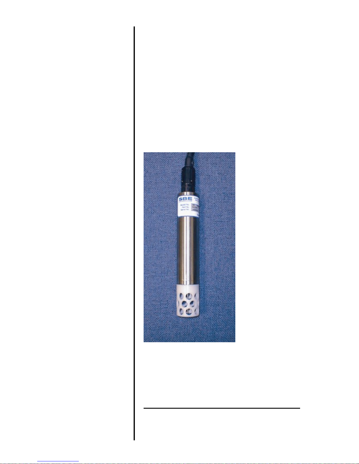
Shown below is a typical SBE 38 shipment.
connector and 9V battery
SBE 38 Digital
Oceanographic
Thermometer
Software Manuals and User Manual
9

6
Notes:
10
Manual revision 013 Section 2: Description of SBE 38 SBE 38
Section 2: Description of SBE 38
This section describes the functions and features of the SBE 38, including
specifications and dimensions.
System Description
Sophisticated A/D acquisition electronics, ultra-stable thermistor, and state-ofthe-art calibration provide the standards-level performance of an expensive
AC bridge and platinum thermometer at a small fraction of the cost. The
SBE 38 is unaffected by shock and vibration, has high accuracy and stability,
and is easy to use. It has a rugged, corrosion-proof, 10,500 meter (34,400 foot)
titanium pressure housing. Real-time temperature data is transmitted in ASCII
characters (in °C or raw counts) via an RS-232 or optional RS-485 serial
interface for display or logging by PC or data logger.
The SBE 38’s measurement range is -5 to +35 °C. Absolute accuracy is better
than 0.001 °C (1 mK) and resolution is approximately 0.00025 °C (0.25 mK).
Each sensor includes certification that demonstrates drift of less than 0.001 °C
(1 mK) during a six-month period.
Applications include calibration baths, oceanographic/aquatic research, and
environmental monitoring.
The SBE 38 operates in one of three ways:
• RS-232 (full duplex) with one SBE 38 connected to the interface
• RS-485 (half duplex) with one SBE 38 connected to the interface
• RS-485 (half duplex) with several RS-485 sensors sharing one pair
of wires
On power-up, the SBE 38 reads its EEPROM, which includes calibration
coefficients and other setup information. As programmed, the SBE 38 samples
and transmits temperature continuously, or waits for a command to begin
sampling. Note that for RS-485 applications with several sensors sharing one
pair of wires, the SBE 38 cannot sample continuously.
The SBE 38 is frequently integrated as a remote temperature sensor with one
of our thermosalinograph instruments (SBE 21 Thermosalinograph or SBE 45
MicroTSG), to provide accurate sea surface temperature. See the manuals for
those instruments for integration information.
• Help files provide detailed
information on the software.
• Separate software manuals on
CD-ROM contain detailed
information on Seasave V7 and
SBE Data Processing.
• Sea-Bird supplies the current
version of our software when you
purchase an instrument. As software
revisions occur, we post the revised
software on our FTP site. See our
website (www.seabird.com) for the
latest software version number, a
description of the software changes,
and instructions for downloading the
software from the FTP site.
The SBE 38 is supplied with a powerful Win 2000/XP software package,
SEASOFT V2, which includes:
• SEATERM terminal program for easy communication.
• Seasave V7 real-time data acquisition and SBE Data Processing
post-processing programs –Seasave V7 and SBE Data Processing can be
used to view and process the entire data stream, including data from the
SBE 38, when the SBE 38 is integrated with one of the following -
- SBE 21 or 45 thermosalinograph;
- SBE 16plus, 16plus V2, or 16plus-IM V2 SEACAT C-T Recorder; or
SBE 19plus V2 SEACAT CTD Profiler.

Manual revision 013 Section 2: Description of SBE 38 SBE 38
7
°
= (0.133 * NAvg) + 0.339
Note:
Specifications
Measurement
Range
-5 to +35 °C
11
If the SBE 38 is sampling data
and the voltage is less than
6.5 volts for 10 consecutive
scans, the SBE 38 halts sampling
and displays a low battery
indication in the data.
Initial Accuracy 1
Typical Stability
Resolution
Calibration
Response Time 2
Self-Heating
Error
RMS Noise
(at temperature
equivalent of 8.5 °C)
External Power
Materials
± 0.001 °C (1 mK)
0.001 °C (1 mK) in 6 months, certified
0.00025 °C (0.25 mK)
-1 to +32 °C
500 milliseconds
less than 200 µK
NAvg Noise (
C)
1 0.000673
2 0.000408
4 0.000191
8 0.000133
16 0.000081
32 0.000052
Note:
NAvg = number of A/D cycles per sample.
Interval between samples (seconds)
RS-232 (standard):
8 – 15 VDC at 15 milliamps average
RS-485 half-duplex (optional):
8 – 15 VDC at 10 milliamps average
Titanium pressure case rated at
10,500 meters (34,400 feet)
Weight
Notes:
1
NIST-traceable calibration applying over the entire range.
2
Time to reach 63% of final value following a step change in temperature.
In water: 0.5 kg (1.2 lbs)
In air: 0.9 kg (2.0 lbs)

8
Pin Signal
12
Manual revision 013 Section 2: Description of SBE 38 SBE 38
Dimensions and End Cap Connector
The SBE 38 is available with a 4-pin XSG-4-BCL-HP-SS or optional
MCBH-4MP (WB), TI (3/8” length base, ½-20 thread) (wet-pluggable)
external connector.
1 Common
2 RS-232 Receive or RS-485 A
3 RS-232 Transmit or RS-485 B
4 Power
Manual revision 013 Section 3: Preparing SBE 38 for Deployment SBE 38
9
Cable
Locking
Notes:
Section 3:
Preparing SBE 38 for Deployment
This section describes the software installation and the pre-check procedure
for preparing the SBE 38 for deployment.
Installing Software
Sea-Bird recommends the following minimum system requirements for
• Help files provide detailed
information on the software.
Separate software manuals on the
CD-ROM contain detailed
information on Seasave V7 and
SBE Data Processing.
• It is possible to use the SBE 38
without the SEATERM terminal
program by sending direct
commands from a dumb terminal or
terminal emulator, such as Windows
HyperTerminal.
• Sea-Bird supplies the current
version of our software when you
purchase an instrument. As software
revisions occur, we post the revised
software on our FTP site. See our
website (www.seabird.com) for the
latest software version number, a
description of the software changes,
and instructions for downloading the
software from the FTP site.
installing the software: Windows 2000 or later, 500 MHz processor,
256 MB RAM, and 90 MB free disk space for installation. Although
SEASOFT V2 was designed to work with a PC running Win 2000/XP;
extensive testing has not shown any compatibility problems when using the
software with a PC running Windows Vista or Windows 7 (32-bit).
If not already installed, install Sea-Bird software programs on your computer
using the supplied software CD:
1. Insert the CD in your CD drive.
2. Install software: Double click on SeasoftV2_date.exe (date is the date that
version of the software was created). Follow the dialog box directions to
install the software. The installation program allows you to install the
desired components. Install all the components, or just install SEATERM,
Seasave V7, and SBE Data Processing .
The default location for the software is c:\Program Files\Sea-Bird. Within that
folder is a sub-directory for each program.
13
Power and Communications Test
sleeve
Dummy plug
Test Setup
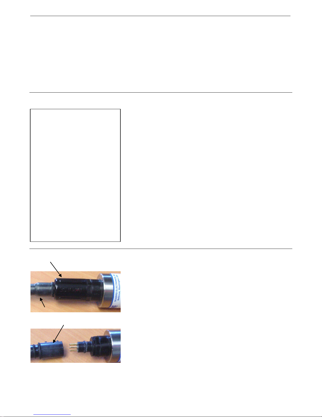
1. If applicable, remove locking sleeve and dummy plug from bulkhead
connector:
A. By hand, unscrew the locking sleeve from the SBE 38’s bulkhead
connector. If you must use a wrench or pliers, be careful not to
loosen the bulkhead connector instead of the locking sleeve.
B. Remove the dummy plug from the SBE 38’s bulkhead connector by
pulling the plug firmly away from the connector.
2. Install the Sea-Bird I/O cable on the SBE 38:
• XSG Connector (shown in photos) - Align the raised bump on the
side of the connector with the large pin (pin 1 - ground) on the
SBE 38.
• MCBH Connector (optional) – Align the pins.
3. Connect the I/O cable connector to your computer’s serial port.
4. Connect the I/O cable battery terminal clip to a 9-volt battery. Note that
the 9-volt battery supplied with the SBE 38 will provide approximately
50 hours of operation.

10
Note:
Note:
Note:
Status bar
Menus
Command/Data Echo Area
Toolbar
Instrument
Computer
Instrument
Baud rate, data bits,
SBE 38
14
Manual revision 013 Section 3: Preparing SBE 38 for Deployment SBE 38
Test
See SEATERM’s help files.
1. Double click on SeaTerm.exe. If this is the first time the program is used,
the setup dialog box may appear:
Select the instrument type (SBE 38) and the computer COM port for
communication with the SBE 38. Click OK.
2. The main screen looks like this:
There is at least one way, and as
many as three ways, to enter
a command:
• Manually type a command in
Command/Data Echo Area
• Use a menu to automatically
generate a command
• Use a Toolbar button to
automatically generate
a command
Once the system is configured and
connected (Steps 3 through 5
below), to update the Status bar:
• on the Toolbar, click Status; or
• from the Utilities menu, select
Instrument Status.
SEATERM sends the status
command, which displays in the
Command/Data Echo Area, and
updates the Status bar.
Capture
to file
status –
grayed
COM port
EPROM version
stop bits, and parity
out if not
capturing
• Menus – Contains tasks and frequently executed instrument
commands.
• Toolbar – Contains buttons for frequently executed tasks and
instrument commands. All tasks and commands accessed through the
Toolbar are also available in the Menus. To display or hide the
Toolbar, select View Toolbar in the View menu. Grayed out Toolbar
buttons are not applicable.
• Command/Data Echo Area – Echoes a command executed using a
Menu or Toolbar button, as well as the instrument’s response.
Additionally, a command can be manually typed in this area, from the
available commands for the instrument. Note that the instrument must
be awake for it to respond to a command (use Connect on the Toolbar
to wake up the instrument).
• Status bar – Provides status information. To display or hide the Status
bar, select View Status bar in the View menu.

Manual revision 013 Section 3: Preparing SBE 38 for Deployment SBE 38
11
Toolbar
Button
Equivalent
Command*
Re-establish communications with SBE 38.
(press Enter
Display instrument setup and status (number of
Coefficients
Display calibration coefficients.
DC
Capture instrument responses on screen to file.
Status bar.
Free computer COM port used to communicate
another program.
and SBE 38
Interface for communication
SBE 38
Notes:
Following are the Toolbar buttons applicable to the SBE 38:
Description
15
Connect
Capture
Disconnect
*See Command Descriptions in Section 4: Deploying and Operating
RS-232 SBE 38.
3. In the Configure menu, select SBE 38. The dialog box looks
like this:
Computer COM port, baud rate,
data bits, and parity for
communication between computer
Status
Computer responds with S> prompt.
A/D cycles per sample, sampling status, etc.).
File has .cap extension. Press Capture again to
turn off capture. Capture status displays in
with SBE 38. COM port can then be used by
between computer and
key)
DS
—
—
• SEATERM’s baud rate must be the
same as the SBE 38 baud rate (set
with Baud=). Baud= is factory-set to
9600, but can be changed by the user
(see Command Descriptions in
Section 4: Deploying and Operating
RS-232 SBE 38).
• When you click OK, SEATERM saves
the Configuration Options settings to
the SeaTerm.ini file in your Windows
directory. SeaTerm.ini contains the last
saved settings for each instrument.
When you open SEATERM and select
the desired instrument (SBE 38, 39,
etc.) in the Configure menu, the
Configuration Options dialog box
shows the last saved settings for that
instrument.
Make the selections in the Configuration Options dialog box:
• COMM Port: COM 1 through COM 10, as applicable
• Baud Rate: 9600 (documented on Configuration Sheet)
• Data Bits: 8
• Parity: None
• Mode: RS-232 (Full Duplex) or RS-485 (Half Duplex)
Click OK to save the settings.

12
Note:
16
Manual revision 013 Section 3: Preparing SBE 38 for Deployment SBE 38
4. In the Communications menu, select Options / Cycle baud
when connecting.
5. Click Connect on the Toolbar. SEATERM tries to connect to the SBE 38
at the baud set in Step 3. If it cannot, it cycles through all other possible
baud rates to try to connect. When it connects, the display looks like this:
SBE 38 V 1.4 S/N 0090 (this line may not appear)
S>
This shows that correct communications between the computer and the
SBE 38 has been established.
If the system does not provide the S> prompt:
• Click Connect again.
• Verify the correct instrument was selected in the Configure menu and
the settings were entered correctly in the Configuration Options
dialog box. Note that the baud rate’s factory setting is documented on
the Configuration Sheet in this manual.
• Check cabling between the computer and the SBE 38.
6. Display SBE 38 status information by clicking Status on the Toolbar. The
display looks like this:
See Appendix III: RS-485 Interface
for details on sending commands to
an SBE 38 with optional RS-485
interface.
SBE 38 V 1.4 S/N = 0090
NAVG=1
Not sampling data
Automatically start sampling on power up
Default interface is RS-232
7. Command the SBE 38 to take a sample by typing TS and pressing the
Enter key. The display looks like this if the output format was set to
converted data (Format=C) with 4 digits to the right of the decimal place
(Digits=4):
23.7658
where 23.7658 = temperature in degrees Celsius
This number should be reasonable; i.e., room temperature.
The SBE 38 is ready for programming and deployment.

Manual revision 013 Section 4: Deploying and Operating RS-232 SBE 38 SBE 38
13
Example: (user input in bold)
S>TS
Note:
Section 4:
Deploying and Operating RS-232 SBE 38
This section includes:
See Appendix III: RS-485 Interface
for details on deploying and
operating an SBE 38 with optional
RS-485 interface.
Sampling Modes
• system operation description, including example sets of
operation commands
• baud rate, cable length, and power limitations
• detailed command descriptions
• data formats
• instructions for deploying and recovering the SBE 38
The SBE 38 has two sampling modes:
• Polled Sampling – take a single sample on command
• Continuous Sampling – sample continuously; start when power is applied
or on command, depending on the setup
Descriptions and examples follow for an SBE 38 with RS-232 Interface. Note
that the SBE 38’s response to each command is not shown in the examples.
Review the sampling modes and the commands described in Command
Descriptions before setting up your system.
Polled Sampling
The SBE 38 takes one sample of data on command. Transmission of data to
the computer is dependent on the particular command used.
17
Apply power and establish communications. Set up to average 4 measurements per sample and output converted
data with 3 digits after decimal place. Command SBE 38 to take a sample and send data to computer.
(Apply power and then click Connect on Toolbar.)
S>NAVG=4
S>FORMAT=C
S>DIGITS=3
S>DS (to verify setup)

14
Example: Continuous Sampling (user input in bold)
18
Manual revision 013 Section 4: Deploying and Operating RS-232 SBE 38 SBE 38
Example 1 AutoRun=N: Apply power and establish communications. Set up to average 4 measurements per sample and output
converted data with 3 digits after decimal place. Set up to wait for a command when power is applied. Remove power.
(Apply power and then click Connect on Toolbar.)
S>NAVG=4
S>FORMAT=C
S>DIGITS=3
S>AUTORUN=N
S>DS (to verify setup)
(Remove power.)
When ready to start sampling, apply power and establish communications. Send command to start sampling continuously,
outputting real-time data. When desired, send command to stop sampling.
(Apply power and then click Connect on Toolbar.)
S>GO
S>STOP (You may need to send Stop several times to interrupt sampling.)
Example 2 AutoRun=Y: Apply power and establish communication. Set up to average 4 measurements per sample and output
converted data with 3 digits after decimal place. Set up to automatically begin sampling when power is applied. Remove power.
(Apply power and then click Connect on Toolbar.)
S>NAVG=4
S>FORMAT=C
S>DIGITS=3
S>AUTORUN=Y
S>DS (to verify setup)
(Remove power.)
To start sampling, apply power. SBE 38 begins sampling continuously, outputting real-time data.
To stop sampling, remove power.
To change setup: apply power, and then stop sampling by command.
(Apply power)
(Press Enter key to get S> prompt)
S>STOP (You may need to send Stop several times to interrupt sampling.)
(Enter commands as desired to change setup.)
Continuous Sampling
The SBE 38 continuously samples and transmits real-time data.
Sampling is started by:
• Sending Go, or
• Setting AutoRun=Y. If AutoRun=Y, sampling automatically starts when
power is applied.
Sampling is stopped by:
• Sending Stop, or
• Removing power.

Manual revision 013 Section 4: Deploying and Operating RS-232 SBE 38 SBE 38
15
Maximum Cable Length (meters)
Maximum Baud Rate
800
1200
400
2400
200
4800
100
9600
Example 1 – For 18 gauge wire, what is maximum distance to transmit power to RS-232 SBE 38?
Note:
Baud Rate, Cable Length, and Power
On the ship, cables longer than 3 meters should be installed inside an earthed
metal conduit by a qualified electrician. This minimizes the potential for
external signals to disrupt communication and ensures that high voltage lines
(such as the sea cable) are sufficiently protected. Cables shorter than 3 meters
can be used without shielding when installing or bench testing the instrument.
Notes:
• Baud rate is set with Baud=
(see Command Descriptions in
this section).
• For RS-485, see Appendix III:
RS-485 Interface for
baud rate limitations.
Common wire resistances:
Gauge Resistance (ohms/foot)
12 0.0016
14 0.0025
16 0.0040
18 0.0064
19 0.0081
20 0.0107
22 0.0162
24 0.0257
26 0.0410
28 0.0653
Baud Rate and Cable Length
For RS-232, the length of cable that the SBE 38 can drive to transmit real-time
data is dependent on the baud rate. The allowable combinations are:
Power and Cable Length
There are two issues to consider:
• Limiting the IR loss to 1 volt; higher IR loss will prevent the
instrument from transmitting real-time data because of the difference in
ground potential.
• Supplying enough power at the power source so that sufficient power is
available at the instrument after considering IR loss.
Looking at each issue separately:
Limiting IR Loss to 1 Volt
The limit to cable length is typically reached when the maximum current times
the power common wire resistance is more than 1 volt, because the difference
in ground potential of the SBE 38 and ground controller prevents the SBE 38
from transmitting real-time data.
= 1 volt = IR
V
limit
Where
I = current required by SBE 38 (15 mA for RS-232; 10 mA for RS-485).
Maximum cable length = R
limit
/ wire resistance per foot
limit
19
Is this controlling factor for maximum cable length if wanting to transmit at 1200 baud?
R
= V
limit
For 18 gauge wire, resistance is 0.0064 ohms/foot.
Therefore, maximum cable length is 67 ohms / 0.0064 ohms/foot = 10417 feet = 3176 meters.
Note that 3176 meters > 800 meters (maximum distance SBE 38 can transmit data at 1200 baud), so IR loss is not
controlling factor for this example.
Example 2 – Same as above, but there are 4 SBE 38s powered from the same power supply.
R
limit
For 18 gauge wire, resistance is 0.0064 ohms/foot.
Therefore, maximum cable length is 17 ohms / 0.0064 ohms/foot = 2604 feet = 794 meters (cable length to SBE 38
furthest from power source).
/ I = 1 volt / 0.015 Amps = 67 ohms
limit
= V
/ I = 1 volt / (0.015 Amps * 4 SBE 38s) = 17 ohms
limit

16
20
Manual revision 013 Section 4: Deploying and Operating RS-232 SBE 38 SBE 38
Supplying Enough Power to SBE 38
Another consideration in determining maximum cable length is supplying
enough power at the power source so that sufficient voltage is available, after
the IR loss in the cable, to power the SBE 38.
Example 1 – For 18 gauge wire, what is maximum distance to transmit power to RS-232 SBE 38 if using 8.5 volt power
source to supply power? Is this controlling factor for maximum cable length if wanting to transmit at 1200 baud?
SBE 38’s input power specification is 8 – 15 volts. Therefore, a 0.5 volt IR drop (8.5 volts – 8 volts) would still provide
enough power to SBE 38.
V = IR 0.5 volts = (0.015 Amps) * (0.0064 ohms/foot * cable length) Cable length = 5208 ft = 1588 meters
Note that 1588 meters > 800 meters (maximum distance SBE 38 can transmit data at 1200 baud), so IR drop in power is
not controlling factor for this example.
Example 2 – Same as above, but there are 4 SBE 38s powered from the same power supply.
V = IR 0.5 volts = (0.015 Amps * 4 SBE 38s) * (0.0064 ohms/foot * cable length)
Cable length = 1302 ft = 397 meters (cable length to SBE 38 furthest from power source).
Note that 397 meters < 800 meters (maximum distance SBE 38 can transmit data at 1200 baud), so IR drop in power is
controlling factor for this example. Using a higher voltage power supply or a different wire gauge (12 or 14 gauge) would
provide sufficient power at SBE 38 to allow 800 meter cable length.

Manual revision 013 Section 4: Deploying and Operating RS-232 SBE 38 SBE 38
17
Example: (user input in bold).
Default interface is RS-232
Note:
Note:
Note:
Go
Notes:
Command Descriptions
This section describes commands and provides sample outputs. See
Appendix IV: RS-232 Command Summary for a summarized command list.
When entering commands:
• Input commands to the SBE 38 in upper or lower case letters and register
commands by pressing the Enter key.
• The SBE 38 sends ? CMD if an invalid command is entered.
• If the system does not return an S> prompt after executing a command,
press the Enter key to get the S> prompt.
Equivalent to Status on Toolbar.
Description in example includes, where applicable,
command used to modify parameter.
If the voltage is below 6.5 volts, the
following displays in response to DS:
WARNING: LOW BATTERY VOLTAGE!!
Status Command
DS Display status and setup parameters.
21
S>DS
SBE 38 V 1.4 S/N = 0090 (firmware version, serial number)
NAVG=1 (number of A/D cycles to average for each sample [NAvg=])
Not sampling data (sampling status)
Automatically start sampling on power up (sampling start-up mode [AutoRun=])
The SBE 38’s baud (set with Baud=)
must be the same as SEATERM’s
baud rate (set in Configure menu).
• The SBE 38 transmits data after it
has completed the previous sample
and before it starts the next sample.
• For continuous sampling with an
RS-485 interface, set NAvg > 30.
See Appendix III: RS-485 Interface.
After you send AutoRun=Y, to start
sampling immediately:
• Turn power off and then on again, or
• Send
(RS-232 or RS-485 interface [Interface=])
Setup Commands
Interface=x x=232: Set interface to RS-232.
x=485: Set interface to RS-485. See Appendix III:
RS-485 Interface for all details.
Baud=x x= baud rate (1200, 2400, 4800, 9600).
Default 9600.
Format=x x=C: Output converted data (°C).
x=R: Output raw data (counts).
Digits=x x= number of digits (0 – 6) to right of decimal point
for converted temperature (°C). Applicable only if
Format=C.
NAvg=x x= number of A/D cycles to average per sample
(1 – 127).
Time between samples (seconds)
= (0.133 * NAvg) + 0.339
(Time between samples for continuous sampling;
minimum time required for each polled sample.)
AutoRun=x x=N: Wait for a command when power is applied.
x=Y: Start continuous sampling automatically when
power is applied.
.

18
Example: Display coefficients for SBE 38 (user input in bold).
Notes:
Note:
Note:
Notes:
the status to low battery.
22
Manual revision 013 Section 4: Deploying and Operating RS-232 SBE 38 SBE 38
Sampling Commands
• To capture real-time data to a file,
do this before starting sampling:
1. Click Toolbar’s Capture button.
2. Enter desired file name in
dialog box. Capture status
displays in status bar at bottom
of screen.
• If the SBE 38 is sampling data and
the voltage is less than 6.5 volts for
ten consecutive scans, the
SBE 38 halts sampling and sets
These commands are used to request data from the SBE 38.
For all sampling commands:
• Output format is determined by Format= and Digits=.
• Number of A/D cycles per sample is defined by NAvg.
Go Start sampling data continuously, and transmit data
real-time.
Time between samples (seconds)
= (0.133 * NAvg) + 0.339
Stop Stop continuous sampling. Press Enter key to get
S> prompt before entering Stop.
You may need to send Stop several
times to get the SBE 38 to respond.
TS Take 1 sample and transmit data.
TH Take 1 sample and hold data in SBE 38 buffer.
SH Transmit data that was held in SBE 38 buffer.
SL Transmit data from last sample from
SBE 38 buffer.
SLT Transmit data from last sample from SBE 38
buffer, and then take 1 new sample and hold data
in buffer.
Calibration Coefficients Commands
DC Display calibration coefficients.
• Date shown is when calibration
was performed. Calibration
coefficients are initially factory-set
and should agree with Calibration
Certificate shipped with SBE 38.
• See individual Coefficient
Commands below for definitions of
the data in the example.
S>DC
SBE 38 V 1.4 S/N = 0090
Cal Date: 08-apr-96
A0 =-9.420702e-05
A1 = 2.937924e-04
A2 =-3.739471e-06
A3 = 1.909551e-07
Slope = 1.000000
Offset = 0.0000
Equivalent to Coefficients on Toolbar.
The individual Coefficient Commands listed below modify a particular
coefficient or date:
F = floating point number
S = string with no spaces
TCalDate=S
A0=F
A1=F
A2=F
A3=F
Slope=F F=Temperature slope (default 1.0)
Offset=F F=Temperature offset (°C) (default 0.0)
S=Temperature calibration date
F=Temperature A0
F=Temperature A1
F=Temperature A2
F=Temperature A3

Manual revision 013 Section 4: Deploying and Operating RS-232 SBE 38 SBE 38
19
Notes:
CAUTION:
Locking sleeve
I/O cable
Data Formats
Converted Data (Format=C)
• Each line of output is followed by
a carriage return and line feed.
• For converted data, leading zeros
for temperature output are
suppressed, except for one zero
to the left of the decimal point
(for example, 0.1034).
• See Appendix III: RS-485
Interface for data output format
for an SBE 38 with optional
RS-485 interface.
ttt.ttt
where:
t = temperature (degrees Celsius, ITS-90)
Number of digits to right of decimal point is defined by Digits=.
Raw Data (Format=R)
nnnnnn.n
where:
n= counts
Deployment
1. Install the I/O cable:
Do not use WD-40 or other
petroleum-based lubricants, as they
will damage the connector.
A. Lightly lubricate the inside of the cable connector with silicone
grease (DC-4 or equivalent).
B. XSG Connector (shown in photo) - Install the cable connector,
aligning the raised bump on the side of the connector with the large
pin (pin 1 - ground) on the SBE 38. Remove any trapped air by
burping or gently squeezing the connector near the top and moving
your fingers toward the end cap. OR
MCBH Connector (optional) – Install the cable connector,
aligning the pins.
C. Place the locking sleeve over the connector. Tighten the locking
sleeve finger tight only. Do not overtighten the locking sleeve and
do not use a wrench or pliers.
2. Mount the SBE 38.
3. Verify that the hardware and external fittings are secure.
4. Use one of the following sequences to start sampling:
• If AutoRun=N: Send Go to start sampling continuously now, or TS
or TH to take a single sample.
• If AutoRun=Y: Apply power to start sampling continuously now.
5. Deploy the SBE 38.
23

20
WARNING!
24
Manual revision 013 Section 4: Deploying and Operating RS-232 SBE 38 SBE 38
Recovery
If the SBE 38 stops working while
underwater, is unresponsive to
commands, or shows other signs of
flooding or damage, carefully
secure it away from people until you
have determined that abnormal
internal pressure does not exist or
has been relieved. Pressure housings
may flood under pressure due to dirty
or damaged o-rings, or other failed
seals. When a sealed pressure
housing floods at great depths and is
subsequently raised to the surface,
water may be trapped at the pressure
at which it entered the housing,
presenting a danger if the housing is
opened before relieving the internal
pressure. Instances of such flooding
are rare. However, a housing that
floods at 5000 meters depth holds
an internal pressure of more than
7000 psia, and has the potential to
eject the end cap with lethal force.
A housing that floods at 50 meters
holds an internal pressure of more
then 85 psia; this force could still
cause injury.
If you suspect the SBE 38 is flooded,
point it in a safe direction away from
people, and loosen the bulkhead
connector very slowly, at least 1 turn.
This opens an o-ring seal under the
connector. Look for signs of internal
pressure (hissing or water leak). If
internal pressure is detected, let it
bleed off slowly past the connector
o-ring. Then, you can safely remove
the end cap.
1. Use one of the following sequences to stop sampling:
• Press Enter key to get S> prompt, and then send Stop to stop
sampling continuously. OR
• Remove power.
2. Rinse the SBE 38 with fresh water, and dry thoroughly.

Manual revision 013 Section 5: Routine Maintenance and Calibration SBE 38
21
CAUTION:
Note:
Section 5: Routine Maintenance
and Calibration
This section reviews corrosion precautions, connector mating and
maintenance, and sensor calibration. The SBE 38’s accuracy is sustained
by the care and calibration of the sensor and by establishing proper
handling practices.
Corrosion Precautions
All exposed materials are titanium or plastic. No corrosion precautions are
required, but direct electrical connection of the SBE 38 housing to mooring or
other dissimilar metal hardware should be avoided. Rinse the SBE 38 with
fresh water after use and prior to storage.
25
Connector Mating and Maintenance
See Application Note 57: Connector
Care and Cable Installation.
Do not use WD-40 or other
petroleum-based lubricants, as they
will damage the connector.
Clean and inspect the connectors, cable, and dummy plug before every
deployment and as part of your yearly equipment maintenance. Inspect
connectors that are unmated for signs of corrosion product around the pins,
and for cuts, nicks or other flaws that may compromise the seal.
When remating:
1. Lightly lubricate the inside of the cable connector with silicone grease
(DC-4 or equivalent).
2. XSG Connector - Install the cable connector, aligning the raised bump on
the side of the plug/cable connector with the large pin (pin 1 - ground) on
the SBE 38. Remove any trapped air by burping or gently squeezing the
connector near the top and moving your fingers toward the end cap. OR
MCBH Connector (optional) - Install the cable connector, aligning
the pins.
3. Place the locking sleeve over the cable connector. Tighten the locking
sleeve finger tight only. Do not overtighten the locking sleeve and do
not use a wrench or pliers.
Verify that a cable is installed on the SBE 38 before deployment.

22
26
Manual revision 013 Section 5: Routine Maintenance and Calibration SBE 38
Sensor Calibration
Sea-Bird sensors are calibrated by subjecting them to known physical
conditions and measuring the sensor responses. Coefficients are then
computed, which may be used with appropriate algorithms to obtain
engineering units. The temperature sensor on the SBE 38 is supplied fully
calibrated, with coefficients printed on the Calibration Certificate (see back of
manual). These coefficients have been stored in the SBE 38’s EEPROM.
We recommend that the SBE 38 be returned to Sea-Bird for calibration.
The primary source of temperature sensor calibration drift is the aging of the
thermistor element. Sensor drift is not substantially dependent upon the
environmental conditions of use, and — unlike platinum or copper elements
— the thermistor is insensitive to shock.
Sea-Bird’s Calibration Methodology
The SBE 38 is calibrated in Sea-Bird’s state-of-the-art calibration laboratory,
which maintains primary temperature standards (water triple point [TPW] and
gallium melting point [GaMP] cells), ITS-90 certified and standards-grade
platinum resistance thermometers, and a low-gradient temperature bath.
Temperature is computed using the Steinhart-Hart polynomial for thermistors
(Steinhart and Hart, 1968; Bennett, 1972), which is based on thermistor
physics. The equation characterizes the non-linear temperature versus
resistance response of the sensor. Note that thermistors require individualized
coefficients to the Steinhart-Hart equation, because the thermistor material is
an individualized mix of dopants:
t90 = 1.0 - 273.15 * Slope + Offset [°C]
a0 + a1 * [ln(n)] + a2 * [ln
2
(n)] + a3 * [ln
where
n = SBE 38 raw output (counts).
3
(n)]

Manual revision 013 Glossary SBE 38
23
Note:
Glossary
PCB – Printed Circuit Board.
SBE 38 – High-accuracy digital oceanographic thermometer.
SBE Data Processing – Sea-Bird’s Win 2000/XP data processing
All Sea-Bird software listed was
designed to work with a computer
running Windows 2000/XP. Extensive
testing has not shown any compatibility
problems when using the software with
a computer running Windows Vista or
Windows 7 (32-bit).
software, which calculates and plots measured and derived variables.
SBE Data Processing can be used to view and process the entire data stream,
including data from the SBE 38, when the SBE 38 is integrated with one of
the following:
• SBE 21 or 45 thermosalinograph,
• SBE 16plus, 16plus V2, or 16plus -IM V2 C-T Recorder
• SBE 19plus V2 CTD Profiler
Scan – One data sample.
Seasave V7 – Sea-Bird’s Win 2000/XP software used to acquire, convert,
and display real-time or archived raw data. Seasave V7 can be used to view
and process the entire data stream, including data from the SBE 38, when the
SBE 38 is integrated with one of the following:
• SBE 21 or 45 thermosalinograph,
• SBE 16plus, 16plus V2, or 16plus -IM V2 C-T Recorder
• SBE 19plus V2 CTD Profiler
SEASOFT V2 – Sea-Bird’s complete Win 2000/XP software package, which
includes software for communication, real-time data acquisition, and data
analysis and display. SEASOFT V2 includes SEATERM, SeatermAF,
SeatermV2, Seasave V7, SBE Data Processing, and Plot39.
SEATERM – Sea-Bird’s Win 95/98/NT/2000/XP terminal program used to
communicate with the SBE 38.
27

24
28
Manual revision 013 Appendix I: Functional Description SBE 38
Appendix I: Functional Description
Sensor Interface
Temperature is acquired by applying an AC excitation to a hermetically sealed
VISHAY reference resistor and an ultra-stable aged thermistor with a drift rate
of less than 0.002°C per year. A 24-bit A/D converter digitizes the outputs of
the reference resistor and thermistor. AC excitation and ratiometric
comparison using a common processing channel avoids errors caused by
parasitic thermocouples, offset voltages, leakage currents, and reference errors.
Maximum power dissipated in the thermistor is 0.5 microwatts, and
contributes less than 200 µK of overheat error.
A raw count (ratio) is related to resistance measurements:
raw counts = 1048576 * (NT) / (NR)
where
NR = output from reference resistor
NT = thermistor output
The SBE 38’s output is computed from the raw count and the calibration
coefficients that are stored in EEPROM.
The number of acquisition cycles (raw counts) averaged per measurement is
user-programmable (NAvg=; see Section 4: Deploying and Operating
RS-232 SBE 38). Increasing the number of cycles per measurement increases
the time to acquire the measurement and the interval between measurements,
while reducing the RMS temperature noise from the sensor. The interval
between measurements is:
interval [seconds] = (0.133 * NAvg) + 0.339
where
NAvg = number of acquisition cycles per measurement
The SBE 38 transmits data after it has completed the previous sample and
before it starts the next sample.
Time to transmit data = (number of characters * 10 bits/character) / baud rate
where
number of characters is dependent on the output format. Include the decimal
point when counting characters; add 2 to the number of characters output, to
account for the carriage return and line feed at the end of each scan.
Settings
Calibration coefficients and setup parameters (Baud=, NAvg=, Interface=,
etc.) are written to EEPROM and are non-volatile. These settings do not
change if power is removed.
Manual revision 013 Appendix II: Electronics Disassembly/Reassembly SBE 38
25
Note:
from the chamber.
End cap
O-ring
Appendix II: Electronics
Disassembly/Reassembly
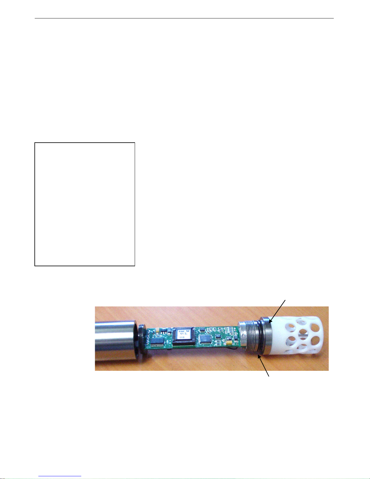
1. Remove the titanium end cap and electronics from the housing as follows:
A. Wipe the outside of the end cap and housing dry, being careful to
remove any water at the seam between them.
B. Unscrew the end cap.
C. Pull the end cap and attached electronics out of the housing. Note that
the PCB is electrically connected to the I/O connector.
D. Remove any water from the end cap O-ring and mating surfaces
Before delivery, a desiccant bag is
placed in the housing, and the
electronics chamber is filled with dry
Argon gas. These measures help
prevent condensation.
To ensure proper functioning:
1. Install a new desiccant bag
each time you open the
housing. If a new bag is not
available, see Application
Note 71: Desiccant Use and
Regeneration (drying).
2. If possible, dry gas backfill each
time you open the housing. If you
cannot, wait at least 24 hours
before redeploying, to allow the
desiccant to remove any moisture
2. Reinstall the end cap and electronics in the housing as follows:
inside the housing with a lint-free cloth or tissue.
E. Be careful to protect the O-ring from damage or contamination.
A. Remove any water from the O-ring and mating surfaces in the
housing with a lint-free cloth or tissue. Inspect the O-ring and mating
surfaces for dirt, nicks, and cuts. Clean as necessary. Apply a light
coat of O-ring lubricant (Parker Super O Lube) to O-ring and
mating surfaces.
B. Carefully fit the electronics into the housing.
C. Screw the end cap into the housing.
29

26
Example: Wake up all SBE 38s. Set up all SBE 38s to average 40 measurements per sample and output
Notes:
30
Manual revision 013 Appendix III: RS-485 Interface SBE 38
Appendix III: RS-485 Interface
Operation Description
Commands can be directed to one SBE 38 or globally to all SBE 38s. If
• IDReq=Y does not require a #ii
prefix. IDReq=N does require a #ii
prefix (#iiIDReq=N).
• For customers using their own
terminal program software:
Terminate all commands with CR
only, not CRLF.
converted data with 3 digits to the right of the decimal place. Command all SBE 38s to take a sample and hold
data in buffer, and then command each SBE 38 to transmit data from buffer. Repeat sampling sequence a number
of times. (user input in bold)
(Apply power and click Connect on Toolbar to wake up all SBE 38s.)
S>IDREQ=Y (command to require ID prefix)
S>#01NAVG=40 (set number of measurements per sample to 40 for SBE 38 with ID=01)
S>#02NAVG=40 (set number of measurements per sample to 40 for SBE 38 with ID=02)
S>#01FORMAT=C (set output format to converted data for SBE 38 with ID=01)
S>#02FORMAT=C (set output format to converted data for SBE 38 with ID=02)
S>#01DIGITS=3 (set number of digits to right of decimal point to 3 for SBE 38 with ID=01)
S>#02DIGITS=3 (set number of digits to right of decimal point to 3 for SBE 38 with ID=02)
S>#01DS (verify setup with status command for SBE 38 with ID=01)
S>#02DS (verify setup with status command for SBE 38 with ID=02)
S>GDATA (global command to all SBE 38s to take sample and hold data in buffer)
S>DATA01 (get data from buffer of SBE 38 with ID=01)
S>DATA02 (get data from buffer of SBE 38 with ID=02)
(Repeat GDATA through DATA02 as desired)
IDReq=Y, a command prefix (#ii) is used to direct commands to an SBE 38
with the same ID (ii = ID). Global commands do not use a prefix, regardless of
the setting for IDReq=, and are recognized by all SBE 38s attached to the
RS-485 interface.
An example follows for a system with two SBE 38s (IDs 01 and 02)
online. Note that the SBE 38’s response to each command is not shown
in the example. Review the commands described in Command Descriptions
and the example below before setting up your system.

Manual revision 013 Appendix III: RS-485 Interface SBE 38
27
Note:
S>@@#01DS
Note:
Example 1: Multiple RS-485 instruments on 1 pair of wires (user input in bold)
S>DS
Note:
Command Descriptions
RS-485 Commands
For reliable operation, all commands
may need to be preceded with two @
characters to clear the buffers.
Example (status command for
SBE 38 with ID=01):
GData and AData perform the same
function in the SBE 38. Both are
included here to provide compatibility
with RS-485 MicroCATs.
IDReq=Y does not require a #ii prefix.
IDReq=N does require a #ii prefix
(#iiIDReq=N).
Global Commands
Global commands are recognized by all SBE 38s attached to the
RS-485 interface.
TxDelay=x x= delay after SBE 38 transmits a reply until
SBE 38 transmitter is disabled
(1 – 500 milliseconds). Default 25 milliseconds.
RxDelay=x x= delay after SBE 38 receives a command
until SBE 38 transmitter is enabled
(1 – 500 milliseconds). Default 25 milliseconds.
GData Command all SBE 38s to take 1 sample and hold
data in SBE 38 buffer until receiving:
- DATAii;
- SH, SL, or SLT (if #iiIDReq=N); or
- #iiSH, #iiSL, or #iiSLT (if IDReq=Y).
AData Command all SBE 38s to take 1 sample and hold
data in SBE 38 buffer until receiving:
- DATAii;
- SH, SL, or SLT (if #iiIDReq=N); or
- #iiSH, #iiSL, or #iiSLT (if IDReq=Y).
Get Data Command
DATAii Get data obtained with GData or AData from
SBE 38 with ID = ii (ii = 0 -99).
ID Required Command
IDReq=Y Precede commands to individual SBE 38s with #ii,
where ii= ID (ii = 0 -99). Use this setting for
systems with multiple RS-485 instruments on
1 pair of wires. Note that the use of a prefix does
not apply to Global, Get Data, or ID commands.
#iiIDReq=N Do not precede commands to individual SBE 38s
with #ii. Use this setting for systems with only
1 SBE 38.
31
S>IDREQ=Y (command to require ID prefix)
S>#01NAVG=40 (set number of A/D cycles to average for SBE 38 with ID=01)
S>#02NAVG=40 (set number of A/D cycles to average for SBE 38 with ID=02)
S>#01DS (verify setup with status command for SBE 38 with ID=01)
S>#02DS (verify setup with status command for SBE 38 with ID=02)
Example 2: Only 1 SBE 38 on 1 pair of wires, with ID=01 (user input in bold)
S>#01IDREQ=N (command to not require ID prefix; note that #ii prefix is required)
S>NAVG=40 (set number of A/D cycles to average for SBE 38, no ID required as part of command)
(verify setup with status command for SBE 38, no ID required as part of command)

28
Notes:
Note:
32
Manual revision 013 Appendix III: RS-485 Interface SBE 38
ID Commands
Only one SBE 38 can be online when sending these commands.
ID? Display SBE 38 ID (ID = ii, where ii= 0-99) and
whether ID is required as a prefix for commands to
individual SBE 38s (see IDReq=).
*ID=ii Set SBE 38 ID to ii, where ii= 0-99. *ID= must be
sent twice, because the SBE 38 requests
verification. If more than one RS-485 instrument
is online when sending this command, all
instruments online will be set to same ID.
All Other Commands
All other commands (status, setup, sampling, and coefficients) are listed
in Section 4: Deploying and Operating RS-232 SBE 38 and in
Appendix IV: RS-232 Command Summary.
Notes on use of these commands for an SBE 38 with RS-485 interface:
• Effect of IDReq=:
IDReq=Y does not require a #ii prefix.
IDReq=N does require a #ii prefix
(#iiIDReq=N).
If IDReq=Y, precede these commands with #ii (ii = 0 – 99) to direct a
command to a particular SBE 38.
If #iiIDReq=N, do not precede these commands with #ii. This setting
works only for a system with one SBE 38.
• The RS-485 interface cannot accommodate multiple instruments
transmitting real-time data at the same time. Therefore, do not set
AutoRun=Y (start sampling continuously when power is applied) for a
system with more than one RS-485 instrument on a pair of wires.
Similarly, do not attempt to send Go to multiple SBE 38s on a pair of
wires, as the system cannot transmit a command to one instrument while
another instrument is transmitting real-time data.
• If planning to sample continuously: If AutoRun=Y (sample
continuously when power is applied) or using the Go command to start
sampling continuously, set NAvg= (A/D cycles to average per sample)
to a value greater than or equal to 30.
Data Formats
• Each line of output is followed by
a carriage return and line feed.
• For converted data, leading zeros
for temperature output are
suppressed, except for one zero
to the left of the decimal point
(for example, 0.1034).
Converted Data (Format=C)
Output from continuous sampling: ttt.ttt
Output from DATAii, #iiTS, TS, #iiSH, SH, #iiSL, SL, #iiSLT, or SLT:
ii, sssss, ttt.ttt
where:
t = temperature (°C, ITS-90)
(number of digits to right of decimal point is defined by Digits=)
ii = ID (0 – 99)
sssss = SBE 38 serial number
Raw Data (Format=R)
nnnnnn.n
where:
n = counts
Manual revision 013 Appendix III: RS-485 Interface SBE 38
29
Notes:
Optional
Note:
Wiring
When configured with the RS-485 interface, the SBE 38 can transmit data over
See Power and Cable Length in
Section 4: Deploying and Operating
RS-232 SBE 38 for cable limitations
related to the supply of power.
up to 1200 meters of 26 AWG twisted pair wire cable.
The MAX1483 transceivers used in the SBE 38 are designed for bi-directional
data communications on multi-point bus transmission lines. To minimize
reflections, terminate the line at both ends in its characteristic impedance.
Also, keep stub lengths off the main line as short as possible (although the slewrate-limited MAX1483 is more tolerant of imperfect termination than standard
RS-485 ICs).
RS-485
terminating
resistor
solder
points
33
Conversion of RS-232 to RS-485 or RS-485 to RS-232
• See Appendix II: Electronics
Disassembly / Reassembly to
access the PCB.
• Send Interface=232 or
Interface=485 to program
the SBE 38 to match the
wired configuration.
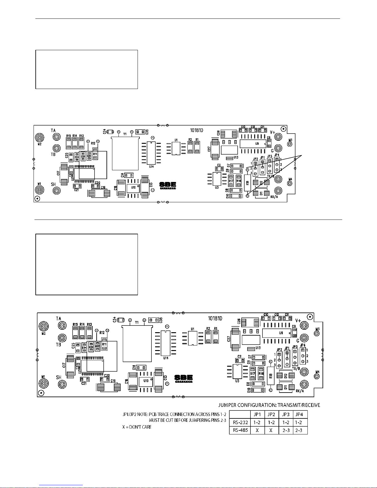
Sea-Bird supplies the SBE 38 with the correct jumper settings on the Printed
Circuit Board (PCB) for your ordered configuration (standard RS-232 or
optional RS-485). If desired, you can modify the jumper settings to change the
configuration:
Wiring: connect -
• Pin 2 (black) to RS-232 RX / RS-485 ‘A’
• Pin 3 (green) to RS-232 TX / RS-485 ’B’
30
Status
DS
Display status and setup parameters.
x=232: RS-232 interface.
x=485: RS-485 interface.
x= baud rate (1200, 2400, 4800, 9600).
x=C: Output converted data (°C).
x=R: Output raw data (counts).
x= number of digits (0 – 6) to right of
x= A/D cycles to average per sample
(1 – 127).
x=N: Wait for a command when
Go
Start continuous sampling now.
Stop continuous sampling.
before entering Stop.
TS
Take 1 sample and transmit data.
TH
Take 1 sample and hold data in buffer.
SH
Transmit data that was held in buffer.
Transmit data from last sample
Transmit data from last sample from
Display calibration coefficients; all
CalDate=S
S=Temperature calibration date.
A0=F
F=Temperature A0.
A1=F
F=Temperature A1.
A2=F
F=Temperature A2.
A3=F
F=Temperature A3.
Slope=F
F=Temperature slope (default 1.0).
Offset=F
F=Temperature offset (default 0.0).
Notes:
34
Manual revision 013 Appendix IV: RS-232 Command Summary SBE 38
Appendix IV: RS-232 Command Summary
CATEGORY COMMAND DESCRIPTION
• See Command Descriptions
in Section 4: Deploying and
Operating RS-232 SBE 38 for
detailed information and
examples.
• See Appendix III: RS-485
Interface for details on
deploying and operating
an SBE 38 with optional
RS-485 interface.
Setup
Sampling
Interface=x
Baud=x
Format=x
Digits=x
NAvg=x
AutoRun=x
Stop
SL
Default 9600.
decimal point for converted
temperature (°C). Applicable only if
Format=C
power applied.
x=Y: Start continuous sampling
automatically when power applied.
Press Enter key to get S> prompt
from buffer.
SLT
buffer, and then take 1 new sample and
hold data in buffer.
Coefficients
(F=floating point
number; S=string
with no spaces)
Date shown is
when calibration
was performed.
Calibration
coefficients are
initially factory-set
and should agree
with Calibration
Certificate shipped
with SBE 38.
DC
coefficients and dates listed below are
included. Use individual commands
below to modify a particular
coefficient or date.

Manual revision 013 Appendix V: Replacement Parts SBE 38
31
Appendix V: Replacement Parts
Part
Number
231361
30931
801376
801263
171888
17046.1
171398.1
Plastic temperature
sensor guard
O-ring,
Parker 2-214 N674-70
4-pin RMG-4FS to
9-pin DB-9S I/O cable
with battery snap,
2.4 m (8 ft) long
4-pin MCIL-4FS to
9-pin DB-9S I/O cable
with battery snap,
2.4 m (8 ft) long
25-pin DB-25S to 9-pin
DB-9P cable adapter
4-pin RMG-4SD-LP
dummy plug with
locking sleeve
4-pin MCIL-4FS dummy
plug with locking sleeve
Part Application Description
Screws to end cap to protect
temperature sensor
Placed in end cap groove for
watertight seal
From SBE 38 (XSG) to computer 1
From SBE 38 (wet-pluggable) to
computer
For use with computer with
DB-25 connector
For SBE 38 (XSG) connector 1
For SBE 38 (wet-pluggable)
connector
Quantity in
SBE 38
1
1
1
1
1
35

32
Manual
Version
006
03/03
Major rewrite: Remove DOS terminal program information and replace with SEATERM, add wet-
calibration equation information.
007
03/04
• Correct available bauds in command summary (remove 19200 & 3840).
Update Seaterm screens.
008
01/05
009
05/06
Add more information to Recovery Warning.
010
01/09
• PCB changed, connections and jumpers changed for conversion between RS-232 & RS-485.
011
04/09
Change spec for current to 15 mA for RS-232 version. Also change current for RS-485 to 10 mA.
012
01/10
date
013
03/11
36
Manual revision 013 Index SBE 38
Appendix VI: Manual Revision History
Date Description
pluggable connector option, correct calibration range to -1 to +32 (from -1 to +35 in old manual), correct
• Add power vs cable length information.
• Update cable list to 9-pin cable.
•
• Firmware 1.3 added 3 commands: slope= (default 1.0), offset=(default 0).
• Temperature calculation has slope & offset included in equation:
t = t * slope + offset
• Remove high range temperature calibration option (removed from price list).
• Update wet-pluggable connector information.
•
• Update for V2 Seacats –integration with 16plus V2, 16plus-IM V2, 19plus V2.
• Add information about compatibility with Vista.
• Remove information about DOS software.
• Update connector maintenance information for consistency with application note 57.
•
• Change Seasoft-Win32 to Seasoft V2, update file name to SeasoftV2_
• Add information required for CE certification, and add CE mark.
• Update SBE address.
• Add more information on RS-485 operation:
- Set NAvg > 30 for continuous sampling (using Go to start sampling, or if AutoRun=Y).
- IdReq=Y does not require #ii prefix, but IDReq=N does require #ii prefix (#iiIDReq=N).
- For customers using their own terminal program: terminate commands with CR (not CRLF)
Add information about compatibility with Windows 7
•
.exe.

Manual revision 013 Index SBE 38
33
Index
37
B
Baud rate · 15, 17
C
Cable length · 15
Calibration · 22
Calibration coefficients · 18
Command summary · 30
Commands
baud · 17
calibration coefficients · 18
data format · 17
descriptions · 17
get data · 27
global · 27
ID · 27, 28
ID required · 27
RS-485 · 27
sampling · 18
setup · 17
status · 17
Communication defaults · 11
Connector · 8, 21
Continuous sampling · 14
Corrosion precautions · 21
D
Data acquisition · 9
Data format · 17, 19, 28
Data processing · 9
Deployment
installation · 19
preparing for · 9
Description · 6
Desiccant · 25
Dimensions · 8
Disassembly / reassembly · 25
E
Electronics · 25
F
Flooded instrument · 20
Format · 17
data · 19, 28
Functional description · 24
G
Get data · 27
Global commands · 27
Glossary · 23
I
ID commands · 27, 28
M
Maintenance · 21
Manual revision history · 32
Modes · See Sampling modes
O
Operation description · 26
P
Parts
replacement · 31
Polled sampling · 13
Power · 15
Q
Quick start · 4
R
Real-time data acquisition · 9
Recovery · 20
Replacement parts · 31
Revision history · 32
RS-232 · 13, 17
conversion to RS-485 · 29
RS-485 · 17, 26
conversion to RS-232 · 29
wiring · 29
RS-485 commands · 27
S
Sampling · 18
Sampling modes · 13
continuous · 14
polled · 13
SBE Data Processing · 6, 9
Seasave · 6, 9
SEASOFT · 6, 9
SEATERM · 6, 9, 10
main screen · 10
toolbar buttons · 11
Sensor · 7
Serial interface · 17, 26
Settings · 24
Setup commands · 17
Software · 6
installation · 9
Specifications · 7
Status commands · 17
System description · 6
T
Terminal program · 9
Testing · 9
Thermistor · 24
L
Limited liability statement · 2
U
Unpacking SBE 38 · 5
V
Versions · 32

1
38
SBE 38 Digital Oceanographic Thermometer Reference Sheet
(see SBE 38 User’s Manual for complete details)
Interface
• RS-232 (standard) – one SBE 38 connected to the interface.
• RS-485 (optional) – one or more SBE 38s sharing one pair of wires.
Sampling Modes
• Polled sampling – SBE 38 takes one sample and transmits data.
• Continuous sampling – SBE 38 continuously samples and transmits data. As programmed, SBE 38 begins sampling
on power-up or waits for a command to begin sampling. Note that for RS-485 applications with several sensors
sharing one pair of wires, the SBE 38 cannot sample continuously.
For both polled and continuous sampling, the SBE 38 averages NAvg A/D cycles per sample. It outputs converted (°C) or
raw (counts) data, depending on Format=. For converted data, number of digits after the decimal place is defined
by Digits=.
Communication Setup Parameters
1. Double click on seaterm.exe.
2. Once main screen appears, in Configure menu select SBE 38. Input in dialog box:
• Serial Port: COM1 through COM10 are available
• Baud Rate: 9600 (or other if applicable)
• Data Bits: 8
• Parity: No Parity
• Mode: RS-232 (Full Duplex) or RS-485 (Half Duplex)
Deployment
1. Install I/O cable and locking sleeve.
2. Program SBE 38 for intended deployment (see other side of this sheet for Command Instructions and List):
A. Establish setup parameters.
B. Use one of following sequences to start sampling:
• If AutoRun=N: Go to start sampling continuously now, or TS or TH to take a single sample.
• If AutoRun=Y: Apply power to start sampling continuously now.
3. Mount SBE 38.
Reference Sheet Version #004, 03-23-11; Firmware Version 1.4 and later

2
Command Instructions and List
Status
DS
Display status.
x=232: RS-232 interface.
Baud=x
x= baud rate (1200, 2400, 4800, 9600). Default 9600.
x=C: Output converted data (°C).
Digits=x
x= digits (0 – 6) to right of decimal point for converted temperature (°C).
NAvg=x
x= A/D cycles to average per sample (1 – 127).
x=N: Wait for a command when power applied.
Go
Start continuous sampling now.
Stop
TS
Take 1 sample and transmit data.
TH
Take 1 sample and hold data in buffer.
SH
Transmit data that was held in buffer.
SL
Transmit data from last sample from buffer.
SLT
Transmit data from last sample from buffer, and then take 1 new sample and hold data in buffer.
DC
Display calibration coefficients.
CalDate=S
S=Temperature calibration date.
A0=F
F=Temperature A0.
A1=F
F=Temperature A1.
A2=F
F=Temperature A2.
A3=F
F=Temperature A3.
Slope=F
F=Temperature slope (default = 1.0).
Offset=F
F=Temperature offset (°C) (default = 0.0).
x= delay after SBE 38 transmits a reply until SBE 38 transmitter is disabled
(1 – 500 milliseconds). Default 25 milliseconds.
x= delay after SBE 38 receives a command until SBE 38 transmitter is enabled
GData or
AData
Command all SBE 38s to take 1 sample and hold data in SBE 38 buffer until receiving:
Get Data
DATAii
Get data obtained with GDATA or ADATA from SBE 38 with ID = ii (ii = 0 -99).
IDReq=Y
Precede commands to individual SBE 38s with #ii, where ii= ID (ii = 0 -99).
#iiIDReq=N
Do not precede commands to individual SBE 38s with #ii.
Display SBE 38 ID (ID = ii, where ii= 0-99) and whether ID is required as a prefix for
commands (see IDReq=).
Set SBE 38 ID to ii, where ii= 0-99. This command must be sent twice, because the computer
command, all instruments online will be set to same ID.
• Input commands to SBE 38 in upper or lower case letters and register commands by pressing the Enter key.
• SBE 38 sends ?CMD if invalid command is entered.
• If system does not return S> prompt after executing a command, press Enter key to get S> prompt.
Shown below are the commands. See the Manual for detailed descriptions and examples.
RS-232 Commands
CATEGORY COMMAND DESCRIPTION
39
Setup
Sampling
Coefficients
Interface=x
Format=x
AutoRun=x
x=485: RS-485 interface.
x=R: Output raw data (counts).
x=Y: Start continuous sampling automatically when power applied.
Stop continuous sampling. Press Enter key to get S> prompt before entering command.
RS-485 Commands
• See RS-232 Commands above for status, setup, sampling, and coefficients commands.
• If IDReq=Y, precede all above commands with #ii (ii = 0 – 99) to direct command to particular SBE 38.
If #iiIDReq=N, do not precede above commands with #ii (applies only for a system with 1 SBE 38).
• For reliable operation, all commands may need to be preceded with two @ characters to clear buffers.
• RS-485 interface cannot accommodate multiple instruments transmitting real-time data at same time. Therefore, do not set
AutoRun=Y (start sampling continuously when power is applied) for system with more than 1 RS-485 instrument on pair of
wires. Similarly, do not attempt to send Go command to multiple SBE 38s on pair of wires, as system cannot transmit command
to 1 instrument while another instrument is transmitting real-time data.
• If planning to sample continuously (AutoRun=Y or using Go to start sampling), set NAvg>30 (A/D cycles to average/sample).
CATEGORY COMMAND DESCRIPTION
TxDelay=x
Global
ID Required
ID
(only 1 SBE 38
can be online
when sending
these commands)
Reference Sheet Version #004, 03-23-11; Firmware Version 1.4 and later
RxDelay=x
ID?
*ID=ii
(1 – 500 milliseconds). Default 25 milliseconds.
DATAii; SH, SL, or SLT (if IDReq=N); or #iiSH, #iiSL, or #iiSLT (if IDReq=Y).
requests verification. If more than one RS-485 instrument is online when sending this

SBE 38 Configuration - S/N 0639...........................................................................................................................................................................................................................
1
SBE 38 Pressure Test Certificate - S/N 0639...............................................................................................................................................................................................................
2
SBE 38 Temperature Calibration - S/N 0639.................................................................................................................................................................................................................
3
..........................................................................................................................................................................................................................................................4
40
CALIBRATION SHEETS

Instrument Configuration:
Serial Number 37SI64195-8524
Pressure Sensor None
Firmware Version 3.0j
Memory 8192Kb
Interface Type RS-232
Conductivity Range 0-7 S/m
Baud Rate 9600, 8 data bits, no parity
Zero Conductivity 2491.031 Hz
Maximum Depth 7000 meters
41
SBE38
Digital Oceanographic Thermometer
Instrument Configuration:
Serial Number 3865557-0639
Firmware Version 1.4
Interface Type RS-232
Baud Rate 4800
Maximum Depth 10500 meters
CAUTION - The maximum deployment depth is
limited by the pressure housing to 10500m.

SBE Pressure Test Certificate
42
Sea-Bird Electronics, Inc.
13431 NE 20th St. Bellevue, Washington 98005 USA
Website: http://www.seabird.com
Phone: (425) 643-9866
FAX: (425) 643-9954
Email: seabird@seabird.com
Test Date:
Job Number:
3/22/2011
65557
Description
Customer Name
SBE-38 Digital Thermometer
EMS/FRANCE
SBE Sensor Information: Pressure Sensor Information:
Model Number:
Serial Number:
38
0639
Sensor Type:
Sensor Serial Number:
Sensor Rating:
None
None
0
Pressure Test Protocol:
Low Pressure Test: PSI Held For: Minutes
High Pressure Test: PSI Held For: Minutes
Passed Test:
40 15
10000 15
Tested By:
VG

Residual, (Degrees C)
SENSO
CALIBRA
ITS-90
a0 = -4
a1 = 2
a2 = -2
a3 = 1
BATH T
(ITS
-1.50
0.99
4.49
7.99
11.49
14.99
18.49
21.99
25.49
28.99
32.49
Tempera
R
C
-
t
13431
SERIAL NUM
TION DATE:
OEFFICIENTS
.502917e-00
.753940e-00
.452044e-00
.527765e-00
EMP
90)
010
990
990
990
990
990
990
990
990
990
990
ure ITS-90 = 1/{a
NE 20th
Phone:
SEA
425) 643 - 9866
(
B
6-Aug-11
2
6
4
6
7
INSTRUME
OUTPUT
832868
742792
634662
544072
467916
403680
349322
303177
263885
230325
201579
-BIRD E
S
ER: 063
0 + a1[
l
treet, Bellev
9
(n)] + a2
n
ECTRO
L
ue, Washi
Fax (425) 643
T
N
9
.
8
.
3
.
3
.
4
.
5
.
8
.
6
.
0
.
5
.
3
.
2
[
(n)] + a3
l
n
[
NICS, I
n
- 9954 Email: s
SBE 38
ITS-90
3
l
n
EMPERATUR
T
EMPERATURE
T
INST TEMP
(ITS-90)
-1.50009
0.99990
4.49988
7.99989
11.49991
14.99992
18.49990
21.99993
25.49986
28.99987
32.49993
(n)]} - 2
3.15
7
N
gton, 980
abird@seabird
e
E
-
-
-
-
(
°C)
C
.
5-2010 US
0
.co
m
CALIBRATIO
SCALE
ESIDUAL
R
ITS-90)
(
0.00001
0.00000
0.00002
0.00001
0.00001
0.00002
0.00000
0.00003
0.00004
0.00003
0.00003
DATA
N
43
A
0.02
0.01
0.00
-0.01
Residual
= instrument temp
erature - bath te
peratur
m
e
Date, Del
ta T (mdeg C)
26-Aug-11 0.00
-0.02
-5 0 5 10 15 20 25 30 35
Temperature, Degrees C

44
This page intentionally left blank.

45
Digital Oceanographic Thermometer
Sophisticated A/D acquisition electronics, ultra-stable thermistor, and state-ofthe-art calibration provide the standards-level performance of an expensive
AC bridge and platinum thermometer at a small fraction of the cost. The
SBE 38 is unaffected by shock and vibration, has high accuracy and stability,
and is easy to use. It has a rugged, corrosion-proof, 10,500 meter (34,400 foot)
titanium pressure housing. Real-time temperature data is transmitted in ASCII
characters (°C or raw counts) via an RS-232 or optional RS-485 serial interface for
display or logging by PC or data logger.
The SBE 38’s measurement range is -5 to +35 °C; absolute accuracy is better
than 0.001 °C (1 mK) and resolution is approximately 0.00025 °C (0.25 mK).
Each sensor includes certification that demonstrates drift of less than 0.001 °C
(1 mK) during a six-month period.
Applications include calibration baths, oceanographic/aquatic research, and
environmental monitoring. The SBE 38 is frequently integrated as a remote
temperature sensor with an SBE 21 Thermosalinograph or SBE 45 MicroTSG, to
provide accurate sea surface temperature. It can also be integrated as a secondary
temperature sensor with an SBE 16plus, 16plus-IM, 16plus V2, 16plus-IM V2, or
19plus V2 SEACAT CTD.
OPERATION
SBE 38
The SBE 38 operates in one of three modes:
• RS-232 (full duplex) with one SBE 38 connected to the interface
• RS-485 (half duplex) with one SBE 38 connected to the interface
• RS-485 (half duplex) with several RS-485 sensors sharing one pair of wires
On power-up, the SBE 38 reads its EEPROM, which includes calibration
coefficients and other setup information. As programmed, the SBE 38 samples
and transmits temperature continuously, or waits for a command. For RS-485
applications with several sensors sharing one pair of wires, the SBE 38 cannot
sample continuously.
MEASUREMENT METHOD
Temperature is determined by applying an AC excitation to reference resistances and an ultra-stable aged thermistor with
a drift rate of less than 0.002 °C per year. Each of the resulting outputs is digitized by a 24-bit A/D converter. The reference
resistor is a hermetically sealed VISHAY. AC excitation and ratiometric comparison using a common processing channel
removes measurement errors due to parasitic thermocouples, offset voltages, leakage currents, and gain errors. The
maximum power dissipated in the thermistor is 0.5 microwatts, and contributes less than 200 μK of overheat error.
A raw count (ratio) is related to resistance measurements:
raw counts = 1048576 * NT / NR
where NR is the output from the reference resistor and NT is the thermistor output.
The number of acquisition cycles (raw counts) averaged per sample is user-programmable. Increasing the number of cycles
per sample increases the time to acquire the sample and the interval between samples, while reducing the RMS temperature
noise from the sensor. The interval between samples is:
interval [seconds] = (0.133 * NAvg) + 0.339
where NAvg is the number of acquisition cycles per sample.
The SBE 38’s converted output is computed from the raw count and the calibration coefficients that are stored in EEPROM.
Sea-Bird Electronics, Inc.
13431 NE 20th Street, Bellevue, Washington 98005 USA
Website: http://www.seabird.com
E-mail: seabird@seabird.com
Fax: (425) 643-9954
Telephone: (425) 643-9866
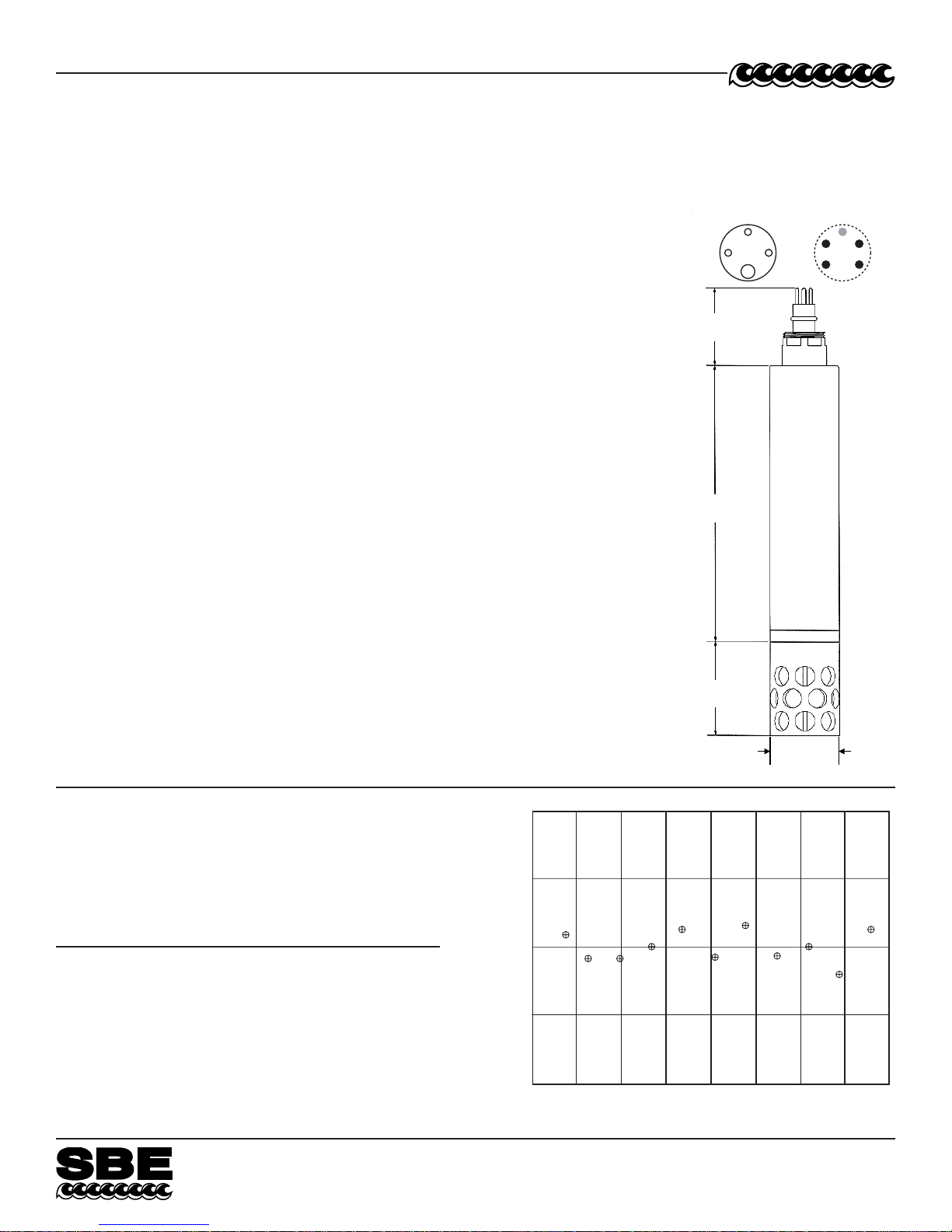
39.12 mm
(1.54 in.)
44.45 mm
(1.75 in.)
158.75 mm
(6.25 in.)
53.34 mm
(2.10 in.)
Optional connector:
Wet-Pluggable
MCBH-4MP (WB), TI
(3/8" length base,
1/2-20 thread)
1
2
4
3
1
432
Standard connector:
XSG-4-BCL-HP-SS
Pin Signal
1 Common
2 RS-232 Receive or RS-485 A
3 RS-232 Transmit or RS-485 B
4 Power
46
Digital Oceanographic Thermometer
CALIBRA TION
The SBE 38 is calibrated in Sea-Bird’s state-of-the-art calibration laboratory, which maintains
primary temperature standards (water triple point [TPW] and gallium melting point [GaMP]
cells), ITS-90 certified and standards-grade platinum resistance thermometers, and a lowgradient temperature bath.
Temperature is computed using the Steinhart-Hart polynomial for thermistors (Steinhart
and Hart, 1968; Bennett, 1972), which is based on thermistor physics. The equation
characterizes the non-linear temperature versus resistance response of the sensor. Note
that thermistors require individualized coefficients to the Steinhart-Hart equation, because
the thermistor material is an individualized mix of dopants:
= {[1.0 / (a0 + a1 * [ln(n)] + a2 * [ln
t
90L
where n is the SBE 38 output.
SPECIFICA TIONS
Interface and Power Requirements:
RS-232 (standard) Power: 8-15 VDC at 15 milliamps average
RS-485 half duplex (optional) Power: 8-15 VDC at 10 milliamps average
Housing: Titanium, rated at 10,500 meters (34,400 feet)
Weight:
In Air 0.9 kg (2.0 lbs)
In Water 0.5 kg (1.2 lbs)
Range: -5 to +35 °C
Initial Accuracy
Resolution: 0.00025 °C (0.25 mK)
Stability: 0.001 °C (1 mK) in six months, certified
Response Time2: 500 milliseconds
Self-heating Error: less than 200 μK
1 NIST-traceable calibration applying over the entire range.
2 Time to reach 63% of final value following a step change in temperature.
2
(n)] + a3 * [ln
1
: ± 0.001 °C (1 mK)
3
(n)])] - 273.15 } * Slope + Offset [°C]
SBE 38
ACTUAL CALIBRATION DATA for Sensor Number 80
CALIBRATION DATE: 02 September 1997
a0 = -2.809379e-05 a2 = -2.619655e-06
a1 = 2.783483e-04 a3 = 1.598734e-07
Bath Instrument Instrument Residual
Temperature Output Temperature (Instrument - Bath)
[°C] [n] [°C] [°C]
-1.52985 824162.7 -1.52983 0.00002
1.03108 733633.1 1.03106 -0.00002
4.60520 625547.1 4.60518 -0.00002
8.11169 536776.4 8.11169 -0.00000
11.61533 462132.6 11.61536 0.00003
15.17575 398167.3 15.17574 -0.00001
18.63931 345476.6 18.63934 0.00003
22.14032 300170.8 22.14031 -0.00001
25.66793 261276.6 25.66793 0.00000
29.13948 228549.1 29.13944 -0.00004
32.61481 200420.3 32.61484 0.00003
Sea-Bird Electronics, Inc.
13431 NE 20th Street, Bellevue, Washington 98005 USA
Website: http://www.seabird.com
0.0002
0.0001
RESIDUAL
(Degrees C)
0.0000
-0.0001
-0.0002
-5 0 5 10 15 20 25 30 35
TEMPERATURE (Degrees C)
04/09
E-mail: seabird@seabird.com
Fax: (425) 643-9954
Telephone: (425) 643-9866

1
A
47
Sea-Bird Electronics, Inc.
13431 NE 20
th
Street
Bellevue, WA 98005
US
Phone: (425) 643-9866
Fax: (425) 643-9954
E-mail: seabird@seabird.com
Web: www.seabird.com
APPLICATION NOTE NO. 42 Revised February 2010
ITS-90 TEMPERATURE SCALE
Beginning in January 1995, Sea-Bird's temperature metrology laboratory (based upon water triple-point and gallium melt cell,
SPRT, and ASL F18 Temperature Bridge) converted to ITS-90 (T90). These T90 standards are employed in calibrating all
Sea-Bird temperature sensors, and as the reference temperature used in conductivity calibrations.
The international oceanographic research community continues to use IPTS-68 (T68) for computation of salinity and other
seawater properties. Therefore, following the recommendations of Saunders (1990) and as supported by the Joint Panel on
Oceanographic Tables and Standards (1991), our software and our instrument firmware (for instruments that can calculate and
output salinity and other seawater properties directly) converts between T68 and T90 according to the linear relationship:
T
The use of T68 for salinity and other seawater calculations is automatic in our software and in those instruments that directly
output salinity and other seawater parameters.
Note: In our SEASOFT V2 suite of software programs, edit the CTD configuration (.con or .xmlcon) file to enter calibration
coefficients using the Configure Inputs menu in Seasave V7 (real-time data acquisition software) or the Configure menu in SBE
Data Processing (data processing software).
SBE 9plus (using SBE 3plus temperature sensor), 16, 19, 21, and 25 (using SBE 3F temperature sensor)
Beginning in January 1995, Sea-Bird temperature calibration certificates began listing a set of coefficients labeled g, h, i, j, and
F0, corresponding to ITS-90 (T90) temperatures. For user convenience and for historical comparison with older calibrations, the
certificates also continue to list a, b, c, d, and F0 coefficients corresponding to IPTS-68 (T68) temperatures. The T90 coefficients
result directly from T90 standards; the T68 coefficients are computed using the Saunders linear approximation.
SEASOFT supports entry of either the T90 or the T68 coefficients for these instruments. When selecting temperature as a
display/output variable, you must select which standard (T90 or T68) is to be used to compute temperature. SEASOFT
recognizes whether you have entered T90 or T68 coefficients in the configuration (.con or .xmlcon) file, and performs the
calculations accordingly, depending on which coefficients were used and which display variable type is selected.
• If g, h, i, j, F0 coefficients (T90) are entered in the configuration file and you select temperature display/output variable type
as T68, SEASOFT computes T90 temperature directly and multiplies it by 1.00024 to display or output T68.
• If a, b, c, d, and F0 coefficients (T68) are entered in the configuration file and you select temperature display/output variable
type as T90, SEASOFT computes T68 directly and divides by 1.00024 to display or output T90.
SBE 16plus, 16plus-IM, 16plus V2, 16plus-IM V2, 19plus, 19plus V2, 26plus, 35, 35RT, 37 (all), 38,
39 and 39-IM, 45, 49, 51, 52-MP, 53, and all higher numbered instruments
For these instruments, all first manufactured after the switch of our metrology lab to ITS-90, Sea-Bird provides only one set of
temperature calibration coefficients, based on the T90 standards. These instruments all have user-programmable internal
calibration coefficients, and can output data in engineering units (°C, S/m, dbar, etc. as applicable to the instrument). When
outputting temperature in engineering units, these instruments always output T90 temperatures.
• Instruments that can internally compute and then output salinity and other seawater parameters (for example,
SBE 37-SI) - Use of T68 for salinity and other seawater calculations is automatic; the instrument internally performs the
conversion between T90 and T68 according to the Saunders equation.
• Instruments supported in SEASOFT (for example, SBE 19plus V2) - Use of T68 for salinity and other seawater calculations
is automatic; the software performs the conversion between T90 and T68 according to the Saunders equation. When
selecting temperature as a display/output variable, you must select which standard (T90 or T68) is to be used to compute
temperature.
= 1.00024 * T90
68

A
48
Sea-Bird Electronics, Inc.
13431 NE 20
Bellevue, WA 98005
US
th
Street
Phone: (425) 643-9866
Fax: (425) 643-9954
E-mail: seabird@seabird.com
Web: www.seabird.com
Application Note 56 Revised February 2009
Interfacing to RS-485 Sensors
A few Sea-Bird instruments use the RS-485 protocol for transmitting setup commands to the instrument and receiving
data from the instrument. However, most personal computers (PCs) do not come with an RS-485 port. This Application
Note covers interfacing our RS-485 instruments with a PC by the following methods:
• Connecting the instrument to a USB RS-485 Adapter that plugs into an existing USB port on the PC, OR
• Connecting the instrument to an external RS-485/RS-232 Interface Converter that plugs into an existing RS-232
port on the PC, OR
• Installing an RS-485 Interface Card (and associated software) in the PC, and then connecting the instrument
directly to the new RS-485 port in the PC.
The use of these adapters/converters/cards is described below.
Note: Sea-Bird is providing information on adapters / converters / cards that we have tested with our instruments. Other
devices from these manufacturers, and devices from other manufacturers, may also be compatible with Sea-Bird
instruments. We recommend testing other devices with the instrument before deployment, to verify that there is no
problem.
USB RS-485 Adapter
A USB RS-485 adapter plugs into a USB port on the PC, and allows an RS-485 device to be connected through the
adapter. Sea-Bird tested an adapter from one manufacturer with our instruments, and verified compatibility:
National Instruments (www.ni.com) –
USB-485 with USB connector and RS-485 DB-9P connector
Follow this procedure to use the USB-485 Adapter:
1. Install the RS-485 driver software (provided with Adapter) on your PC before installing the Adapter.
2. Install the USB RS-485 Adapter.
3. Configure the USB port in your PC (directions are for a PC running Windows XP):
A. Right click on My Computer and select Properties.
B. In the System Properties dialog box, click on the Hardware tab. Click the Device Manager button.
C. In the Device Manager window, double click on Ports. Double click on the desired USB port.
D. In the Port Properties dialog box, click the Port Settings tab. Click the Advanced button.
E. In the Advanced Settings dialog box, set Transceiver Mode to 2 wire Auto. Verify that Bias Resistors Enabled
is not checked. Click OK. Then click OK in the Port Properties dialog box.
4. Disconnect the USB RS-485 Adapter from the PC, then plug it back in again. The new settings from Step 3 should
now be in effect.
5. Make a jumper cable (do not use a standard adapter cable) to connect the USB-485 Adapter to the instrument’s
I/O cable. Pin outs are shown for a Sea-Bird 9-pin (current production) or 25-pin (older production) I/O cable:
DB-9S
(connect to
USB-485 Adapter )
pin 1 common pin 5 common pin 7 common
pin 4 TX+ pin 3 'A' pin 2 'A'
pin 8 RX+ pin 3 'A' pin 2 'A'
pin 5 TX- pin 2 'B' pin 3 'B'
pin 9 RX- pin 2 'B' pin 3 'B'
(connect to Sea-Bird I/O cable PN 801385)
6. Run the terminal program software (see instrument manual for correct software for your instrument):
A. SEATERM: In SEATERM’s Configure menu, select the desired instrument. In the Configuration Options
dialog box, set Mode to RS-485 and set COMM Port to the appropriate USB port.
B. SeatermV2: In SeatermV2’s Instruments menu, select the desired instrument; Seaterm485 opens. In
Seaterm485’s Communications menu, select Configure. Set the Port to the appropriate USB port.
DB-9P
DB-25P
(connect to Sea-Bird I/O cable PN 801046)
1

External RS-485/RS-232 Interface Converter
An RS-485/RS-232 Interface Converter plugs into an RS-232 port on the PC, and allows an RS-485 device to be
connected through the Converter. Sea-Bird tested a Converter from one manufacturer with our instruments, and verified
compatibility:
Black Box (www.blackbox.com) –
IC520A-F with RS-232 DB-25 female connector and RS-485 terminal block connector
Follow this procedure to use the IC520A-F Converter:
1. Connect the Converter to the PC:
• If the PC has a 25-pin male RS-232 connector, plug the Converter directly into the PC connector.
• If the PC has a 9-pin male RS-232 connector, plug the Converter into a 25-pin to 9-pin adapter
(such as Black Box FA520A-R2 Adapter). Plug the 25-pin to 9-pin adapter into the PC.
2. On the Converter, measure the voltage between XMT+ and ground and between XMT- and ground.
Connect whichever has the highest voltage to RS-485 ‘A’ and the other to RS-485 ‘B’. The ground terminal can be
left unconnected.
RS-485 Interface Card and Port in the PC
An RS-485 Interface Card installs in the PC, and allows an RS-485 device to be connected to the RS-485 port. When
using with a Sea-Bird instrument:
• RS-485 Transmitter - The Interface Card must be configured to automatically handle the RS-485 driver enable.
• Two-Wire Interface -
TX+ and RX+ on the Interface Card must be connector together and to ‘A’ on the instrument.
TX- and RX- on the Interface Card must be connected together and to ‘B’ on the instrument.
Note: Some Interface Cards have a jumper to make the connections internally, while for other Cards the connections
must be made in a jumper cable.
Sea-Bird tested two Interface Cards from one manufacturer with our instruments, and verified compatibility:
National Instruments (www.ni.com) -
AT-485/2
PCI-485/2
Follow this procedure to use the AT-485/2 or PCI-485/2 Interface Card:
1. Install the RS-485 driver software (provided with Interface Card) on your PC before installing the Interface Card.
2. Install the RS-485 Interface Card.
3. Configure the RS-485 Interface Card in your PC (directions are for a PC running Windows XP):
A. Right click on My Computer and select Properties.
B. In the System Properties dialog box, click on the Hardware tab. Click the Device Manager button.
C. In the Device Manager window, double click on Ports. Double click on the desired RS-485 port.
D. In the Communications Port Properties dialog box, click the Port Settings tab. Click the Advanced button.
E. In the Advanced Settings dialog box, set Transceiver Mode to 2 wire TxRdy Auto. Click OK. Then click OK
in the Communications Port Properties dialog box.
4. Make a jumper cable (do not use a standard adapter cable) to connect the Interface Card to the instrument’s I/O
cable. Pin outs are shown for a Sea-Bird 9-pin (current production) or 25-pin (older production) I/O cable:
DB-9S
(connect to PC)
pin 1 common pin 5 common pin 7 common
pin 4 TX+ pin 3 'A' pin 2 'A'
pin 8 RX+ pin 3 'A' pin 2 'A'
pin 5 TX- pin 2 'B' pin 3 'B'
pin 9 RX- pin 2 'B' pin 3 'B'
(connect to Sea-Bird I/O cable PN 801385)
5. Run the terminal program software (see instrument manual for correct software for your instrument):
A. SEATERM: In SEATERM’s Configure menu, select the desired instrument. In the Configuration Options
dialog box, set Mode to RS-485 and set COMM Port to the appropriate RS-485 port.
B. SeatermV2: In SeatermV2’s Instruments menu, select the desired instrument; Seaterm485 opens. In
Seaterm485’s Communications menu, select Configure. Set the Port to the appropriate RS-485 port.
DB-9P
DB-25P
(connect to Sea-Bird I/O cable PN 801046)
49
2

1
A
50
Sea-Bird Electronics, Inc.
13431 NE 20
th
Street
Bellevue, WA 98005
US
Phone: (425) 643-9866
Fax: (425) 643-9954
E-mail: seabird@seabird.com
Web: www.seabird.com
APPLICATION NOTE NO. 57 Revised February 2010
Connector Care and Cable Installation
This Application Note describes the proper care of connectors and installation of cables for Sea-Bird instruments.
The Application Note is divided into three sections:
• Connector Cleaning and Inspection, and Cable / Dummy Plug Installation
• Locking Sleeve Installation
• Cold Weather Tips
Note: All photos in this Application Note show standard Impulse XSG/AG connectors. Except as noted, all
procedures apply to standard XSG/AG connectors as well as to optional wet-pluggable MCBH connectors.
Connector Cleaning and Inspection, and Cable / Dummy Plug Installation
Clean and inspect connectors, cables, and dummy plugs:
• Before every cruise.
• During the cruise – This is a good practice if you have a few days of down time between casts.
• After every cruise – This is the best way to find and remove any corrosion on connector pins before severe
corrosion develops.
• As part of your yearly equipment maintenance.
Follow this procedure:
1. Carefully clean the bulkhead connector and the inside of the mating cable’s boot or the dummy plug with a Kim
wipe. Remove all grease, hair, dirt, and other contamination.
Clean bulkhead
connector
2. Inspect the connector and cable boot or dummy plug:
A. Inspect the pins on the bulkhead connector for signs of
corrosion. The pins should be bright and shiny, with no
discoloration. If the pins are discolored or corroded, clean
with alcohol and a Q-tip.
B. Inspect the bulkhead connector for chips, cracks, or other
flaws that may compromise the seal.
C. Inspect the cable boot or dummy plug for cuts, nicks,
breaks, or other problems that may compromise the seal.
Replace severely corroded or otherwise damaged connectors,
cables, and dummy plugs - contact Sea-Bird for instructions
and a Return Material Authorization (RMA) number.
Clean inside of cable
boot or dummy plug
Corroded pins on bulkhead connectors Connector on right has a missing pin
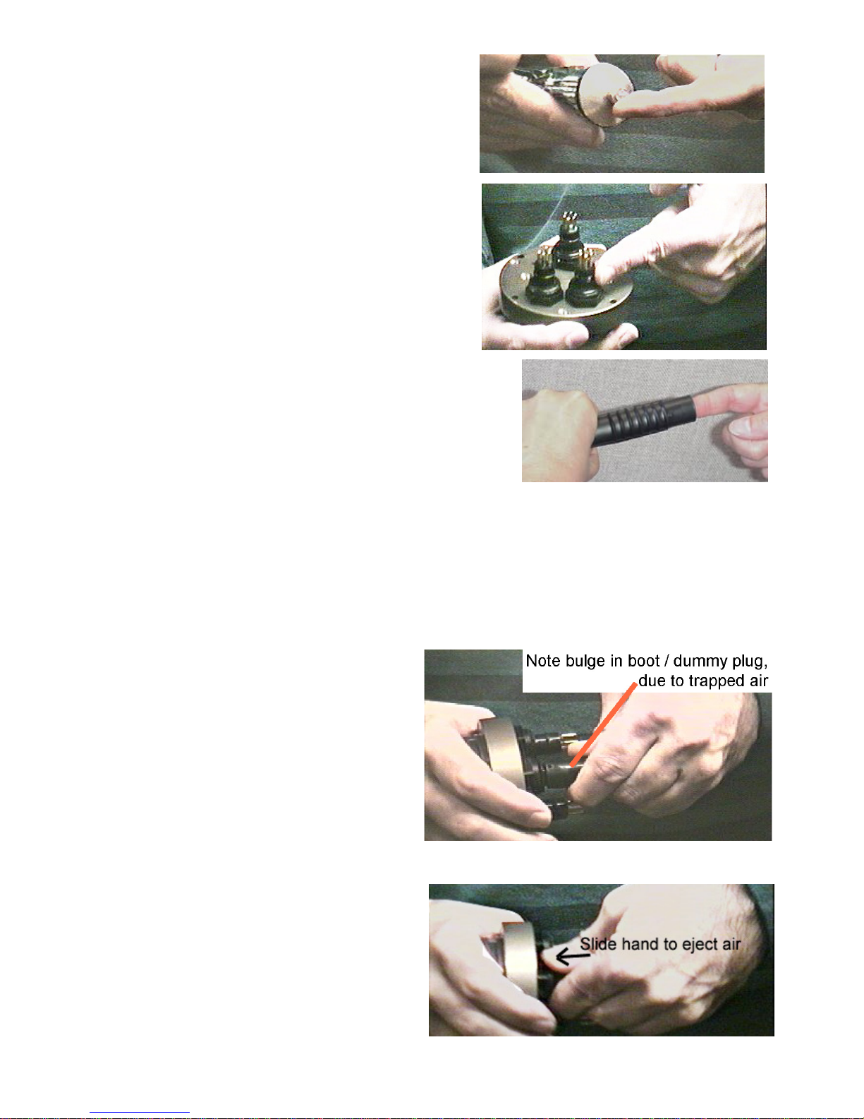
2
3. Using a tube of 100% silicone grease (Dow DC-4 or
equivalent), grease the bulkhead connector and the cable
boot or dummy plug.
CAUTION:
Do not use WD-40 or other petroleum-based lubricants,
as they will damage the connectors.
A. Squeeze the silicone grease -- approximately half the
size of a pea -- onto the end of your finger. Apply a
light, even coating of grease to the molded ridge around
the base of the bulkhead connector. The ridge looks like
an O-ring molded into the bulkhead connector base and
fits into the groove of the mating cable boot or dummy
plug.
B. Squeeze approximately half the size of a pea of the silicone
grease onto the end of your finger. Apply a light, even coating
of grease to the inside of the cable boot or dummy plug.
4. Standard XSG/AG connectors only: Align the bump on the cable boot or dummy plug with the large pin on the
bulkhead connector, and align the sockets with the pins.
Optional wet-pluggable MCBH connectors only: Align the non-conducting guide pin and the conducting pins
with the mating sockets.
• Do not twist the cable boot or dummy plug on the bulkhead connector; twisting can lead to bent pins,
which will soon break.
5. Push the cable boot or dummy plug all the way
onto the bulkhead connector.
• Standard XSG/AG connectors only: You may
note a bulge in the boot or dummy plug,
which is due to trapped air. There may be an
audible pop, which is good. With some newer
cables or dummy plugs, or in cold weather,
there may not be an initial audible pop.
6. Standard XSG/AG connectors only: After the cable
or dummy plug is mated, run your fingers along
the cable boot or dummy plug toward the bulkhead
connector, milking any trapped air out of the boot
or plug. You should hear the air being ejected.
CAUTION:
Failure to eject the trapped air will result in the
connector leaking.
51

3
52
Locking Sleeve Installation
After the cable boot or dummy plug is mated to the bulkhead connector, install the locking sleeve. The locking
sleeve secures the cable or dummy plug to the bulkhead connector and prevents them it being inadvertently
removed. Important points regarding locking sleeves:
• Tighten the locking sleeve by hand. Do not use a wrench or pliers to tighten the locking sleeve. Over-
tightening will gall the threads, which can bind the locking sleeve to the bulkhead connector. Attempting to
remove a tightly bound locking sleeve may instead result in the bulkhead connector actually unthreading from
the end cap. A loose bulkhead connector will lead to a flooded instrument. Pay particular attention when
removing a locking sleeve to ensure the bulkhead connector is not loosened.
• It is a common misconception that the locking sleeve provides watertight integrity. It does not, and continued
re-tightening of the locking sleeve will not fix a leaking connector.
• As part of routine maintenance at the end of a day’s casts, remove the locking sleeve, slide it up the cable, and
rinse the connection (still mated) with fresh water. This will prevent premature cable failure.
Locking sleeve
Cold Weather Tips
In cold weather, the cable or dummy plug may be hard to install and remove.
Removing a Frozen Cable Boot or Dummy Plug:
1. Wrap the cable boot or dummy plug with a washrag or other cloth.
2. Pour hot water on the cloth and let it sit for a minute or two. The cable boot or dummy plug should thaw and
become flexible enough to be removed.
Installing a Standard XSG/AG Cable or Dummy Plug:
When possible, install cables and dummy plugs in warm environments. If not, warm the cable boot or dummy plug
sufficiently so it is flexible. A flexible cable boot or dummy plug will install properly.
Note about Wet-Pluggable (MCBH) Connectors:
As an option, Sea-Bird offers wet-pluggable (MCBH) connectors in place of the standard Impulse XSG/AG
connectors. Wet-pluggable connectors have a non-conducting guide pin to assist pin alignment and require less
force to mate, making them easier to mate reliably under dark or cold conditions, compared to our standard
connectors. Wet-pluggable connectors may be mated in wet conditions; their pins do not need to be dried before
mating. By design, water on the connector pins is forced out as the connector is mated. However, they must not be
mated or un-mated while submerged. Like standard connectors, wet-pluggables need proper lubrication and require
care during use to avoid trapping water in sockets.
If desired, Sea-Bird can retrofit your existing instruments with wet-pluggable connectors; contact Sea-Bird for
pricing information.

1
A
53
Sea-Bird Electronics, Inc.
13431 NE 20
Bellevue, WA 98005
US
th
Street
Phone: (425) 643-9866
Fax: (425) 643-9954
E-mail: seabird@seabird.com
Web: www.seabird.com
APPLICATION NOTE NO. 68 Revised June 2009
Using USB Ports to Communicate with Sea-Bird Instruments
Most Sea-Bird instruments use the RS-232 protocol for transmitting setup commands to the instrument and receiving
data from the instrument. However, most newer PCs and laptop computers have USB port(s) instead of RS-232 serial
port(s).
USB serial adapters are available commercially. These adapters plug into the USB port, and allow one or more serial
devices to be connected through the adapter. Sea-Bird tested USB serial adapters from several manufacturers on
computers at Sea-Bird, and verified compatibility with our instruments. These manufacturers and the tested adapters
are:
• FTDI (www.ftdichip.com) -
“ChiPi” USB-RS232 Converter (model # FTDI UC232R-10).
Note: This adapter can also be purchased from Sea-Bird, as Sea-Bird part # 20200.
Drivers for this adapter can be found at http://www.ftdichip.com/Drivers/VCP.htm.
• IOGEAR (www.iogear.com) –
USB 1.1 to Serial Converter Cable (model # GUC232A).
Note: We have had several reports from customers that they could not communicate with their instrument using a
laptop computer and this adapter.
• Keyspan (www.keyspan.com) -
USB 4-Port Serial Adapter (part # USA-49WLC, replacing part # USA-49W)
Note: We have one report from a customer that he could not communicate with his instrument using a notebook
computer and this adapter. He was able to successfully communicate with the instrument using an XH8290 DSE
Serial USB Adapter (www.dse.co.nz).
• Edgeport (www.ionetworks.com) -
Standard Serial Converter Edgeport/2 (part # 301-1000-02)
Other USB adapters from these manufacturers, and adapters from other manufacturers, may also be compatible with
Sea-Bird instruments.
We recommend testing any adapters, including those listed above, with the instrument and the computer you will
use it with before deployment, to verify that there is no problem.
See Application Note 56: Interfacing to RS-485 Sensors for information on using a USB port to communicate with a
Sea-Bird instrument that communicates via RS-485 telemetry.
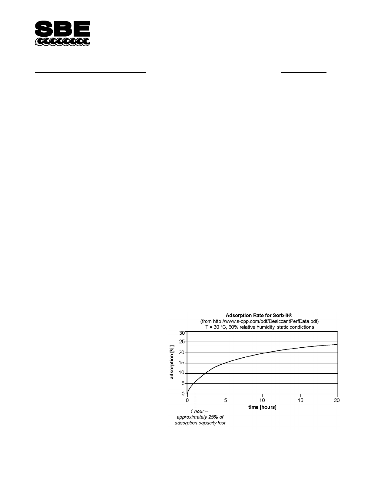
54
Sea-Bird Electronics, Inc.
13431 NE 20
Bellevue, WA 98005
USA
th
Street
Phone: (425) 643-9866
Fax: (425) 643-9954
E-mail: seabird@seabird.com
Web: www.seabird.com
APPLICATION NOTE NO. 71
Desiccant Use and Regeneration (drying)
This application note applies to all Sea-Bird instruments intended for underwater use. The application note covers:
• When to replace desiccant
• Storage and handling of desiccant
• Regeneration (drying) of desiccant
• Material Safety Data Sheet (MSDS) for desiccant
When to Replace Desiccant Bags
Before delivery of the instrument, a desiccant package is placed in the housing, and the electronics chamber is filled with dry
Argon. These measures help prevent condensation. To ensure proper functioning:
1. Install a new desiccant bag each time you open the housing and expose the electronics.
2. If possible, dry gas backfill each time you open the housing and expose the electronics. If you cannot, wait at least
24 hours before redeploying, to allow the desiccant to remove any moisture from the chamber.
What do we mean by expose the electronics?
• For most battery-powered Sea-Bird instruments (such as SBE 16, 16plus, 16plus V2, 16plus-IM, 16plus-IM V2,
17plus, 19, 19plus, 19plus V2, 25, 26, 26plus, 37-SM, 37-SMP, 37-IM, 37-IMP, 44, 53, 54, 55, Auto Fire Module
[AFM]), there is a bulkhead between the battery and electronics compartments. Battery replacement does not affect
desiccation of the electronics, as the batteries are removed without removing the electronics and no significant gas
exchange is possible through the bulkhead. Therefore, opening the battery compartment to replace the batteries does
not expose the electronics; you do not need to install a new desiccant bag in the electronics compartment each time you
open the battery compartment. For these instruments, install a new desiccant bag if you open the electronics
compartment to access the printed circuit boards.
• For the SBE 39, 39-IM, and 48, the electronics must be removed or exposed to access the battery. Therefore, install a
new desiccant bag each time you open the housing to replace a battery.
Storage and Handling
Testing by Süd-Chemie (desiccant’s manufacturer)
at 60% relative humidity and 30 °C shows that
approximately 25% of the desiccant’s adsorbing
capacity is used up after only 1 hour of exposure to
a constantly replenished supply of moisture in the
air. In other words, if you take a bag out of a
container and leave it out on a workbench for
1 hour, one-fourth of its capacity is gone before
you ever install it in the instrument. Therefore:
• Keep desiccant bags in a tightly sealed,
impermeable container until you are ready to
use them. Open the container, remove a bag,
and quickly close the container again.
• Once you remove the bag(s) from the sealed
container, rapidly install the bag(s) in the
instrument housing and close the housing.
Do not use the desiccant bag(s) if exposed to
air for more than a total of 30 minutes.
Revised March 2008
1

Regeneration (drying) of Desiccant
Replacement desiccant bags are available from Sea-Bird:
• PN 60039 is a metal can containing 25 1-gram desiccant bags and 1 humidity indicator card. The 1-gram bags
are used in our smaller diameter housings, such as the SBE 3 (plus, F, and S), 4 (M and C), 5T and 5P,
37 (-SI, -SIP, -SM, -SMP, -IM, and –IMP), 38, 39, 39-IM, 43, 44, 45, 48, 49, and 50.
• PN 31180 is a 1/3-ounce desiccant bag, used in our SBE 16plus, 16plus V2, 16plus-IM, 16plus-IM V2, 19plus,
19plus V2, 21, and 52-MP.
• PN 30051 is a 1-ounce desiccant bag. The 1-ounce bags are used in our larger diameter housings, such as the
SBE 9plus, 16, 17plus, 19, 25, 26, 26plus, 32, 53 BPR, 54, 55, AFM, and PDIM.
However, if you run out of bags, you can regenerate your existing bags using the following procedure provided by the
manufacturer (Süd-Chemie Performance Packaging, a Division of United Catalysts, Inc.):
MIL-D-3464 Desiccant Regeneration Procedure
Regeneration of the United Desiccants’ Tyvek Desi Pak
X-Crepe Desi Pak
®
or Sorb-It® bags can be accomplished by the following method:
1. Arrange the bags on a wire tray in a single layer to allow for adequate air flow around the bags
during the drying process. The oven’s inside temperature should be room or ambient temperature
(25 – 29.4 °C [77 – 85 °F] ). A convection, circulating, forced-air type oven is recommended for
this regeneration process. Seal failures may occur if any other type of heating unit or appliance
is used.
2. When placed in forced air, circulating air, or convection oven, allow a minimum of 3.8 to 5.1 cm
(1.5 to 2.0 inches) of air space between the top of the bags and the next metal tray above the bags.
If placed in a radiating exposed infrared-element type oven, shield the bags from direct exposure to the
heating element, giving the closest bags a minimum of 40.6 cm (16 inches) clearance from the heat
shield. Excessive surface film temperature due to infrared radiation will cause the Tyvek material to
melt and/or the seals to fail. Seal failure may also occur if the temperature is allowed to increase
rapidly. This is due to the fact that the water vapor is not given sufficient time to diffuse through the
Tyvek material, thus creating internal pressure within the bag, resulting in a seal rupture. Temperature
should not increase faster than 0.14 to 0.28 °C (0.25 to 0.50 °F) per minute.
3. Set the temperature of the oven to 118.3 °C (245 °F), and allow the bags of desiccant to reach
equilibrium temperature. WARNING: Tyvek has a melt temperature of 121.1 – 126.7 °C
(250 – 260 °F) (Non MIL-D-3464E activation or reactivation of both silica gel and Bentonite clay can
be achieved at temperatures of 104.4 °C [220 °F]).
4. Desiccant bags should be allowed to remain in the oven at the assigned temperature for 24 hours.
At the end of the time period, the bags should be immediately removed and placed in a desiccator jar or
dry (0% relative humidity) airtight container for cooling. If this procedure is not followed precisely,
any water vapor driven off during reactivation may be re-adsorbed during cooling
and/or handling.
5. After the bags of desiccant have been allowed to cool in an airtight desiccator, they may be removed
and placed in either an appropriate type polyliner tightly sealed to prevent moisture adsorption, or a
container that prevents moisture from coming into contact with the regenerated desiccant.
NOTE: Use only a metal or glass container with a tight fitting metal or glass lid to store the regenerated desiccant. Keep
the container lid closed tightly to preserve adsorption properties of the desiccant.
®
or Sorb-It® bags or United Desiccants’
55
2

56
Sud-Chemie Performance
Packaging
101 Christine Dr.
Belen, New Mexico 87002
Phone: (505) 864-6691
Fax: (505) 864-9296
ISO 9002 CERTIFIED
MATERIAL SAFETY DATA SHEET – August 13, 2002
SORB-IT®
Packaged Desiccant
SECTION I -- PRODUCT IDENTIFICATION
Trade Name and Synonyms: Silica Gel, Synthetic Amorphous Silica,
Silicon, Dioxide
Chemical Family: Synthetic Amorphous Silica
Formula: SiO2.x H2O
SECTION II -- HAZARDOUS INGREDIENTS
Components in the Solid Mixture
COMPONENT CAS No % ACGIH/TLV (PPM) OSHA-(PEL)
Amorphous
Silica
63231-67-4 >99 PEL - 20 (RESPIRABLE),
TLV – 5
LIMIT – NONE,
HAZARD IRRITANT
Synthetic amorphous silica is not to be confused with crystalline silica such as quartz,
cristobalite or tridymite or with diatomaceous earth or other naturally occurring forms of
amorphous silica that frequently contain crystalline forms.
This product is in granular form and packed in bags for use as a desiccant. Therefore, no
exposure to the product is anticipated under normal use of this product. Avoid inhaling
desiccant dust.
SECTION III -- PHYSICAL DATA
Appearance and Odor: White granules; odorless.
Melting Point: >1600 Deg C; >2900 Deg F
Solubility in Water: Insoluble.
Bulk Density: >40 lbs./cu. ft.
Percent Volatile by Weight @ 1750 Deg F: <10%.
3

Sud-Chemie Performance
Packaging
101 Christine Dr.
Belen, New Mexico 87002
Phone: (505) 864-6691
Fax: (505) 864-9296
ISO 9002 CERTIFIED
MATERIAL SAFETY DATA SHEET – August 13, 2002
SORB-IT®
Packaged Desiccant
SECTION IV -- FIRE EXPLOSION DATA
Fire and Explosion Hazard - Negligible fire and explosion hazard when exposed to heat
or flame by reaction with incompatible substances.
Flash Point - Nonflammable.
Firefighting Media - Dry chemical, water spray, or foam. For larger fires, use water spray
fog or foam.
Firefighting - Nonflammable solids, liquids, or gases: Cool containers that are exposed
to flames with water from the side until well after fire is out. For massive fire in enclosed
area, use unmanned hose holder or monitor nozzles; if this is impossible, withdraw from
area and let fire burn. Withdraw immediately in case of rising sound from venting safety
device or any discoloration of the tank due to fire.
SECTION V -- HEALTH HAZARD DATA
Health hazards may arise from inhalation, ingestion, and/or contact with the skin and/or
eyes. Ingestion may result in damage to throat and esophagus and/or gastrointestinal
disorders. Inhalation may cause burning to the upper respiratory tract and/or temporary or
permanent lung damage. Prolonged or repeated contact with the skin, in absence of
proper hygiene, may cause dryness, irritation, and/or dermatitis. Contact with eye tissue
may result in irritation, burns, or conjunctivitis.
First Aid (Inhalation) - Remove to fresh air immediately. If breathing has stopped, give
artificial respiration. Keep affected person warm and at rest. Get medical attention
immediately.
First Aid (Ingestion) - If large amounts have been ingested, give emetics to cause
vomiting. Stomach siphon may be applied as well. Milk and fatty acids should be
avoided. Get medical attention immediately.
First Aid (Eyes) - Wash eyes immediately and carefully for 30 minutes with running
water, lifting upper and lower eyelids occasionally. Get prompt medical attention.
First Aid (Skin) - Wash with soap and water.
57
4

58
Sud-Chemie Performance
Packaging
101 Christine Dr.
Belen, New Mexico 87002
Phone: (505) 864-6691
Fax: (505) 864-9296
ISO 9002 CERTIFIED
MATERIAL SAFETY DATA SHEET – August 13, 2002
SORB-IT®
Packaged Desiccant
NOTE TO PHYSICIAN: This product is a desiccant and generates heat as it adsorbs
water. The used product can contain material of hazardous nature. Identify that material
and treat accordingly.
SECTION VI -- REACTIVITY DATA
Reactivity - Silica gel is stable under normal temperatures and pressures in sealed
containers. Moisture can cause a rise in temperature which may result in a burn.
SECTION VII --SPILL OR LEAK PROCEDURES
Notify safety personnel of spills or leaks. Clean-up personnel need protection against
inhalation of dusts or fumes. Eye protection is required. Vacuuming and/or wet methods
of cleanup are preferred. Place in appropriate containers for disposal, keeping airborne
particulates at a minimum.
SECTION VIII -- SPECIAL PROTECTION INFORMATION
Respiratory Protection - Provide a NIOSH/MSHA jointly approved respirator in the
absence of proper environmental control. Contact your safety equipment supplier for
proper mask type.
Ventilation - Provide general and/or local exhaust ventilation to keep exposures below
the TLV. Ventilation used must be designed to prevent spots of dust accumulation or
recycling of dusts.
Protective Clothing - Wear protective clothing, including long sleeves and gloves, to
prevent repeated or prolonged skin contact.
Eye Protection - Chemical splash goggles designed in compliance with OSHA
regulations are recommended. Consult your safety equipment supplier.
SECTION IX -- SPECIAL PRECAUTIONS
Avoid breathing dust and prolonged contact with skin. Silica gel dust causes eye irritation
and breathing dust may be harmful.
5

Sud-Chemie Performance
Packaging
101 Christine Dr.
Belen, New Mexico 87002
Phone: (505) 864-6691
Fax: (505) 864-9296
ISO 9002 CERTIFIED
MATERIAL SAFETY DATA SHEET – August 13, 2002
SORB-IT®
Packaged Desiccant
* No Information Available
HMIS (Hazardous Materials Identification System) for this product is as
follows:
Health Hazard 0
Flammability 0
Reactivity 0
Personal Protection HMIS assigns choice of personal protective equipment to the
customer, as the raw material supplier is unfamiliar with the
condition of use.
The information contained herein is based upon data considered true and accurate. However, United Desiccants makes no warranties
expressed or implied, as to the accuracy or adequacy of the information contained herein or the results to be obtained from the use
thereof. This information is offered solely for the user's consideration, investigation and verification. Since the use and conditions of
use of this information and the material described herein are not within the control of United Desiccants, United Desiccants assumes no
responsibility for injury to the user or third persons. The material described herein is sold only pursuant to United Desiccants' Terms
and Conditions of Sale, including those limiting warranties and remedies contained therein. It is the responsibility of the user to
determine whether any use of the data and information is in accordance with applicable federal, state or local laws and regulations.
59
6

60

61

62
WARRANTY POLICY 2010
PRODUCT WARRANTY
5-YEAR LIMITED WARRANTY (NEW PRODUCTS)
For a period of five years after the date of original shipment from our factory, products manufactured by
Sea-Bird are warranted to function properly and be free of defects in materials and workmanship. Should a Sea-Bird
instrument fail during the warranty period, return it freight pre-paid to our factory. We will repair it (or at our option,
replace it) at no charge, and pay the cost of shipping it back to you. Certain products and components have modified
coverage under this warranty as described below.
LIMITED WARRANTY ON SERVICE & REPAIRS
Service work, repairs, replacement parts and modifications are warranted to be free of defects in materials or
workmanship for the remainder of the original 5-year warranty or one year from the date of shipment from our factory
after repair or service, which ever is longer. Certain products and components have modified coverage under this
warranty as described below.
MODIFICATIONS / EXCEPTIONS / EXCLUSIONS
1. The SBE 43 DO sensor is warranted to function properly for 5 years. Under normal use however, the electrolyte in
an SBE 43 DO sensor will require replenishment after about 3 years (or longer, depending on conditions of use).
Anytime during the warranty period (typically after 3 years), the SBE 43 will be refurbished once without charge,
Return the sensor freight pre-paid to our factory. We will refurbish it for free (electrolyte refill, membrane
replacement, and recalibration) and pay the cost of shipping it back to you. Membrane damage or depletion of
electrolyte caused by membrane damage is not covered by this warranty.
2. The pH sensor electrode used in the SBE 18 pH sensor and SBE 27 pH/ORP sensor has a limited design life
caused by depletion of their chemical constituents during normal storage and use, and is covered under warranty
for the first 90 days only. Other components of the sensor (housing, electronics, etc.) are covered for 5 years.
3. Instruments or sensors manufactured by other companies are warranted only to the limit of the warranties provided
by their original manufacturers, typically 1 year. (example: fluorometers, transmissometers, PAR, optical
backscatter sensors, altimeters, etc.)
4. Water sample bottles manufactured by other companies, and PVC plastic bottle parts used to make Sea-Bird
Improved Sample Bottles are warranted only to the limit of the warranties provided by their original
manufacturers, typically one year. The mounting bracket (except stainless steel band clamp) used in Sea-Bird
Improved Sample Bottles is covered for 5 years.
5. Batteries, zinc anodes, anti-foulant devices, or other consumable/expendable items are not covered under this
warranty.
6. Electrical cables, dummy plugs, and stainless steel band clamps are warranted to function properly and be free of
defects in materials and workmanship for 1 year.
7. This warranty is void if in our opinion the instrument has been damaged by accident, mishandled, altered,
improperly serviced, or repaired by the customer where such treatment has affected its performance or reliability.
In the event of such misuse/abuse by the customer, costs for repairs plus two-way freight costs will be borne by the
customer. Instruments found defective should be returned to the factory carefully packed, as the customer will be
responsible for freight damage.
8. Incidental or consequential damages or costs incurred as a result of product malfunction are not the
responsibility of SEA-BIRD ELECTRONICS, INC.

WARRANTY ADMINISTRATION POLICY
Sea-Bird Electronics, Inc. and its authorized representatives or resellers provide warranty support only to the
original purchaser. Warranty claims, requests for information or other support, and orders for post-warranty repair
and service, by end-users that did not purchase directly from Sea-Bird or an authorized representative or reseller,
must be made through the original purchaser. The intent and explanation of our warranty policy follows:
1. Warranty repairs are only performed by Sea-Bird.
2. Repairs or attempts to repair Sea-Bird products performed by customers (owners) shall be called owner repairs.
3. Our products are designed to be maintained by competent owners. Owner repairs of Sea-Bird products will
NOT void the warranty coverage (as stated above) simply as a consequence of their being performed.
4. Owners may make repairs of any part or assembly, or replace defective parts or assemblies with
Sea-Bird manufactured spares or authorized substitutes without voiding warranty coverage of the entire product,
or parts thereof. Defective parts or assemblies removed by the owner may be returned to Sea-Bird for repair or
replacement within the terms of the warranty, without the necessity to return the entire instrument. If the owner
makes a successful repair, the repaired part will continue to be covered under the original warranty, as if it had
never failed. Sea-Bird is not responsible for any costs incurred as a result of owner repairs or equipment
downtime.
5. We reserve the right to refuse warranty coverage on a claim by claim basis based on our judgment and
discretion. We will not honor a warranty claim if in our opinion the instrument, assembly, or part has been
damaged by accident, mishandled, altered, or repaired by the customer where such treatment has affected its
performance or reliability.
6. For example, if the CTD pressure housing is opened, a PC board is replaced, the housing is resealed, and then it
floods on deployment, we do not automatically assume that the owner is to blame. We will consider a claim for
warranty repair of a flooded unit, subject to our inspection and analysis. If there is no evidence of a fault in
materials (e.g., improper or damaged o-ring, or seal surfaces) or workmanship (e.g., pinched o-ring due to
improper seating of end cap), we would cover the flood damage under warranty.
7. In a different example, a defective PC board is replaced with a spare and the defective PC board is sent to SeaBird. We will repair or replace the defective PC board under warranty. The repaired part as well as the
instrument it came from will continue to be covered under the original warranty.
8. As another example, suppose an owner attempts a repair of a PC board, but solders a component in backwards,
causing the board to fail and damage other PC boards in the system. In this case, the evidence of the backwards
component will be cause for our refusal to repair the damage under warranty. However, this incident will NOT
void future coverage under warranty.
9. If an owner's technician attempts a repair, we assume his/her qualifications have been deemed acceptable to the
owner. The equipment owner is free to use his/her judgment about who is assigned to repair equipment, and is
also responsible for the outcome. The decision about what repairs are attempted and by whom is entirely up to
the owner.
63

64
SOFTWARE WARRANTY
SOFTWARE LICENSE AGREEMENT
By downloading or installing any of our software, you expressly agree to the following:
Sea-Bird's SEASOFT
SEASOFT is protected by copyright laws and international copyright treaties, as well as other intellectual property
laws and treaties. All title and copyrights in and to SEASOFT and the accompanying printed materials, and any
copies of SEASOFT, are owned by Sea-Bird Electronics. There are no restrictions on its use or distribution,
provided such use does not infringe on our copyright.
Note: SEASOFT is a modular program that includes SEASOFT V2 (Seasave V7, Seasave-Win32, SBE Data
Processing, SeatermV2, Seaterm, SeatermAF, SeatermV2, Plot39, and Deployment Endurance Calculator),
SEASOFT for Waves - Win32, SEASOFT-DOS, and SEASOFT for Waves - DOS.
SOFTWARE WARRANTY
Sea-Bird Electronics expressly disclaims any warranty for software. Software and any related documentation is
provided "as is" without warranty of any kind, either expressed or implied, including and without limitation, the
implied warranties or merchantability, fitness for a particular purpose, or non infringement. The entire risk arising
out of use or performance of SEASOFT remains with you.
In no event shall Sea-Bird Electronics or its representatives or suppliers be liable for any damages whatsoever
(including, without limitation, damages for loss of business profits, business interruption, loss of business
information, or any other pecuniary loss) arising out of the use of or inability to use this Sea-Bird Electronics
product, even if Sea-Bird has been advised of the possibility of such damages.
©
software is provided free of charge to Sea-Bird users and is not subject to any license.

Sea-Bird Service Request Form
To return instruments for calibration or other service, please provide the information below, so we can serve you better and
prevent delays in the return of the instruments:
1. Get a Returned Material Authorization (RMA) number from Sea-Bird (seabird@seabird.com, phone [+1] 425-643-9866, fax [+1] 425-643-9954).
Reference the RMA number on this form, on the outside shipping label for the instruments, and in all related correspondence.
2. Include this form when shipping the instruments to Sea-Bird for servicing.
3. E-mail or fax us a copy of this form on the day you ship. seabird@seabird.com or fax [+1] 425-643-9954
RMA Number: Date equipment needed:
Do you need a written quote? [ ] No [ ] Yes
IMPORTANT! Was this equipment deployed in the Gulf of Mexico during/after the Spring 2010 oil spill?
] No [ ] Yes (specify serial numbers if not applicable to all instruments in shipment)
[
Your Name: Institution/Company:
CONTACT INFORMATION
65
Shipping/Delivery address for packages:
Phone:
Fax: E-mail:
SERVICE INFORMATION
Date Shipped: Sea-Bird Model Numbers (i.e., SBE 37-SM, etc.):
Quantity:
Serial Numbers:
Special Instructions – for example, if specific services are required for some instruments (i.e., if 10 instruments need
calibration, and 1 also needs repairs, specify the serial number for the instrument needing repairs):
[
] Calibration Services (includes basic diagnostic):
[ ] Temperature [ ] Conductivity [ ] Pressure [ ] Oxygen [ ] pH
[ ] Other (i.e., fluorometer, turbidity, par, etc.):
[ ] Additional Services (additional charges apply; specify serial numbers):
[ ] Internal Inspection & O-Ring Replacement (includes hydrostatic pressure test)
[ ] System Upgrade or Conversion
[ ] Diagnose & Repair Problems (provide as much information as possible - description(s), configuration [.con or
.xmlcon] file and raw data [.hex or .dat] file showing problems, etc.)
[ ] Download Data from instrument Memory

66
PAYMENT/BILLING INFORMATION
[ ] Credit Card (Sea-Bird accepts payment by VISA, Master Card, or American Express)
Name on Card:
Please call Cheryl Reed (425-644-3244) with credit card information.
[ ] Purchase Order (P.O.)
P.O. Number:
Billing Address (If different than shipping address):
Instructions for Returning Goods to Sea-Bird
Note: Sea-Bird moved in January 2010; use the new address (shown below).
1. Domestic Shipments (USA) - Ship prepaid (via UPS, FedEx, DHL, etc.) directly to:
Sea-Bird Electronics, Inc.
13431 NE 20
Bellevue, WA 98005, USA
Telephone: 425-643-9866, Fax: 425-643-9954
2. International Shipments –
Option A. Ship via PREPAID AIRFREIGHT to SEA-TAC International Airport (IATA Code “SEA”):
Sea-Bird Electronics, Inc.
13431 NE 20
Bellevue, WA 98005, USA
Telephone: [+1] 425-643-9866, Fax: [+1] 425-643-9954, E-mail: seabird@seabird.com
Notify: MTI Worldwide Logistics for Customs Clearance
Seattle, WA, USA
Telephone: [+1] 206-431-4366 Fax: [+1] 206-431-4374 E-mail: bill.keebler@mti-worldwide.com
E-mail flight details and airway bill number to seabird@seabird.com
shipment is en-route. Include your RMA number in the e-mail.
Option B. Ship via EXPRESS COURIER directly to Sea-Bird Electronics (see address above):
If you choose this option, we recommend shipping via UPS, FedEx, or DHL. Their service is door-to-door, including
customs clearance. It is not necessary to notify our customs agent, MTI Worldwide, if you ship using a courier service.
E-mail the airway bill / tracking number to seabird@seabird.com
in the e-mail.
For All International Shipments:
Include a commercial invoice showing the description of the instruments, and Value for Customs purposes only. Include the
following statement: “U.S. Goods Returned for Repair/Calibration. Country of Origin: USA. Customs Code: 9801001012.”
Failure to include this statement in your invoice will result in US Customs assessing duties on the shipment, which we will in
turn pass on to the customer/shipper.
Note: Due to changes in regulations, if Sea-Bird receives an instrument from outside the U.S. in a crate containing
non-approved (i.e., non-heat-treated) wood, we will return the instrument in a new crate that meets the requirements of
ISPM 15 (see http://www.seabird.com/customer_support/retgoods.htm
replacement crate, based on the crate type. These prices are valid only for crate replacement required in conjunction with
return of a customer's instrument after servicing, and only when the instrument was shipped in a crate originally supplied
by Sea-Bird.
th
Street
th
Street
and bill.keebler@mti-worldwide.com when your
when your shipment is en-route. Include your RMA number
for details). We will charge $50 to $150 for the
 Loading...