


COPYRIGHT
Copyright ©2005/2006 by this company. All rights reserved. No part of this publication may
be reproduced, transmitted, transcribed, stored in a retrieval system, or translated into any
language or computer language, in any form or by any means, electronic, mechanical,
magnetic, optical, chemical, manual or otherwise, without the prior written permission of this
company
This company makes no representations or warranties, either expressed or implied, with
respect to the contents hereof and specifically disclaims any warranties, merchantability or
fitness for any particular purpose. Any software described in this manual is sold or licensed
"as is". Should the programs prove defective following their purchase, the buyer (and not this
company, its distributor, or its dealer) assumes the entire cost of all necessary servicing,
repair, and any incidental or consequential damages resulting from any defect in the software.
Further, this company reserves the right to revise this publication and to make changes from
time to time in the contents hereof without obligation to notify any person of such revision or
changes.
All brand and product names mentioned in this manual are trademarks and/or
registered trademarks of their respective holders.

Federal Communication Commission Interference
Statement
This equipment has been tested and found to comply with the limits for a Class B digital
device, pursuant to Part 15 of FCC Rules. These limits are designed to provide reasonable
protection against harmful interference in a residential installation. This equipment generates,
uses, and can radiate radio frequency energy and, if not installed and used in accordance
with the instructions, may cause harmful interference to radio communications. However,
there is no guarantee that interference will not occur in a particular installation. If this
equipment does cause harmful interference to radio or television reception, which can be
determined by turning the equipment off and on, the user is encouraged to try to correct the
interference by one or more of the following measures:
1 Reorient or relocate the receiving antenna.
2 Increase the separation between the equipment and receiver.
3 Connect the equipment into an outlet on a circuit different from that to which the
receiver is connected.
4 Consult the dealer or an experienced radio technician for help.
FCC Caution
This device and its antenna must not be co-located or operating in conjunction with any
other antenna or transmitter.
This device complies with Part 15 of the FCC Rules. Operation is subject to the following
two conditions: (1) this device may not cause harmful interference, and (2) this device must
accept any interference received, including interference that may cause undesired
operation.
Any changes or modifications not expressly approved by the party responsible for
compliance could void the authority to operate equipment.
Federal Communications Commission (FCC) Radiation Exposure Statement
This equipment complies with FCC radiation exposure set forth for an uncontrolled
environment. In order to avoid the possibility of exceeding the FCC radio frequency exposure
limits, the antenna(s) used for this transmitter must be installed to provide a separation
distance of at least 20cm from all persons.
R&TTE Compliance Statement
This equipment complies with all the requirements of DIRECTIVE 1999/5/EC OF THE
EUROPEAN PARLIAMENT AND THE COUNCIL of March 9, 1999 on radio equipment and
telecommunication terminal Equipment and the mutual recognition of their conformity
(R&TTE) The R&TTE Directive repeals and replaces in the directive 98/13/EEC
(Telecommunications Terminal Equipment and Satellite Earth Station Equipment) As of April
8, 2000.

Safety
This equipment is designed with the utmost care for the safety of those who install and use it.
However, special attention must be paid to the dangers of electric shock and static electricity
when working with electrical equipment. All guidelines of this and of the computer
manufacture must therefore be allowed at all times to ensure the safe use of the equipment.
EU Countries Intended for Use
The ETSI version of this device is intended for home and office use in Austria, Belgium,
Denmark, Finland, France, Germany, Greece, Ireland, Italy, Luxembourg, the Netherlands,
Portugal, Spain, Sweden, and the United Kingdom. The ETSI version of this device is also
authorized for use in EFTA member states: Iceland, Liechtenstein, Norway, and Switzerland.
EU Countries Not intended for use
None.

CONTENTS
1 Introduction.................................................................................................................................................................6
1.1 Features............................................................................................................................................................6
1.2 Specifications...................................................................................................................................................7
1.3 Package Contents .............................................................................................................................................8
2 Installation Procedure................................................................................................................................................10
3 Configuration Utility.................................................................................................................................................14
3.1 Site Survey.....................................................................................................................................................17
3.2 Profile.............................................................................................................................................................18
3.3 Link Status......................................................................................................................................................27
3.4 Statistics .........................................................................................................................................................28
3.5 Advance..........................................................................................................................................................28
3.6 About..............................................................................................................................................................31
3.7 Turbo Mode....................................................................................................................................................32
4 Troubleshooting.........................................................................................................................................................33

1 Introduction
Thank you for purchasing WLB5254USB-802.11g Turbo Wireless LAN USB Adapter. This USB adapter is
designed to comply with IEEE 802.11g Wireless LAN standard and easy to carry with the Mini size. It is
suitable for any Laptop or Desktop computers.
WLB5254USB supports higher data throughput than the IEEE 802.11g standard (up to 54Mbps). It supports
specific ways to increase the data transfer rate at a time; compress the data and decrease the waiting time to
send the next data to the Routers or APs. This feature is called Turbo Mode. When the adaptor is connecting to
the Routers or APs with the proprietary feature, the wireless network will be more effective.
For WLAN security issues, this adaptor supports 64/128-bit WEP data encryption that protects your wireless
network from eavesdropping. It also supports WPA (Wi-Fi Protected Access) feature that combines IEEE 802.1x
and TKIP (Temporal Key Integrity Protocol) technologies. Client users are required to authorize before
accessing to APs or AP Routers, and the data transmitted in the network is encrypted/decrypted by a
dynamically changed secret key. Furthermore, this adaptor supports WPA2 function, WPA2 provides a stronger
encryption mechanism through AES (Advanced Encryption Standard), which is a requirement for some
corporate and government users.
WLB5254USB is cost-effective, together with the versatile features; it is the best solution for you to build
your wireless network.
1.1 Features
Complies with the IEEE 802.11b and IEEE 802.11g 2.4GHz (DSSS) standards.
-
High data transfer rate – up to 54Mbps.
-
Supports Turbo Mode to enhance the data transfer speed within the specific wireless
-
network.
Supports 64/128-bit WEP, WPA (TKIP with IEEE 802.1x), WPA2 (AES with IEEE 802.1x)
-
- functions for high level of security.
Supports the most popular operating system: Windows 98SE/Me/2000/XP/2003 Server,
-
Linux,
-
Mac OS X.
- Supports USB 2.0/1.1/1.0 interface.
Portable and mini-size design.
-
-
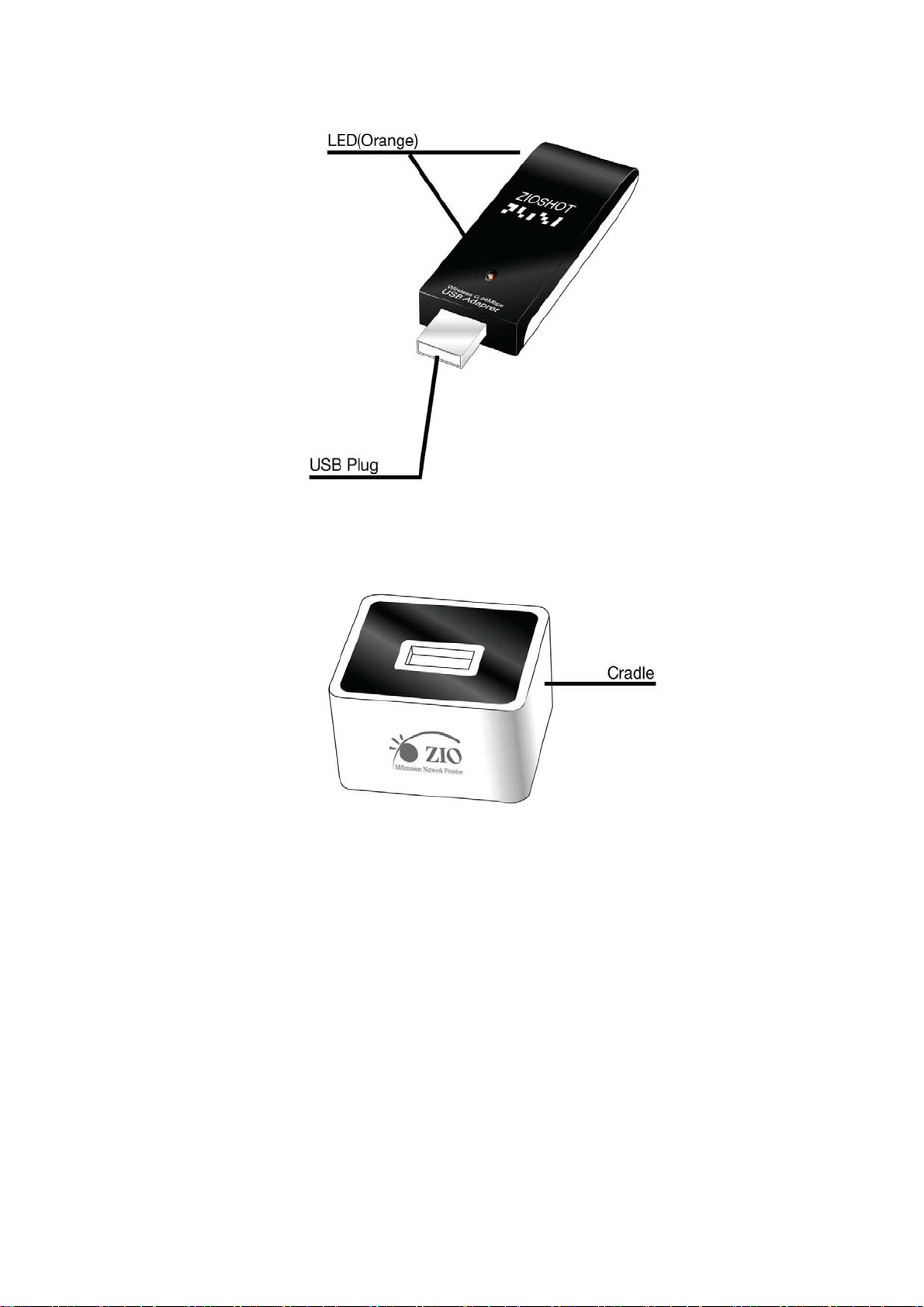
Cradle type USB 2.0 extension cable
.

1.2 Specifications
aStandards: IEEE 802.11b, IEEE 802.11g, IEEE 802.1x, IEEE 802.11b/g
aBus Type: USB 2.0 Type A
aFrequency Band: 2.4000 ~ 2.4835GHz (Industrial Scientific Medical Band)
aModulation: OFDM with BPSK, QPSK, 16QAM, 64QAM (11g) ,BPSK, QPSK, CCK (11b)
aData Rate: 54/48/36/24/18/12/11/9/6/5.5/2/1Mbps auto fallback
aSecurities: 64/128-bit WEP Data Encryption, WPA (TKIP with IEEE 802.1x), WPA2 (AES with
IEEE 802.1x) Note: WPA2 is only enabled in Windows 2000/XP/2003 Server.
a Antenna: Internal
aDrivers: Windows 98SE/Me/2000/XP/2003 Server, Linux, Mac OS X
a LEDs: Link/Activity
aTransmit Power: 10dBm
aReceive Sensitivity: -70dBm@54Mbps
aDimension: 9(H) x 26(W) x 76(D) mm
aTemperature: 32~104°F (0 ~ 40°C)
aHumidity: 10-90% (NonCondensing)
a Certification: FCC, CE

1.3 Package Contents
Before you begin the installation, please check the items of your package. The package should
include the following items:
․One USB Adaptor ․One Cradle type USB 2.0 Extension Cable․One CD (Driver/User’s Guide)
If any of the nabove items is missing, contact your supplier as soon as possible.
2 Installation Procedure
Before you proceed with the installation, please notice following descriptions.
Note1: Please do not install the adaptor into your computer before installing the software
program from the CD.
Note2: The following installation was operated under Windows XP. (Procedures are similar for Windows
98SE/Me/2000/2003 Server.)
Note3: If you have installed the Turbo Wireless LAN USB Adaptor driver & utility before, please
uninstall the old version first.
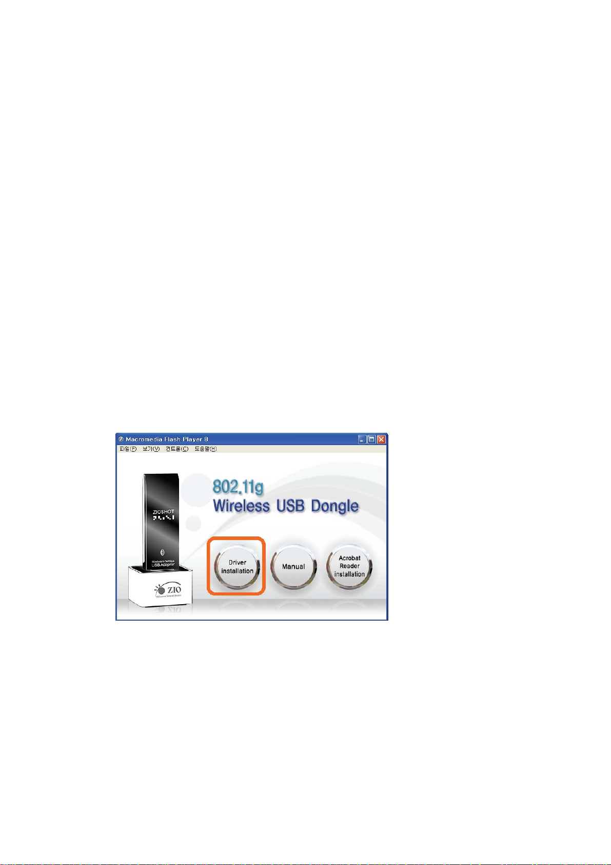
1. Insert the Installation CD to your CD-ROM Drive then you can see the User interface as right side.
1-1 Click the “Driver installation” ” to process the installation
1-2 If you want to see the User’s manual, click the “Manual”
1-3 You can not see the Manual without Acrobat Reader program, please click the “Acrobat Reader
installation”
.
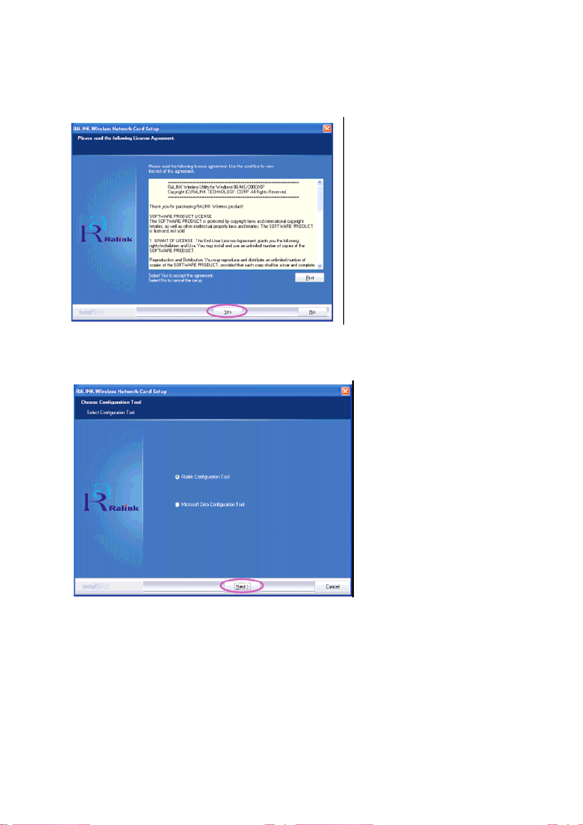
2. Click “Yes” to process the installation if you accept the license agreement.
3. In Windows XP, there is a “Windows Zero Configuration Tool” for you to setup the wireless adaptor. You can
choose to configure the adaptor through the Windows Zero Configuration Tool or the Ralink Configuration
Tool for the adaptor. It is recommended to choose the Ralink Configuration Tool for the adaptor. Click “Next”
to continue.

4. If you need the adaptor to operate with better performance, please choose the “Optimize for performance”
to enable the Tx Burst mode. Or you can choose “Optimize for Wi-Fi mode” to let the adaptor run in
standard wireless network.
5. The system starts to install the software of the adaptor. Please follow the instructions of the program to plug
in the adaptor into the USB port of your computer. And the system will automatically detect the adaptor

6. Please click “Finish” to complete the installation.
3 Configuration Utility
The Ralink Configuration Utility is a powerful application that helps you configure the USB adaptor and monitor
the link status and the statistics during the communication process.
When the adaptor is installed, the configuration utility will be displayed automatically. This adaptor will auto
connect to wireless device which has better signal strength and no wireless security setting.
The Ralink Configuration Utility appears as an icon on the system tray of Windows while the adaptor is running.
You can open the utility by double-click on the icon.

In Windows XP, there is a “Windows Zero Configuration Tool” for you to setup wireless clients. If you want to
switch to use Ralink configuration utility, please follow one of the ways as below.
First Way
Right click the icon in the system tray and select “Use RaConfig as Configuration utility”.
Second Way
A. Right-click the icon and select “View Available Wireless Networks”.
B. Click “Advanced”.

C. Uncheck “Use Windows to configure my wireless network settings” to enable the utility for the adaptor.
Note: If “Wireless Zero Configuration” is enabled, you can only configure the advance setting or check the link
status and statistics from the configuration utility of the adaptor.

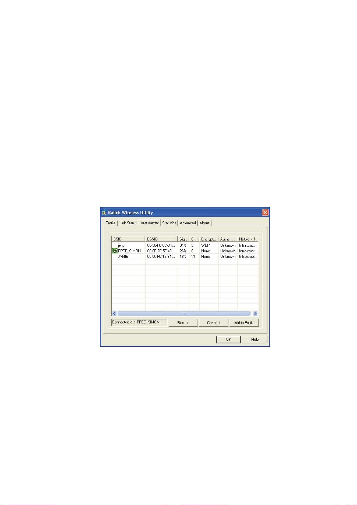
3.1 Site Survey
When you open the Ralink Configuration Utility, the system will scan all the channels to find all the access
points/stations within the accessible range of your adaptor and automatically co nnect to the wireless device with
the highest signal strength. From the “Site Survey”, all the networks nearby will be listed. You can change the
connection to another networks or add one of the networks to your own
Parameter Available
Networks
Rescan Button
Connect Button Click “Connect” to connect to the selected network.
Add to Profile Button Add the selected network to Profiles list.
Description This list shows all available wireless networks within range
of your adaptor. It also displays the information of the networks
including the SSID, BSSID, Signal Strength, Channel, Encryption,
Authentication and Network Type. If you want to connect to any
networks on the list, double-click the item on the list, and the adaptor
will automatically connect to the selected network.
Click “Rescan” button to collect the new information of all the wireless
networks nearby.

3.2 Profile
The “Profiles List” is for you to manage the networks you connect to frequently. You are able to
Add/Delete/Edit/Activate a profile.
Parameter Profiles List Description The profiles list display all the profiles and the relative
settings of the profiles including Profile Name, SSID, Channel, etc.
This sign indicates the activated profile is been connecting. This sign
indicates the activated profile is not been connecting.
Add/Delete/Edit Button Click these buttons to add/delete/edit the selected profiles.
Activate Button
Click “Activate” to connect to the selected profile. When a profile is
activated, the adaptor will be initially connected to the profile.

3.2.1 Configure the Profile
3.2.1.1 Configuration
Parameter Profile Name
Description Define a recognizable profile name for you to identify the
different networks.
SSID
The SSID (up to 32 printable ASCII characters) is the unique name
identified in a WLAN. The ID prevents the unintentional merging of
two co-located WLANs.
You may specify a SSID for the adaptor and then only the device
with the same SSID can interconnect to the adaptor. If you want to
add the network nearby to the profile list, pull down the menu, all the
networks will be listed for you to add one of them to the profile list.
Parameter Description
PSM (Power Saving Mode) The power saving function is only available when the network type is
in Infrastructure.
CAM (Constantly Awake Mode) – The adaptor will always set in
active mode.

PSM (Power Saving Mode) – Enable the adaptor in the power
saving mode when it is idle.
Network Type
Infrastructure – This operation mode requires the presence of an
802.11 Access Point. All communication is done via the Access
Point or Router.
Ad-Hoc – Select this mode if you want to connect to another wireless
stations in the Wireless LAN network without through an Access
Point or Router.
TX Power
If you want to lower the transmit power of the adaptor for saving the
power of the system, you can select the lower percentages from the
list. The lower power will cause the lower signal strength and the
coverage range.
Ad Hoc Wireless Mode
When the adaptor is set in Ad Hoc (Peer to Peer Mode), you can
designate the wireless connection mode for the Ad Hoc network.
802.11 B only – This adaptor can be compatible with both 802.11g
and 802.11b wireless stations. If there are only 802.11b wireless
stations in the network, you can set the adaptor to this mode.
802.11 B/G mix – If you have a mix of 802.11b and 802.11g wireless
stations in your network, it is recommended to set the adaptor to this
mode. This mode is also the default setting.
Preamble
802.11 G only – This adaptor can be compatible with both 802.11g
and 802.11b wireless stations. If there are only 802.11g wireless
stations in the network, you can set the adaptor to this mode.
The preamble defines the length of the CRC block for communication
among wireless devices. This option is only active in the Ad Hoc
network.
There are two modes including Auto and Long Preamble. If
“Auto“ mode is selected, the adaptor will auto switch the preamble
mode depending on the wireless devices the adaptor is connecting
to.

Parameter Description
RTS Threshold Minimum packet size required for an RTS (Request To Send). For packets
smaller than this threshold, an RTS is not sent and the packet is transmitted
directly to the wireless network. Select a setting within a range of 0 to 2347
bytes. Minor change is recommended.
Fragment Threshold The value defines the maximum size of packets; any packet size larger than
the value will be fragmented. If you have decreased this value and
experience high packet error rates, you can increase it again, but it will likely
decrease overall network performance. Select a setting within a range of
256 to 2346 bytes. Minor change is recommended.
Channel This setting is only available for Ad Hoc mode. Select the number of the
radio channel used for the networking. The channel setting should be the
same with the network you are connecting to.
3.2.1.2 Authentication and Security
Parameter Description
Authentication Type This setting has to be consistent with the wireless networks that the a daptor
intends to connect. Open – No authentication is needed among the wireless
network.
Shared – Only wireless devices using a shared key (WEP Key identified)
are allowed to connecting each other.

Parameter Description
Authentication Type LEAP – LEAP is a pre-EAP, Cisco-proprietary protocol, with many of the
features of EAP protocols. Cisco controls the ability of other vendors to
implement this protocol, so it should be selected for use only when limited
vendor choice for client, access-point, and server products is not a concern.
When you have set up LEAP authentication, you have to enter the user
name and password of your computer.
WPA – WPA provides a scheme of mutual authentication using either IEEE
802.1x/Extensible Authentication Protocol (EAP) authentication or
pre-shared key (PSK) technology. It provides a high level of assurance to
enterprises, small businesses and home users that data will remain
protected and that only authorized users may access their networks. For
enterprises that have already deployed IEEE 802.1x authentication, WPA
offers the advantage of leveraging existing authentication databases and
infrastructure.
WPA-PSK – It is a special mode designed for home and small business
users who do not have access to network authentication servers. In this
mode, known as Pre-Shared Key, the user manually enters the starting
password in their access point or gateway, as well as in each wireless
stations in the network. WPA-PSK takes over automatically from that point,
keeping unauthorized users that don't have the matching password from
joining the network, while encrypting the data traveling between authorized
devices.
WPA2 – Like WPA, WPA2 supports IEEE 802.1x/EAP authentication or
PSK technology. It also includes a new advanced encryption mechanism
using the Advanced Encryption Standard (AES). AES is required to the
corporate user or government users. The difference between WPA and
WPA2 is that WPA2 provides data encryption via the AES. In contrast, WPA
uses Temporal Key Integrity Protocol (TKIP).
WPA2-PSK – WPA2-PSK is also for home and small business. The
difference between WPA-PSK and WPA2-PSK is that WPA2-PSK
provides data encryption via the AES. In contrast, WPA-PSK uses
Temporal Key Integrity Protocol (TKIP).
802.1x Setting When you have set the Authentication Type to Open, Shared, WPA or
WPA2, you can also enable IEEE 802.1x setting to use the
authentication server or certification server to authenticate client users.

Parameter
Encryption Mode
WPA Pre-Shared Key
Description
None – Disable the encryption mode.
WEP – Enable the WEP Data Encryption. When the item is selected,
you have to continue setting the WEP Encryption keys.
TKIP – TKIP (Temporal Key Integrity Protocol) changes the temporal
key every 10,000 packets (a packet is a kind of message transmitted
over a network.) This ensures much greater security than the standard
WEP security.
AES – AES has been developed to ensure the highest degree of
security and authenticity for digital information and it is the most
advanced solution defined by IEEE 802.11i for the security in the
wireless network.
Note: All devices in the network should use the same encryption
method to ensure the communication.
The WPA-PSK key can be from 8 to 64 characters and can be letters
or numbers. This same key must be used on all of the wi reless station s
in the network.
WEP Key (Key1 ~ Key4)
The WEP keys are used to encrypt data transmitted in the wireless
network. There are two types of key length: 64-bit and 128-bit. Select
the default encryption key from Key 1 to Key 4 by selected the radio
button.
Fill the text box by following the rules below. 64-bit – Input 10-digit Hex
values (in the “A-F”, “a-f” and “0-9” range) or 5-digit ASCII characters
(including “a-z” and “0-9”) as the encryption keys. For example:
“0123456aef“ or “test1”.
128-bit – Input 26-digit Hex values (in the “A-F”, “a-f” and “0-9” range)
or 13-digit ASCII characters (including “a-z” and “0-9”) as the
encryption keys. For example: “01234567890123456789abcdef“ or
“administrator”.

The IEEE 802.1X specification describes a protocol that can be used for authenticating both clients and servers
on a network. The authentication algorithms and methods are those provided by the Extensible Authentication
Protocol (EAP), a method of authentication that has been in use for a number of years on networks that provide
Point-to-Point Protocol (PPP) support as many internet service providers and enterprises do.
When an AP acting as an authenticator detects a wireless station on the LAN, it sends an EAP-Request for the
user's identity to the device. (EAP, or the Extensible Authentication Protocol, is an authentication protocol that
runs before network layer protocols transmit data over the link.) In turn, the device responds with its identity, and
the AP relays this identity to an authentication server, which is typically an external RADIUS server.
An example for MD5 Authentication

ٛ
3.2.1.3 802.1x Setting-Certification
Parameter Description
Authentication Type The EAP authentication protocols this adaptor has supported are
included as follows. This setting has to be consistent with the wireless
APs or Routers that the adaptor intends to connect.
PEAP &TTLS – PEAP and TTLS are similar and easier than TLS in
that they specify a stand-alone authentication protocol be used within
an encrypted tunnel. TTLS supports any protocol within its tunnel,
including CHAP, MS-CHAP, MS-CHAPv2, PAP and EAP-MD5. PEAP
specifies that an EAP-compliant authentication protocol must be used;
this adaptor supports EAP-MSCHAP v2, EAP-TLS/Smart Card and
Generic Token Card. The client certificate is optional required for the
authentication.
TLS/Smart Card –TLS is the most secure of the EAP protocols but not
easy to use. It requires that digital certificates be exchanged in the
authentication phase. The server presents a certificate to the client.
After validating the server’s certificate, the client presents a client
certificate to the server for validation.
MD5-Challenge – MD5-Challenge is the easiest EAP Type. It requires
the wireless station to enter a set of user name and password as the
identity to RADIUS Server.
Session Resumption
There are “Disabled”, “Reauthentication”, “Roaming”, “SameSsid” and
“Always” selections for you to choose whether to recovery the session
in different status.
Identity Enter the name as the identity for the server.
Password Enter the password as the identity for the server.
Use Client Certificate
A client certificate is required for TLS, and is optional for TTLS and
PEAP. This forces a client certificate to be selected from the
appropriate Windows Certificate Store and made available to the
RADIUS server for certification.
Parameter
Tunneled Authentication
Description
Protocol When the authentication type is PEAP or TTLS, select a protocol to
be used to build the encrypted tunnel.

Identity
This is the protected user EAP Identity used for authentication. The
identity specified may contain up to 63 ASCII characters, is case
sensitive and takes the form of a Network Access Identifier,
consisting of <name of the user>@<user’s home realm>. The user’s
home realm is optional and indicates the routing domain.
Password
The password used for authentication. It may contain up to 63 ASCII
characters and is case sensitive.
3.2.1.4 802.1x Setting-CA Server
Parameter Description
Use Certificate Chain When the EAP authentication type such as TLS, TTLS or PEAP is
selected and required a certification to tell the client what server
credentials to accept from the authentication server in order to verify
the server, you have to enable this function.
Certificate Issuer
Choose the server from the list to issue the certificate. If “Any Trusted
CA” is selected, any CA included in the list (provided by the Microsoft
Certificate Store) is permitted.
Parameter
Allow Intermediate Certificates
Description
A server designates an issuer as a trusted root authority by
placing the issuer's self-signed certificate, which contains the
issuer's public key, into the trusted root certification authority
certificate store of the host computer. Intermediate or
subordinate certification authorities are trusted only if they have
a valid certification path from a trusted root certification authority.
Server Name Enter the authentication server name.

Server name must match
exactly
Domain name must end in
specified name
When selected, the server name must match exactly the server
name found on the certificate.
When selected, the server name field identifies a domain. The
certificate must use a server name belonging to this domain or to
one of its sub-domains (e.g. zeelans.com, where the server is
blueberry.zeelans.com) but it may be any name used in the
certificate name field.
3.3 Link Status
From the “Link Status” option, you can view all the information of the network you are connecting to.
Parameter
Status
Extra Info Display the link status.
Channel
Link Speed (Mbps)
Throughput (Kbps) Display the speed of data transmitted and received.
Link Quality
Description
Display the SSID and MAC ID of the network the adaptor is connecting
to.
Display the number of the radio channel and the frequency used for
the networking.
Display the transmission and reception rate of the network. The
maximum transmission rate is 54Mbps.
This bar indicates the quality of the link. The higher the percentage,
the better the quality.

dBm
If you want to know the signal strength in the unit of dBm, select this
check box.
Signal Strength
This bar shows the signal strength level. The higher percentage
shown in the bar, the more radio signal been received by the adaptor.
This indicator helps to find the proper position of the wireless device
for quality network operation.
Noise Level Display the noise level in the wireless environment.
3.4 Statistics
This option enables you to view the statistic information of the connection including transmit statistics and
receive statistics. You may reset the counters by clicking ”Reset Counter”.
3.5 Advance
This option enables you to configure more advanced settings, for example: wireless mode, protection mode and
etc.

Parameter Description
Wireless Mode 802.11 B/G mix – If you have a mix of 802.11b and 802.11g wireless
stations in your network, it is recommended to set the adaptor to this
mode. This mode is also the default setting.
802.11 B only – This adaptor can be compatible with both 802.11g and
802.11b wireless stations. If there are only 802.11b wireless stations in the
network, you can set the adaptor to this mode.
802.11 G only – This adaptor can be compatible with both 802.11g and
802.11b wireless stations. If there are only 802.11g wireless stations in the
network, you can set the adaptor to this mode.
B/G Protection If you have a mix of 802.11b and 802.11g wireless stations in the network, it
is recommended to enable the protection mechanism. This mechanism can
decrease the rate of data collision between 802.11b and 802.11g wireless
stations. When the protection mode is enabled, the throughput of the
adaptor will be a little lower due to many of frame traffic should be
transmitted. Auto – Based on the status of the network and automatically
disable/enable protection mode.
On – Always enable the protection mode.
Off – Always disable the protection mode.
Tx Rate There are several options including
Auto/1/2/5.5/11/6/9/12/18/24/36/48/54Mbps for you to select. When the
“Auto” is selected, the device will choose the most suitable transmission rate

automatically. The higher data rate you designated in the network, the
shorter distance is allowed between the adaptor and the wireless stations.
When the wireless mode is “802.11 B only”, the maximum data rate is
11Mbps (11b) so that there are only “Auto/1/2/5.5/11Mbps” options you can
select.
Tx BURST Tx Burst enables the adaptor to deliver better throughput in the same
period and environment.
Parameter Description
Enable TCP Window Size The TCP Window is the amount of data a sender can send on a
particular connection before it gets an acknowledgment back from
the receiver that it has gotten some of it. When the Router or AP
the adaptor is connecting to have set up the TCP Window, you can
enable the parameter to meet the data size for the Router or AP
connection. The larger TCP Window the better performance.
Fast Roaming at -70dBm When you want to fast roaming to the network nearby without
intercepting the wireless connection especially the adaptor is
applied to the multimedia application or a voice call, you can
enable the parameter. The adaptor will fast roaming to the near
network when the receive sensitivity (signal strength) is lower to
the value you have set up.
Turn Off RF Button
If you want to turn off the radio of the adaptor temporarily, click this
button. To turn on the radio, click this button again.
CCX 2.0
CCX 2.0 (Cisco Compatible Extensions) is developed by Cisco for
the radio monitoring and fast roaming.
LEAP Turn on CCKM
During normal operation, LEAP-enabled client devices mutually
authenticate with a new access point by performing a complete
LEAP authentication, including communication with the main
RADIUS server.
When you configure your wireless LAN for fast re-association,
however, LEAP-enabled client devices roam from one access
point to another without involving the main server. Using Cisco
Centralized Key Management (CCKM), an access point configured
to provide Wireless Domain Services (WDS) takes the pla ce of the
RADIUS server and authenticates the client so quickl y that there is
no perceptible delay in voice or other time-sensitive applications.
Enable Radio Measurement
When this parameter is enabled, the Cisco AP can run the radio
monitoring through the associated CCX-compliant clients to
continuously monitor the WLAN radio environment and discover
any new APs that are transmitting beacons.
Non-Serving Channel
Measurements
The Cisco AP can perform monitoring measurements through the
CCX-compliant clients on the non-serving channels when this
parameter is enabled.
Limit xxx milliseconds (0-2000)
It limits the channel measurement time. The default value is 250
milliseconds.
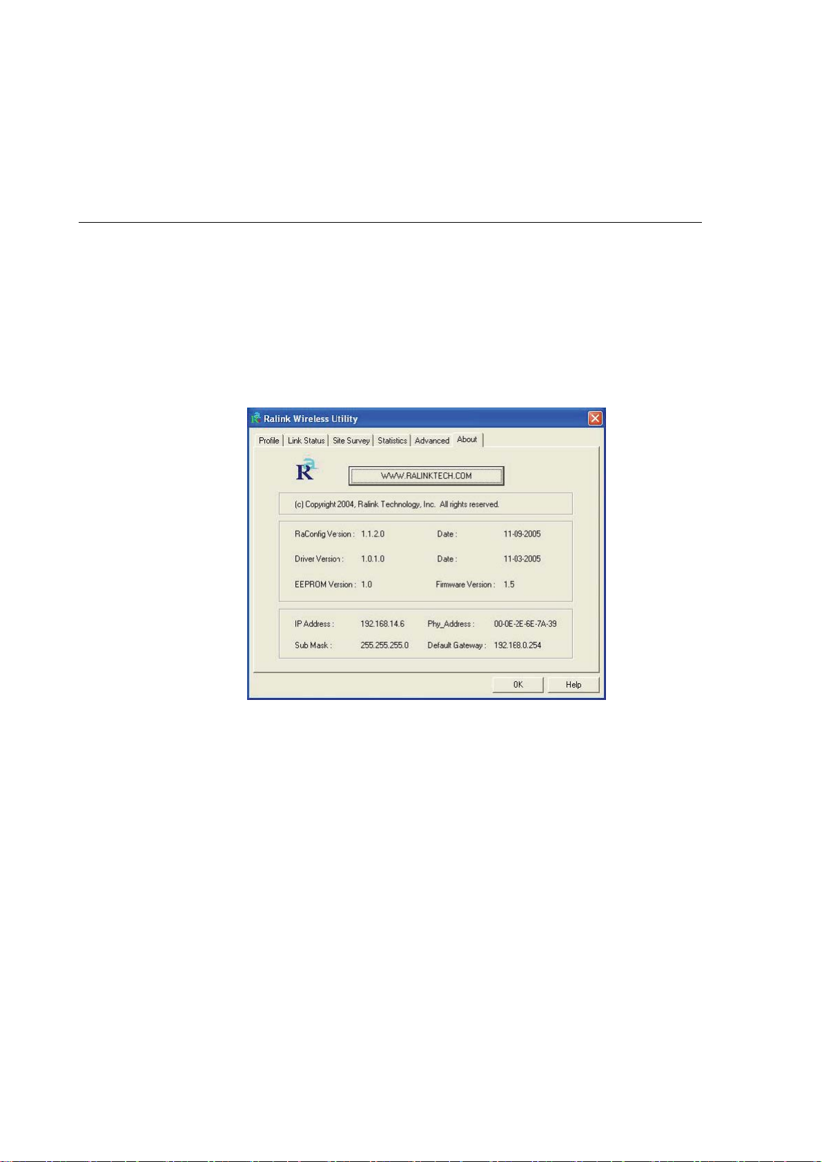
3.6 About
By choosing this option, you can click the hyperlink to connect the website for the information of the wireless
chipset vendor and review basic information about the Utility such as the Driver, Utility and EEPROM Version.
The MAC Address of the adaptor is displayed in the screen as well.

3.7 Turbo Mode
This adaptor supports specific ways to increase the data transfer rate at a time; compress the data and
decrease the waiting time to send the next data to the Routers or APs, this feature (known as Turbo Mode)
enables higher throughput than IEEE 802.11g standard (Up to 54Mbps).
When the adaptor is connecting to the Routers or APs with the proprietary Turbo Mode feature, the Turbo
Mode will be enabled automatically without any configuration.

4 Troubleshooting
This chapter provides solutions to problems usually encountered during the installation and operation of the
adapter.
1. What is the IEEE 802.11g standard?
802.11g is the new IEEE standard for high-speed wireless LAN communications that provides for up to 54
Mbps data rate in the 2.4 GHz band. 802.11g is quickly becoming the next mainstream wireless LAN
technology for the home, office and public networks. 802.11g defines the use of the same OFDM
modulation technique specified in IEEE 802.11a for the 5 GHz frequency band and applies it in the same
2.4 GHz frequency band as IEEE 802.11b. The 802.11g standard requires backward compatibility with
802.11b.
The standard specifically calls for:
A. A new physical layer for the 802.11 Medium Access Control (MAC) in the 2.4 GHz frequency band,
known as the extended rate PHY (ERP). The ERP adds OFDM as a mandatory new coding scheme
for 6, 12 and 24 Mbps (mandatory speeds), and 18, 36, 48 and 54 Mbps (optional speeds). The ERP
includes the modulation schemes found in 802.11b including CCK for 11 and 5.5 Mbps and Barker
code modulation for 2 and 1 Mbps.
B. A protection mechanism called RTS/CTS that governs how 802.11g devices and 802.11b devices
interoperate.
2. What is the IEEE 802.11b standard?
The IEEE 802.11b Wireless LAN standard subcommittee, which formulates the standard for the industry.
The objective is to enable wireless LAN hardware from different manufactures to communicate.
3. What does IEEE 802.11 feature support?
The product supports the following IEEE 802.11 functions:
aCSMA/CA plus Acknowledge Protocol aMulti-Channel Roaming aAutomatic Rate Selection aRTS/CTS
Feature
aFragmentation aPower Management
4. What is Ad-hoc?
An Ad-hoc integrated wireless LAN is a group of computers, each has a Wireless LAN adapter,
Connected as an independent wireless LAN. Ad hoc wireless LAN is applicable at a departmental scale
for a branch or SOHO operation.
5. What is Infrastructure?
An integrated wireless and wireless and wired LAN is called an Infrastructure configuration.
Infrastructure is applicable to enterprise scale for wireless access to central database, or wireless
application for mobile workers.

6. What is BSS ID? A specific Ad hoc LAN is called a Basic Service Set (BSS). Computers in a BSS must be
configured with the same BSS ID.
7. What is WEP? WEP is Wired Equivalent Privacy, a data privacy mechanism based on a 40 bit shared key
algorithm, as described in the IEEE 802 .11 standard.
8. What is TKIP? TKIP is a quick-fix method to quickly overcome the inherent weaknesses in WEP security,
especially the reuse of encryption keys. TKIP is involved in the IEEE 802.11i WLAN security standard,
and the specification might be officially released by early 2003.
9. What is AES? AES (Advanced Encryption Standard), a chip-based security, has been developed to ensure
the highest degree of security and authenticity for digital information, wherever and however
communicated or stored, while making more efficient use of hardware and/or software than previous
encryption standards. It is also included in IEEE 802.11i standard. Compare with AES, TKIP is a
temporary protocol for replacing WEP security until manufacturers implement AES at the hardware level.
10. Can Wireless products support printer sharing? Wireless products perform the same function as LAN
products. Therefore, Wireless products can work with Netware, Windows 2000, or other LAN operating
systems to support printer or file sharing.
11. Would the information be intercepted while transmitting on air? WLAN features two-fold protection in
security. On the hardware side, as with Direct Sequence Spread Spectrum technology, it has the inherent
security feature of scrambling. On the software side, WLAN series offer the encryption function (WEP) to
enhance security and Access Control. Users can set it up depending upon their needs.
12. What is DSSS?What is FHSS?And what are their differences? Frequency-hopping spread-spectrum
(FHSS) uses a narrowband carrier that changes frequency in a pattern that is known to both transmitter
and receiver. Properly synchronized, the net effect is to maintain a single logical channel. To an
unintended receiver, FHSS appears to be short-duration impulse noise. Direct-sequence
spread-spectrum (DSSS) generates a redundant bit pattern for each bit to be transmitted. This bit pattern
is called a chip (or chipping code). The longer the chip is, the greater the probability that the original data
can be recovered. Even if one or more bits in the chip are damaged during transmission, statistical
techniques embedded in the radio can recover the original data without-the need for retransmission. To
an unintended receiver, DSSS appears as low power wideband noise and is rejected (ignored) by most
narrowband receivers.
13. What is Spread Spectrum? Spread Spectrum technology is a wideband radio frequency technique
developed by the military for use in reliable, secure, mission-critical communication systems. It is designed to
trade off bandwidth efficiency for reliability, integrity, and security. In other words, more bandwidth is consumed
than in the case of narrowband transmission, but the trade off produces a signal that is, in effect, louder and thus
easier to detect, provided that the receiver knows the parameters of the spread-spectrum signal being
broadcast. If a receiver is not tuned to the right frequency, a spread –spectrum signal looks like background
noise. There are two main alternatives, Direct Sequence Spread Spectrum (DSSS) and Frequency Hopping
Spread Spectrum (FHSS).
 Loading...