


1
SD-Models
SD MODEL, INC.
Warehouse
United States A
d-
dress
252 Michelle Court
South San Francisco, CA
94080 USA
Warehouse :
650-886-3028
Office :
415-933-8313
Fax :
415-933-6003
35% Extra 260 Assembly Manual
For assistance contact :
Copyright © 2006 by SD-Models, Inc., Inc. All rights reserved.
First edition rev. 7.06.19
please report errors to sales@toc1.com

2
Warranty Information:
SD-Models, Inc. guarantees this kit to be free of defects in both material and wor
manship at the time of purchase. This warranty does not cover any components da
aged by use or modification. In no case shall SD-Models, Inc., Inc. liability exceed the
original cost of the purchased kit.
Further, SD-Models, Inc. reserves the right to change or m
notice. In that SD-Models, Inc. has no control over final assembly or materials used
in final assembly, no liability shall be assumed or accepted for any damage resulting
from the use by user of the final user assembled product
assembled product, the user accepts all resulting liability. The user should check the
aircraft for structural damage before each flying session and immediately after any
ground strike other than a soft landing. DO NOT ATT
CRAFT WITH ANY STRUCTURAL DAMAGE!
If the buyer is not prepared to accept the liability associated with the use of this pro
uct, the buyer is advised to return this kit immediately in new and unused con
the place of purchase.
While this kit has been flight tested to exceed normal use, if the plane will be used for
extremely high stress flying such as racing or extreme aerobatics the modeler is r
sponsible for taking steps to reinforce the high stress points. If you do not feel c
dent to do this, seek advice from experienced modelers.
T
his model
Academy of Model Aeronautics National Model Aircraft Safety Codes.
should never be operated
in a manner that is not compliant with all of the
odify this warranty without
. By the act of using the user
EMPT TO FLY AN AI
dition to
onf
k-
m-
R-
d-
e-
i-
Read through this manual before startin
tion. It contains important warnings and instructions
concerning the assembly and use of this model.
The pictures in this manual may be of airplanes with different covering schemes.
The planes pictured were of identical construction. Only the
different.
g constru
c-
color schemes were

3
Warning. This is not a toy. If not properly con
Specifications
Model Name Extra 260 35%
Wingspan
102 in.
Wing Area 1872 sq.in.
Fuselage Length 88 in.
Engine Size 100cc Class
Flying Weight 27.5 lbs.
trolled it
can cause injury or death and prop
Included Hardware: Aluminum spinner, fuel tank, aircraft grade aluminum
wing-tube, aluminum main gear, rubber wheels, t
num servo arms, aluminum stab tube for removable stab, control horns,
hinges, wheel pants, SAE bolts and nuts, much more.
erty damage.
ail wheel bracket, alum
i-
CANISTER READY, COWL RING MOUNT, PRE-HINGE-SLOTTED SU
FACES, PUSH-RODS AND CONTROL LINKAGES INCLUDED, POLISHED
SPINNER INCLUDED FUEL TANK, WHEELS, LANDING GEAR, MOUNTING
HARWARE, NUTS, BOLTS AND MORE –
FULL PARTS SUPPORT IN STOCK
Flexing in linkage can and will cause flutter of the control surfaces which will
destroy the airplane in just a few seconds. Metal gear servos are required.
ALL INCLUDED
R-

4
Table of Contents
Page
Subject
5 Open and inspec
t everything
6 Mount the engine
8 Hinge the control surfaces
9 Mount the hatch and canopy
11 Install the control horns
12 Install the elevator servos
13 Mount the horizontal stabilizers
13 Aileron Servo Installation
14 Throttle and (optional) choke servo installation.
14 Install the landing gear
16 Mount the rudder servo and linkage
16 Install a fuel tank and fuel system
17 Prepare and Mount Cowl
18 Mount the wings
18 Final Checks
19 Check and adjust balance
19 Control throws

5
35% Extra 260 Assembly Ma
nual
Step 1. Open and inspect everything
This section should be fairly self explanatory.
In the large box you should have a fuselage with hatch., wing tube and dual stab
tubes, the elevator/stab assemblies, the rudder, cowl, wheel pants, canopy, and a
pa
ckage with the landing gear, tail wheel bracket and miscellaneous nuts and bolts.
Use some acetone on a rag to clean the glue off the tubes. Under all of this is a
false floor, and under that you will find the wings with ailerons attached. The
hinges are i
have to do that.
good luck with Pro-bond Ultimate and Gorilla glue, both of which are glues that
expand as they dry cure and fill the voids in the hinges and their sockets.
Check everything for shipping damage and/or manufacturing defects.
problem, report it to us NOW
Read the quick start guide at the end of this manual
and any errata corrections that may be available.
Before proceeding to any assembly, now is a good time to go over the whole plane
and fix any cosmetic flaws. Some cosmetic flaws are to be expected, this fact is r
flected in t
nstalled in the elevators and ailerons
The hinges for the rudder are in the hardware pack. We have had
, not after you start building the plane.
he price.
, but they are not glued, you
If there is a
first. It has helpful hints
e-
Using This Manual
When you start a construction section, it is a good idea to first read that entire se
tion before cutting or drilling or glueing. For example, if you are about to begin
the section called “Mount the Hatch and Canopy”, then read that entire section b
fore doing anything else. Toward the end of that section, there is an option to paint
frame line on the inside of the canopy. If you’ve already glued it on, it will be impossible. Reading the entire section will give you a good
headed and any options available.
c-
e-
feel of where you are

6
Known issues and improvements
There are a few areas where, at this unassembled stage, you can improve the final
results of your assembly project. There are many items that cannot be addressed on
the assembly line due to cost and possibly because not every improvement would
be welcomed by every builder. Here are a few items that have come up over time.
Go over the covering with a heat gun or iron
. The covering tends to get loose
over time and with changes in temperature and humidity. It may have come out of
the box with wrinkles, I can assure you it did not go into the box that way.
Clean out the hinge holes.
Without removing any wood, use a very sharp X-acto
knife and remove any covering that may have been pushed into the hinge holes. It
is very important that the glue sticks to the wood and not to the covering.
Lightweight landing gear and wing tube.
to provide as much flexibility as possible with regard to engine
In the 35% EXTRA 260 we have tried
choice. It is som
etimes difficult to be all things to all people. In any case, we have provided very
strong landing gear and wing tubes, which are suitable for any type of engine and
flying but add some weight to the finished plane. Some pilots chose to
bon fiber landing gear and/or wing tubes. This can save several ounces of weight.
Hardening holes.
The fuselage sides on this plane are made of balsa which in ce
order ca
r-
rtain areas is doubled by lite-ply. Using wood screws in balsa is difficult because
balsa is very soft. It’s a good idea whenever you drill a hole that must accept a
wood screw to put a drop of thin CA into the hole and then if necessary re-drill the
hole. The CA will wick into the wood and harden it, adding strength in that area.
Engi
ne mounting
PLEASE READ THE INSTRUCTIONS FOR STEP 2 COMPLETELY BEFORE
CUTTING ANYTHING!
The first thing to do, before anything else goes in the fuselage, is to get the engine
mounted and aligned with the cowl. This can be a little tricky, so take your tim
e.
This is perhaps the most difficult part of building this kit, so once you get this
right, you’re on your way to having a great plane. Do this first before you hinge
the rudder.
Note that the firewall already has a proper amount of right thrust built i
n, do not
use any other offsets. When you shim the engine out from the firewall use shims of
equal thickness on all 4 corners so that you do not introduce any other thrust a
gles. The firewall is left un-glued for a reason. If you need to, you can recess
slightly to adjust for the proper engine position. Be sure to leave ¼” clearance b
tween the rear of the spinner plate and the front of the engine cowl.
n-
it
e-

7
When aligning your engine, move it ¼”-3/8” off center to the port side in order to
move the spin
ner back to the center of the cowl. The right thrust will cause it to be
off center, but this will re-center it. Take care if you are working with the plane in
an inverted position not to get mixed up.
The line that runs horizontally can be moved to accommodate your particular e
gine. However, the centerline of the crankshaft should be placed as close as poss
ble to the wing center-line extended. We are now ready to mark and drill our fir
n-
i-
ewall for our engine. It is helpful to cut an engine mount pattern out of poster board
and place it over the firewall so that the center marks of the engine pattern line up
with the new centering mark on the firewall. Use an ice pick or an awl to push
though the center of each of the 4 engine mounting holes. Make sure you make the
hole big enough to find later. When done, drill the firewall through each awl mark
with the appropriate size bit for your engine mounting bolts. (1/4 – 20) hardened,
socket head bolts and blind nuts will do nicely)
We are no
w ready to epoxy the firewall into the engine box. BE SURE TO PUT
THE TOP AT THE TOP AND THE FRONT TO THE FRONT – as labeled in the
previous step. Wipe away excess epoxy. A large blob in the wrong place will pr
event the proper fit of the triangular stock in the next step. After your wipe away
the excess, a little rubbing alcohol on a paper towel
will finish the job nicely.
After you glue the firewall to the engine box sides, r
einforce it with 1/2” triangle stock on the inside of the
firewall-above and
below mid-plate. If you want it to
be super strong, bolt 2 small pieces of aluminum angle
to the front (see diagram).

8
Hinging
Like I said, the rest is very easy.
Hinging is a very simple matter. We recommend that you hinge all the control su
faces in two steps allowing the glue to dry between steps.
Before you start gluing anything, test fit each control surface. Aileron to wing, el
r-
evator to stabilizer, rudder to fin/fuse, with the hinges in place. Make sure the
hinges go in the holes smoo
thly and that there is ample room for the hinge
“knuckle” so there is no large gap between surfaces. The hinge lines are beveled.
The point of the bevel should be at the center of the hinge pin, this assures that the
hinges are aligned and centered on the
hinge line.
Once you are certain that they all go together smoothly, take one surface and r
emove the hinges. If you have a needle oiler, place 1 or 2 drops of oil into the hinge
and work it back and forth. It’s also a good idea to put some li
on a rag, and to wipe the edges of the hinging surfaces with this rag. The oily res
te oil (like WD40)
idue will keep spilled glue from sticking to the ultracote covering. Then wipe off
any excess oil from the surface. Glue the hinges into the holes secur
ely using the

9
glue you prefer. I have had good success with Pro-bond polyurethane (not the pro
bond yellow furniture glue) because when drying it foams up slightly and fills the
gaps between the hinge and the mounting hole. Pacer Hinge glue works great f
the same reason.
Make sure the bent hinge is able to go perpendicular to the edge (see picture).
or
When the glue is dry, do the same thing with the
surface, glue the hinge legs into the holes provided. Keep the surfaces as close t
mating
ogether as possible to minimize gaps. When completed it’s a good idea to seal the
hinge gaps by ironing a piece of Ultracoat covering material into the groove b
tween the surfaces.
e-
Repeat this on both elevators and both ailerons. For the rudder you may wish to
wai
t until later to do the final installation of the rudder, it makes it easier to handle
the airplane.
To make the rudder removable, it is possible to remove the hinge pin from each
hinge (grind off the recessed end and push the pivot out) and one or two pi
ece of
wire as the pivot on all the hinges. Use the largest wire that will fit through the
hinge holes. Then to remove the rudder you just remove the wire, but be sure the
wire can’t fall out in flight. I have used a very small wheel collar to retain the
h
inge wire.
Mounting the Hatch & Canopy
The hatch mounts to the fuselage by two
tabs on each side that are attached at
the rear of the hatch. They are already
built into the hatch and should have 6-32
blind nuts mounted in them. Set the
hatch in place
6-32 bolts (supplied) thread easily into
the blind nuts. You may have slightly
enlarge the holes in the fuse if the blind
nuts don’t line up perfectly. Check also
and check to see that the

10
to see if the 2 dowels are protruding out of the front at least ¼
Mount the provided control horns to each
control surface on the hard points. Try and
get the control horn base as close to the
leading edge of the control surface. Th
is will
provide the proper geometry and allow the
control surface to move both directions
equally. For the elevators, place each horn
1” from the fuse, and the exact same di
stance from the hinge line. Otherwise, the
geometry will be different and it will
be diff
icult to adjust the throw amount to be equal
in both directions. (See diagrams below)
are glued in securely. Once you are satisfied, remove the hatch. We will now
attach the canopy to the hatch. If there is an air gap between the mounting tab
and the inside of the fuselage side, you may want to fill it with a piece of s
plywood. We have had a few incidences of flyers over-tightening the mounting
bolts until they broke or weakened the glue joint on the mounting tabs. This r
sulted in the hatch flying off in flight – leaving the mounting tabs still bolted in
place.
” – and that they
crap
e-
With a Covering Iron, touch-up any wrinkles in the Ultra-Cote covering where
your canopy will sit. Make sure the Ultra-Cote is stuck well to the balsa in this
area. Once the canopy is glued, you will not be able to get into this area. Carefully
trim the
canopy to fit the hatch. Leave a small lip in the front, it makes the attac
hment more secure. Trial fit it several times until you are happy with it. Remember, you can always trim more off but it’s hard to put back on. Attach the ca
with whatever is your favorite method. Some people use tape, some glue the ca
nopy
nopy down, some use small screws. This is up to you. If you use small screws add
some hard wood such as 1/16” ply to back up the balsa wood of the hatch. I like
E-
6000 clear glue found at your
local hobby store. If you use it, run a small
bead(1/8” diameter) all the way around the canopy. Holding the canopy by the
edges, open it slightly and carefully lower it into place. Use a few pieces of ele
trical tape to hold it in place overnight. Don
’t worry about any E-6000 that may
c-
squeeze out. It is actually easier to clean after it hardens. You can trim it carefully
with a sharp X-acto and roll it off.
Install the Control Horns

11
Find the servo bay inside of each
elevator. Fish the servo wire down
the middle and back out of the front
hole.
Stab Elevator
Mount the servo inside.
Elevator Servo Installation
12
Find the aileron servo bays in each
wing
. Cut back the covering. There
is a string attached inside . Pull it
loose and use it to pull the servo
wire through the channel in the
wing. Once again, add a servo
wire extension if necessary and
secure. Install the servo onto the
pre-installed hard w
ood rails.
Mount the aileron control horn pe
rpendicular to the servo arm in the
pre-installed hardwood mounting
base.
Mount the servo arm (supplied)
and connect the ball link and pus
h-
rod to the control
horn.
Repeat the same process on the
other elevator.
Install horizontal stabilizer
and slide the s
tabilizers onto the tubes from each side. Make sure that both stabs
are snug against fuse. Using the 6-32 allen bolts(supplied), attach the stabs to the
fuse.
Aileron Servo Installation
Use a sharp hobby knife
to carefully trim the
covering around the
holes in the fuse for the
stab tube and the bolt
holes on each side. Slide
the aluminum tube su
p-
plied) through the fuse,

13
Mount the throttle servo in the
floor of the engine box. If you
wish to use a servo to contr
ol
your choke, you can mount it
similarly. Use 2 pieces of 1/16”
ply as doublers for the screws to
have some meat on both se
r-
vos.
Using the four 8-32 X 1” long
bolts provided, and four 8
-32
locknuts provided. Mount the
landing gear to the main gear
plate as shown in th
e picture.
Temporarily mount the axle,
wheel, and wheel-pant. Make
sure not to mount it to low to the
ground – p
articularly if you fly at
a grass field.
Drill through existing holes with
1/8” bit to prepare for blind-nuts.
Main Landing Gear Installation
14
Mark and drill holes if nece
s-
sary to mount your Tailwheel.
Put a few drops of thin CA
into the holes to harden the
wood. Let it dry
.
Mount the Tailwheel.
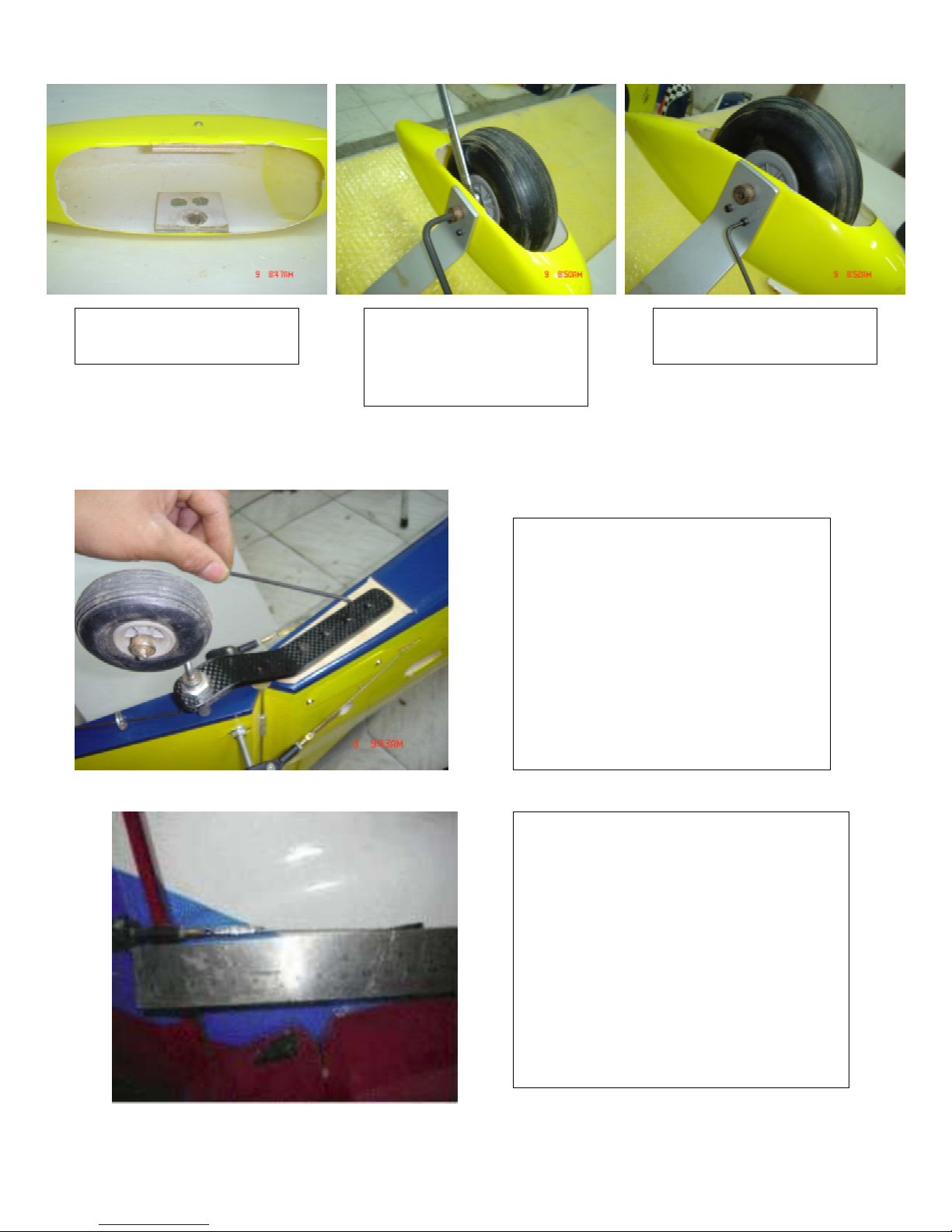
Mount the rudder control horn to the
rudder the same way as th
e elevators
and ailerons. Make sure that with full
up elevator you have plenty of clea
rance between the control horn and
the elevator. If you do not have the
proper clearance the elevator will hit
your pull-pull wire. Once your control
horn is mounted you
can now install
the pull-pull wire. Make sure that the
wire goes straight to the rudder servo
in the fuse.
Install blind-nuts.
Re-mount axle,
wheel, and wheel
-
pant.
Install 4-40 bolts.
Tail Wheel Installation
Rudder Control Horn Setup

15
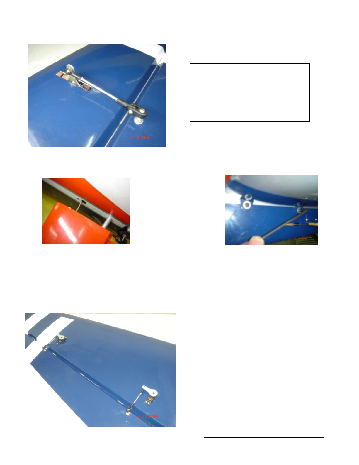
Mount the rudder servo(s).
Run the pull-pull wires down the
fuselage, and make sure the c
a-
bles are not rubbing on anything.
Attach the la
rge aluminum servo
arm securely to an existing servo
wheel and attach cables with
hardware provided. It is OK to
cross the cables to prevent ru
bbing. You may have to reverse
the servo direction in your
transmitter.
The installation of the tank (su
pplied) and fuel lines is very
straightforward.
Place a piece of foam under the
tank to prevent fuel foaming and
strap it with tie-wraps or Velcro.
Sliding it back against the wing
tube puts it clo
se to the CG and
causes the CG to remain static
throughout the flight.

16
Engine cooling and clearance
Cut out the cowl in the required spot
s
so you have plenty of clearance
around the muffler/canisters.
Provide at least this much opening. If
you do not provide enough exit for the
air, the engine will overheat.
Once the cowl is ready to mount,
slide it onto the fuselage and attach
usin
g 6-32 bolts and washers pr
ovided. Two screws go through the
firewall into the cowl ring –
Finish with the screws provided.

17
Wing Mountin
Use the supplied nylon mounting bolts
to attach the wing onto the fuselage.
Make sure that the wing bolts are in
plac
e and snug before each flight to
prevent the wing from coming off du
r-
ing flight.
7.50”
Make sure the plane balances at
7.50”. You will probably find
this to be a bit nose heavy, but it
should be safe. If the plane were
to take off tail heavy, it
may be
uncontrolla
ble. After 2 or 3 trim
flights, you can move the CG
back 1/8 ” at a time. It flies much
better once the CG is just right.
You can also log on to one of the
popular RC bulletin boards.
There you can find where other
pilots have put the
CG on their
Extra 260.
g
Final Checks
Take a few minutes to re-check each servo to make sure all screws are in place and snug.
If you use metal gear servos(a good idea), place one drop of thread locker on the screws
that hold the arms on the servos. Re-check all control
looseness. This would greatly increase the chance of flutter and could destroy your ai
plane. This is a 3D/Aerobatic airplane with large surfaces. Be careful to keep everything
tight and control your speed when flying
Put on your prop and spinner. Put in all radio and batteries. Mount all switches & attach
all wiring. Assemble the airplane, we will now check the CG.
.
horns, and all linkage for slop or
r-

18
Control Throws
Here are some starting points for the control throws.
un
til you are thoroughly familiar with the plane on low rates. The 3D rates if
pulled hard at moderately high speed will cause the plane to stall, tumble, and
hunt for dirt.
Ailerons
Elevators
Rudder
High rate(3D)
30+ deg
40+ deg.
45 deg.
Do no
t use the 3d settings
Low rate
18 deg
18 deg.
25 deg
.
Fly the plane on low rates at first. The 3d rates are intended
only for extreme aerobatics. If you are in doubt about your
skills, ask a skilled aerobatic pilot to help you with a traine
cord.
r
Thanks for Purchasing our 35% Extra 260. We hope it provides you with many
hours of enjoyment. Good luck!
Lee
 Loading...