

Page 1
801 Avenida Acaso, Camarillo, Ca. 93012 • (805) 494-0622 •
www.sdcsecurity.com • E-mail: [email protected]
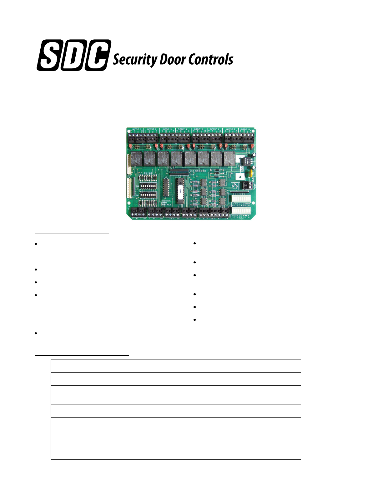
INSTALLATION INSTRUCTIONS
MODEL UR4-8
UNIVERSAL DOOR CONTROLLER
I. Features & Benefits
Microprocessor based relay controller that provides 7
different, field selectable application modes for two, three or
four door stations
3 field selectable Interlock (airlock) modes
Field selectable Communicating (shared) bathroom mode
Field selectable relay modes include:
- Conventional Relay (CR)
- Latching Relay (LR) – Pulse on, pulse off
- Time Delay Relay (TD) – 1-65 seconds
- Dual Function Relay (CR/LR, TD/LR, TD/CR, CR/CR)
Each output relay is field selectable as a dry contact or a
voltage output
II. Technical Specifications
Input Voltage: 12 or 24VDC +/- 10%
Input Current: 250/130 mA max. @ 12/24 VDC
Relay Inputs: 8-SPST, Dry, Optically Isolated
All Normally Open or Normally Closed (field selectable)
Auxiliary Inputs: 4-SPST, Dry, Normally Open, Optically Isolated
Relay Outputs: 4 fused SPDT relays, 7A @ 30VDC
4 non-fused SPDT relays, 7A @ 30VDC
Individually configurable as a dry contact or voltage output (field selectable)
Centralized wiring for all locks, access controls, monitoring
contacts, and peripheral equipment
Onboard input/output status lights for easy troubleshooting
3 system control inputs: Lock All, Unlock All, System
Lockout
Emergency release input for fire panel interface
Removable terminal blocks simplify installation
1 or 2 controllers may be installed in SDC 600 series power
supplies
Dimensions: 7" W x 5" H x 2" D
(177.8 x 127 x 50.8 mm)
P:\INSTALLATION INST\Power Supplies\INST-UR\INST-UR4-8.vsd REV A1 11-14 Page 1
Page 2
III. UR4-8 Board Layout
1
NON
C
1 2 3 4 5 6
1 2 3 4 5 6
NON
C
C
FUSE
C
FUSE
OUTPUT 2
(
N
-
)
O
7 8
7 8
Monitoring
Relay
Output
OUTPUT 2
(
-
N
)
O
N
C
C
W
W
D
D
N
C
C
W
D
OUTPUT 1 OUTPUT 3
(
-
)
W
2
6
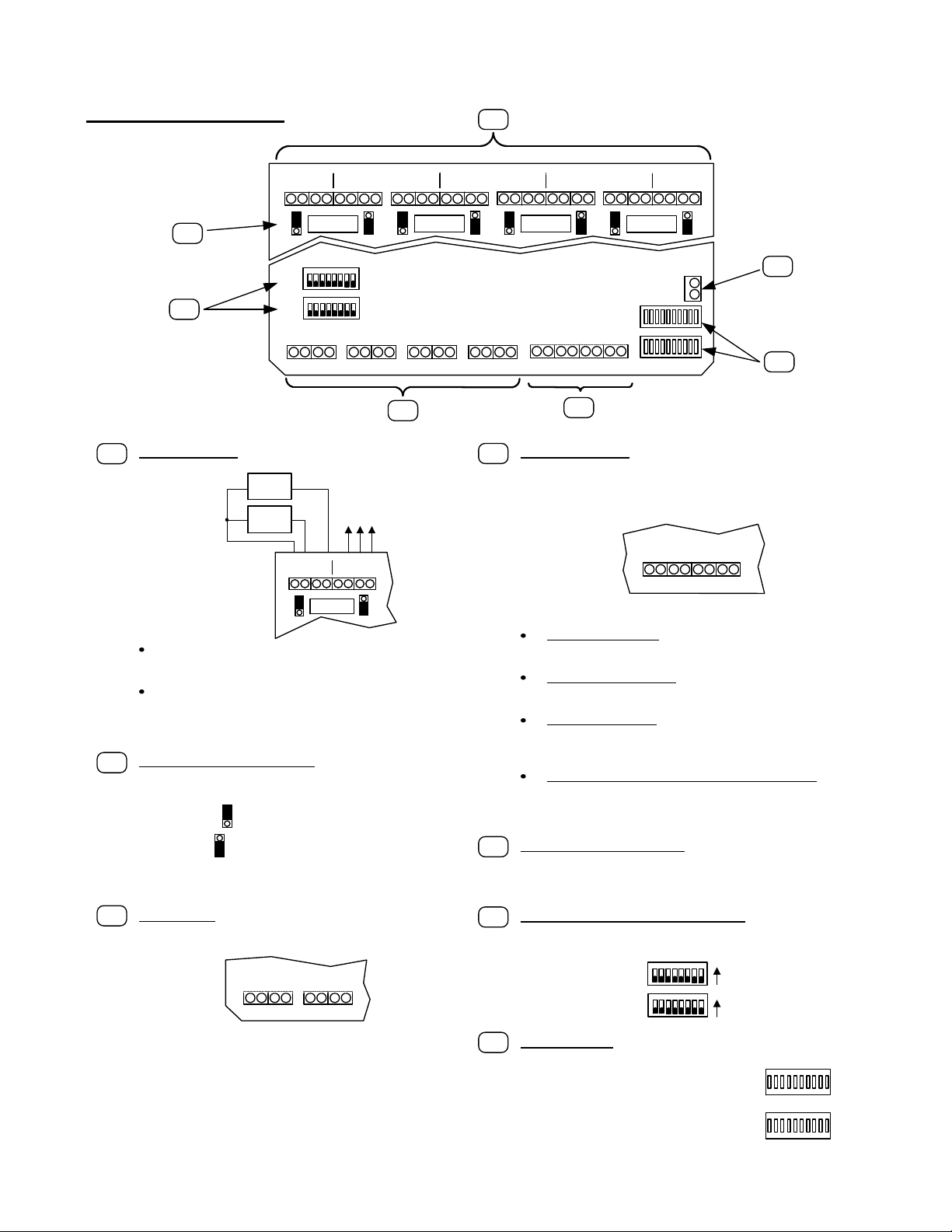
RELAY OUTPUTS – The UR4-8 provides eight (8) individual
1
SPDT relay outputs.
-
-
D
SW2
SW1
Station A Station B Station C Station D Auxiliary Inputs
C A1 C A2 C B1 C B2 C C1 C C2 C D1 C D2 C E 1 C E2 C E3 C E4
FAILSAFE
+
LOCK
FAIL-
+
SECURE
LOCK
OUTPUT 1
(
-
)
W
D
Outputs 1, 3, 5, & 7 are fused. These outputs are typically
used to power the door locking hardware.
Outputs 2, 4, 6, & 8 are non-fused. These outputs are
typically used as auxiliary (monitoring) relays. They may
be used to power a remote status annunciator, or send a
signal to a security panel.
WET/DRY SELECTION JUMPER – Each relay output may be
2
configured as a wet (voltage) or dry output. Use the supplied
jumpers to configure each relay individually.
W
Jumper over top 2 pins = WET
D
W
Jumper over bottom 2 pins = DRY
D
The relay output voltage will be the same as the UR4-8 input
voltage (12 or 24 VDC).
(
-
)
3
NON
C
C
FUSE
OUTPUT 4
(
-
N
)
O
(
N
-
)
C
C
W
W
D
D
UR4-8
4
5
OUTPUT 6 OUTPUT 8
(
NON
-
N
)
C
C
O
FUSE
OUTPUT 7OUTPUT 5
(
N
-
)
C
C
W
W
D
D
NON
C
C
FUSE
(-)
N
N
C
C
O
W
D
5
Power Input
12/24 VDC
+
(-)
7
4
AUXILIARY INPUTS – The UR4-8 provides four (4) individual
dry, optically isolated auxiliary inputs.
NOTE: These input connections are optional and must be wired
as Normally Open connections. The input will only be active when
closed (shorted).
C E 1 C E2 C E3 C E4
}
}
}
Input E1Input
E2
Input E1 – LOCK ALL – When activated, this input will lock
all the doors, until the input is deactivated. Door Monitoring
Inputs will be ignored.
Input E2 – UNLOCK ALL – When activated, this input will
unlock all the doors, until the input is deactivated. Door
Monitoring Inputs will be ignored.
Input E3– LOCKOUT – When activated, this input will cause
all the lock outputs to remain in their current state, and
ignore changes to the Door Monitoring Inputs. Lock/Unlock
All inputs will also ignored.
Input E4 – EMERGENCY RELEASE (FIRE ALARM) –
When activated, this input will simultaneously release all failsafe locks. Door Monitoring Inputs, Lock/Unlock All inputs,
and the Lockout input will be ignored.
INPUT POWER CONNECTION – The UR4-8 must be powered by
a filtered and regulated 12 or 24VDC Power Supply. SDC 600
Series Power Supplies are designed to accommodate and
interface with up to two (2) UR4-8 controllers.
}
Input E3Input
E4
MAIN INPUTS – The UR4-8 provides eight (8) individual
3
optically isolated inputs. The inputs must be connected to a dry
switch.
Station A Station B
C A1 C A2 C B1 C B2
}
}
}
Input A1Input
A2
}
Input B1Input
B2
These inputs may be collectively configured as Normally Open
or Normally Closed inputs.
NOTE: If Normally Closed inputs are selected, all unused
inputs will need to be shorted.
P:\INSTALLATION INST\Power Supplies\INST-UR\INST-UR4-8.vsd REV A1 11-14 Page 2
MODE CONFIGURATION DIP SWITCHES – The UR4-8 utilizes
6
two (2) 8-position dip switch modules for configuring the system
operational modes. They are SW1 and SW2.
1 2 3 45 6
SW2
1 2 3 45 6
SW1
STATUS LIGHTS – The UR4-8 provides diagnostic lights to show
7
ON
7 8
ON
7 8
the status of each individual input and output on the board.
If an input is closed, its corresponding light
will be ON.
O1O2O3O4O5O6O7O
E3E
4
If an output is active, its corresponding light
will be ON.
B1B2C1C2D1D2E1E
A1A
2
8
2
Page 3
IV. Applications
For detailed wiring instructions and setup, select your specific application from the following available modes, and
continue to the page number indicated next to the section title.
Section V – 2, 3, or 4-Door Interlock “A” Setup - Go To Pages 5 & 6
All doors are normally closed and unlocked. Opening any door causes the other doors to lock until the opened door returns to its
normal state.
Section VI – 2, 3, or 4-Door Mantrap “B” Setup – Go To Pages 7 & 8
All doors are normally closed and locked. Each door may be individually unlocked using the Access Control System or a remote
release. Unlocking any door causes the other doors to be incapable of being unlocked until the unlocked door returns to its normal
state.
Section VII – 2, 3, or 4-Door Interlock “C” Setup – Go To Pages 9 & 10
All doors are normally closed. Up to three (3) doors may be normally locked, and the remaining door(s) will be normally unlocked.
The possible configurations are:
2 Doors: Door 1 – Locked, Door 2 – Unlocked
3 Doors: Door 1 – Locked, Doors 2 & 3 – Unlocked
Doors 1 & 2 – Locked, Door 3 – Unlocked
4 Doors: Door 1 – Locked, Doors 2, 3, & 4 – Unlocked
Doors 1 & 2 – Locked, Doors 3 & 4 – Unlocked
Doors 1, 2, & 3 – Locked, Door 4 – Unlocked
Normally Locked doors may be unlocked using the Access Control System. Unlocking or opening any door will lock the unlocked
doors, and make the locked doors incapable of being unlocked, until the unlocked/opened door returns to its normal state.
Section VIII – Dual Relay Control Mode – Go To Pages 11 & 12
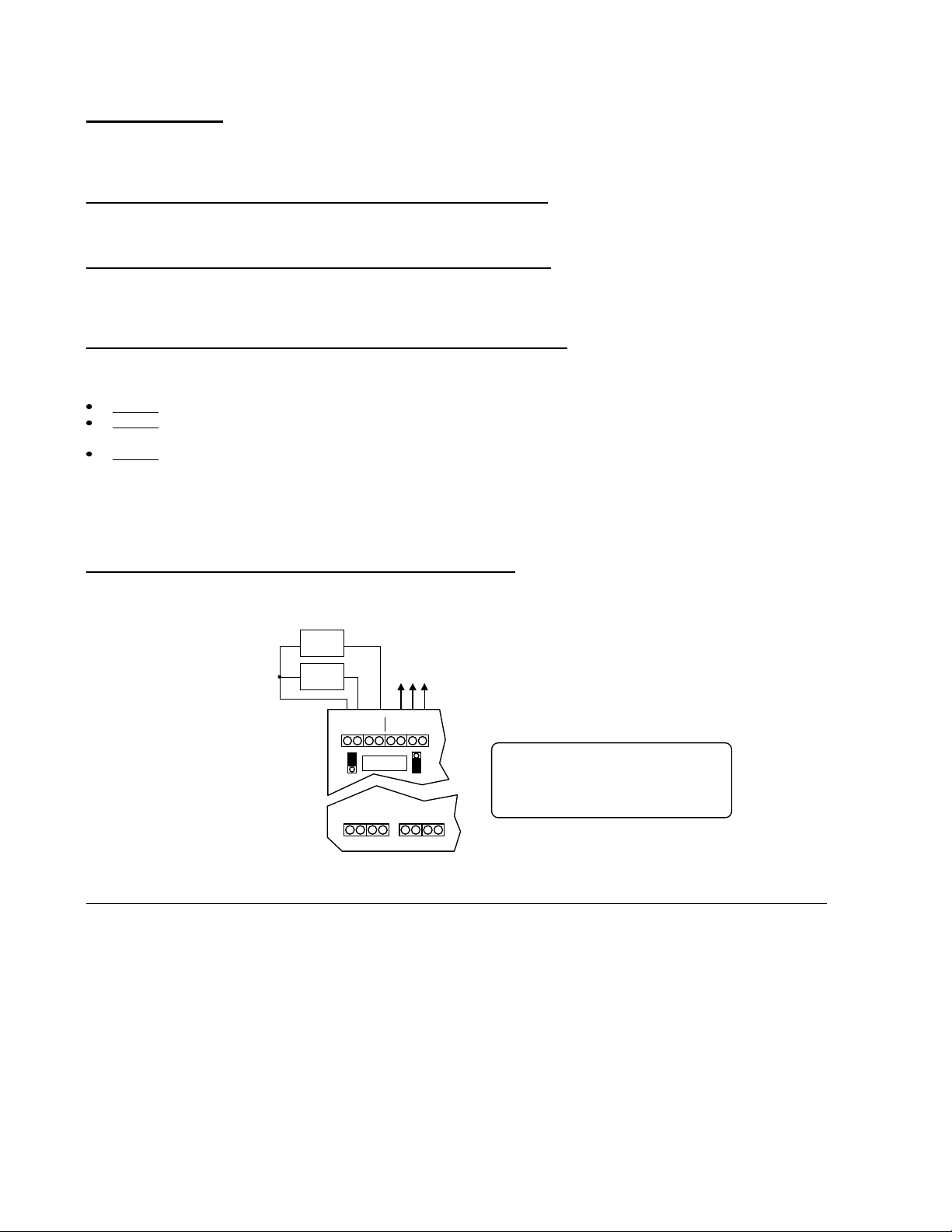
In Dual Relay Control Mode, the UR4-8 operates as four (4) individually controlled relay stations. Each station provides:
(1) Fused, SPDT lock output, wet or dry,
(1) Non-fused, SPDT auxiliary (monitoring) output, wet or dry, and
(2) Dry trigger inputs
FAIL-
SAFE
-
-
LOCK
FAIL-
SECURE
LOCK
+
+
Monitoring
Relay
Output
OUTPUT 1
OUTPUT 2
(
(
-
-
NON
)
C
W
FUSE
D
Station A
C A1 C A2 C B1 C B2
}
}
Input 1Input
N
N
)
C
C
C
O
W
D
2
Station A Inputs activate Outputs 1 & 2
Station B Inputs activate Outputs 3 & 4
Station C Inputs activate Outputs 5 & 6
Station D Inputs activate Outputs 7 & 8
Activating each station’s Input 1 OR Input 2 will trigger the corresponding lock output AND the monitoring output simultaneously.
Each Output Station may be configured as one of the following (Input 1 = CR/Input 2 = CR, Input 1 = TD/ Input 2 = CR (TD reset),
Input 1 = CR (LR reset)/Input 2 = LR, or Input 1 = TD/Input 2 = LR)
As a conventional relay (CR), the lock output relay is only activated while the trigger input is activated. Once the trigger input is
released, the output relay returns to its resting state. The monitoring relay output follows the lock output relay.
As a time delayed relay (TD), the lock output relay is activated by the trigger input. Once the trigger input is released, the output
remains activated for a specified period of time, as configured by the dip switches. The monitoring relay output follows the lock output
relay.
As a latching relay (LR), the lock output relay is activated by trigger Input 2. A single activation and release of trigger Input 2 latches
the lock output relay. The lock output relay remains latched until trigger Input 2 is reactivated or until the Input 1 is momentarily
activated. The monitoring relay output relay follows the lock output relay.
P:\INSTALLATION INST\Power Supplies\INST-UR\INST-UR4-8.vsd REV A1 11-14 Page 3
Page 4
IV. Applications (Continued)
Section IX – Single Relay Control Mode – Go To Pages 13 & 14
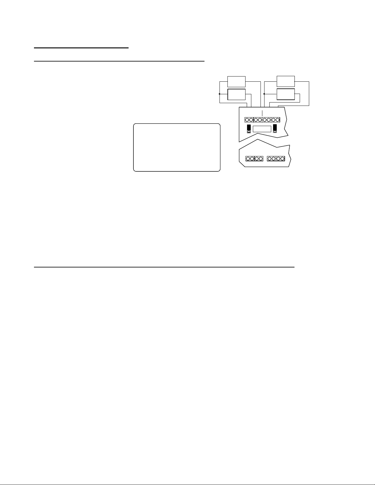
In Single Relay Control Mode, the UR4-8 operates as eight (8) individually controlled relay stations.
Stations A1, B1, C1, & D1 each provide:
(1) Fused, SPDT lock output, wet or dry and
(1) Dry trigger input
Stations A2, B2, C2, & D2 each provide:
(1) Non-fused, SPDT lock output, wet or dry and
(1) Dry trigger input
Station A, Input 1 activates Output 1
Station A, Input 2 activates Output 2
Station B, Input 1 activates Output 3
Station B, Input 2 activates Output 4
Station C, Input 1 activates Output 5
Station C, Input 2 activates Output 6
Station D, Input 1 activates Output 7
Station D, Input 2 activates Output 8
FAIL-
-
-
+
SAFE
LOCK
FAIL-
+
SECURE
LOCK
OUTPUT 1
(
-
NON
)
W
D
Station A
C A1 C A2 C B1 C B2
}
Input 1Input
C
FUSE
C
}
2
-
-
OUTPUT 2
(
-
N
)
C
O
Station B
}
Input 1Input
SECURE
N
C
W
D
}
2
FAILSAFE
LOCK
FAIL-
LOCK
+
+
Each input may be individually configured to operate as a conventional relay or a time delayed relay.
Alternatively, each input may be individually configured to operate as a latching relay or a time delayed relay.
As a conventional relay (CR), the lock output relay is only activated while the trigger input is activated. Once the trigger input is
released, the output relay returns to its resting state.
As a time delayed relay (TD), the lock output relay is activated by the trigger input. Once the trigger input is released, the output
remains activated for a specified period of time, as configured by the dip switches.
As a latching relay (LR), the lock output relay is activated by the trigger Input. A single activation and release of the latching trigger
input latches the lock output relay. The lock output relay remains latched until the latching trigger input is reactivated.
Section X – 2-Door Communicating (Shared) Bath System (Single or Dual) – Go to Page 15 & 16
Both doors are normally closed and unlocked.
System Activation:
Upon entering the bathroom and closing both doors, pressing an Activation button will lock both doors and turn on the indicator lamps
on the Activation button and Emergency Unlock buttons, indicating the bathroom is occupied.
System Deactivation:
When using EMLocks®, pressing the Activation button a second time will unlock both doors and turn off all indicator lamps.
When using fail-safe electric strikes or electrified locksets, operating the inside lever to retract the latch on either door will unlock both
doors and turn off all indicator lamps. Using a key override from the outside to enter either door will also reset the system and unlock
both doors.
Emergency Override:
Emergency Unlock buttons located outside each bathroom door will immediately unlock its specified door and indicate its activation
by causing the button’s indicator lamp to flash. Pressing the Emergency Unlock button a second time will return the door to the
locked state and the indicator lamp will return to a steady lighted state. Pressing the Activation button during an emergency override,
will reset the system and unlock both doors
P:\INSTALLATION INST\Power Supplies\INST-UR\INST-UR4-8.vsd REV A1 11-14 Page 4
Page 5
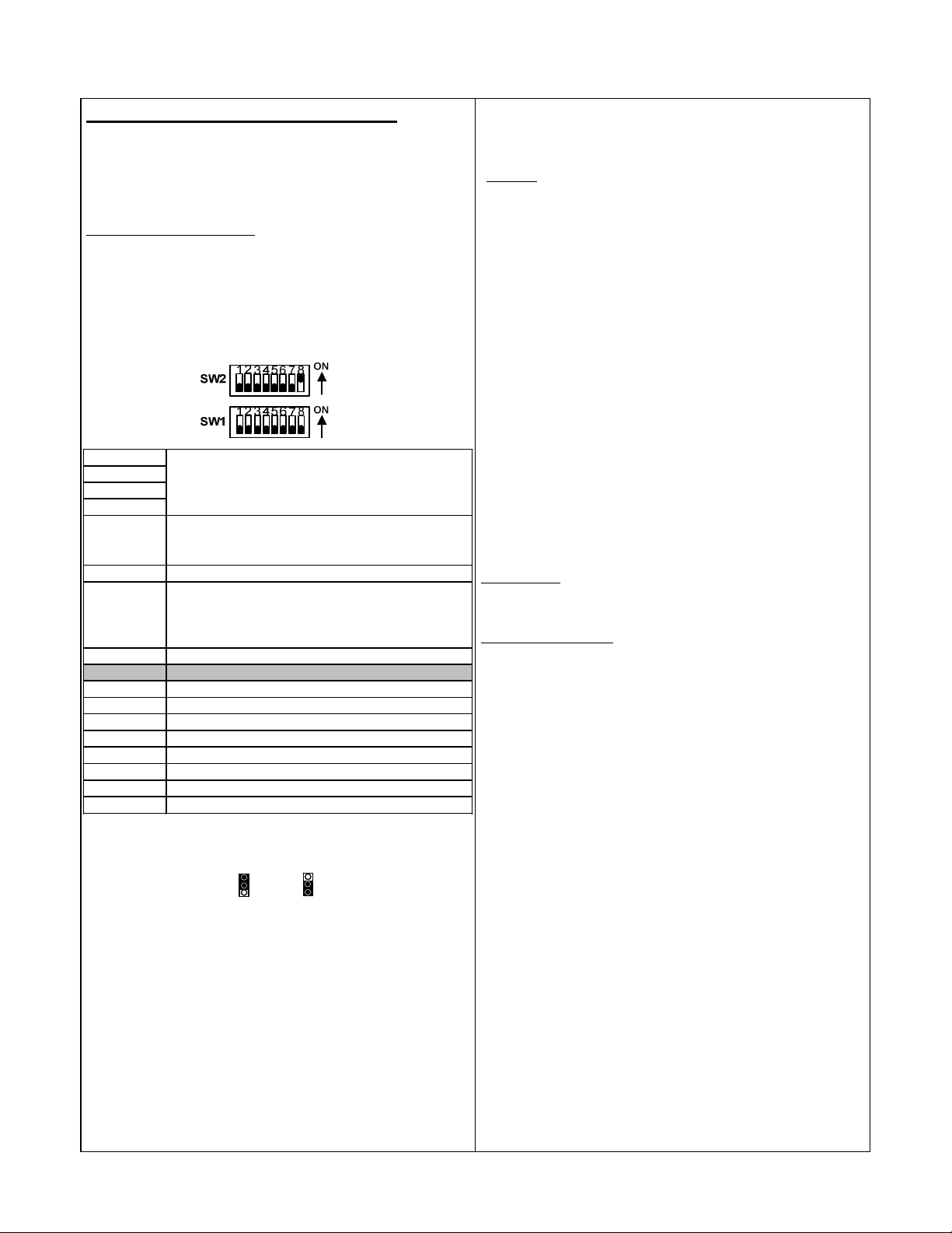
V. 2, 3, or 4-Door Interlock “A” Setup
Sets the operation of all the Monitoring Relay Outputs.
{OFF = Relay w ill follow the Door Monitoring Input;
Follow the installation steps below before applying power to the UR4-8.
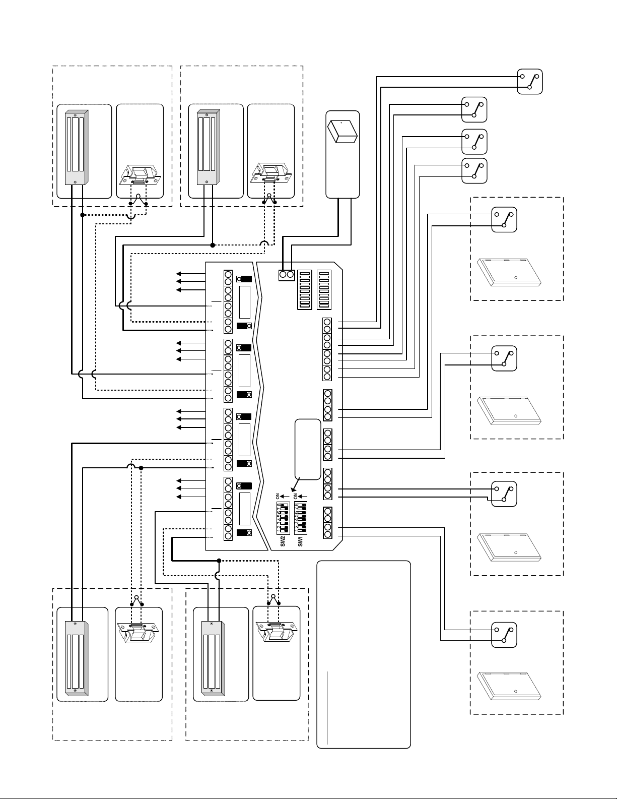
Refer to the INTERLOCK “A” MODE wiring diagram on Page 6.
NOTE: It is assumed that the UR4-8 and locking hardware share the
same power supply.
Interlock “A” Standard Operation:
All doors are normally closed and unlocked. Opening any door causes
the other doors to lock until the opened door returns to its normal state.
Step 1 – Set Dip Switches
Step 3 – Terminate the Lock Power Wiring
Follow the typical Interlock A wiring diagram for fail-safe or fail-secure
locks. Be careful to observe lock voltage polarity.
*
WARNING!:
inductive kickback generated when power is removed from an inductive
load (e.g., electric strikes). Refer to the lock manufacturer's installation
manual or contact the manufacturer for kickback protection
recommendations.
NOTE: All low voltage wiring shall be 18-gauge minimum. The minimum
lock power wire gauge shall be determined by the SDC wire gauge chart.
Signal wire shall be 22-guage minimum.
The UR board Relay Outputs must be protected against
The dip switch settings below are an example of the typical Interlock A
setup shown on Page 6. Adjust dip switches SW2-5 & SW2-7 as needed.
All other dip switches should remain as shown below.
SW2-1 = OFF
SW2-2 = OFF
SW2-3 = OFF
SW2-4 = OFF
SW2-5 = OFF
Sets the polarity of the Door Monitoring Inputs w hen the
door is in the CLOSED position. {OFF = N/O; ON = N/C}
SW2-6 = OFF
SW2-7 = OFF
ON = Relay w ill follow the Lock Output Relay}
SW2-8 = ON
SW1 -1 = OFF
SW1 -2 = OFF
SW1 -3 = OFF
SW1 -4 = OFF
SW1 -5 = OFF
SW1 -6 = OFF
SW1 -7 = OFF
SW1 -8 = OFF
Step 4. Terminate the Door Monitoring Inputs
Connect the Door Monitoring Switches to Input terminals A1, B1, C1, &
D1. This is a required connection for all door stations being used.
Door Monitoring inputs (typically Door Position Switches), should be dry,
Normally Open or Normally Closed switches, depending on the
configuration of Dip Switch 2-5 (Step 1).
NOTE: Dip Switch 2-5 configures the normal state of the Door Monitoring
input when the door is in a CLOSED position. If Normally Closed inputs
are selected, all unused inputs will need to be shorted.
Step 5. Terminate Auxiliary Inputs and Outputs
(Optional)
Auxiliary Inputs – These inputs must be wired as dry, Normally Open
switches. The input will only be active when closed (shorted). Refer to
Page 2 for input descriptions.
Monitoring Relay Outputs – Each door station provides a non-fused,
SPDT monitoring relay. This output may be used to signal a Security
Panel or to activate a Remote Annunciator. The relay is configurable as a
Wet or Dry output (Step 2). The relay activation will follow the Lock Relay
or follow the Door Monitoring Input, depending on the configuration of Dip
Switch 2-7 (Step 1).
Step 6. Connect a 12 or 24VDC Power Source to the
UR4-8 Controller.
Before applying power, verify that all the connections are securely
terminated by gently pulling on each wire.
Step 2 – Configure the Relay Outputs to be Wet
(Voltage) or Dry.
Use the red WET/DRY Selection Jumpers to configure each output.
Refer to Page 2 of this instruction for selection procedure.
On the typical Interlock A wiring diagram, the Lock Relays (Outputs 1, 3,
5, & 7) are configured to be wet outputs.
The Monitoring Relays (Outputs 2, 4, 6, & 8) are dry.
NOTE: It is recommended that any unused relays be configured as dry
outputs.
P:\INSTALLATION INST\Power Supplies\INST-UR\INST-UR4-8.vsd REV A1 11-14 Page 5
W
= WET = DRY
D
Terminate the voltage wiring to the Controller Power Input, as shown on
Page 6. Be careful to observe polarity.
W
D
Verify that all the doors are closed & apply power to the controller.
Step 7. UR4-8 Controller Startup and Operation
Verification.
Verify the polarity of the Door Monitoring Inputs by observing the Status
Lights located on the lower right of the UR4-8 controller.
Status Lights A1, B1, C1, & D1 will be OFF if Dip Switch 2-5 = OFF, or
will be ON if Dip Switch 2-5 = ON.
Test the standard operation of the interlock by opening any door. All
other doors will lock until the unlocked door returns to its normal state
(closed).
Page 6
#3
LOCK
DOOR
LOCK
FAIL-SECURE
(12 OR 24 VDC)
(12 OR 24 VDC)
FAIL-SAFE LOCK
-
-
+
+
MOV
*
Relay
Output
Monitoring
Relay
Output
Monitoring
Relay
Output
Monitoring
Relay
Output
Monitoring
+
(Optional)
OUTPUT 7OUTPUT 5
(Optional)
(Optional)
(Optional)
OUTPUT 6 OUTPUT 8
OUTPUT 4
OUTPUT 3
OUTPUT 2
OUTPUT 1
#4
LOCK
DOOR
(Optional)
LOCKOUT
Series
LOCK
FAIL-SECURE
(12 OR 24 VDC)
(12 OR 24 VDC)
FAIL-SAFE LOCK
-
-
+
MOV
*
*MOV for Inductive Kickback protection.
D
W
N
C
C
N
O
(-)
N
C
FUSE
C
N
O
(-)
N
C
N
(-)
N
C
N
(-)
N
C
N
(-)
N
C
N
(-)
N
C
N
(-)
N
C
N
(-)
D
W
D
W
C
O
C
FUSE
O
D
W
D
W
C
O
C
FUSE
O
D
W
D
W
C
O
C
FUSE
O
D
W
(-)
+
12/24 VDC
Power Input
DIP SWITCHES
Set as shown on
INTERLOCK “A” MODE
SDC 600
ALL
UNLOCK
(Optional)
12/24 VDC
POWER
SUPPLY
-
+
ALL
LOCK
(Optional)
See Step 3 on Pg. 5
DOOR
MONITORING
DOOR
Page 5, Step 1
DOOR
MONITORING
C A1 C A2 C B1 C B2 C C1 C C2 C D1 C D2 C E 1 C E2 C E3 C E4
(Optional)
RELEASE
EMERGENCY
(DPS )
(DPS)
MONITORING
DOOR #3 DOOR #4
(DPS)
*
-
+
(12 OR 24 VDC)
FAIL-SAFE LOCK
#2
DOOR
P:\INSTALLATION INST\Power Supplies\INST-UR\INST-UR4-8.vsd REV A1 11-14 Page 6
MOV
-
+
LOCK
FAIL-SECURE
(12 OR 24 VDC)
LOCK
-
+
(12 OR 24 VDC)
FAIL-SAFE LOCK
#1
DOOR
*
MOV
-
+
LOCK
FAIL-SECURE
(12 OR 24 VDC)
LOCK
DOOR #2
(DPS)
DOOR
MONITORING
DOOR #1
INSTALLATION NOTES:
1. Door Monitoring circuits are shown open when the
door is in the closed position. Use dip switch SW2-5 to
configure the door switch polarity.
2. All Lock Relay Outputs (1, 3, 5, & 7) have been
configured to have wet (voltage) outputs. Lock output
voltage will be the same as the UR4-8 input voltage.
3. Monitoring Relay Outputs have been configured to
follow the Door Monitoring Input.
Page 7
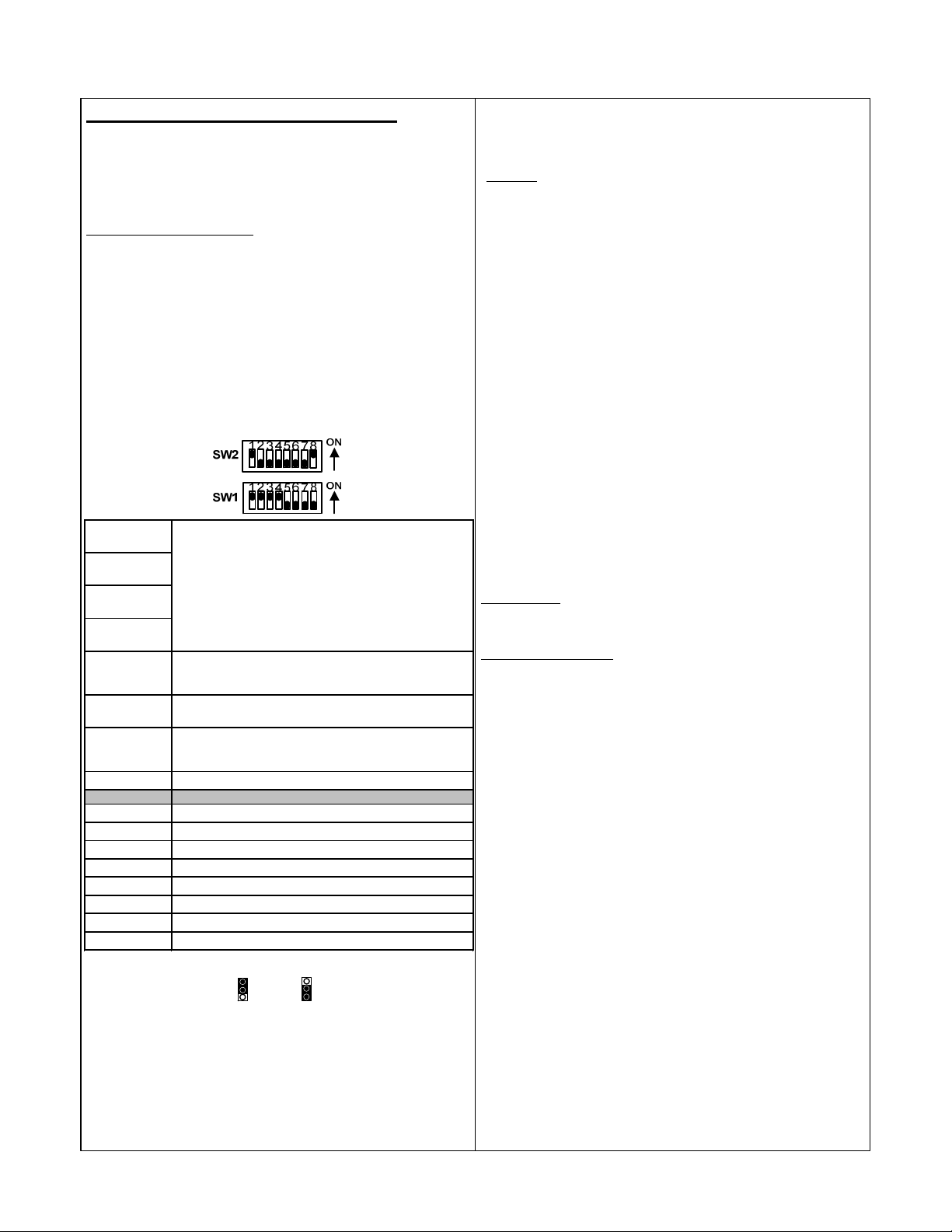
VI. 2, 3, or 4-Door Mantrap “B” Setup
Sets the operat io n of all the Mo nito ring Relay Outputs.
SW2-4 ON = 30 sec., OFF = 0 sec.;
Follow the installation steps below before applying power to the UR4-8.
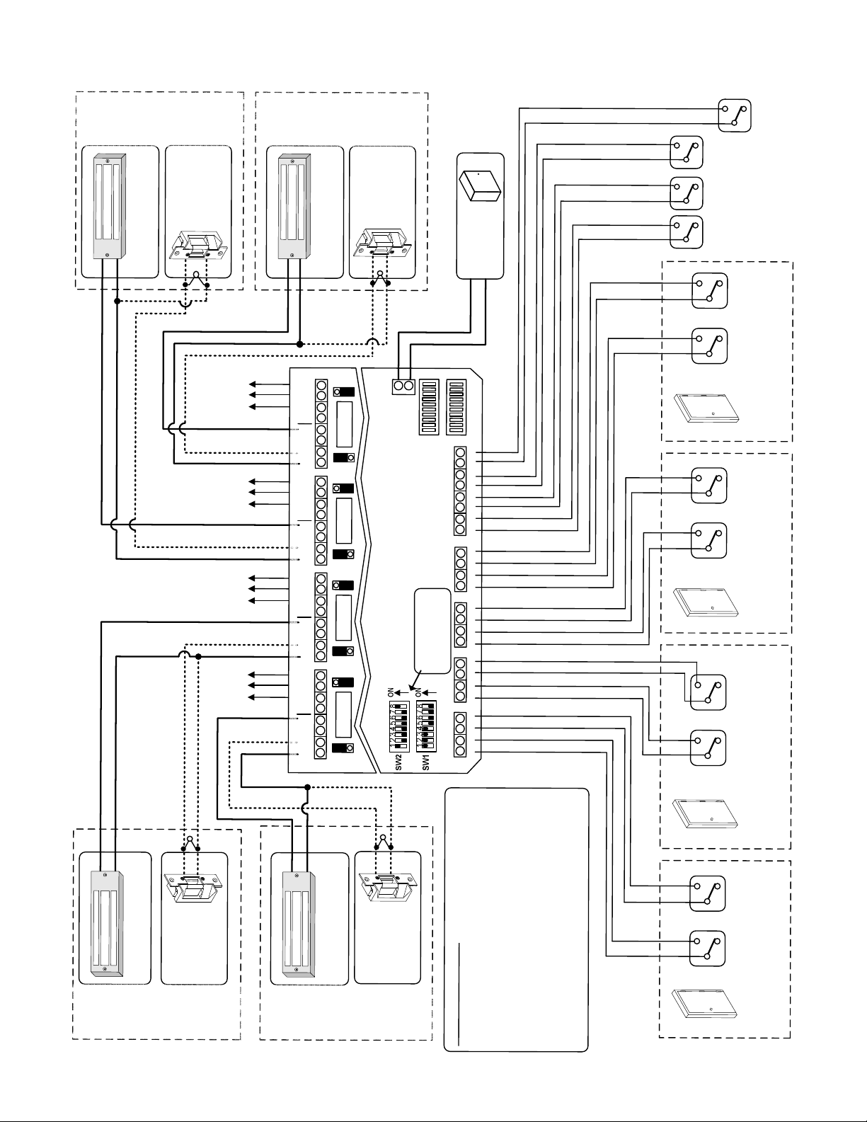
Refer to the MANTRAP “B” MODE wiring diagram on Page 8.
NOTE: It is assumed that the UR4-8 and locking hardware share the
same power supply.
Mantrap “B” Standard Operation:
All doors are normally closed and locked. Each door may be individually
unlocked using the Access Control System or a remote release.
Unlocking any door causes the other doors to be incapable of being
unlocked until the unlocked door returns to its normal state.
The door unlock time will be determined by the Access Control System
and by Dip Switches 2-1 through 2-4 (See Step 1).
Step 3. Terminate the Lock Power Wiring
Follow the typical Mantrap B wiring diagram for fail-safe or fail-secure
locks. Be careful to observe lock voltage polarity.
*
WARNING!:
The UR board Relay Outputs must be protected against
inductive kickback generated when power is removed from an inductive
load (e.g., electric strikes). Refer to the lock manufacturer's installation
manual or contact the manufacturer for kickback protection
recommendations.
NOTE: All low voltage wiring shall be 18-gauge minimum. The minimum
lock power wire gauge shall be determined by the SDC wire gauge chart.
Signal wire shall be 22-guage minimum.
Step 4. Terminate the Access Control and Door
Monitoring Inputs
Step 1 – Set Dip Switches
The dip switch settings below are an example of the typical Mantrap B
setup shown on Page 8. Adjust dip switches SW2-1 thru SW2-7 as
needed. All other dip switches should remain as shown below.
Connect the Door Monitoring Switches to input terminals A1, B1, C1, &
D1. This is a required connection for all door stations being used.
Connect Access Control or remote releases to input terminals A2, B2, C2,
& D2. This is a required connection for all door stations being used.
Door Monitoring and Access Control inputs should be dry, Normally Open
or Normally Closed switches, depending on the configuration of Dip
Switches 2-5 and 2-6, respectively.
NOTE: Dip Switch 2-5 configures the normal state of the Door Monitoring
SW2-1 = ON
SW2-2 = OFF
SW2-3 = OFF
SW2-4 = OFF
SW2-5 = OFF
SW2-6 = OFF
SW2-7 = OFF
SW2-8 = ON
SW1 -1 = ON
SW1 -2 = ON
SW1 -3 = ON
SW1 -4 = ON
SW1 -5 = OFF
SW1 -6 = OFF
SW1 -7 = OFF
SW1 -8 = OFF
SW2-1 thro ugh 2-4 set the unlo ck time o f the Lock Relay.
: This is in addition to your Acces s Contro l System
N O TE
unlo ck time.
SW2-1 ON = 5 sec., OFF = 0 sec.;
SW2-2 ON = 1 0 sec., OFF = 0 sec.;
SW2-3 ON = 20 sec., OFF = 0 sec.;
Switch times are additive. {All OFF = 1 sec.; All ON = 65
sec.}
Sets the polarit y of the Do or M o nitoring Inputs when the
doo r is in the CLOSED and/o r LOCKED po sitio n.
{OFF = N/O; ON = N/C}
Sets the polarit y of A ccess Co nt ro l Inputs when the switch
is in a normal (rest ing) state. {OFF = N/O; ON = N/C}
{OFF = Relay will follo w the Do o r M onito ring Input;
ON = Relay will fo llo w the Lock Output Relay}
Step 2 – Configure the Relay Outputs to be Wet
(Voltage) or Dry.
W
= WET = DRY
D
Use the red WET/DRY Selection Jumpers to configure each output.
Refer to Page 2 of this instruction for selection procedure.
On the typical Mantrap B wiring diagram, the Lock Relays (Outputs 1, 3,
5, & 7) are configured to be wet outputs.
The Monitoring Relays (Outputs 2, 4, 6, & 8) are dry.
NOTE: It is recommended that any unused relays be configured as dry
outputs.
P:\INSTALLATION INST\Power Supplies\INST-UR\INST-UR4-8.vsd REV A1 11-14 Page 7
W
D
input when the door is in a CLOSED and/or LOCKED position. If
Normally Closed inputs are used, all unused inputs will need to be
shorted.
Step 5. Terminate Optional Inputs and Outputs
Auxiliary Inputs – These inputs must be wired as dry, Normally Open
switches. The input will only be active when closed (shorted). Refer to
Page 2 for input descriptions.
Monitoring Relay Outputs – Each door station provides a non-fused,
SPDT monitoring relay. This output may be used to signal a Security
Panel or to activate a Remote Annunciator. The relay is configurable as a
Wet or Dry output (Step 2). The relay activation will follow the Lock Relay
or follow the Door Monitoring Input, depending on the configuration of Dip
Switch 2-7 (Step 1).
Step 6. Connect a 12 or 24VDC Power Source to the
UR4-8 Controller.
Before applying power, verify that all the connections are securely
terminated by gently pulling on each wire.
Terminate the voltage wiring to the Controller Power Input. Be careful to
observe polarity.
Verify that all the doors are closed & apply power to the controller.
Step 7. UR4-8 Controller Startup and Operation
Verification.
Verify the polarity of the Access Control & Door Monitoring Inputs by
observing the Status Lights located on the lower right of the UR4-8
controller.
Status Lights A1, B1, C1, & D1 will be OFF if Dip Switch 2-5 = OFF, or
will be ON if Dip Switch 2-5 = ON.
Status Lights A2, B2, C2, & D2 will be OFF if Dip Switch 2-6 = OFF, or
will be ON if Dip Switch 2-6 = ON.
Test the standard operation of the mantrap by unlocking any door using
the Access Control System or remote release. All other doors will be
incapable of being unlocked until the unlocked door returns to its normal
state (closed & locked).
Page 8
R
K
O
3
C
#
O
O
L
D
)
E
C
R
D
U
V
K
C
K
)
C
C
O
D
L
V
E
4
2
F
A
R
S
O
L
2
I
1
A
(
F
-
+
4
C
E
2
S
O
-
R
L
L
O
I
A
2
1
F
(
-
+
MOV
*
)
g
l
n
t
a
i
y
r
u
n
a
o
p
l
o
t
t
i
i
e
t
u
n
p
R
O
o
O
(
M
)
g
l
n
t
a
i
y
r
u
n
a
o
p
l
o
t
t
i
i
e
t
u
n
p
R
O
o
O
(
M
)
g
l
n
t
a
i
y
r
u
n
a
o
p
l
o
t
t
i
i
t
e
u
n
p
R
O
o
O
(
M
)
g
l
n
t
a
i
y
r
u
n
a
o
p
l
o
t
t
i
i
e
t
u
n
p
R
O
o
O
(
M
R
K
O
4
C
#
O
O
L
D
)
E
C
R
D
U
V
K
)
C
C
O
D
L
V
E
4
2
F
A
R
S
-
O
L
2
I
1
A
(
F
-
+
8
T
U
P
T
U
O
7
T
U
P
T
U
O
6
T
U
P
T
U
O
5
T
U
P
T
U
O
4
T
U
P
T
U
O
3
T
U
P
T
U
O
2
T
U
P
T
U
O
1
T
U
P
T
U
O
W
N
C
C
N
O
(-)
N
C
C
N
O
(-)
W
W
N
C
C
N
O
(-)
N
C
C
N
O
(-)
W
W
N
C
C
N
O
(
-
)
N
C
C
N
O
(-)
W
W
N
C
C
N
O
(
-
)
N
C
C
N
O
(-)
W
K
C
4
C
E
2
O
S
-
R
L
L
O
I
A
2
1
F
(
-
+
MOV
*
*MOV for Inductive Kickback protection.
D
(-)
+
E
S
U
F
D
D
t
u
C
p
D
n
I
V
r
4
e
2
/
w
2
o
1
P
E
D
E
S
U
F
D
D
E
S
U
F
O
M
”
B
“
P
A
R
T
N
A
M
DIP SWITCHES
D
D
E
S
U
F
D
Set as shown on
0
s
0
e
6
i
r
C
e
D
S
S
C
D
Y
R
V
L
E
P
4
W
2
P
/
U
O
2
1
S
P
-
+
See Step 3 on Pg. 7
4
E
C
3
E
C
2
E
C
1
E
C
2
D
C
1
D
C
2
C
C
1
C
C
Page 7, Step 1
2
B
C
1
B
C
2
A
C
1
A
C
T
U
O
K
C
O
L
K
C
O
L
N
U
K
C
O
L
Y
)
C
l
E
a
N
S
n
E
A
o
i
G
E
t
L
R
p
E
E
O
(
R
M
)
E
l
a
n
o
i
t
p
O
(
)
l
a
n
L
o
L
i
t
A
p
O
(
)
l
a
n
L
o
L
i
t
A
p
O
(
L
E
E
S
O
S
T
S
R
A
E
O
R
T
E
C
O
M
N
L
C
E
E
O
A
R
R
C
)
G
S
N
I
A
R
R
B
r
O
O
o
T
O
I
S
D
N
P
O
D
(
M
4
#
R
O
O
D
L
E
E
S
O
S
T
S
R
A
E
O
R
T
E
C
O
M
N
L
C
E
E
O
A
R
R
C
)
G
S
N
I
A
R
R
B
r
O
O
o
T
O
I
S
D
N
P
O
D
(
M
3
#
R
O
O
D
L
E
E
S
O
S
T
S
R
A
E
O
R
T
E
C
O
M
N
L
C
E
E
O
A
R
R
C
)
G
S
N
I
A
R
R
B
r
O
O
o
T
O
I
S
D
N
P
O
D
(
M
P:\IN
-
+
S
TALLATION I
K
)
C
C
O
D
L
V
E
4
2
F
A
R
S
O
L
2
I
1
A
(
F
R
O
O
D
NST\Power S
2
#
+
E
R
U
K
C
C
E
O
S
-
L
L
I
A
F
K
C
O
L
upplies\INST-
r
o
o
.
d
n
&
e
e
6
h
p
-
t
2
O
n
W
y
e
l
l
S
h
a
w
s
m
e
n
r
h
e
o
c
p
t
N
i
o
w
n
n
s
w
w
o
p
i
o
h
d
h
s
s
e
e
s
e
r
r
a
U
a
s
.
t
s
:
n
t
u
i
S
o
p
i
u
E
t
n
c
i
T
i
r
s
i
l
O
o
c
o
N
p
r
g
t
N
d
n
n
i
e
r
o
O
I
s
o
C
t
T
o
i
l
s
A
n
c
s
L
o
e
e
L
c
M
h
A
t
c
r
T
A
n
o
i
S
o
.
N
s
D
I
1
i
8
+
K
C
O
L
*
MOV
-
)
E
C
R
D
U
V
K
C
4
C
E
2
O
S
-
R
L
L
O
I
A
2
1
F
(
11-14 Pag
e
*
MOV
-
)
C
D
V
4
2
R
O
2
1
(
UR\INST-UR4
+
-8.
-
sd RE
v
K
)
C
C
O
D
L
V
E
4
2
F
A
R
S
O
L
2
I
1
A
(
F
R
O
O
D
V
1
#
A1
t
u
o
t
.
p
t
e
n
e
e
.
b
y
t
i
e
r
v
a
a
l
h
o
)
p
7
e
h
&
t
,
e
5
r
,
u
3
g
,
i
f
1
(
n
s
o
t
c
u
o
p
t
t
,
u
y
l
O
e
y
v
i
a
t
l
c
e
e
R
p
k
s
c
e
r
o
,
L
5
l
-
l
2
A
W
.
S
2
d
u
g
e
o
r
a
t
u
l
k
g
o
c
i
f
v
o
n
t
L
o
u
.
c
p
s
t
n
n
i
u
e
8
p
e
-
t
b
4
u
R
o
e
)
e
g
a
t
l
o
v
(
t
e
w
e
v
a
h
o
t
d
e
r
u
g
i
f
n
o
c
.
t
v
U
a
u
e
h
p
h
n
t
s
I
t
s
u
g
a
p
n
i
t
e
r
u
o
m
t
O
i
a
n
y
s
a
o
l
e
e
M
h
t
r
R
e
o
g
b
o
n
l
i
D
l
r
i
e
o
w
t
h
i
t
e
n
g
o
w
a
o
t
M
l
l
l
o
.
o
3
v
f
2
#
R
O
O
D
L
E
E
S
O
S
T
S
R
A
E
O
R
T
E
C
O
M
N
L
C
E
E
O
A
R
R
C
)
G
S
N
I
A
R
R
B
r
O
O
o
T
O
I
S
D
N
P
O
D
(
M
1
#
R
O
O
D
Page 9
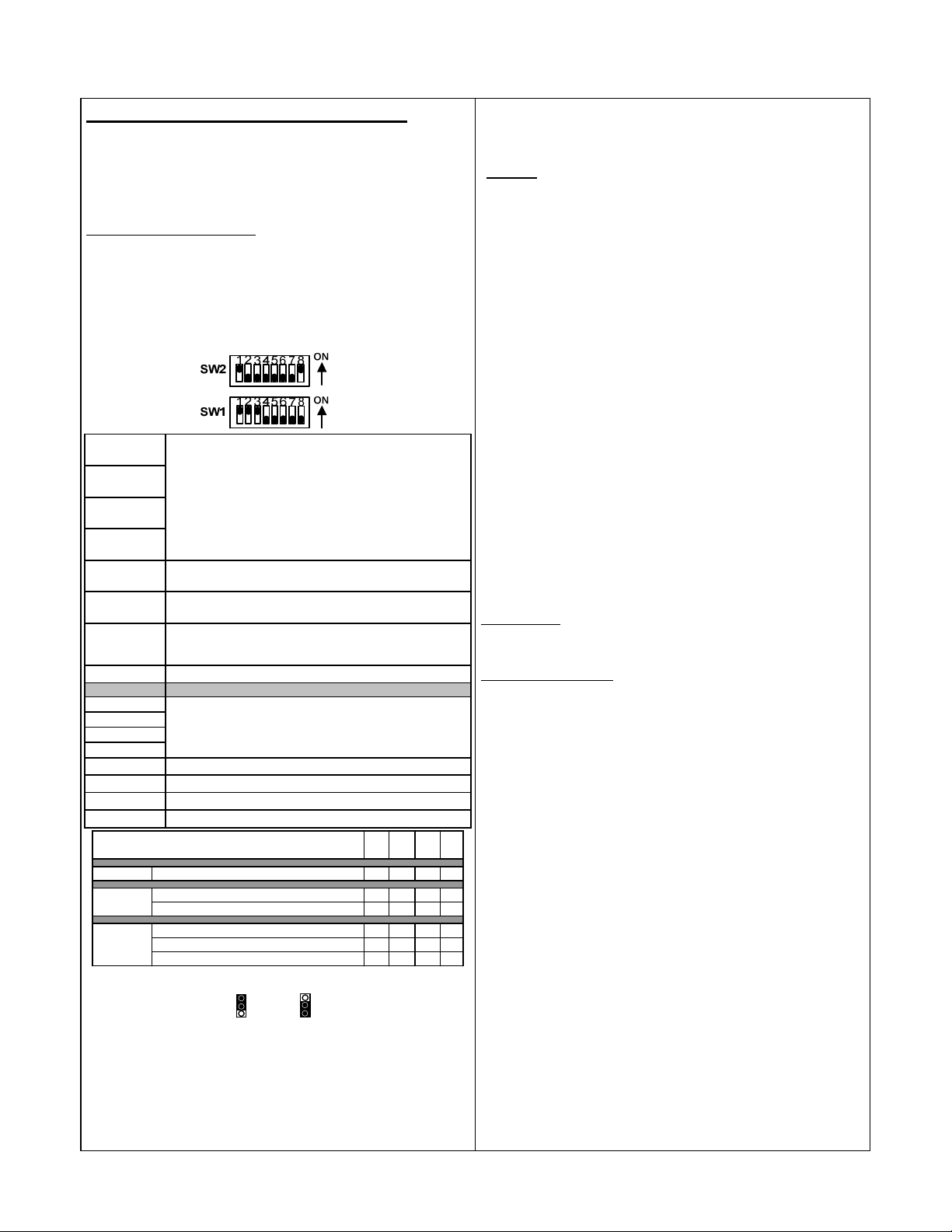
VII. 2, 3, or 4-Door Interlock “C” Setup
SW2-1 ON = 5 sec., OFF = 0 sec.;
SW2-2 ON = 1 0 sec., OFF = 0 sec.;
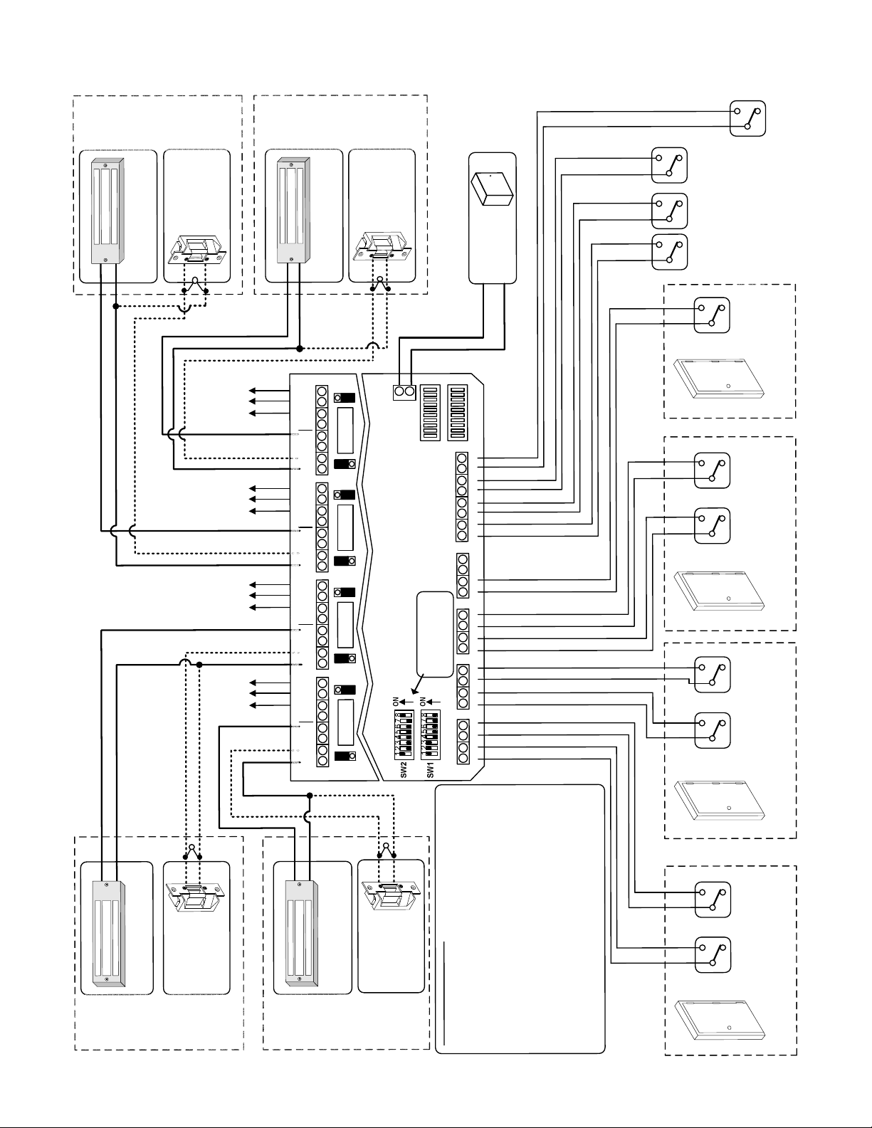
Follow the installation steps below before applying power to the UR4-8.
Refer to the INTERLOCK “C” MODE wiring diagram on Page 10.
NOTE: It is assumed that the UR4-8 and locking hardware share the
same power supply.
Interlock “C” Standard Operation:
Refer to Page 3 – Section VII for method of operation.
Step 1 – Set Dip Switches
The dip switch settings below are an example of a typical Interlock “C”
setup as shown on Page 10.
A) Use dip switches SW1-1 thru SW1-4 to select the Interlock “C” mode
B) Adjust dip switches SW2-1 thru SW2-7 as needed. All other dip
switches should remain as shown below.
Step 3. Terminate the Lock Power Wiring
Follow the typical Interlock “C” wiring diagram for fail-safe or fail-secure
locks. Be careful to observe lock voltage polarity.
*
WARNING!:
The UR board Relay Outputs must be protected against
inductive kickback generated when power is removed from an inductive
load (e.g., electric strikes). Refer to the lock manufacturer's installation
manual or contact the manufacturer for kickback protection
recommendations.
NOTE: All low voltage wiring shall be 18-gauge minimum. The minimum
lock power wire gauge shall be determined by the SDC wire gauge chart.
Signal wire shall be 22-guage minimum.
Step 4. Terminate the Access Control and Door
Monitoring Inputs
NOTE: The Interlock “C” wiring diagram is shown configured for a 4-door
system (3 normally locked doors, and 1 normally unlocked door).
Connect the Door Monitoring Switches to input terminals A1, B1, C1, &
D1. This is a required connection for all door stations being used.
SW2-1 = ON
SW2-2 = OFF
SW2-3 = OFF
SW2-4 = OFF
SW2-5 = OFF
SW2-6 = OFF
SW2-7 = OFF
SW2-8 = ON
SW2-1 through 2-4 set the unlo ck time of the Lock Relay for
normally loc ked do o rs.
N O T E : This is in addition to your Ac ces s Co ntrol System
unlock time.
SW2-3 ON = 20 sec., OFF = 0 sec.;
SW2-4 ON = 30 sec., OFF = 0 sec.;
Switch times are additive. {All OFF = 1 sec.; All ON = 65 sec.}
Sets the polarit y of the Do o r M o nito ring Inputs when the doo r
is in the CLOSED positio n. {OFF = N/O; ON = N/C}
Sets the polarit y of A cc ess Co ntrol Inputs when the switch is in
a norm al (resting) state. {OFF = N/O; ON = N/C}
Sets the operatio n of all the Mo nitoring Relay Outputs .
{OFF = Relay will follo w the Doo r M onito ring Input;
ON = Relay will fo llo w the Lock Output Relay}
Connect Access Control or remote releases to input terminals A2, B2, C2,
& D2. This connection is ONLY required for normally locked doors.
Door Monitoring and Access Control inputs should be dry, Normally Open
or Normally Closed switches, depending on the configuration of Dip
Switches 2-5 and 2-6, respectively.
NOTE: Dip Switch 2-5 configures the normal state of the Door Monitoring
input when the door is in a CLOSED and/or LOCKED position. If
Normally Closed inputs are used, all unused inputs will need to be
shorted.
Step 5. Terminate Optional Inputs and Outputs
Auxiliary Inputs – These inputs must be wired as dry, Normally Open
switches. The input will only be active when closed (shorted). Refer to
Page 2 for input descriptions.
Monitoring Relay Outputs – Each door station provides a non-fused,
SPDT monitoring relay. This output may be used to signal a Security
SW1 -1 =
SW1 -2 =
SW1 -3 =
SW1 -4 =
SW1 -5 = OFF
SW1-6 = OFF
SW1-7 = OFF
SW1-8 = OFF
2-Door Door 1 - Locked; Door 2 Unlocked ON OFF OFF OFF
3-Door
4-Door
Refer to the table below to set Dip Switches 1 -1 thro ugh 1 -4
SW
SW
1 - 2
SW
1 - 3
Interlock "C" Configurations
Door 1 - Locked; Door 2 & 3 - Unlocked ON OFF OFF OFF
Door 1 & 2 - Locked; Door 3 - Unlocked ON ON OFF OFF
Door 1 - Locked; Doors 2, 3 & 4 - Unlocked ON OFF OFF OFF
Doors 1 & 2 - Locked; Doors 3 & 4 - Unlocked ON ON OFF OFF
Doors 1, 2, & 3 - Locked; Door 4 - Unlocked ON ON ON OFF
1 - 1
Step 2 – Configure the Relay Outputs to be Wet
(Voltage) or Dry.
Use the red WET/DRY Selection Jumpers to configure each output.
Refer to Page 2 of this instruction for selection procedure.
On the typical Interlock C wiring diagram, the Lock Relays (Outputs 1, 3,
5, & 7) are configured to be wet outputs. The Monitoring Relays (Outputs
2, 4, 6, & 8) are dry.
NOTE: It is recommended that any unused relays be configured as dry
W
= WET = DRY
D
W
D
Panel or to activate a Remote Annunciator. The relay is configurable as a
Wet or Dry output (Step 2). The relay activation will follow the Lock Relay
or follow the Door Monitoring Input, depending on the configuration of Dip
Switch 2-7 (Step 1).
Step 6. Connect a 12 or 24VDC Power Source to the
UR4-8 Controller.
Before applying power, verify that all the connections are securely
terminated by gently pulling on each wire.
SW
1 -4
Terminate the voltage wiring to the Controller Power Input. Be careful to
observe polarity.
Verify that all the doors are closed & apply power to the controller.
Step 7. UR4-8 Controller Startup and Operation
Verification.
Verify the polarity of the Access Control & Door Monitoring Inputs by
observing the Status Lights located on the lower right of the UR4-8
controller.
Status Lights A1, B1, C1, & D1 will be OFF if Dip Switch 2-5 = OFF, or
will be ON if Dip Switch 2-5 = ON.
Status Lights A2, B2, & C2 will be OFF if Dip Switch 2-6 = OFF, or will be
ON if Dip Switch 2-6 = ON.
Test the standard operation of the interlock by unlocking any door or by
opening the unlocked door(s). All other doors will be incapable of being
opened/unlocked until the opened door returns to its normal state.
outputs.
P:\INSTALLATION INST\Power Supplies\INST-UR\INST-UR4-8.vsd REV A1 11-14 Page 9
Page 10
R
O
O
D
K
)
C
C
O
D
L
V
4
E
2
F
A
R
S
-
O
L
2
I
1
A
(
F
-
+
-
+
K
)
C
C
O
D
L
V
E
4
2
F
A
R
S
-
O
L
2
I
1
A
(
F
P:\INSTALLATION INS
K
3
C
#
O
L
)
E
C
R
D
U
V
K
C
4
C
E
2
S
O
-
R
L
L
O
I
A
2
1
F
(
-
+
MOV
g
n
i
r
o
t
i
n
o
M
g
n
i
r
o
t
i
n
o
M
g
n
i
r
o
t
i
n
o
M
g
n
i
r
o
t
i
n
o
M
*
MOV
-
+
)
E
C
R
D
U
V
K
C
4
C
E
2
O
S
-
R
L
L
O
I
A
2
1
F
(
R
K
2
O
C
#
O
O
L
D
\Power Supplies\INST-UR\I
T
R
K
4
O
C
#
O
O
L
D
)
E
C
R
D
U
V
K
)
C
C
O
D
L
V
E
4
2
F
A
R
S
-
O
L
2
I
1
A
(
F
-
+
*
)
l
t
a
y
u
n
a
p
l
o
t
i
t
e
u
p
R
O
O
(
)
l
t
a
y
u
n
a
p
l
o
t
i
t
e
u
p
R
O
O
(
)
l
t
a
y
u
n
a
p
l
o
t
i
e
t
u
p
R
O
O
(
)
l
t
a
y
u
n
a
p
l
o
t
i
e
t
u
p
R
O
O
(
8
T
U
P
T
U
O
7
T
U
P
T
U
O
6
T
U
P
T
U
O
5
T
U
P
T
U
O
4
T
U
P
T
U
O
3
T
U
P
T
U
O
2
T
U
P
T
U
O
1
T
U
P
T
U
O
W
C
N
C
N
O
(-)
N
C
C
N
O
(-)
W
W
N
C
C
N
O
(-)
N
C
C
O
N
(-)
W
W
N
C
C
N
O
(-)
N
C
C
N
O
(-)
W
W
N
C
C
N
O
(-)
N
C
C
O
N
(-)
W
K
C
4
C
E
2
O
S
-
R
L
L
O
I
A
2
1
F
(
-
+
MOV
*
*MOV for Inductive Kickback protection. See Step 3 on Pg. 9
D
(-)
+
E
D
O
M
”
C
“
K
t
u
C
p
D
n
I
V
r
4
e
2
/
w
2
o
1
P
E
S
U
F
D
D
E
S
U
F
D
D
C
E
S
U
F
D
D
E
S
U
F
D
O
L
R
E
T
N
I
Page 9, Step 1
DIP SWITCHES
Set as shown on
*
MOV
-
+
K
C
O
L
E
F
A
S
L
I
A
F
R
O
O
D
ST-UR4-8.vsd REV A1
N
)
C
D
V
4
2
R
O
2
1
(
K
1
C
#
O
L
-
+
)
E
C
R
D
U
V
:
K
C
4
C
E
O
S
-
L
L
I
A
F
11-14 Page 10
S
2
E
T
R
O
O
2
N
1
(
N
O
I
T
A
L
L
A
T
S
N
I
0
0
s
6
e
i
r
C
e
D
S
S
C
D
Y
R
V
L
E
P
4
W
2
P
/
U
O
2
1
S
P
-
+
4
E
C
3
E
C
2
E
C
1
E
C
2
D
C
1
D
C
2
C
C
1
C
C
2
B
C
1
B
C
2
A
C
1
A
C
r
,
n
o
i
5
o
-
s
i
2
D
r
.
W
o
n
S
o
e
d
&
p
e
O
6
-
h
t
y
2
l
l
n
W
a
e
S
m
h
r
s
w
o
e
h
n
N
c
e
t
n
i
p
w
o
w
o
s
n
h
p
w
s
i
o
d
s
i
h
e
t
s
s
u
e
U
p
r
a
n
.
i
n
s
l
t
o
i
o
i
r
t
u
t
i
c
n
s
r
i
o
o
c
p
C
g
s
d
n
s
e
i
r
e
s
o
c
o
l
t
c
i
c
n
A
e
o
.
h
t
M
1
t
u
p
t
u
n
o
e
k
e
c
b
o
e
L
v
.
a
s
h
t
)
.
u
7
y
p
t
t
i
&
r
u
,
a
o
l
5
)
o
,
e
p
3
g
,
e
a
1
t
h
l
(
t
o
s
e
v
t
(
r
u
u
t
p
e
g
t
i
f
u
w
n
O
e
o
v
y
c
a
a
l
o
h
t
e
,
o
R
t
y
l
k
d
e
c
e
v
r
i
o
t
u
L
c
l
g
e
l
i
f
p
A
n
s
o
.
e
r
2
c
.
s
o
t
.
e
g
a
t
l
o
v
t
u
p
n
i
8
4
R
U
e
h
t
s
a
e
m
a
s
e
h
t
e
b
l
l
i
w
e
g
a
t
l
o
v
t
u
d
p
y
e
n
l
r
I
n
l
u
O
o
g
i
r
f
t
.
n
n
s
t
o
o
u
c
C
p
n
s
n
I
e
s
e
e
g
b
c
n
i
c
e
r
o
t
i
n
o
M
r
o
o
D
e
r
i
u
q
e
r
s
r
o
o
d
l
l
A
.
3
.
t
v
A
u
a
e
h
p
r
i
n
s
I
u
t
q
g
u
e
n
p
r
i
t
r
u
s
o
r
t
O
i
o
n
y
o
o
a
d
l
M
e
d
r
e
R
k
o
g
c
o
n
o
i
D
r
L
e
o
t
y
h
i
l
t
l
n
a
o
w
m
o
M
r
l
l
o
.
o
f
4
N
)
T
l
a
U
n
O
o
i
K
t
C
p
O
O
(
L
)
l
K
a
C
n
L
o
O
L
i
t
L
A
p
N
O
U
(
)
l
a
K
n
L
o
C
L
i
t
O
A
p
L
O
(
Y
)
C
l
E
a
N
S
n
E
A
o
i
G
E
t
L
R
p
E
E
O
(
R
M
E
G
N
I
)
R
R
S
O
O
P
T
O
I
D
(
D
N
O
M
4
#
R
O
O
D
L
E
E
S
O
S
T
S
R
A
O
E
R
T
E
C
M
O
L
N
C
E
E
O
A
R
R
C
)
G
S
N
I
A
R
R
B
r
O
O
o
T
O
I
S
D
N
P
O
D
(
M
3
#
R
O
O
D
L
E
E
S
O
S
T
S
R
A
O
E
R
T
E
C
M
O
L
N
C
E
E
O
A
R
R
C
)
G
S
N
I
A
R
R
B
r
O
O
o
T
O
I
S
D
N
P
O
D
(
M
2
#
R
O
O
D
L
E
E
S
O
S
T
S
R
A
O
E
R
T
E
C
M
O
L
N
C
E
E
O
A
R
R
C
)
G
S
N
I
A
R
R
B
r
O
O
o
T
O
I
S
D
N
P
O
D
(
M
1
#
R
O
O
D
Page 11
VIII. Dual Relay Control Mode Setup
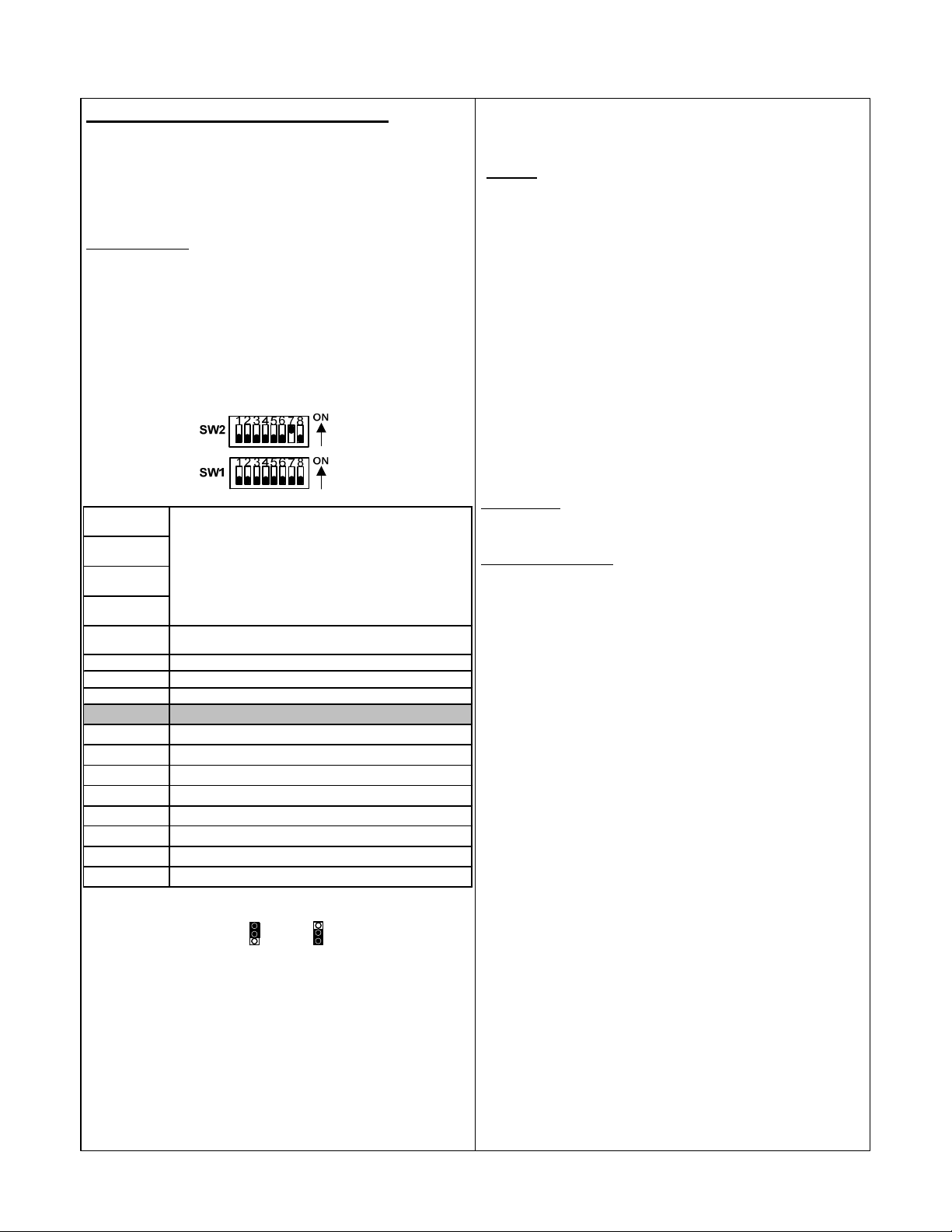
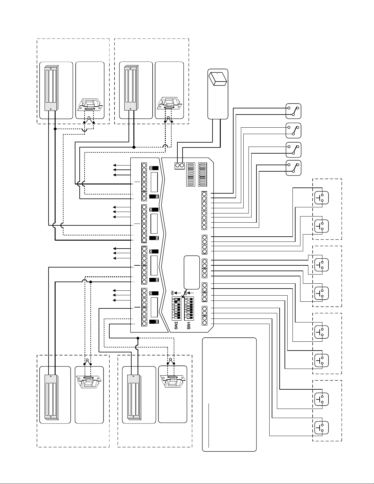
Follow the installation steps below before applying power to the UR4-8.
Refer to the DUAL RELAY CONTROL MODE wiring diagram on Page
12.
NOTE: It is assumed that the UR4-8 and locks will share the same power
supply.
Standard Operation:
Refer to Page 3 – Section VIII for method of operation.
Step 1 – Set Dip Switches
The dip switch settings below are an example of the typical Dual Relay
Control Mode Setup as shown on Page 12.
A) Use dip switches SW1-1 through SW1-8 to select the operation of
each trigger input: CR, TD, or LR.
B) Adjust dip switches SW2-1 thru SW2-5 as needed. All other dip
switches shall remain as shown below.
SW2-1 = OFF
SW2-2 = OFF
SW2-3 = OFF
SW2-4 = OFF
SW2-5 = OFF
SW2-6 = OFF
SW2-7 = ON
SW2-8 = OFF
SW1 -1 = OFF
SW1 -2 = OFF
SW1 -3 = OFF
SW1 -4 = OFF
SW1 -5 = OFF
SW1 -6 = OFF
SW1 -7 = OFF
SW1 -8 = OFF
Step 2 – Configure the Relay Outputs to be Wet
(Voltage) or Dry.
Use the red WET/DRY Selection Jumpers to configure each output.
Refer to Page 2 of this instruction for selection procedure.
On the typical Dual Relay Control Mode wiring diagram, the Lock Relays
(Outputs 1, 3, 5, & 7) are configured to be wet outputs. The Monitoring
Relays (Outputs 2, 4, 6, & 8) are dry.
The relay output voltage will be the same as the UR4-8 input voltage (12
or 24 VDC).
When using TD mode, SW 2-1 through 2-4 sets the unlo ck
delay time of the relays.
SW2-1 ON = 5 sec., OFF = 0 sec.;
SW2-2 ON = 1 0 sec., OFF = 0 sec.;
SW2-3 ON = 20 sec., OFF = 0 sec.;
SW2-4 ON = 30 sec., OFF = 0 sec.;
Switch times are additive. {All OFF = 1 sec.; All ON = 65 sec.}
Sets the polarity of A LL the trigger inputs when the trigger is
in a non-ac tivated stat e. {OFF = N/O; ON = N/C }
Statio n A, Input 1 M o de Selection {OFF = CR; ON = TD}
Statio n A, Input 2 Mo de Selectio n {OFF = CR; ON = LR}
Statio n B, Input 1 M o de Selection {OFF = CR; ON = TD}
Statio n B, Input 2 Mo de Selectio n {OFF = CR; ON = LR}
Statio n C, Input 1 Mo de Selectio n {OFF = CR; ON = TD}
Statio n C, Input 2 M o de Select io n {OFF = CR; ON = LR}
Statio n D, Input 1 M o de Selection {OFF = CR; ON = TD}
Statio n D, Input 2 M o de Select io n {OFF = CR; ON = LR}
W
= WET = DRY
D
W
D
Step 3. Terminate the Lock Power Wiring
Follow the typical Dual Relay Control Mode wiring diagram for fail-safe or
fail-secure locks. Be careful to observe lock voltage polarity.
*
WARNING!:
The UR board Relay Outputs must be protected against
inductive kickback generated when power is removed from an inductive
load (e.g., electric strikes). Refer to the lock manufacturer's installation
manual or contact the manufacturer for kickback protection
recommendations.
NOTE: All low voltage wiring shall be 18-gauge minimum. The minimum
lock power wire gauge shall be determined by the SDC wire gauge chart.
Signal wire shall be 22-guage minimum.
Step 4. Terminate the Station Trigger Inputs
Connect each station’s trigger input 1 and input 2, as required.
All the trigger inputs should be dry, momentary, Normally Open or
Normally Closed switches, depending on the configuration of Dip Switch
2-5 (Step 1).
NOTE: Dip Switch 2-5 configures the normal (resting) state of the trigger
input. If Normally Closed inputs are used, all unused trigger inputs will
need to be shorted.
Step 5. Terminate Optional Inputs and Outputs
Auxiliary Inputs – These inputs must be wired as dry, Normally Open
switches. The input will only be active when closed (shorted). Refer to
Page 2 for input descriptions.
Monitoring Relay Outputs – Each door station provides a non-fused,
SPDT monitoring relay. This output may be used to signal a Security
Panel or to activate a Remote Annunciator. The relay is configurable as a
Wet or Dry output (Step 2). The relay activation will follow the Lock
Relay.
Step 6. Connect a 12 or 24VDC Power Source to the
UR4-8 Controller.
Before applying power, verify that all the connections are securely
terminated by gently pulling on each wire.
Terminate the voltage wiring to the Controller Power Input. Be careful to
observe polarity.
Verify that all the trigger inputs are in their normal (resting) state & apply
power to the controller.
Step 7. UR4-8 Controller Startup and Operation
Verification.
Verify the polarity of each Station trigger input by observing the Status
Lights located on the lower right of the controller.
Status Lights A1, A2, B1, B2, C1, C2, D1 & D2 will be OFF if Dip Switch
2-5 = OFF, or will be ON if Dip Switch 2-5 = ON.
Test the standard operation of each station control relay by momentarily
pressing the trigger input.
In CR mode, the respective door will unlock while the trigger input is
activated, and relock when the trigger is released.
In TD mode, the respective door will unlock when the trigger input is
activated. Releasing the trigger input will start the unlock timer and the
door will remain unlocked. The door will relock after the set unlock time
has expired.
NOTE: It is recommended that any unused relays be configured as dry
outputs.
In LR mode, the respective door will unlock when the trigger input is
momentarily activated and released. The door will remained unlocked
indefinitely until the trigger input is reactivated.
P:\INSTALLATION INST\Power Supplies\INST-UR\INST-UR4-8.vsd REV A1 11-14 Page 11
Page 12
C
LOCK
Station
LOCK
FAIL-SECURE
(12 OR 24 VDC)
(12 OR 24 VDC)
FAIL-SAFE LOCK
-
-
+
+
MOV
*
Relay
Output
Monitoring
Relay
Output
Monitoring
Relay
Output
Monitoring
Relay
Output
Monitoring
+
(Optional)
OUTPUT 7OUTPUT 5
(Optional)
(Optional)
(Optional)
OUTPUT 6 OUTPUT 8
OUTPUT 4
OUTPUT 3
OUTPUT 2
OUTPUT 1
D
LOCK
Station
Series
LOCK
FAIL-SECURE
(12 OR 24 VDC)
(12 OR 24 VDC)
FAIL-SAFE LOCK
-
D
W
N
C
C
N
O
(-)
N
C
FUSE
C
N
O
(-)
N
C
N
(-)
N
C
N
(-)
N
C
N
(-)
N
C
N
(-)
N
C
N
(-)
N
C
N
(-)
D
W
D
W
C
O
C
FUSE
O
D
W
D
W
C
O
C
FUSE
O
D
W
D
W
C
O
C
FUSE
O
D
W
-
+
Power Input
(-)
+
*MOV for Inductive Kickback protection.
*
12/24 VDC
MOV
MODE
Page 11, Step 1
DIP SWITCHES
DUAL RELAY CONTROL
Set as shown on
SDC 600
12/24 VDC
POWER
SUPPLY
-
+
See Step 3 on Pg. 11
C A1 C A2 C B1 C B2 C C1 C C2 C D1 C D2 C E1 C E2 C E3 C E4
(Optional)
RELEASE
EMERGENCY
(Optional)
LOCKOUT
ALL
UNLOCK
(Optional)
ALL
LOCK
(Optional)
INPUT 2
INPUT 1
INPUT 2
INPUT 1
INPUT 2
*
-
+
(12 OR 24 VDC)
FAIL-SAFE LOCK
MOV
-
+
LOCK
FAIL-SECURE
(12 OR 24 VDC)
B
LOCK
Station
P:\INSTALLATION INST\Power Supplies\INST-UR\INST-UR4-8.vsd REV A1 11-14 Page 12
-
+
(12 OR 24 VDC)
FAIL-SAFE LOCK
A
Station
*
MOV
-
+
LOCK
FAIL-SECURE
(12 OR 24 VDC)
LOCK
INPUT 1
INPUT 2
Station A Triggers Station B Triggers Station C Triggers Station D Triggers
INPUT 1
INSTALLATION NOTES:
1. All inputs are shown configured as Normally Open
switches.
2. All Lock Relay Outputs (1, 3, 5, & 7) have been
configured to have wet (voltage) outputs. Lock output
voltage will be the same as the UR4-8 input voltage.
3. The Monitoring Relay Output will always follow the
lock relay.
Page 13
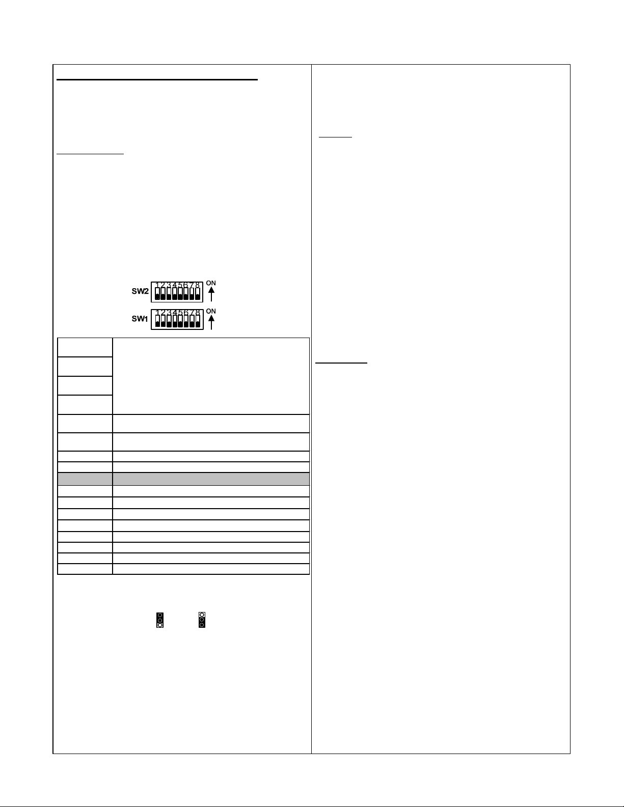
IX. Single Relay Control Mode Setup
Follow the installation steps below before applying power to the UR4-8.
Refer to the SINGLE RELAY CONTROL MODE wiring diagram on Page
14.
NOTE: It is assumed that the UR4-8 and locks will share the same power
supply.
Standard Operation:
Refer to Page 4 – Section IX for method of operation.
Step 1 – Set Dip Switches
The dip switch settings below are an example of the typical Single Relay
Control Mode Setup as shown on Page 14.
A) Use dip switches SW1-1 through SW1-8 to select the operation of
each trigger input: CR, TD, or LR.
If dip switch SW2-6 = OFF, each input is selectable as a CR or TD only.
If dip switch SW2-6 = ON, each input is selectable as a LR or TD only.
B) Adjust dip switches SW2-1 thru SW2-5 as required. All other dip
switches should remain as shown below.
Step 3. Terminate the Lock Power Wiring
Follow the Single Relay Control Mode wiring diagram for fail-safe or failsecure locks. Be careful to observe lock voltage polarity.
*
WARNING!:
The UR board Relay Outputs must be protected against
inductive kickback generated when power is removed from an inductive
load (e.g., electric strikes). Refer to the lock manufacturer's installation
manual or contact the manufacturer for kickback protection
recommendations.
NOTE: All low voltage wiring shall be 18-gauge minimum. The minimum
lock power wire gauge shall be determined by the SDC wire gauge chart.
Signal wire shall be 22-guage minimum.
Step 4. Terminate the Station Trigger Inputs
Connect each station’s trigger input as required.
All the trigger inputs should be dry, momentary, Normally Open or
Normally Closed switches, depending on the configuration of Dip Switch
2-5 (Step 1).
NOTE: Dip Switch 2-5 configures the normal (resting) state of the trigger
input. If Normally Closed inputs are used, all unused trigger inputs will
need to be shorted.
SW2-1 = OFF
SW2-2 = OFF
SW2-3 = OFF
SW2-4 = OFF
SW2-5 = OFF
SW2-6 = OFF
SW2-7 = OFF
SW2-8 = OFF
SW1 -1 = OFF St atio n 1 Mo de Selectio n {OFF = CR or LR; ON = TD}
SW1 -2 = OFF Station 2 M o de Selectio n {OFF = CR or LR; ON = TD}
SW1 -3 = OFF
SW1 -4 = OFF
SW1 -5 = OFF Station 5 M o de Selectio n {OFF = CR or LR; ON = TD}
SW1 -6 = OFF Station 6 M o de Selectio n {OFF = CR or LR; ON = TD}
SW1 -7 = OFF Station 7 M o de Selectio n {OFF = CR or LR; ON = TD}
SW1 -8 = OFF Station 8 M o de Selectio n {OFF = CR or LR; ON = TD}
When using TD mode, SW 2-1 thro ugh 2-4 set the unloc k
delay time of the Lock Relay.
SW2-1 ON = 5 sec., OFF = 0 sec.;
SW2-2 ON = 1 0 sec., OFF = 0 sec.;
SW2-3 ON = 20 sec., OFF = 0 sec.;
SW2-4 ON = 30 sec., OFF = 0 sec.;
Switch times are additive. {All OFF = 1 sec.; All ON = 65 sec.}
Sets the polarity of ALL the trigger inputs when the trigger is in
a non-act ivated state. {OFF = N/O; ON = N/C}
{OFF = Each trigger input is select able as CR o r TD o nly;
ON = Each trigger input is selectable as LR or TD o nly}
Station 3 M o de Selectio n {OFF = CR or LR; ON = TD}
Station 4 M o de Selectio n {OFF = CR or LR; ON = TD}
Step 2 – Configure the Relay Outputs to be Wet
(Voltage) or Dry.
W
= WET = DRY
D
Use the red WET/DRY Selection Jumpers to configure each output.
Refer to Page 2 of this instruction for selection procedure.
On the typical Single Relay Control Mode wiring diagram, all relay outputs
are configured as wet outputs.
The relay output voltage will be the same as the UR4-8 input voltage (12
or 24 VDC).
NOTE: It is recommended that any unused relays be configured as dry
outputs.
W
D
Step 5. Terminate Optional Inputs and Outputs
Auxiliary Inputs – These inputs must be wired as dry, Normally Open
switches. The input will only be active when closed (shorted). Refer to
Page 2 for input descriptions.
Step 6. Connect a 12 or 24VDC Power Source to the
UR4-8 Controller.
Before applying power, verify that all the connections are securely
terminated by gently pulling on each wire.
Terminate the voltage wiring to the Controller Power Input. Be careful to
observe polarity.
Verify that all the trigger inputs are in their normal (resting) state & apply
power to the controller.
Step 7. UR4-8 Controller Startup and Operation
Verification.
Verify the polarity of each Station trigger input by observing the Status
Lights located on the lower right of the controller.
Status Lights A1, A2, B1, B2, C1, C2, D1 & D2 will be OFF if Dip Switch
2-5 = OFF, or will be ON if Dip Switch 2-5 = ON.
Test the standard operation of each station control relay by momentarily
pressing the trigger input.
In CR mode, the respective door will unlock while the trigger input is
activated, and relock when the trigger is released.
In TD mode, the respective door will unlock when the trigger input is
activated. Releasing the trigger input will start the unlock timer and the
door will remain unlocked. The door will relock after the set unlock time
has expired.
In LR mode, the respective door will unlock when the trigger input is
momentarily activated and released. The door will remained unlocked
indefinitely until the trigger input is reactivated.
P:\INSTALLATION INST\Power Supplies\INST-UR\INST-UR4-8.vsd REV A1 11-14 Page 13
Page 14
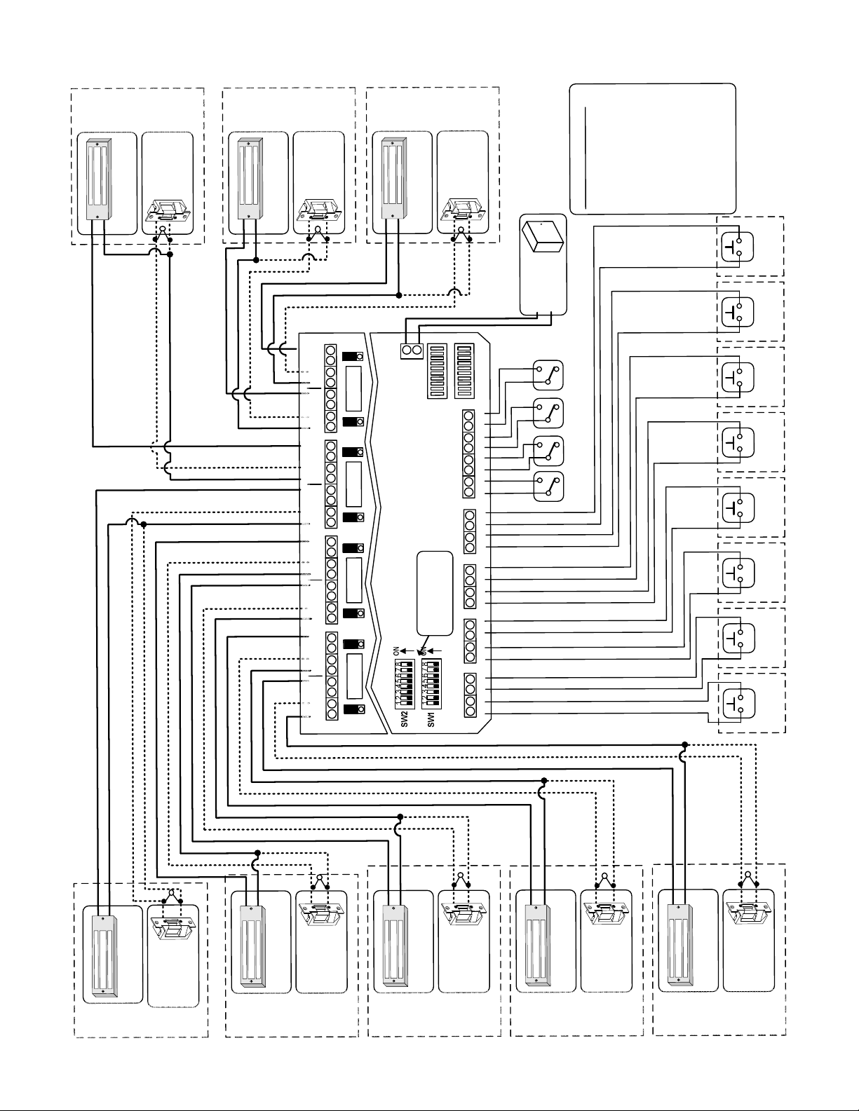
n
K
o
i
2
C
t
C
a
O
t
L
S
)
E
C
R
D
U
K
)
C
C
O
D
L
V
E
4
2
F
A
R
S
-
O
L
2
I
1
A
(
F
-
+
V
K
C
4
C
E
2
S
O
-
R
L
L
O
I
A
2
1
F
(
-
+
MOV
*
n
K
o
i
1
C
t
D
a
O
t
L
S
)
E
C
R
D
U
K
)
C
C
O
D
L
V
E
4
2
F
A
R
S
O
L
2
I
1
A
(
F
-
+
V
K
C
4
C
E
2
S
O
-
R
L
L
O
I
A
2
1
F
(
-
+
MOV
*
D
W
C
N
8
T
C
U
P
T
N
O
U
O
(-)
7
T
U
P
T
U
O
(-)
6
T
U
P
T
U
O
(-)
5
T
U
P
T
U
O
(-)
4
T
U
P
T
U
O
(-)
3
T
U
P
T
U
O
(-)
2
T
U
P
T
U
O
(-)
1
T
U
P
T
U
O
(-)
E
S
U
N
C
F
C
N
O
D
W
D
W
N
C
C
N
O
E
S
U
N
C
F
C
N
O
D
W
D
W
N
C
C
N
O
E
S
U
N
C
F
C
N
O
D
W
D
W
N
C
C
N
O
E
S
U
N
C
F
C
N
O
D
W
n
K
o
i
2
C
t
D
a
O
t
L
S
)
E
C
R
D
U
K
)
C
C
O
D
L
V
E
4
2
F
A
R
S
O
L
2
I
1
A
(
F
-
+
(-)
+
t
u
C
p
D
n
I
V
r
4
e
2
/
w
2
o
1
P
L
O
R
T
N
O
C
E
D
Y
A
O
L
M
E
R
E
L
G
N
I
S
DIP SWITCHES
V
K
C
4
C
E
2
O
S
-
R
L
L
O
I
A
2
1
F
(
0
-
+
MOV
*
4
E
C
3
E
C
2
E
C
1
E
C
2
D
C
1
D
C
2
C
C
1
C
C
2
Page 13, Step 1
Set as shown on
B
C
1
B
C
2
A
C
1
A
C
0
6
C
D
S
C
D
R
V
E
4
W
2
/
O
2
P
1
*MOV for Inductive Kickback protection. See Step 3 on Pg. 13
+
:
n
y
S
l
l
w
E
a
o
T
h
m
O
r
s
N
o
e
.
N
r
N
s
a
s
e
O
I
a
s
h
t
T
c
d
t
u
A
i
e
p
r
L
w
n
L
u
i
s
l
g
A
i
l
n
f
T
A
e
n
S
p
.
o
N
1
c
O
I
s
e
i
r
e
S
Y
L
P
P
U
S
-
Y
)
C
l
E
a
N
S
n
E
A
o
i
G
E
t
L
R
p
E
E
O
(
R
M
E
)
T
l
a
U
n
O
o
i
K
t
C
p
O
O
(
L
)
l
K
a
C
n
L
o
O
L
i
t
L
A
p
N
O
U
(
)
l
a
K
n
L
o
C
i
L
t
O
A
p
L
O
(
e
b
l
e
l
e
i
v
v
w
a
.
a
h
s
h
e
t
g
s
u
o
t
a
t
p
t
u
t
l
d
p
u
o
t
e
o
v
r
u
)
t
u
o
e
u
g
y
i
g
p
f
t
a
a
l
n
t
u
l
e
o
o
r
o
c
l
v
y
l
(
n
a
A
t
l
e
e
e
e
.
2
b
w
R
e
r
a
8
8
4
&
R
,
U
6
,
e
4
h
.
,
t
e
2
s
g
.
s
a
a
t
e
m
a
s
e
h
t
d
t
l
u
e
o
p
s
t
v
u
u
f
t
-
u
O
n
p
o
.
n
i
3
n
2
r
D
e
n
g
o
g
i
i
t
r
a
T
t
S
1
r
D
e
n
g
o
g
i
i
t
r
a
T
t
S
2
r
C
e
n
g
o
g
i
i
t
r
a
T
t
S
1
r
C
e
n
g
o
g
i
i
t
r
a
T
t
S
2
r
B
e
n
g
o
g
i
i
t
r
a
T
t
S
1
r
B
e
n
g
o
g
i
i
t
r
a
T
t
S
2
r
A
e
n
g
o
g
i
i
t
r
a
T
t
S
1
r
A
e
n
g
o
g
i
i
t
r
a
T
t
S
+
P:\INSTALLA
-
K
)
C
C
O
D
L
V
E
4
2
F
A
R
S
O
L
2
I
1
A
(
F
n
o
i
1
t
C
a
t
S
TION INST\P
+
K
C
O
L
)
E
C
R
D
U
V
K
C
4
C
E
2
S
O
-
R
L
L
O
I
A
2
1
F
(
wer Supplie
o
*
*
-
MOV
-
+
\INST-UR\IN
s
K
)
C
C
O
D
L
V
E
4
2
F
A
R
S
O
L
2
I
1
A
(
F
n
o
i
2
t
B
a
t
S
T-UR4-8.vsd
S
+
E
R
U
K
C
C
E
S
O
-
L
L
I
A
F
K
C
O
L
REV A1
-
)
C
D
V
4
2
R
O
2
1
(
MOV
+
11-14
-
K
)
C
C
O
D
L
V
E
4
2
F
A
R
S
O
L
2
I
1
A
(
F
n
o
i
t
a
t
S
Page 14
*
MOV
-
+
)
E
C
R
D
U
V
K
C
4
C
E
2
S
O
-
R
L
L
O
I
A
2
1
F
(
K
1
C
B
O
L
-
+
K
)
C
C
O
D
L
V
E
4
2
F
A
R
S
-
O
L
2
I
1
A
(
F
n
o
i
2
t
A
a
t
S
*
MOV
-
+
)
E
C
R
D
U
V
K
C
4
C
E
2
S
O
-
R
L
L
O
I
A
2
1
F
(
K
C
O
L
-
+
K
)
C
C
O
D
L
V
E
4
2
F
A
R
S
-
O
L
2
I
1
A
(
F
n
o
i
1
t
A
a
t
S
*
MOV
-
+
)
E
C
R
D
U
V
K
C
4
C
E
2
O
S
-
R
L
L
O
I
A
2
1
F
(
K
C
O
L
Page 15
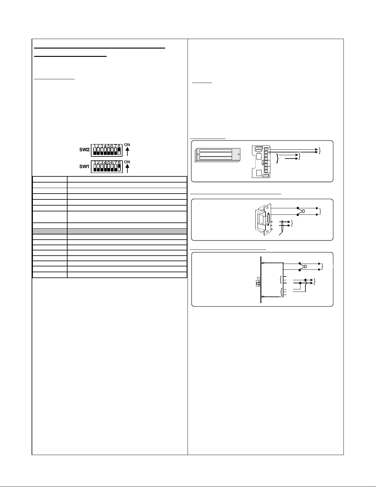
X. 2-Door Communicating Bath System
SW2-1 = OFF
SW2-2 = OFF
SW2-3 = OFF
SW2-4 = OFF
SW2-5 = OFF
SW2-6 = OFF
Setup (Single or Dual)
Follow the installation steps below before applying power to the UR4-8.
Standard Operation:
Refer to Page 4 – Section IX for method of operation.
Refer to the 2-Door Communicating Bath System wiring diagram on
Page 16.
It is assumed that the UR4-8 and locks will share the same power supply.
Step 1 – Set Dip Switches
The dip switch settings for a 2-Door Communicating Bath System must be
set as shown below. Adjust SW1-7 as required.
SW1 -1 = OFF
SW1 -2 = OFF
SW1 -3 = OFF
SW1 -4 = OFF
SW1 -5 = OFF
SW1 -6 = OFF
SW1 -7 = OFF
SW1 -8 = ON
{OFF = Single Com m Bath System;
ON = Dual Com m B ath System}
Step 4. Terminate the Lock Power and Lock
Monitoring Options
Select your specific lock type below. Follow the typical Communicating
Bath system wiring diagram. Be careful to observe lock voltage polarity.
*
WARNING!:
inductive kickback generated when power is removed from an inductive
load (e.g., electric strikes). Refer to the lock manufacturer's installation
manual or contact the manufacturer for kickback protection
recommendations.
NOTE: All lock monitoring options below (LBM, DPS, and/or REX) shown
wired so that the circuit is OPEN when the doors are CLOSED and
LATCHED.
Using EMLocks®:
Using Fail-safe Uni-FLEX™ Electric Strikes:
w/ Latch Bolt Monitoring (LBM)
NOTE: Mechanical locksets are
configured for “Storeroom”
function.
The UR board Relay Outputs must be protected against
3 4 5 6 7 8
NC
C
DPS
NO
EMLock® with DPS
(12 OR 24 VDC)
Fail-safe Electric Strike
NC
NO
LBM
C
MOV
To Lock
Monitoring
To Lock
Monitoring
*
Input
Input
LOCK
PWR
+
LOCK
PWR
-
SW2-7 = OFF
SW2-8 = ON
Step 2 – Configure the Relay Outputs to be Wet
(Voltage) or Dry.
Use the red WET/DRY Selection Jumpers to configure each output.
Refer to Page 2 of this instruction for selection procedure.
For a Single Communicating Bath System:
Outputs 1, 2, 3, & 4 are configured to be wet outputs.
Outputs 5, 6, 7, & 8 are configured as dry outputs.
For Dual Communicating Bath Systems:
All outputs are configured to be wet outputs.
The relay output voltage will be the same as the UR4-8 input voltage (12
or 24 VDC).
Step 3. Terminate the Activation and Emergency
Unlock Buttons
For each system, connect the (2) Emergency Unlock buttons and (1)
Activation button as shown on the Communicating Bath system wiring
diagram.
All button switches are wired Normally Open.
Lamp voltage is not polarity sensitive.
Using Fail-safe Selectric® Pro Locks:
MOV
*
+
LOCK
PWR
Fail-safe Electrified Mortise Lock
w/ Door Position Switch (DPS) &
Request-to-Exit Switch (REX)
REX
DPS
NC
C
NO
NC
C
NO
-
To Lock
Monitoring
Input
Step 6. Connect a 12 or 24VDC Power Source to the
UR4-8 Controller.
Before applying power, verify that all the connections are securely
terminated by gently pulling on each wire.
Terminate the voltage wiring to the Controller Power Input. Be careful to
observe polarity.
Verify that both doors are closed & apply power to the controller.
Step 7. UR4-8 Controller Startup and Operation
Verification.
Verify the polarity of the inputs by observing the Status Lights located on
the lower right of the controller.
With the system at rest, Status Lights A1, A2, B1, B2, & C1 should all be
turned off.
NOTE: All low voltage wiring shall be 18-gauge minimum. The minimum
lock power wire gauge shall be determined by the SDC wire gauge chart.
Test the standard operation of the Communicating Bath System as
described on Page 4.
Signal wire shall be 22-guage minimum.
P:\INSTALLATION INST\Power Supplies\INST-UR\INST-UR4-8.vsd REV A1 11-14 Page 15
Page 16
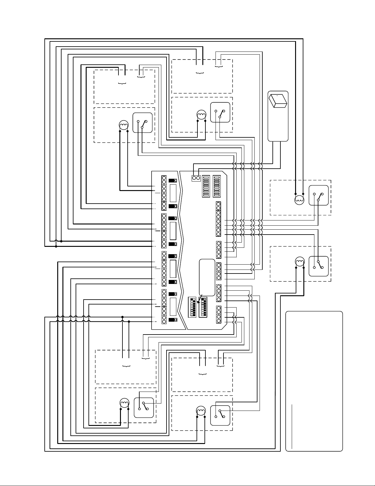
+
(-)
+
(-)
LOCK
Fail-safe Lock
CB402B
Emergency
POWER
(System B – Door #2)
L
Button
(System B – Door #2)
OUTPUT
FROM LOCK
MONITORING
NC
NO
C
N
C
C
N
O
OUTPUT 8
(-)
N
C
C
N
O
(-)
OUTPUT 7
N
C
C
N
O
OUTPUT 6
(-)
N
C
C
N
O
(-)
OUTPUT 5
N
C
C
N
O
OUTPUT 4
(-)
N
C
C
N
O
(-)
OUTPUT 3
N
C
C
N
O
OUTPUT 2
(-)
N
C
C
N
O
OUTPUT 1
(-)
Fail-safe Lock
CB402B
D
W
FUSE
D
W
D
W
FUSE
D
W
D
W
FUSE
D
W
D
W
FUSE
D
W
LOCK
POWER
(System B – Door #1)
L
Button
Emergency
(System B – Door #1)
(-)
+
12/24 VDC
Power Input
(Single or Dual System)
OUTPUT
FROM LOCK
MONITORING
Series
SDC 600
NC
NO
C
12/24 VDC
POWER
SUPPLY
-
+
NC
NO
L
Button
CB402A
Activation
(System B)
C E1 C E 2 C E3 C E4
C D1 C D2
CB402A
Activation
L
Button
(System A)
C
C
NC
NO
2-Door Communicating Bath
Page 15, Step 1
DIP SWITCHES
Set as shown on
7 8
7 8
1 2 3 45 6
1 2 3 45 6
SW1
SW2
C A1 C A2 C B1 C B2 C C1 C C2
+
(-)
LOCK
Fail-safe Lock
(System A – Door #1)
CB402B
Emergency
P:\INSTALLATION INST\Power Supplies\INST-UR\INST-UR4-8.vsd REV A1 11-14 Page 16
POWER
L
Button
(System A – Door #1)
OUTPUT
FROM LOCK
MONITORING
Fail-safe Lock
(System A – Door #2)
C
NC
NO
Button
CB402B
Emergency
+
(-)
LOCK
POWER
L
(System A – Door #2)
OUTPUT
FROM LOCK
MONITORING
C
NC
NO
INSTALLATION NOTES:
1. For a Single Comm. Bath System, terminate System “A” wiring
only. For Dual Comm. Bath Systems, terminate System “A” & “B”
wiring.
2. Refer to the lock’s installation instructions for the lock wiring
details.
3. For a single system, outputs 1- 4 are configured as wet (voltage)
outputs. For dual systems, all outputs are configured as wet (voltage)
outputs. Output voltage will be the same as the UR4-8 input voltage.
 Loading...