

Scytek electronic Precision 700 series Product Manual
PRODUCT MANUAL
PRECISION
770000 SSEERRIIEESS
VEHICLE SECURITY SYSTEM

LLiimmiitteedd LLiiffeettiimmee WWaarrrraannttyy
This vehicle security system is warranted to the original purchaser, to be free from defects in
material and workmanship. The manufacturer will repair or replace at its option, and free of
charge for the first twelve (12) months, any part that proves defective in material or workmanship
under normal installation, use, and service, provided the product is returned to the manufacturer
freight prepaid. After the first 12 month warranty period there will be a maximum service charge
of $25.00 per calendar year (if required) for repair and/or replacement of any defective parts.
A copy of the original purchase receipt must accompany any products returned for warranty
service. Warranty is limited to defective parts and/or replacement parts only and excludes any
incidental, and consequential damages connected therewith.
The manufacturer of this theft deterrent system makes no warranty against the theft of the vehicle
or its contents. This warranty is not to be construed as an insurance policy against loss.
WARRANTY OF INSTALLATION LABOR, REMOVALAND RE-INSTALLATION CHARGES ARE
NOT THE RESPONSIBILITY OF THE MANUFACTURER.

1. About Your System . . . . . . . . . . . . . . . . . . . . . . . . . . . . . . . . . . . . . . . . . . . . . . . . . . . . . .Page 1
2. 2-way LCD Remote Transmitters . . . . . . . . . . . . . . . . . . . . . . . . . . . . . . . . . . . . . . . . . . . . . . . . . . . . . . . . .Page 2
2-way LCD Remote Transmitter Description . . . . . . . . . . . . . . . . . . . . . . . . . . . . . . . . . . . . . . . . . . . .Page 2
Adding/Replacing 2-way LCD Transmitters . . . . . . . . . . . . . . . . . . . . . . . . . . . . . . . . . . . . . . . . . . . . .Page 2
Battery Replacement . . . . . . . . . . . . . . . . . . . . . . . . . . . . . . . . . . . . . . . . . . . . . . . . . . . . . . . . . . . .Page 3
Setting The Time . . . . . . . . . . . . . . . . . . . . . . . . . . . . . . . . . . . . . . . . . . . . . . . . . . . . . . . . . . . . . . .Page 3
Setting The Alarm Clock . . . . . . . . . . . . . . . . . . . . . . . . . . . . . . . . . . . . . . . . . . . . . . . . . . . . . . . . . .Page 3
Setting The Automatic Start or Auto Activate Function . . . . . . . . . . . . . . . . . . . . . . . . . . . . . . . . . . . .Page 3
LCD Backlight . . . . . . . . . . . . . . . . . . . . . . . . . . . . . . . . . . . . . . . . . . . . . . . . . . . . . . . . . . . . . . . . .Page 4
System Confirmation . . . . . . . . . . . . . . . . . . . . . . . . . . . . . . . . . . . . . . . . . . . . . . . . . . . . . . . . . . . .Page 4
Transmitter Programming . . . . . . . . . . . . . . . . . . . . . . . . . . . . . . . . . . . . . . . . . . . . . . . . . . . . . . . . .Page 4
LCD Confirmation . . . . . . . . . . . . . . . . . . . . . . . . . . . . . . . . . . . . . . . . . . . . . . . . . . . . . . . . . . . . . .Page 5
3. Remote Transmitters . . . . . . . . . . . . . . . . . . . . . . . . . . . . . . . . . . . . . . . . . . . . . . . . . . . . . . . . . . . . . . . . .Page 6
Remote Transmitter Description . . . . . . . . . . . . . . . . . . . . . . . . . . . . . . . . . . . . . . . . . . . . . . . . . . . .Page 6
Adding/Replacing Transmitters . . . . . . . . . . . . . . . . . . . . . . . . . . . . . . . . . . . . . . . . . . . . . . . . . . . . .Page 7
Two Car Operation . . . . . . . . . . . . . . . . . . . . . . . . . . . . . . . . . . . . . . . . . . . . . . . . . . . . . . . . . . . . . .Page 7
Battery Replacement . . . . . . . . . . . . . . . . . . . . . . . . . . . . . . . . . . . . . . . . . . . . . . . . . . . . . . . . . . . .Page 7
4. System Operation . . . . . . . . . . . . . . . . . . . . . . . . . . . . . . . . . . . . . . . . . . . . . . . . . . . . . . . . . . . . . . . . . . . .Page 8
Remote Arming . . . . . . . . . . . . . . . . . . . . . . . . . . . . . . . . . . . . . . . . . . . . . . . . . . . . . . . . . . . . . . . .Page 8
Remote Disarming . . . . . . . . . . . . . . . . . . . . . . . . . . . . . . . . . . . . . . . . . . . . . . . . . . . . . . . . . . . . . .Page 8
Tamper Alert . . . . . . . . . . . . . . . . . . . . . . . . . . . . . . . . . . . . . . . . . . . . . . . . . . . . . . . . . . . . . . . . . .Page 9
Silent Arming/Disarming . . . . . . . . . . . . . . . . . . . . . . . . . . . . . . . . . . . . . . . . . . . . . . . . . . . . . . . . . .Page 9
Passive Arming . . . . . . . . . . . . . . . . . . . . . . . . . . . . . . . . . . . . . . . . . . . . . . . . . . . . . . . . . . . . . . . .Page 9
Panic Mode . . . . . . . . . . . . . . . . . . . . . . . . . . . . . . . . . . . . . . . . . . . . . . . . . . . . . . . . . . . . . . . . . .Page 10
Emergency Override . . . . . . . . . . . . . . . . . . . . . . . . . . . . . . . . . . . . . . . . . . . . . . . . . . . . . . . . . . . .Page 10
Optional Coded Emergency Override . . . . . . . . . . . . . . . . . . . . . . . . . . . . . . . . . . . . . . . . . . . . . . . .Page 10
Automatic Rearming . . . . . . . . . . . . . . . . . . . . . . . . . . . . . . . . . . . . . . . . . . . . . . . . . . . . . . . . . . . .Page 11
Valet Mode . . . . . . . . . . . . . . . . . . . . . . . . . . . . . . . . . . . . . . . . . . . . . . . . . . . . . . . . . . . . . . . . . .Page 11
5. Extended Features . . . . . . . . . . . . . . . . . . . . . . . . . . . . . . . . . . . . . . . . . . . . . . . . . . . . . . . . . . . . . . . . . .Page 12
Ignition Controlled Door Locks . . . . . . . . . . . . . . . . . . . . . . . . . . . . . . . . . . . . . . . . . . . . . . . . . . . .Page 12
Dome Light Activation . . . . . . . . . . . . . . . . . . . . . . . . . . . . . . . . . . . . . . . . . . . . . . . . . . . . . . . . . .Page 12
Auxiliary Function Outputs . . . . . . . . . . . . . . . . . . . . . . . . . . . . . . . . . . . . . . . . . . . . . . . . . . . . . . .Page 12
Disarm with Auxiliary Function . . . . . . . . . . . . . . . . . . . . . . . . . . . . . . . . . . . . . . . . . . . . . . . . . . . .Page 12
Remote Sensor Disable . . . . . . . . . . . . . . . . . . . . . . . . . . . . . . . . . . . . . . . . . . . . . . . . . . . . . . . . . .Page 12
Anti-Carjacking Protection . . . . . . . . . . . . . . . . . . . . . . . . . . . . . . . . . . . . . . . . . . . . . . . . . . . . . . . .Page 12
6. System Installation . . . . . . . . . . . . . . . . . . . . . . . . . . . . . . . . . . . . . . . . . . . . . . . . . . . . . . . . . . . . . . . . . .Page 13
Mounting the Control unit . . . . . . . . . . . . . . . . . . . . . . . . . . . . . . . . . . . . . . . . . . . . . . . . . . . . . . . .Page 14
Mounting the Siren . . . . . . . . . . . . . . . . . . . . . . . . . . . . . . . . . . . . . . . . . . . . . . . . . . . . . . . . . . . .Page 14
Mounting the Shock Sensor . . . . . . . . . . . . . . . . . . . . . . . . . . . . . . . . . . . . . . . . . . . . . . . . . . . . . .Page 14
7. System Wiring . . . . . . . . . . . . . . . . . . . . . . . . . . . . . . . . . . . . . . . . . . . . . . . . . . . . . . . . . . . . . . . . . . . . .Page 15
14-Pin Main Harness . . . . . . . . . . . . . . . . . . . . . . . . . . . . . . . . . . . . . . . . . . . . . . . . . . . . . . . . . . .Page 15
3 Pin Door Lock Harness . . . . . . . . . . . . . . . . . . . . . . . . . . . . . . . . . . . . . . . . . . . . . . . . . . . . . . . .Page 15
Plug-in Connectors . . . . . . . . . . . . . . . . . . . . . . . . . . . . . . . . . . . . . . . . . . . . . . . . . . . . . . . . . . . . .Page 16
J
umper Settings
. . . . . . . . . . . . . . . . . . . . . . . . . . . . . . . . . . . . . . . . . . . . . . . . . . . . . . . . . . . . .Page 16
8. System Programming . . . . . . . . . . . . . . . . . . . . . . . . . . . . . . . . . . . . . . . . . . . . . . . . . . . . . . . . . . . . . . . .Page 17
Entering System Programming . . . . . . . . . . . . . . . . . . . . . . . . . . . . . . . . . . . . . . . . . . . . . . . . . . . .Page 17
Default Reset . . . . . . . . . . . . . . . . . . . . . . . . . . . . . . . . . . . . . . . . . . . . . . . . . . . . . . . . . . . . . . . . .Page 17
Programmable System Options . . . . . . . . . . . . . . . . . . . . . . . . . . . . . . . . . . . . . . . . . . . . . . . . . . . .Page 17
Branch Table . . . . . . . . . . . . . . . . . . . . . . . . . . . . . . . . . . . . . . . . . . . . . . . . . . . . . . . . . . . . . . . . .Page 19
9. Door Lock Diagrams . . . . . . . . . . . . . . . . . . . . . . . . . . . . . . . . . . . . . . . . . . . . . . . . . . . . . . . . . . . . . . . . . . .Page 20
10. Two Stage Door Lock Diagrams . . . . . . . . . . . . . . . . . . . . . . . . . . . . . . . . . . . . . . . . . . . . . . . . . . . . . . . . .Page 21
11. Technical Information . . . . . . . . . . . . . . . . . . . . . . . . . . . . . . . . . . . . . . . . . . . . . . . . . . . . . . . . . . . . . . . .Page 23
12. Wiring Diagram . . . . . . . . . . . . . . . . . . . . . . . . . . . . . . . . . . . . . . . . . . . . . . . . . . . . . . . . . . . . . . . . . . .Back Page
TTaabbllee ooff CCoonntteennttss


Congratulations on your purchase of this state-of-the-art vehicle security system from ScyTek
Electronics. With proper installation this system will provide superior protection and performance
for many years to come.
System Contents:
• Main Unit
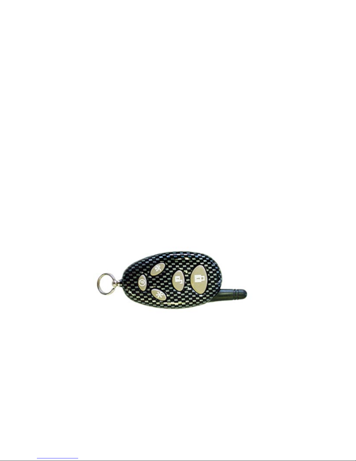
• Optional One 5-Button 2-Way LCD Remote Transmitter
• Two 5-Button Random Code Remote Transmitter
• Optional 2-Way Pager Transceiver Antenna
• High Output 6-tone Siren
• Dual Stage Shock Sensor
•
Status LED
• Coded Valet Switch
Options and Accessories
*
This ScyTek system includes several optional inputs and outputs allowing the creation of a
completely personalized security and convenience system by offering many optional features
such as:
*May require additional parts and/or labor, see store for details.
Precision 700 - Page 1
· Second Car Operation
· Remote Door Locking
· Two Stage Door Unlocking
· Starter Defeat
· Horn Honk
· Illuminated Entry
· Remote Window Control
· Remote Car Start
· Extended Range Antenna
· Power Trunk / Hatch Release
· Glass Breakage Sensor
· Radar Sensor
· Auxiliary Lighting Control
· Back-up Battery Siren
AAbboouutt YYoouurr SSyysstteemm
PLEASE NOTE:
Some of the features described in this manual may require additional parts and/or labor, and may not be included
as part of the standard installation of this unit. Additionally, many features of this security system have
selectable options that must be activated or programmed during the system’s installation. These items will be
identified in the following sections. Please discuss these features and any questions you may have regarding the
installation of this product with Your Authorized Dealer.
Page 2 - Precision 700
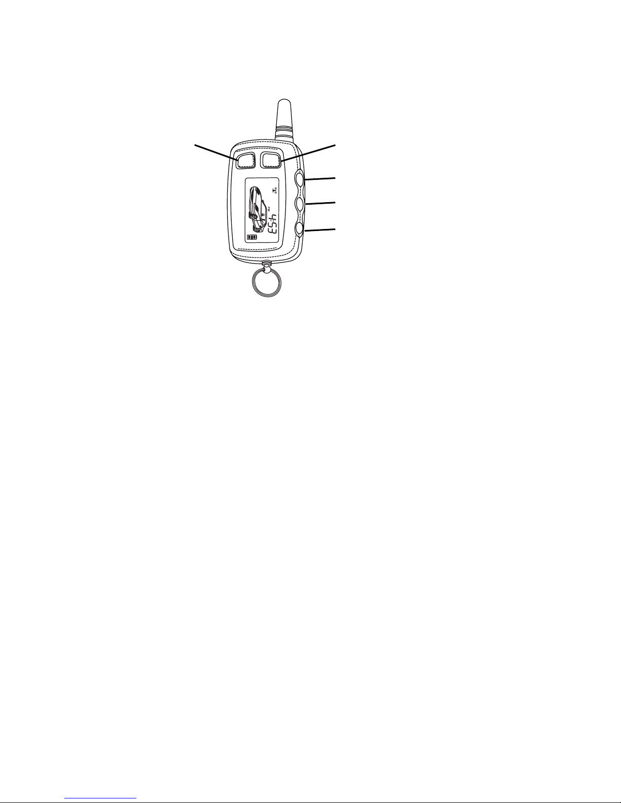
OPTIONAL - 2-way LCD Remote Transmitter Description
The Precision 700 2-way LCD remote transmitter is offering an increased range and confirmation of any
activated features.
Button 1
Arms and Disarms the system and when held for 2 seconds, activates the system’s Panic feature.
Button 1 also locks/unlocks the doors when the system is in Valet Mode.
Button 2
Activates the Auxiliary 2 output.
Button 3
Activates the Auxiliary 1 output normally used for trunk release (note trunk icon on button).
Button 4 Activates Passenger Unlock (System Disarmed Only).
Button 5
is the Confirmation and Programming button. Quickly pressing button 5 will activate the LCD
display’s backlighting for use in the dark. Pressing button 5 for 2 seconds activates the system’s
confirmation feature which will then display the current status of the system (armed, disarmed, engine
running, etc.).
Note: Up to 2 transmitters can be programmed to operate the system. To erase any previously
stored transmitter codes, be sure to program all 2 transmitter memory locations.
Adding/Replacing 2-way LCD Transmitters
When adding an optional 2-way LCD transmitter to the system, follow these steps:
1. Turn on the ignition key On, Off, On, Off, On, Off, and back On. (Key On 4 times)
· The siren will chirp 4 times.
2. Press and hold the Override switch for 5 seconds.
· The siren will chirp 4 times.
· The LED will illuminate.
3. Press Button 1 on the first transmitter.
· The siren will chirp once.
4. Turn off the ignition key.
5. Repeat steps 1-4 to add an additional 2-way transmitter.
Button 1 Button 2
Button 3
Button 4
Button 5

Precision 700 - Page 3
LCD Transmitter Battery Replacement
Your Galaxy Remote Transmitter uses a 1.5 volt AAA alkaline battery, which will require replacement in time.
Depending on the amount of use, the battery may last up to six months before it needs replacement. When
the battery needs replacing, the system’s operating range will decrease, the LCD display will show only one
of three bars in the battery icon, or the display and sounds may suddenly stop and start as the battery
voltage drops below minimum.
In order to change the battery, first slide the battery door locking pin to the side. Carefully slide the battery
cover downward until it is free. While replacing the battery make sure that the positive and negative
terminals are positioned correctly, then carefully reassemble the transmitter case.
Setting The Time
The LCD display is equipped with a 12-hour clock that in addition to displaying the time, offers an alarm
clock function as well as a remote activation timer.
To set the time:
1. Press and hold Buttons 2 and 3 for three seconds.
· The remote will beep two times and three bars will be shown indicating time set mode is entered.
2. Press Button 2 until the correct hour is displayed.
3. Press Button 3 until the desired minute is displayed. The button may be held down to scroll faster.
4. When the desired time is displayed, press Button 5 to store.
· The remote will play a melody to indicate the time has been set.
Setting The Alarm Clock
The alarm clock function can be set to play an alert melody at a specific time of day.
To set the alarm clock function:
1. Press and hold Buttons 2 and 3 until the remote beeps three times.
· The alarm clock bell and three bars will be shown indicating alarm clock set mode is entered.
2. Press Button 2 until the desired hour is displayed.
3. Press Button 3 until the desired minute is displayed. The button may be held down to scroll faster.
4. When the desired time is displayed, press Button 5 to store.
· The remote will play a melody to indicate the alarm clock has been set.
To disable the alarm clock function:
1. Press and hold Buttons 2 and 3 until the remote beeps three times.
· The alarm clock bell and three bars will be shown indicating alarm clock set mode is entered.
2. Press Button 1 to disable the alarm clock.
· The remote will play a melody to indicate the alarm clock has been disabled.
Setting The Automatic Start Or Auto Activate Function
The Automatic Start Function provides a timer that allows the vehicle to automatically remote start at a
preset time of day. For non-remote start equipped systems, this feature allows activation of an auxiliary
feature at a preset time of day.
To set the automatic start / auto activate function:
1. Press and hold Buttons 2 and 3 until the remote beeps four times.
· The fan and clock will be shown indicating automatic start mode is entered.
2. Press Button 2 until the desired hour is displayed.
3. Press Button 3 until the desired minute is displayed. The button may be held down to scroll faster.

Page 4 - Precision 700
4. When the desired time is displayed, press Button 5 to store.
· The remote will play a melody to indicate the alarm clock has been set.
To disable the automatic start / auto activate function:
1. Press and hold Buttons 2 and 3 until the remote beeps four times.
· The fan and clock will be shown indicating automatic start mode is entered.
2. Press Button 1 to disable the alarm clock.
· The remote will play a melody to indicate the alarm clock has been disabled.
LCD Backlight
Transmitter Button 5 is used for confirmation, transmitter programming, as well as activation of
the LCD backlighting for use in the dark. Press button 5 momentarily to activate the LCD
backlight.
System Confirmation
The 2-way transmitter's confirmation feature allows the current vehicle status to be displayed
at any time.
To display system status:
1. Press and hold Button 5 until the display shows CON.
· The transmitter will beep once.
2. Release Button 5.
· The transmitter will beep once.
· The icons representing current system status will be displayed on the LCD panel.
Transmitter Programming
Pressing and holding transmitter button 5 will scroll through several transmitter programmable
options that may or may not be available depending on the model of system installed- CHP,
SND, and PSV. The CHP or chirp function allows remote enabling or disabling of the vehicle
siren's confirmation chirps.
Note: This feature may not be available on all systems.
To turn the siren chirps on or off:
1. Press and hold Button 5 until the display shows CHP.
·The transmitter will beep twice.
2. Release Button 5.
· The transmitter will beep once.
· The LCD panel will show a siren if the chirps are enabled or "off" if the chirps are
disabled.
The SND or sound function allows disabling of the transmitter's confirmation tones.
To turn the transmitter confirmation tones on or off:
1. Press and hold Button 5 until the display shows SND.
· The transmitter will beep three times.
2. Release Button 5.
· The transmitter will beep once.
· The LCD panel will play a tone if the sounds are enabled or "off" will be displayed if the
chirps are disabled.
Precision 700 - Page 5
The PSV or passive function allows the passive arming mode to be enabled or with the
transmitter.
Note: This feature may not be available on all systems.
To enable or disable the passive arming mode:
1. Press and hold Button 5 until the display shows PSV.
· The transmitter will beep four times.
2. Release Button 5.
· The transmitter will beep once.
· The LCD panel will play a tone if the sounds are enabled or "off" will be displayed if the
chirps are disabled.
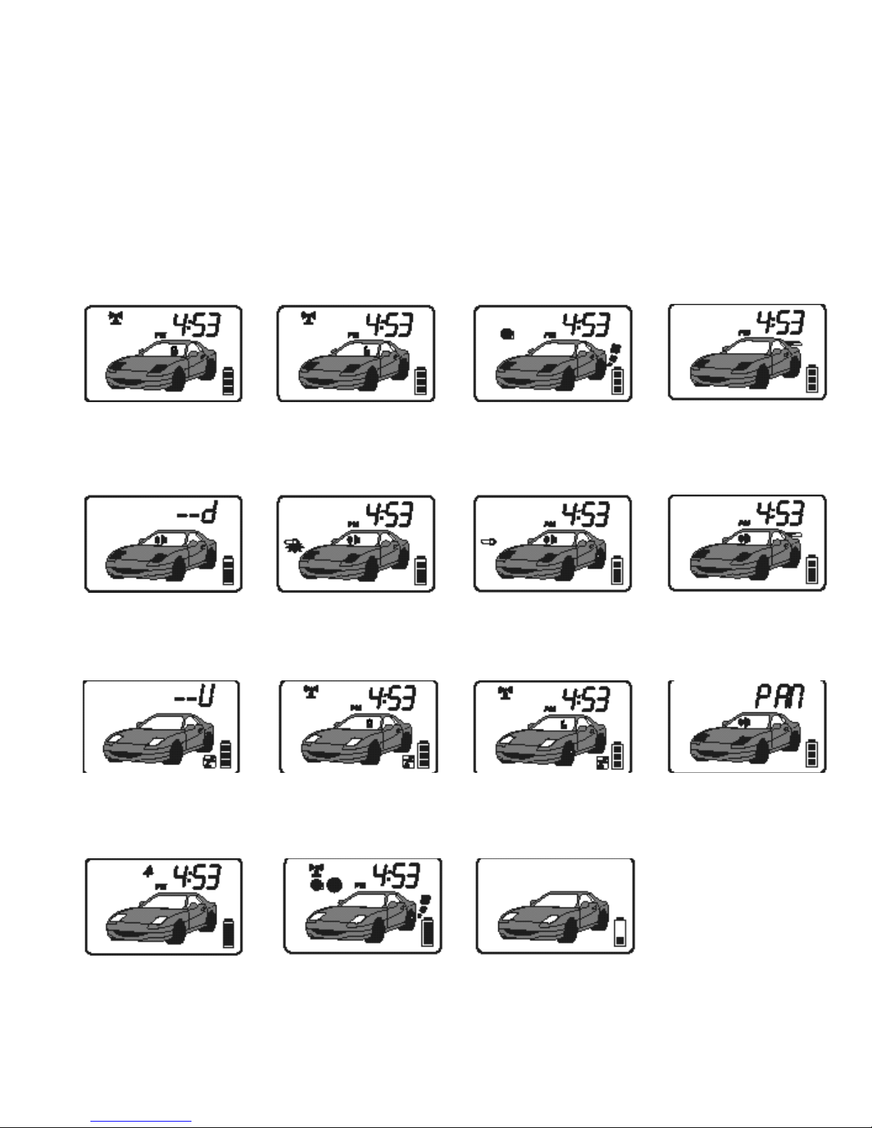
System Armed indicates
the doors are locked and
the alarm is on.
System Disarmed
indicates the doors are
unlocked and the alarm is
off.
Engine Run indicates
the engine is running on
remote start equipped
systems
Trunk Release indicates
the trunk or auxiliary
function has been
activated.
Door Open indicates the
door zone has been
triggered.
Shock Sensor indicates
the shock sensor has been
triggered.
Warn Away indicates
the warn away has been
triggered.
Trunk Open indicates
the trunk or hood zone
has been triggered.
Lock indicates the doors
are locked and the
system is in valet mode.
Valet Mode indicates the
system has been placed
into valet mode.
Unlock indicates the
doors are unlocked and
the system is in valet
mode
.
Panic indicates the panic
mode has been
triggered.
Alarm Clock indicates
the programmable timer
function has been set.
Auto Run indicates the
automatic remote start
timer has been set.
Battery Low indicates the
battery inside the
transmitter needs to be
replaced.
 Loading...