

Scytek electronic G777,G27,A777,A20 Product Manual

G777,G27
A777,A20
VEHICLE SECURITY SYSTEM
PRODUCT MANUAL

LLiimmiitteedd LLiiffeettiimmee WWaarrrraannttyy
This vehicle security system is warranted to the original purchaser, to be free from defects in
material and workmanship. The manufacturer will repair or replace at its option, and free of
charge for the first twelve (12) months, any part that proves defective in material or workmanship
under normal installation, use, and service, provided the product is returned to the manufacturer
freight prepaid. After the first 12 month of the warranty period there will be a maximum service
charge of $50.00 per calendar year (if required) for repair and/or replacement of any defective
parts.
A copy of the original purchase and installation receipt must accompany any products
returned for warranty service. Warranty is limited to defective parts and/or replacement parts
only and excludes any incidental, and consequential damages connected therewith.
The manufacturer of this theft deterrent system makes no warranty against the theft of the vehicle
or its contents. This warranty is not to be construed as an insurance policy against loss.
WARRANTY OF INSTALLATION LABOR, REMOVAL AND RE-INSTALLATION CHARGES ARE
NOT THE RESPONSIBILITY OF THE MANUFACTURER.
Note: This Warranty is voided if the product was not installed by an
Authorized ScyTek Dealer.

1. About Your System . . . . . . . . . . . . . . . . . . . . . . . . . . . . . . . . . . . . . . . . . . . . . . . . . . . . . . . . . . . .Page 1
2. 2-way LCD Remote Transmitters . . . . . . . . . . . . . . . . . . . . . . . . . . . . . . . . . . . . . . . . . . . . . . . . . . . . . . . . . . . . . .Page 2
2-way LCD Remote Transmitter Description . . . . . . . . . . . . . . . . . . . . . . . . . . . . . . . . . . . . . . . . . . . . . . . .Page 2
Adding/Replacing 2-way LCD Transmitters . . . . . . . . . . . . . . . . . . . . . . . . . . . . . . . . . . . . . . . . . . . . . . . . .Page 3
Battery Replacement . . . . . . . . . . . . . . . . . . . . . . . . . . . . . . . . . . . . . . . . . . . . . . . . . . . . . . . . . . . . . . . . . .Page 3
Setting The Time . . . . . . . . . . . . . . . . . . . . . . . . . . . . . . . . . . . . . . . . . . . . . . . . . . . . . . . . . . . . . . . . . . . . .Page 3
Setting The Alarm Clock . . . . . . . . . . . . . . . . . . . . . . . . . . . . . . . . . . . . . . . . . . . . . . . . . . . . . . . . . . . . . . .Page 3
LCD Backlight . . . . . . . . . . . . . . . . . . . . . . . . . . . . . . . . . . . . . . . . . . . . . . . . . . . . . . . . . . . . . . . . . . . . . . .Page 4
System Confirmation . . . . . . . . . . . . . . . . . . . . . . . . . . . . . . . . . . . . . . . . . . . . . . . . . . . . . . . . . . . . . . . . . .Page 4
Transmitter Programming . . . . . . . . . . . . . . . . . . . . . . . . . . . . . . . . . . . . . . . . . . . . . . . . . . . . . . . . . . . . . .Page 4
LCD Icon Description . . . . . . . . . . . . . . . . . . . . . . . . . . . . . . . . . . . . . . . . . . . . . . . . . . . . . . . . . . . . . . . . . .Page 5
3. Remote Transmitters . . . . . . . . . . . . . . . . . . . . . . . . . . . . . . . . . . . . . . . . . . . . . . . . . . . . . . . . . . . . . . . . . . . . . . . .Page 6
Remote Transmitter Description . . . . . . . . . . . . . . . . . . . . . . . . . . . . . . . . . . . . . . . . . . . . . . . . . . . . . . . . .Page 6
Adding/Replacing Transmitters . . . . . . . . . . . . . . . . . . . . . . . . . . . . . . . . . . . . . . . . . . . . . . . . . . . . . . . . . .Page 7
Two Car Operation . . . . . . . . . . . . . . . . . . . . . . . . . . . . . . . . . . . . . . . . . . . . . . . . . . . . . . . . . . . . . . . . . . . .Page 7
Battery Replacement . . . . . . . . . . . . . . . . . . . . . . . . . . . . . . . . . . . . . . . . . . . . . . . . . . . . . . . . . . . . . . . . . .Page 7
4. System Operation . . . . . . . . . . . . . . . . . . . . . . . . . . . . . . . . . . . . . . . . . . . . . . . . . . . . . . . . . . . . . . . . . . . . . . . . . .Page 8
Remote Arming . . . . . . . . . . . . . . . . . . . . . . . . . . . . . . . . . . . . . . . . . . . . . . . . . . . . . . . . . . . . . . . . . . . . . .Page 8
Remote Disarming . . . . . . . . . . . . . . . . . . . . . . . . . . . . . . . . . . . . . . . . . . . . . . . . . . . . . . . . . . . . . . . . . . . .Page 8
Tamper Alert . . . . . . . . . . . . . . . . . . . . . . . . . . . . . . . . . . . . . . . . . . . . . . . . . . . . . . . . . . . . . . . . . . . . . . . . .Page 9
Silent Arming/Disarming . . . . . . . . . . . . . . . . . . . . . . . . . . . . . . . . . . . . . . . . . . . . . . . . . . . . . . . . . . . . . . . .Page 9
Passive Arming . . . . . . . . . . . . . . . . . . . . . . . . . . . . . . . . . . . . . . . . . . . . . . . . . . . . . . . . . . . . . . . . . . . . . .Page 9
Panic Mode . . . . . . . . . . . . . . . . . . . . . . . . . . . . . . . . . . . . . . . . . . . . . . . . . . . . . . . . . . . . . . . . . . . . . . . .Page 10
Emergency Override . . . . . . . . . . . . . . . . . . . . . . . . . . . . . . . . . . . . . . . . . . . . . . . . . . . . . . . . . . . . . . . . .Page 10
Optional Coded Emergency Override . . . . . . . . . . . . . . . . . . . . . . . . . . . . . . . . . . . . . . . . . . . . . . . . . . . .Page 10
Automatic Rearming . . . . . . . . . . . . . . . . . . . . . . . . . . . . . . . . . . . . . . . . . . . . . . . . . . . . . . . . . . . . . . . . . .Page 11
Valet Mode . . . . . . . . . . . . . . . . . . . . . . . . . . . . . . . . . . . . . . . . . . . . . . . . . . . . . . . . . . . . . . . . . . . . . . . . .Page 11
Driver Calling . . . . . . . . . . . . . . . . . . . . . . . . . . . . . . . . . . . . . . . . . . . . . . . . . . . . . . . . . . . . . . . . . . . Page 11
5. Extended Features . . . . . . . . . . . . . . . . . . . . . . . . . . . . . . . . . . . . . . . . . . . . . . . . . . . . . . . . . . . . . . . . . . . . . . . .Page 12
Ignition Controlled Door Locks . . . . . . . . . . . . . . . . . . . . . . . . . . . . . . . . . . . . . . . . . . . . . . . . . . . . . . . . . .Page 12
Dome Light Activation . . . . . . . . . . . . . . . . . . . . . . . . . . . . . . . . . . . . . . . . . . . . . . . . . . . . . . . . . . . . . . . .Page 12
Auxiliary Function Outputs . . . . . . . . . . . . . . . . . . . . . . . . . . . . . . . . . . . . . . . . . . . . . . . . . . . . . . . . . . . . .Page 12
Disarm with Auxiliary Function . . . . . . . . . . . . . . . . . . . . . . . . . . . . . . . . . . . . . . . . . . . . . . . . . . . . . . . . . .Page 12
Remote Sensor Disable . . . . . . . . . . . . . . . . . . . . . . . . . . . . . . . . . . . . . . . . . . . . . . . . . . . . . . . . . . . . . . .Page 12
Anti-Carjacking Protection . . . . . . . . . . . . . . . . . . . . . . . . . . . . . . . . . . . . . . . . . . . . . . . . . . . . . . . . . . . . .Page 12
6. System Installation . . . . . . . . . . . . . . . . . . . . . . . . . . . . . . . . . . . . . . . . . . . . . . . . . . . . . . . . . . . . . . . . . . . . . . . . .Page 13
Mounting the Control unit . . . . . . . . . . . . . . . . . . . . . . . . . . . . . . . . . . . . . . . . . . . . . . . . . . . . . . . . . . . . . .Page 14
Mounting the Siren . . . . . . . . . . . . . . . . . . . . . . . . . . . . . . . . . . . . . . . . . . . . . . . . . . . . . . . . . . . . . . . . . . .Page 14
Mounting the Shock Sensor . . . . . . . . . . . . . . . . . . . . . . . . . . . . . . . . . . . . . . . . . . . . . . . . . . . . . . . . . . . .Page 14
7. System Wiring . . . . . . . . . . . . . . . . . . . . . . . . . . . . . . . . . . . . . . . . . . . . . . . . . . . . . . . . . . . . . . . . . . . . . . . . . . .Page 15
14-Pin Main Harness . . . . . . . . . . . . . . . . . . . . . . . . . . . . . . . . . . . . . . . . . . . . . . . . . . . . . . . . . . . . . . . . .Page 15
3 Pin Door Lock Harness . . . . . . . . . . . . . . . . . . . . . . . . . . . . . . . . . . . . . . . . . . . . . . . . . . . . . . . . . . . . . .Page 15
Plug-in Connectors . . . . . . . . . . . . . . . . . . . . . . . . . . . . . . . . . . . . . . . . . . . . . . . . . . . . . . . . . . . . . . . . . .Page 16
J
umper Settings
. . . . . . . . . . . . . . . . . . . . . . . . . . . . . . . . . . . . . . . . . . . . . . . . . . . . . . . . . . . . . . . . . . .Page 16
8. System Programming . . . . . . . . . . . . . . . . . . . . . . . . . . . . . . . . . . . . . . . . . . . . . . . . . . . . . . . . . . . . . . . . . . . . . .Page 17
Entering System Programming . . . . . . . . . . . . . . . . . . . . . . . . . . . . . . . . . . . . . . . . . . . . . . . . . . . . . . . . .Page 17
Default Reset . . . . . . . . . . . . . . . . . . . . . . . . . . . . . . . . . . . . . . . . . . . . . . . . . . . . . . . . . . . . . . . . . . . . . . .Page 17
Programmable System Options . . . . . . . . . . . . . . . . . . . . . . . . . . . . . . . . . . . . . . . . . . . . . . . . . . . . . . . . .Page 17
Branch Table . . . . . . . . . . . . . . . . . . . . . . . . . . . . . . . . . . . . . . . . . . . . . . . . . . . . . . . . . . . . . . . . . . . . . . .Page 19
9. Door Lock Diagrams . . . . . . . . . . . . . . . . . . . . . . . . . . . . . . . . . . . . . . . . . . . . . . . . . . . . . . . . . . . . . . . . . . . . . . . . . .Page 20
10. Two Stage Door Lock Diagrams . . . . . . . . . . . . . . . . . . . . . . . . . . . . . . . . . . . . . . . . . . . . . . . . . . . . . . . . . . . . . .Page 21
11. Technical Information . . . . . . . . . . . . . . . . . . . . . . . . . . . . . . . . . . . . . . . . . . . . . . . . . . . . . . . . . . . . . . . . . . . . . . .Page 23
TTaabbllee ooff CCoonntteennttss

Congratulations on your purchase of this state-of-the-art vehicle security system from ScyTek
Electronics. With proper installation this system will provide superior protection and performance
for many years to come.
System Contents:
• Main Unit
• One 2-Way LCD Remote Transmitter and one 1-Way Remote Transmitter, G777, A777
• Two 1-Way Remote Transmitter, G27, A20
• 2-Way Pager Transceiver Antenna, G777, A777
• 6-tone Siren
• Dual Stage Shock Sensor
• Status LED
• Coded Override/Valet Switch, G27, A20
• Coded Override/ Valet Switch /LED/ Call Button built into the antenna, G777, A777
Options and Accessories
*
This ScyTek system includes several optional inputs and outputs allowing the creation of a
completely personalized security and convenience system by offering many optional features
such as:
*May require additional parts and/or labor, see store for details.
G777,G27,A777,A20 - Page 1
. MobiLink Upgrade, Arm/disarm/locate with a
Smart phone or PC
· Second Car Operation
· Remote Door Locking
· Two Stage Door Unlocking
· Starter Defeat
· Horn Honk
· Illuminated Entry
· Remote Window Control
· Remote Car Start
· Power Trunk / Hatch Release
· Glass Breakage Sensor
· Radar Sensor
· Auxiliary Lighting Control
· Back-up Battery Siren
. Factory Alarm Upgrade using Factory Key Fob
AAbboouutt YYoouurr SSyysstteemm
PLEASE NOTE:
Some of the features described in this manual may require additional parts and/or labor, and may not be included
as part of the standard installation of this unit. Additionally, many features of this security system have
selectable options that must be activated or programmed during the system’s installation. These items will be
identified in the following sections. Please discuss these features and any questions you may have regarding the
installation of this product with Your Authorized Dealer.
Page 2 - G777,G27,A777,A20
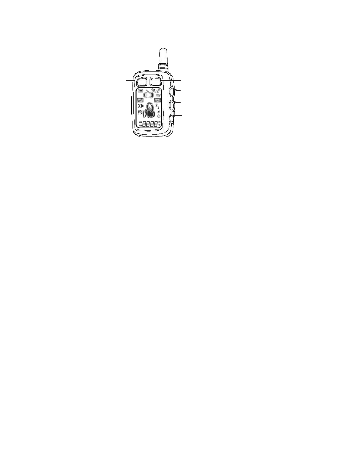
2-way LCD Remote Transmitter Description
Page 1
Button 1 Arms and Locks the system and when held for 5 seconds, activates the system’s Panic feature.
Button 1 also locks the doors when the system is in Valet Mode.
Button 2 Disarms and Unlocks the system. Pressing Button 2 again operates the Passenger Unlock feature
(if installed). Button 2 also unlocks the doors when the system is in Valet Mode.
Button 3 Activates the Auxiliary 1 output normally used for trunk release (note trunk icon on button).
Button 4 Activates the Remote Start feature.
Button 5 is the Confirmation, Programming and the Page Shift button. Quickly pressing button 5 will activate
the Page 2 function. Pressing button 5 for 2 seconds activates the system’s confirmation feature which will
then display the current status of the system (armed, disarmed, engine running, etc.).
Page 2
Button 1 Silently Arms/Locks the system.
Button 2 Silently Disarms/Unlocks the system.
Button 3 Activates the Auxiliary 2 output.
Button 4 Aux 3 or Factory Rearm output.
Button 5 Not Implemented. Page 3 & 4 are used as Page 1 & 2 for second car operation
LCD Transmitter Battery Replacement
Your Pager Remote Transmitter uses a 1.5 volt AAA alkaline battery, which will require replacement in time.
Depending on the amount of use, the battery may last up to 3 months before it needs replacement. When
the battery needs replacing, the system’s operating range will decrease, the LCD display will show only one
of three bars in the battery icon, or the display and sounds may suddenly stop and start as the battery
voltage drops below minimum.
In order to change the battery, first slide the battery door locking pin to the side. Carefully slide the battery
cover downward until it is free. While replacing the battery make sure that the positive and negative
terminals are positioned correctly, then carefully reassemble the transmitter case.
Button 1 Button 2
Button 3
Button 4
Button 5

G777,G27,A777,A20 - Page 3
Setting The Time
The LCD display is equipped with a 12-hour clock
Set the time:
1. Press and hold Buttons 2 and 3 for three seconds.
· The remote will beep two times and three bars will be shown indicating time set mode is entered.
2. Press and release Button 2 until the correct hour is displayed. (hold button to scroll).
3. Press and release Button 3 until the desired minute is displayed. (hold button to scroll).
4. When the desired time is displayed, press Button 5 to store.
· The remote will beep 3 times to indicate the time has been set.
Setting the control unit internal Auto Daily Start time
The Autostart function is set to a time of a day.
Set the unit Autostart clock function:
1. Press and hold Buttons 2 and 3 until the remote beeps two times.
·”Daily Start” icon will turn ON .
2. Press Button 2 until the desired hour is displayed.
3. Press Button 3 until the desired minute is displayed. The button may be held down to scroll faster.
4. When the desired time is displayed, press Button 1 to send to the daily start time to the control
unit.
· The remote will send and receive confirmation, the responce will display the daily start time
set in the unit.
Setting the pager Auto Daily Start Function ( transmitter must be within 1500ft to reliably
start)
The Daily Start Function provides a timer that allows the vehicle to automatically remote start at a preset
time of day , everyday until the feature is turned off.
Set the pager Autostart clock function:
1. Press and hold Buttons 2 and 3 until the remote beeps three times.
·”Alarm On ” icon wil turn ON .
2. Press Button 2 until the desired hour is displayed.
3. Press Button 3 until the desired minute is displayed. The button may be held down to scroll faster.
4. When the desired time is displayed;
press Button 5 to turn ON the daily start time
press Button 1 to turn OFF the daily start time

Page 4 - G777,G27,A777,A20
Power Save Mode
Power save mode disables automatic pager operations, alarm and starter status must be checked manually using button
5 for confirmation.
1. Press and hold Buttons 2 and 3 until the remote beeps six times.
· “PS” is shown indicating Power Save set/reset mode is entered.
2. Press Button 1 to toggle Power Save On/Off.
· The remote will display On or Off indicating the current status of the pager.
Pager power save mode status is indicated bellow
LCD Backlight
Transmitter Button 5 is used for confirmation, transmitter programming, as well as activation of the LCD
backlighting for use in the dark. Press and release button 5 momentarily to activate the LCD backlight.
System Confirmation
The 2-way transmitter's confirmation feature allows the current vehicle status to be displayed at any time.
To display system status:
1. Press and hold Button 5 until the display shows CON.
· The transmitter will beep once.
2. Release Button 5.
· The transmitter will beep once.
· The LCD panel will display the current system status.
Programmable Functions using the LCD Transmitter
Pressing and holding transmitter button 5 will scroll through several transmitter programmable options -
DEG, AUTO, SPCL, SSCL, C St, H St, A St, Snd .
DEG Check the temperature inside the vehicle
1. Press and hold Button 5 until the display shows DEG
·The transmitter will beep twice.
2. Release Button 5.
· The transmitter will beep four times.
· The LCD panel will display the temperature inside the vehicle
Normal
Mode
Power Save
Mode

G777,G27,A777,A20 - Page 5
AUTO display starter autostart enabled features.
1. Press and hold Button 5 until the display shows AUTO.
The transmitter will beep three times.
2. Release Button 5.
The LCD panel will display what starter auto start features are enabled.
SPCL Program the pager time of a day clock from the internal Remote Starter clock, the remote starter
sends its time to the pager.
1. Press and hold Button 5 until the display shows SPCL.
The transmitter will beep four times.
2. Release Button 5.
The pager will display the new time.
SSCL Program the remote starter time of a day clock from the pager
1. Press and hold Button 5 until the display shows SPCL.
The transmitter will beep five times.
2. Release Button 5.
The pager will display confirmation that the starter clock is sync.
C St Auto Start Cold Temperature Activation Mode.
1. Press and hold Button 5 until the display shows C St.
The transmitter will beep 6 times.
2. Release Button 5.
The transmitter will beep once.
The LCD panel will show Auto Start Cold Temperature setting.
3. Press and hold Button 5 until the display shows CON.
4. Release Button 5.
The transmitter will beep once.
The LCD panel will show "ON" indicating that Auto Start Cold Temperature Activation
Mode is enabled.
H St Auto Start Hot Temperature Activation Mode.
1. Press and hold Button 5 until the display shows H St.
The transmitter will beep 7 times.
2. Release Button 5.
The transmitter will beep once.
The LCD panel will show Auto Start Hot Temperature setting.
3. Press and hold Button 5 until the display shows CON.
4. Release Button 5.
The transmitter will beep once.
The LCD panel will show "ON" indicating that Auto Start Hot Temperature Activation
Mode is enabled
A St Auto Start Daily Activation Mode.
1. Press and hold Button 5 until the display shows A St.
The transmitter will beep 8 times.
2. Release Button 5.
The transmitter will beep once.
The LCD panel will show Daily Auto Start time setting.
3. Press and hold Button 5 until the display shows CON.
4. Release Button 5.
The transmitter will beep once.
The LCD panel will show "ON" indicating that Daily Auto Start Activation
Mode is enabled
SND sound function selects the transmitter's confirmation mode - Tone or Vibration mode.
Set the transmitter confirmation tones ON or OFF:
1. Press and hold Button 5 until the display shows SND.
The transmitter will beep 9 times.
2. Release Button 5.
The transmitter will beep once.
The LCD transmitter will beep 5 times and display “on” if the sounds are enabled or vibrate and
display "off" for the Remote to vibrate.
Page 6 - G777,G27,A777,A20
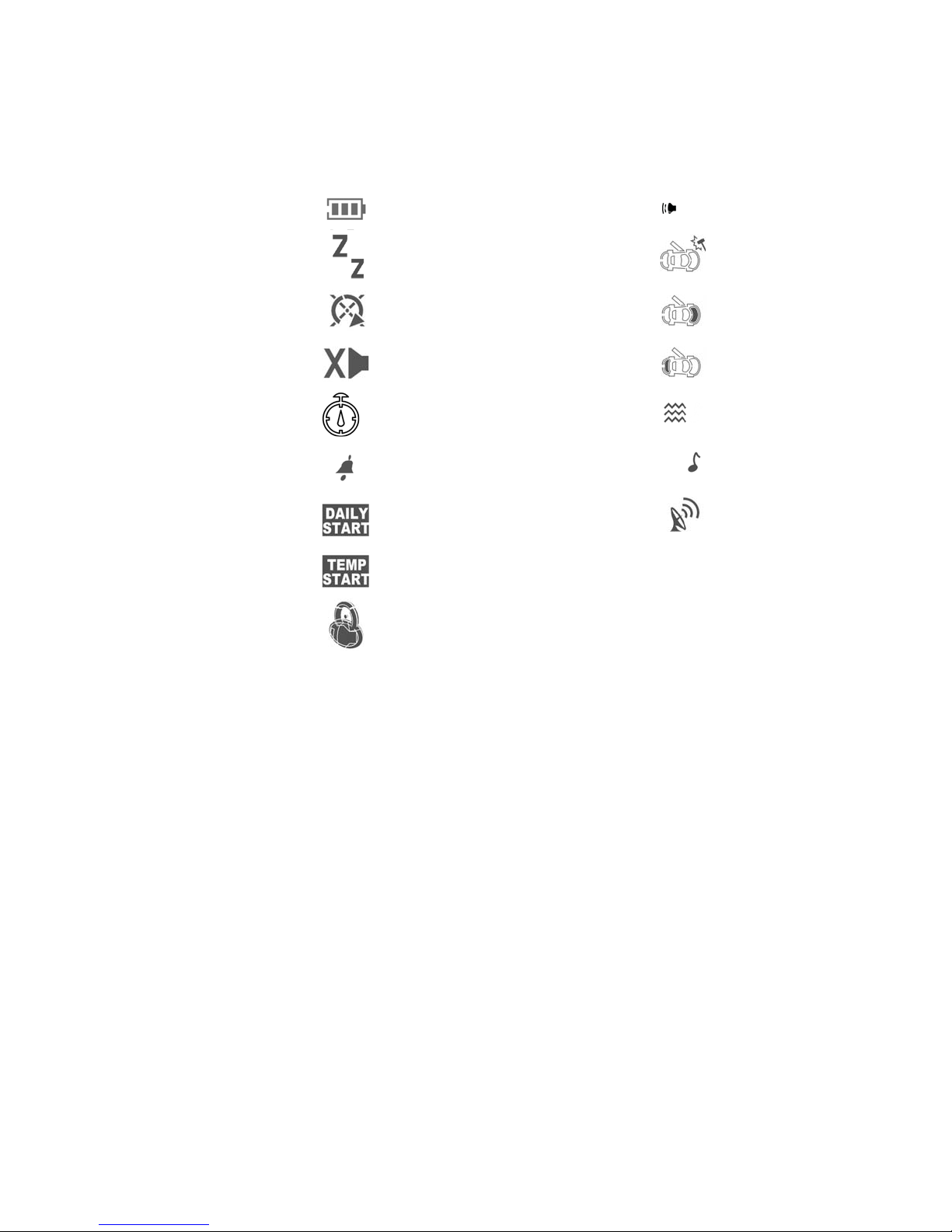
Pager Icon Description
Battery Status
Valet
Starter Status
Chirp Disable
Timer Start Enabled
Alarm Clock
Daily Start Enabled
Temperature Start Enabled
Lock/Unlock Status
Siren On
Vibration SensorTriggered
Hood Sensor Triggered
Trunk Sensor Triggered
Vibration On/Sound Off
Sound On/Vibration Off
Transmit
Adding/Replacing 2-way LCD Transmitters
(2 LCD remotes maximum)
When adding an optional 2-way LCD transmitter to the system, follow these steps:
1. Turn on the ignition key On, Off, On, Off, On, Off, and back On. (Key On 4 times)
· The siren will chirp 4 times.
2. Press and hold the Override switch for 5 seconds.
· The siren will chirp 4 times.
· The LED will illuminate.
3. Press Button 1 on the first transmitter, then on the second transmitter.
· The siren will chirp once for each transmitter learned.
4. Turn off the ignition key.
5. The siren will chirp 3 times to indicate the system has exited programming mode.
 Loading...