

Scytek electronic 5100RS User Manual

GALAXY 5100RS
SERIES
VEHICLE SECURITY SYSTEM
WITH REMOTE START
WWITH SEPERAATE LOCK/UNLOCK BUTTONS
PRODUCT MANUAL

Limited Lifetime Warranty
This vehicle security system is warranted to the original purchaser, to be free from defects in
material and workmanship. The manufacturer will repair or replace at its option, and free of
charge for the first twelve (12) months, any part that proves defective in material or workmanship
under normal installation, use, and service, provided the product is returned to the manufacturer
freight prepaid. After the first 12 month warranty period there will be a maximum service charge
of $25.00 per calendar year (if required) for repair and/or replacement of any defective parts.
A copy of the original purchase and installation receipt must accompany any products
returned for warranty service. Warranty is limited to defective parts and/or replacement parts
only and excludes any incidental, and consequential damages connected therewith.
The manufacturer of this theft deterrent system makes no warranty against the theft of the vehicle
or its contents. This warranty is not to be construed as an insurance policy against loss.
WARRANTY OF INSTALLATION LABOR, REMOVAL AND RE-INSTALLATION CHARGES ARE
NOT THE RESPONSIBILITY OF THE MANUFACTURER.
Note: This Warranty is voided if the product was not installed by an
Authorized ScyTek Dealer.

1. About Your System . . . . . . . . . . . . . . . . . . . . . . . . . . . . . . . . . . . . . . . . . . . . . . . . . . . . . . . . . . . . . . . .Page 1
2. Remote Transmitters . . . . . . . . . . . . . . . . . . . . . . . . . . . . . . . . . . . . . . . . . . . . . . . . . . . . . . . . . . . . . . .Page 2
2-WAY COLOR LCD REMOTE TRANSMITTER DESCRIPTION
. . . . . . . . . . . . . . . . . . . . . . . . . . . . . . . . . .Page 2
PAGER PARAMETERS SETTING . . . . . . . . . . . . . . . . . . . . . . . . . . . . . . . . . . . . . . . . . . . . . . . . . .Page 3
Set System Parameters
. . . . . . . . . . . . . . . . . . . . . . . . . . . . . . . . . . . . . . . . . . . . . . . . . . . . . . . . .Page 5
Recall Alarm History
. . . . . . . . . . . . . . . . . . . . . . . . . . . . . . . . . . . . . . . . . . . . . . . . . . . . . . . . . . .Page 7
Programmable Functions using the Color Remote . . . . . . . . . . . . . . . . . . . . . . . . . . . . . . . . . . . . .Page 8
ADDITIONAL FUNCTION
. . . . . . . . . . . . . . . . . . . . . . . . . . . . . . . . . . . . . . . . . . . . . . . . . . . . . . . .Page 9
ICONS
. . . . . . . . . . . . . . . . . . . . . . . . . . . . . . . . . . . . . . . . . . . . . . . . . . . . . . . . . . . . . . . . . . . .Page 9
Pager Status Display . . . . . . . . . . . . . . . . . . . . . . . . . . . . . . . . . . . . . . . . . . . . . . . . . . . . . . . . .Page 10
Remote Transmitter Description . . . . . . . . . . . . . . . . . . . . . . . . . . . . . . . . . . . . . . . . . . . . . . . . .Page 11
Adding/Replacing Transmitters . . . . . . . . . . . . . . . . . . . . . . . . . . . . . . . . . . . . . . . . . . . . . . . . . .Page 12
Two Car Operation . . . . . . . . . . . . . . . . . . . . . . . . . . . . . . . . . . . . . . . . . . . . . . . . . . . . . . . . . .Page 12
Battery Replacement . . . . . . . . . . . . . . . . . . . . . . . . . . . . . . . . . . . . . . . . . . . . . . . . . . . . . . . . .Page 12
2-way LCD Remote Transmitter Description . . . . . . . . . . . . . . . . . . . . . . . . . . . . . . . . . . . . . . . . .Page 13
Adding/Replacing 2-way Transmitters, Programable features and descriptions. . . . . . . . . . . . .Page 13-17
LCD Transmitter Battery Replacement . . . . . . . . . . . . . . . . . . . . . . . . . . . . . . . . . . . . . . . . . . . .Page 13
3. System Operation . . . . . . . . . . . . . . . . . . . . . . . . . . . . . . . . . . . . . . . . . . . . . . . . . . . . . . . . . . . . . . . .Page 18
Remote Arming*/Locking . . . . . . . . . . . . . . . . . . . . . . . . . . . . . . . . . . . . . . . . . . . . . . . . . . . . .Page 18
Remote Disarming*/Unlocking . . . . . . . . . . . . . . . . . . . . . . . . . . . . . . . . . . . . . . . . . . . . . . . . . .Page 18
Tamper Alert* . . . . . . . . . . . . . . . . . . . . . . . . . . . . . . . . . . . . . . . . . . . . . . . . . . . . . . . . . . . . .Page 19
Silent Arming*/Locking -Disarming*/Unlocking . . . . . . . . . . . . . . . . . . . . . . . . . . . . . . . . . . . . . .Page 19
Passive Arming* . . . . . . . . . . . . . . . . . . . . . . . . . . . . . . . . . . . . . . . . . . . . . . . . . . . . . . . . . . . .Page 19
Panic Mode . . . . . . . . . . . . . . . . . . . . . . . . . . . . . . . . . . . . . . . . . . . . . . . . . . . . . . . . . . . . . . .Page 20
Emergency Override* . . . . . . . . . . . . . . . . . . . . . . . . . . . . . . . . . . . . . . . . . . . . . . . . . . . . . . . .Page 20
Optional Coded Emergency Override* . . . . . . . . . . . . . . . . . . . . . . . . . . . . . . . . . . . . . . . . . . . .Page 20
Automatic Rearming* . . . . . . . . . . . . . . . . . . . . . . . . . . . . . . . . . . . . . . . . . . . . . . . . . . . . . . . .Page 21
Valet Mode/ Driver Calling Feature . . . . . . . . . . . . . . . . . . . . . . . . . . . . . . . . . . . . . . . . . . . . . . .Page 21
4. Remote Start Features . . . . . . . . . . . . . . . . . . . . . . . . . . . . . . . . . . . . . . . . . . . . . . . . . . . . . . . . . . . .Page 22
Remote Starting . . . . . . . . . . . . . . . . . . . . . . . . . . . . . . . . . . . . . . . . . . . . . . . . . . . . . . . . . . . .Page 22
Shut Down . . . . . . . . . . . . . . . . . . . . . . . . . . . . . . . . . . . . . . . . . . . . . . . . . . . . . . . . . . . . . . . .Page 22
Quick Stop . . . . . . . . . . . . . . . . . . . . . . . . . . . . . . . . . . . . . . . . . . . . . . . . . . . . . . . . . . . . . . . .Page 22
Automatic Start Mode . . . . . . . . . . . . . . . . . . . . . . . . . . . . . . . . . . . . . . . . . . . . . . . . . . . . . . . .Page 23
Turbo Timer Feature . . . . . . . . . . . . . . . . . . . . . . . . . . . . . . . . . . . . . . . . . . . . . . . . . . . . . . . . .Page 23
Manual Transmission Remote Starting . . . . . . . . . . . . . . . . . . . . . . . . . . . . . . . . . . . . . . . . . . . Page 24
5. Extended Features . . . . . . . . . . . . . . . . . . . . . . . . . . . . . . . . . . . . . . . . . . . . . . . . . . . . . . . . . . . . . . .Page 25
Ignition Door Locking . . . . . . . . . . . . . . . . . . . . . . . . . . . . . . . . . . . . . . . . . . . . . . . . . . . . . . . . .Page 25
Ignition Door Unlocking . . . . . . . . . . . . . . . . . . . . . . . . . . . . . . . . . . . . . . . . . . . . . . . . . . . . . .Page 25
Dome Light Activation . . . . . . . . . . . . . . . . . . . . . . . . . . . . . . . . . . . . . . . . . . . . . . . . . . . . . . . .Page 25
Auxiliary Function Outputs . . . . . . . . . . . . . . . . . . . . . . . . . . . . . . . . . . . . . . . . . . . . . . . . . . . . .Page 25
Disarm with Auxiliary Function* . . . . . . . . . . . . . . . . . . . . . . . . . . . . . . . . . . . . . . . . . . . . . . . . .Page 25
Remote Sensor Disable* . . . . . . . . . . . . . . . . . . . . . . . . . . . . . . . . . . . . . . . . . . . . . . . . . . . . . .Page 25
6. System Installation . . . . . . . . . . . . . . . . . . . . . . . . . . . . . . . . . . . . . . . . . . . . . . . . . . . . . . . . . . . . . . .Page 26
Mounting the Control unit . . . . . . . . . . . . . . . . . . . . . . . . . . . . . . . . . . . . . . . . . . . . . . . . . . . . .Page 27
Mounting the Siren* . . . . . . . . . . . . . . . . . . . . . . . . . . . . . . . . . . . . . . . . . . . . . . . . . . . . . . . . .Page 27
Mounting the Shock Sensor* . . . . . . . . . . . . . . . . . . . . . . . . . . . . . . . . . . . . . . . . . . . . . . . . . . .Page 27
7. System Wiring . . . . . . . . . . . . . . . . . . . . . . . . . . . . . . . . . . . . . . . . . . . . . . . . . . . . . . . . . . . . . . . . . .Page 27
6-Pin Starter Harness . . . . . . . . . . . . . . . . . . . . . . . . . . . . . . . . . . . . . . . . . . . . . . . . . . . . . . . .Page 28
20-Pin Main Harness . . . . . . . . . . . . . . . . . . . . . . . . . . . . . . . . . . . . . . . . . . . . . . . . . . . . . . . . .Page 28
Plug-in Connectors . . . . . . . . . . . . . . . . . . . . . . . . . . . . . . . . . . . . . . . . . . . . . . . . . . . . . . . . . .Page 29
8. Jumper Settings . . . . . . . . . . . . . . . . . . . . . . . . . . . . . . . . . . . . . . . . . . . . . . . . . . . . . . . . . . . . . . . . .Page 30
Jumper Selection . . . . . . . . . . . . . . . . . . . . . . . . . . . . . . . . . . . . . . . . . . . . . . . . . . . . . . . . . . .Page 30
9. System Programming . . . . . . . . . . . . . . . . . . . . . . . . . . . . . . . . . . . . . . . . . . . . . . . . . . . . . . . . . . . . .Page 31
Entering System Programming . . . . . . . . . . . . . . . . . . . . . . . . . . . . . . . . . . . . . . . . . . . . . . . . . .Page 31
Default Reset . . . . . . . . . . . . . . . . . . . . . . . . . . . . . . . . . . . . . . . . . . . . . . . . . . . . . . . . . . . . . .Page 31
Programmable System Options . . . . . . . . . . . . . . . . . . . . . . . . . . . . . . . . . . . . . . . . . . . . . . . . .Page 31
10. Relay Diagrams . . . . . . . . . . . . . . . . . . . . . . . . . . . . . . . . . . . . . . . . . . . . . . . . . . . . . . . . . . . . . . . . .Page 35
11. Door Lock Diagrams . . . . . . . . . . . . . . . . . . . . . . . . . . . . . . . . . . . . . . . . . . . . . . . . . . . . . . . . . . . . . .Page 38
12. Two Stage Door Lock Diagrams . . . . . . . . . . . . . . . . . . . . . . . . . . . . . . . . . . . . . . . . . . . . . . . . . . . .Page 38
13. Technical Information . . . . . . . . . . . . . . . . . . . . . . . . . . . . . . . . . . . . . . . . . . . . . . . . . . . . . . . . . . . . .Page 39
14. System Diagnostics . . . . . . . . . . . . . . . . . . . . . . . . . . . . . . . . . . . . . . . . . . . . . . . . . . . . . . . . . . . . . . .Page 40
15. Wiring Diagram . . . . . . . . . . . . . . . . . . . . . . . . . . . . . . . . . . . . . . . . . . . . . . . . . . . . . . . . . . . . . . . .Back Page
Table of Contents


The ScyTek Galaxy 5100RS Series is a
Combination Vehicle Security and Remote Starting System
featuring a built-in "ScyNet Network Port" that allows direct connection of optional accessory modules and
a PC interface offering expanded system operation. With proper installation this system will provide
superior protection and performance for many years to come.
The Galaxy’s 5100RS Series built-in remote starter is designed to offer maximum convenience by remote
starting your vehicle’s engine, turning on the heater/air conditioner, and then running for a pre-determined
time to provide a comfortable environment once you enter your vehicle.
To ensure the safety and security of the system while it is remote started, the Galaxy 5100RS Series
employs several safeguards. In the event the alarm is triggered while the engine is remotely running, the
remote start will immediately shutdown to prevent unauthorized users from attempting to drive the vehicle.
The system is equipped with a hood pin input to prevent access to the engine compartment while the
vehicle is remotely running. The Valet Mode prevents the remote start feature from operating in the event
the vehicle is to be serviced. Finally, the brake pedal also acts as a safety by shutting down the remote
start when pressed.
System Contents:
• Main Unit with built-in ScyNet Network Interface Port
• One 5-Button 2-Way LCD Remote and One 1-Way 5-Button Remote Transmitter(
RS-2W models
)
•
Two 5-Button Random Code Remote Transmitters (
RS & SP models
)
• High Output 6-tone Siren
• Dual Stage Shock Sensor
•
Status LED/ Coded Emergency Override/ Valet Switch/ Call button built into the antenna (See Page 30)
Optional ScyNet Network Interface Accessories:
• ScyNet Network Interface Software
Options and Convenience Features
**
This ScyTek system includes several optional inputs and outputs allowing the creation of a completely
personalized security and convenience system by offering many optional features such as:
**May require additional parts and/or labor, see store for details.
· Second Car Operation
· Keyless Entry
· Two Stage Door Unlocking
· Starter Defeat
· Horn Honk
· Illuminated Entry
· Turbo Timer
· Remote Window Control
· Power Trunk / Hatch Release
· Glass Breakage Sensor
· Radar Sensor
· Remote Head Lamp Control
· Back-up Battery Siren
About Your System
Some of the features described in this manual may require additional parts and/or labor, and may not be
included as part of the standard installation of this unit. Additionally, many features of these systems
have selectable options that must be activated or programmed during the system’s installation. These
items will be identified in the following sections. Please discuss these features and any questions you
may have regarding the installation of this product with Your Authorized Dealer.
Galaxy 5100RS - Page 1
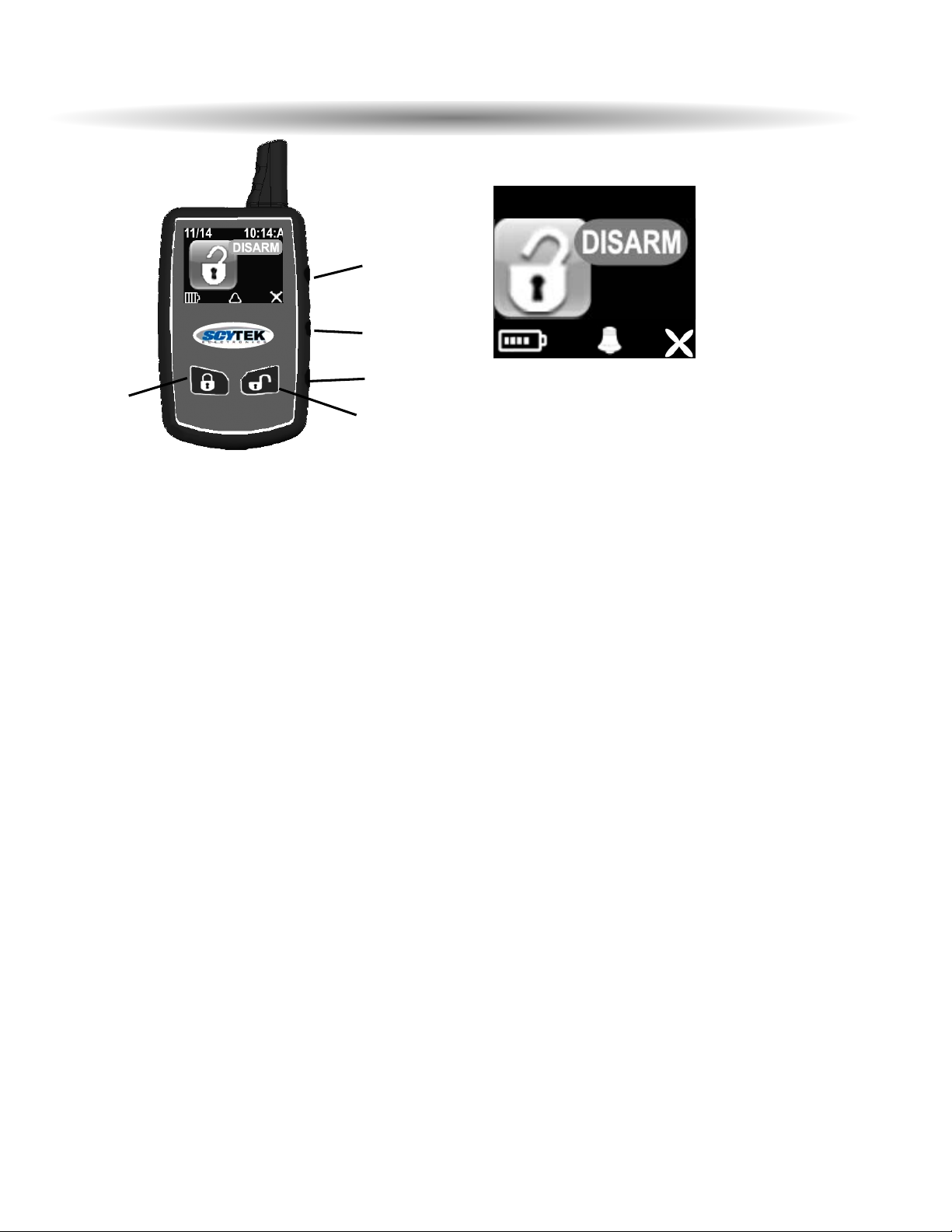
The 2-way Color remote transmitter is offering increased range and confirmation of any activated feature.
Page 1
Button 1
Arms and Locks* the system and when held for 5 seconds, activates the system’s Panic feature.
Button 1 also locks the doors when the system is in Valet Mode.
Button 2
Disarms and Unlocks* the system. Pressing Button 2 again operates the Passenger Unlock f eature
(if installed).
Button 2
also unlocks the doors when the system is in Valet Mode.
Button 3
Activates the Auxiliary 1 output normally used for trunk release (note trunk icon on button).
Button 4
Activates the Remote Start feature.
Button 5
is the Confirmation, Programming and the Page Shift button. Quickly pressing but ton 5 will activate
the Page 2 function. Pressing button 5 for 2 seconds activates the system’s confirmation feature which
will then display the current status of the system (armed, disarmed, engine running, etc.).
Page 2
Button 1
Silently Arms*/Locks the system.
Button 2
Silently Disarms*/Unlocks the system.
Button 3
Activates the Auxiliary 2 output.
Button 4
Aux 3 or Factory Rearm output.
Button 5
Not Implemented.
Page 3 & 4 are used as Page 1 & 2 for second car operation
System Confirmation
The 2-way transmitter's confirmation feature allows the current vehicle status to be displayed at any time.
To display system status:
1. Press and hold Button 5 until the display shows CONFIRM.
· The transmitter will beep once.
2. Release Button 5.
· The transmitter will beep once.
· The panel will display the current system status.
Button 1
Button 2
Button 3
Button 4
Button 5
11/16 3:10P
Battery
status
wakeup
alarm
enabled
autostart
enabled
22-WWAAYY CCOOLLOORR LLCCDD RREEMMOOTTEE TTRRAANNSSMMIITTTTEERR DDEESSCCRRIIPPTTIIOONN
Page 2 - Galaxy 5100RS
Galaxy 5100RS - Page 3
Press and hold Buttons 2 and 3 until pager program features are displayed.
Select pager setting by pressing buttons 2 or 3 to highlight the pager. Press button 1 to select the pager.
Setting Date & Time
Select Time Date setting by pressing buttons 3 or 4 to highlight the feature. Press button 1 to select it.
Use buttons 3 & 4 to highlight the parameter you wish to change, use buttons 1 & 2 to scroll up or down
to chage the time or date. Save the changes by pressing button 5.
Setting AutoStart Time
Select Start Time setting by pressing buttons 3 or 4 to highlight the feature. Press button 1 to select it.
Enable/Disable Auto Start
Select Auto Start on/off by pressing button 1.
Symbol is displayed if the Auto Start feature when enabled.
START TIME
ALARM CLOCK
SOUND ON
BACK
11/14 12:00P
TIME: 04:12P
DATE: 11/24
TIME DATE
ALARM CLOCK
SOUND ON
BACK
START SET
TIME: 08:00A
START TIME
AUTO ST ON
PAGER PARAMETERS SETTING
TIME DATE

Use buttons 3 & 4 to highlight the time parameter you wish to change, use buttons 1 & 2 to scroll up or
down to chage the time. Save the changes by pressing button 5.
Setting Alarm Clock
Select Alarm setting by pressing buttons 3 or 4 to highlight the feature. Press button 1 to select it.
Enable/Disable Alarm
Select Alarm Clock on/off by pressing button 1.
Use buttons 3 & 4 to highlight the time parameter you wish to change, use buttons 1 & 2 to scroll up or
down to chage the time. Save the changes by pressing button 5.
Symbol is displayed when Alarm Clock is enabled.
Selecting Sound/Vibration
Select Sound/Vibration setting by pressing buttons 3 or 4 to highlight the feature. Press button 1 to select
it.
TIME DATE
START TIME
SOUND ON
BACK
CLOCK ALARM
TIME: 08:00A
ALARM CLOCK
ALARM ON
CLOCK ALARM
ALARM ON
TIME: 08:00A
TIME DATE
START TIME
ALARM CLOCK
BACK
SOUND ON
START SET
AUTO ST ON
TIME: 08:00A
Page 4 - Galaxy 5100RS
Galaxy 5100RS - Page 5
Return to Previous Screen
Select Previous Screen by pressing buttons 3 or 4 to highlight the feature. Press button 1 to select it.
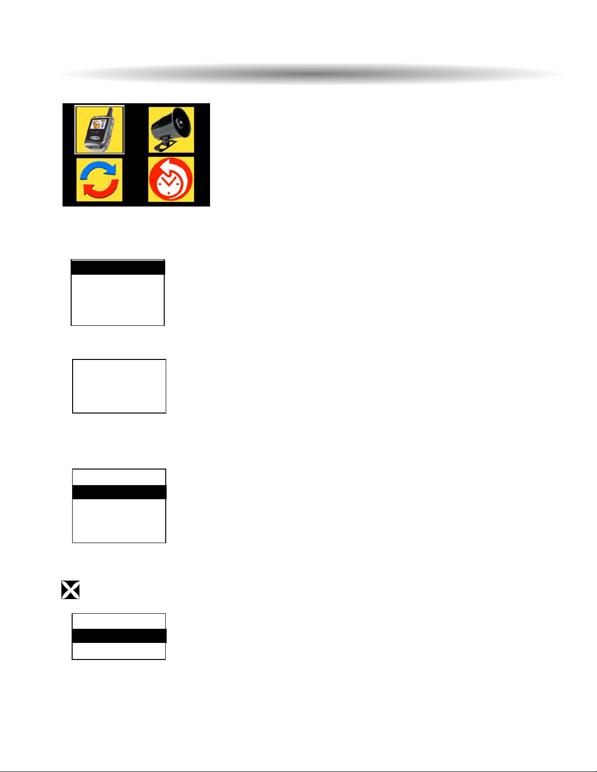
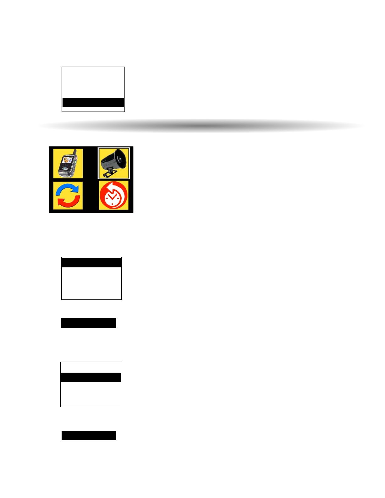
Press and hold Buttons 2 and 3 until System program features are high-lighted.
Select system setting by pressing buttons 3 or 4 to highlight the pager. Press button 1 to select the
system features.
Siren Chirp Enable/Disable
Select Siren Chirp setting by pressing buttons 3 or 4 to highlight the feature. Press button 1 to select it.
Sytem Responce
Passive Arm Enable/Disable
Select Passive Arm setting by pressing buttons 3 or 4 to highlight the feature. Press button 1 to select it.
Sytem Responce
TIME DATE
START TIME
ALARM CLOCK
SOUND ON
BACK
P ASSIVE ARM
COLD TEMP
HOT TEMP
BACK
SIREN CHIRP
SIREN CHIRP
COLD TEMP
HOT TEMP
BACK
PASSIVE ARM
FEATURE ON
FEATURE ON
Set System Parameters
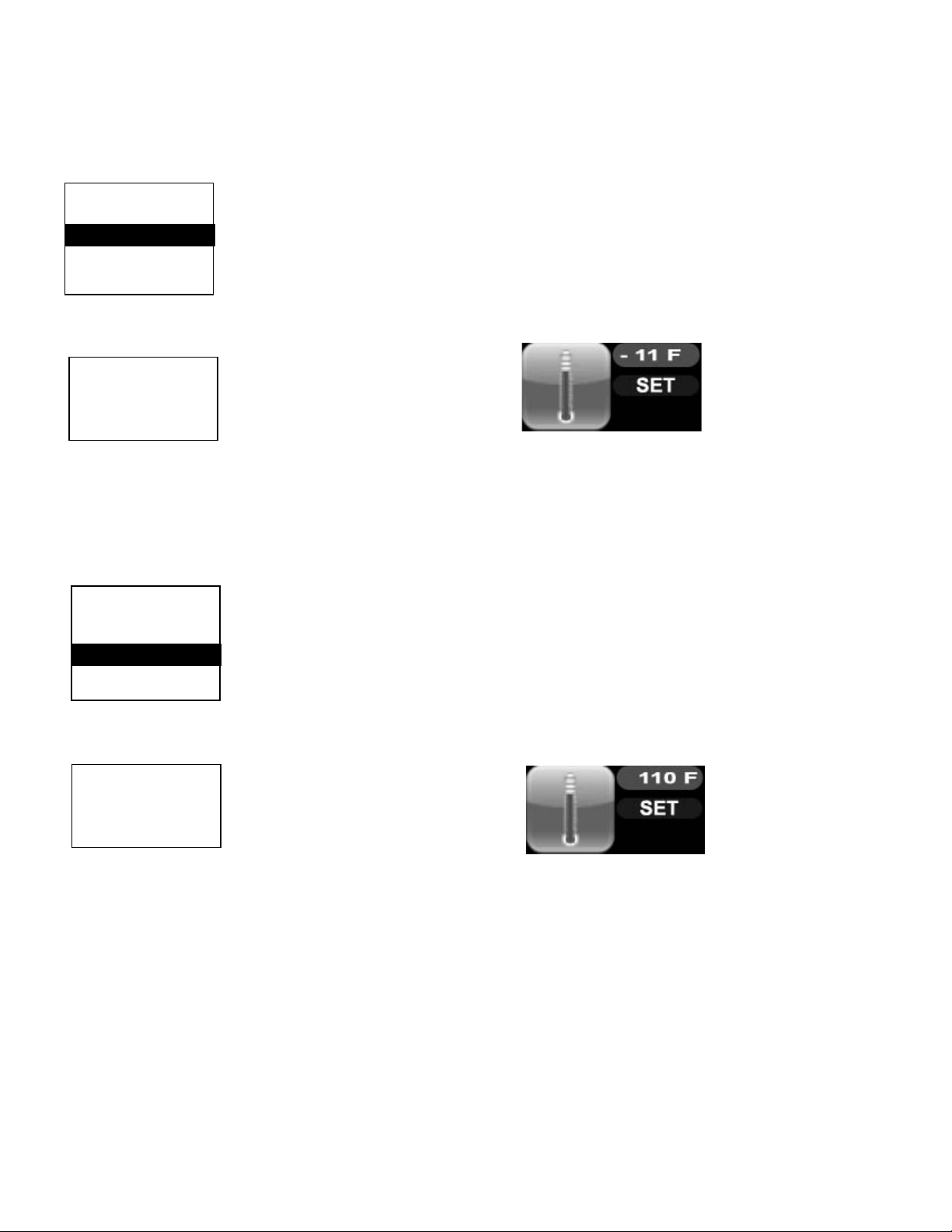
Setting AutoStart Cold Temperature Threshold
Select Cold Temp start setting by pressing buttons 3 or 4 to highlight the feature. Press button 1 to select
it.
Use buttons 1 & 2 to scroll up or down to chage the temperature threshold. Save the changes by
pressing button 5.
Setting AutoStart Hot Temperature Threshold
Select Cold Temp Time setting by pressing buttons 3 or 4 to highlight the feature. Press button 1 to
select it.
Use buttons 1 & 2 to scroll up or down to chage the temperature threshold. Save the changes by
pressing button 5.
SIREN CHIRP
PASSIVE ARM
HOT TEMP
BACK
COLD TEMP
AUTOSTART
SET
COLD TEMP
TEMP: - 11oF
AUTOSTART
SET
HOT TEMP
TEMP: 110oF
SIREN CHIRP
PASSIVE ARM
COLD TEMP
BACK
HOT TEMP
Security system responce
Security system responce
Page 6 - Galaxy 5100RS
Galaxy 5100RS - Page 7
Select Clock Sync setting by pressing buttons 1 or 2 to highlight the pager. Press button 3 to select the
pager. *
* Not available on the Galaxy 5100
Select Alarm History by pressing buttons 3 or 4 to highlight the feature. Press button 1 to select it.
The pager displays the alarm icon and time and date of the
occurrence.
Scroll through the events by pressing buttons 2 & 3.
Press button 5 to exit.
Synchronize System and Pager Clocks
Recall Alarm History
11/16 3:10P
Galaxy 5100RS - Page 8
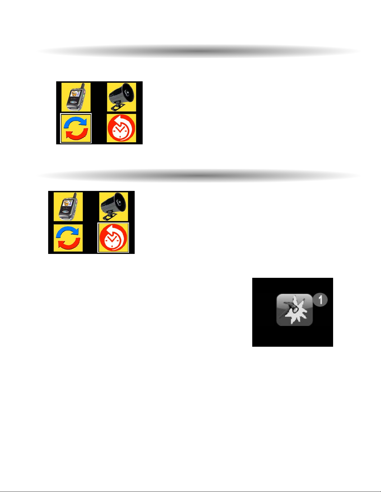
Pressing and holding transmitter button 5 will scroll through several transmitter programmable
options - TEMPERATURE, ENABLE COLD START, ENABLE HOT START, VALET MODE,
ENABLE AUTOSTART 1, ENABLE AUTOSTART 2.
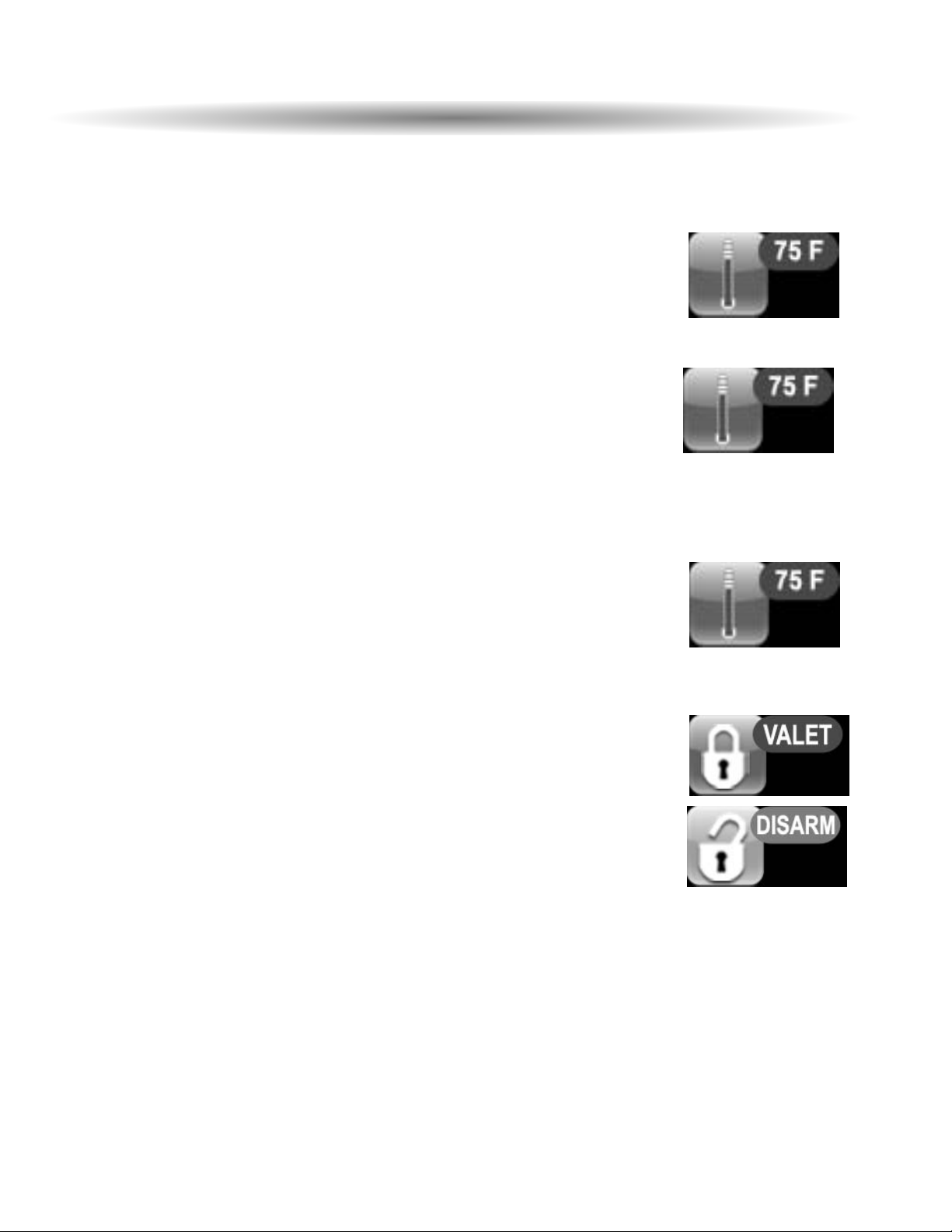
TEMPERATURE Check the temperature inside the vehicle
1. Press and hold Button 5 until the display shows TEMPERATURE
2. Release Button 5.
· The transmitter will beep four times.
ENABLE COLD START Auto Start Cold Temperature Activation Mode.
1. Press and hold Button 5 until the display shows ENABLE COLD START.
2. Release Button 5.
· The transmitter will beep.
· The display will show Auto Start Cold Temperature setting.
3. Press and hold Button 5 until the display shows CONFIRM.
4. Release Button 5.
· The transmitter will beep.
· The display will show "FEATURE ON" indicating that Auto Start Cold Temperature Activation
Mode is enabled.
ENABLE HOT START Auto Start Cold Temperature Activation Mode.
1. Press and hold Button 5 until the display shows ENABLE HOT START.
2. Release Button 5.
· The transmitter will beep.
· The display will show Auto Start Cold Temperature setting.
3. Press and hold Button 5 until the display shows CONFIRM.
4. Release Button 5.
· The transmitter will beep.
· The display will show "FEATURE ON" indicating that Auto Start Cold Temperature Activation
Mode is enabled.
VALET MODE Valet mode function sets and resets the security system valet mode.
** this function is enabled only when the system is disarmed/ unlocked.
Set or reset the Valet mode:
1. Press and hold Button 5 until the display shows VALET or DISARM.
· The transmitter will beep.
2. Release Button 5.
· The display will show VALET MODE .
· The transmitter will beep twice and the siren will chirp twice if the Valet
mode was reset. The symbol.
ENABLE AUTOSTART 1, ENABLE AUTOSTART 2 --
Not available on the Galaxy 5100
1. Press and hold Button 5 until the display shows ENABLE AUTOSTART 1 or
ENABLE AUTOSTART 2
2. Release Button 5.
· The transmitter will beep.
· The display will show Auto Start 1 or 2 time setting.
3. Press and hold Button 5 until the display shows CONFIRM.
4. Release Button 5.
· The transmitter will beep.
· The display will show "FEATURE ON" indicating that Auto Start 1 or 2 Activation
Mode is enabled.
PPrrooggrraammmmaabbllee
FFuunnccttiioonnss
uussiinngg
tthhee
CCoolloorr
RReemmootte
e
AUTOSTART 1
TIME: 8:00A
AUTOSTART 2
TIME: 5:00P
Page 9 - Galaxy 5100RS
Transmitter Lockout
Press and hold buttons 4 & 2 simultanously for 3
seconds to lockout the transmitter against accidental
transmission.
Release Transmitter Lockout
Press and hold buttons 4 & 2 simultanously for 3 seconds
to release the transmitter from Lockout.
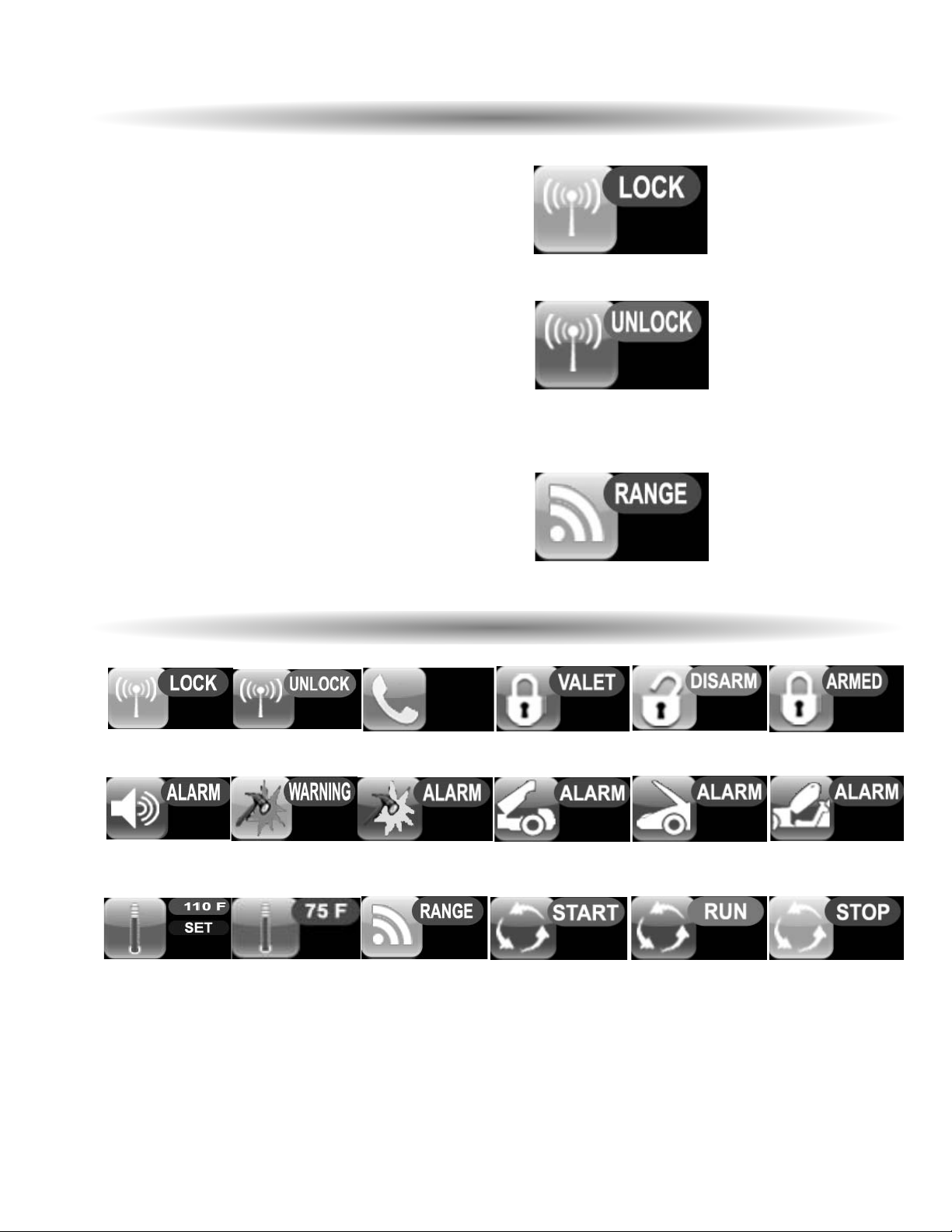
Out of Range Report
pager report if no responce from the unit.
Engine Start
Engine Run Engine Stoped
Armed
Disarmed
Warnaway
Ring
Alarm Hood
Alarm Door
Alarm Trunk
Alarm Sensor
Temperature
read
Valet
Transmitter
Unlocked
Transmitter
Locked
Alarm
Engine Start
Temperature
Set
ADDITIONAL FUNCTION
ICONS
Galaxy 5100RS - Page 10
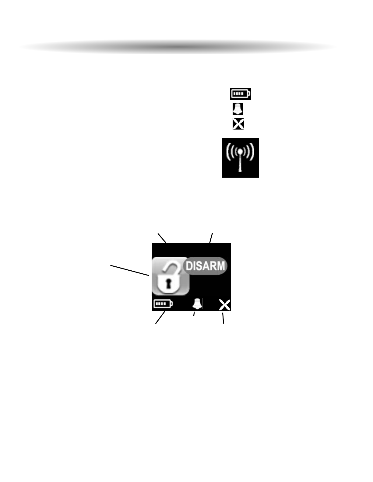
Time: time of day clock
Date/Engine Run Timer: date, or engine run minute timer if remote start activated (20 min
max).
Battery Status: displays remaining battery life.
Wakeup Alarm: displays Wakeup alarm ebnabled
Autostart: Remote Start Autostart enabled
Transmit: Pager transmission in progress
11/16 3:10P
Battery
status
wakeup
alarm
enabled
autostart
enabled
date/engine run timer
time
PPaaggeerr
SSttaattuuss
DDiissppllaay
y
System Status
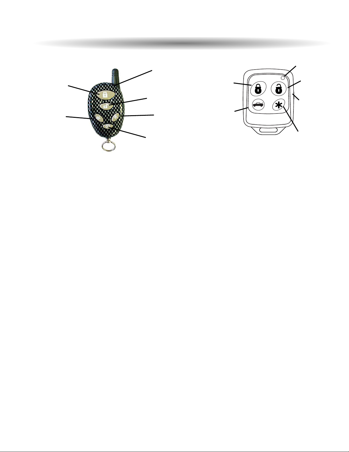
Standard Remote Transmitter Description
Depending on the model chosen, the Galaxy 5100RS Series will be supplied with one or two
T5 or T5-SP
5-button Remote Transmitters that are used to control the system’s operations.
Note: Using the optional PC or Pocket PC interface with the network software, it is possible to reconfigure
the functionality of the transmitter buttons. The standard (default) setting for operation of the transmitters
is described below.
Button 1
Arms and Locks the system and when held for 5 seconds, activates the system’s Panic feature.
Button 1 also locks the doors when the system is in Valet Mode.
Button 2
Disarms and Unlocks the system. Pressing Button 2 again operates the Passenger Unlock feature
(if installed).
Button
2 also unlocks the doors when the system is in Valet Mode.
Button 3
Activates the Auxiliary 1 output. This output will remain on for as long as the button is pressed.
Button 4
Activates the Remote Start feature.
Button 5
is the Page Shift button. Each time the Shift Button is pressed, the LED on the transmitter will
illuminate and the transmitter functions will shift to the next page, allowing access to another set of
features. Once shifted to another page (there are 4 pages total), the transmitter will remain on that page
for 10 seconds or until a button is pressed, then it will return to page 1. Under normal operation, only
pages 1 and 2 are used. Pages 3 and 4 are usually used for Two Car Operation (see page 3) or optional
expansion modules.
Shift then Button 1
Arms/Locks the system silently.
Shift then Button 2
Disarms/Unlocks the system silently.
Shift then Button 3
Activates the Auxiliary 2 output. This output will remain on for as long as the button
is pressed.
Shift then Button 4
Activates the Auxiliary 3/Factory rearm output.
Remote Transmitters
Button 2
Button 5
Button 3 Button 4
Page 2 - Galaxy 5100RS
LED
LED
Button 2
Button 4
Button 5
Button 1
Button 1
Button 3
T5-SP
T5
 Loading...