

Scytek electronic 2000RS Plus User Manual

22000000RRSS PPLLUUSS SSEERRIIEESS
REMOTE START SYSTEM
PRODUCT MANUAL

LLiimmiitteedd LLiiffeettiimmee WWaarrrraannttyy
This vehicle remote start system is warranted to the original purchaser, to be free from defects in
material and workmanship. The manufacturer will repair or replace at its option, and free of
charge for the first twelve (12) months, any part that proves defective in material or workmanship
under normal installation, use, and service, provided the product is returned to the manufacturer
freight prepaid. After the first 12 month warranty period there will be a maximum service charge
of $25.00 per calendar year (if required) for repair and/or replacement of any defective parts.
A copy of the original purchase receipt must accompany any products returned for warranty
service. Warranty is limited to defective parts and/or replacement parts only and excludes any
incidental, and consequential damages connected therewith.
The manufacturer of this system makes no warranty against the theft of the vehicle or its
contents. This warranty is not to be construed as an insurance policy against loss.
WARRANTY OF INSTALLATION LABOR, REMOVALAND RE-INSTALLATION CHARGES ARE
NOT THE RESPONSIBILITY OF THE MANUFACTURER.

1. About Your System . . . . . . . . . . . . . . . . . . . . . . . . . . . . . . . . . . . . . . . . . . . . . . . . . . . .Page 1
2. Remote Transmitters . . . . . . . . . . . . . . . . . . . . . . . . . . . . . . . . . . . . . . . . . . . . . . . . . . .Page 2
Remote Transmitter Description . . . . . . . . . . . . . . . . . . . . . . . . . . . . . . . . . . . . . . .Page 2
Adding/Replacing Transmitters . . . . . . . . . . . . . . . . . . . . . . . . . . . . . . . . . . . . . . .Page 3
Two Car Operation . . . . . . . . . . . . . . . . . . . . . . . . . . . . . . . . . . . . . . . . . . . . . . . .Page 3
Battery Replacement . . . . . . . . . . . . . . . . . . . . . . . . . . . . . . . . . . . . . . . . . . . . . .Page 3
3. System Operation . . . . . . . . . . . . . . . . . . . . . . . . . . . . . . . . . . . . . . . . . . . . . . . . . . . . .Page 6
Remote Locking . . . . . . . . . . . . . . . . . . . . . . . . . . . . . . . . . . . . . . . . . . . . . . . . . .Page 6
Remote Unlocking . . . . . . . . . . . . . . . . . . . . . . . . . . . . . . . . . . . . . . . . . . . . . . . .Page 6
Optional Panic Mode . . . . . . . . . . . . . . . . . . . . . . . . . . . . . . . . . . . . . . . . . . . . . . .Page 6
Valet Mode . . . . . . . . . . . . . . . . . . . . . . . . . . . . . . . . . . . . . . . . . . . . . . . . . . . . .Page 6
4. Remote Start Features . . . . . . . . . . . . . . . . . . . . . . . . . . . . . . . . . . . . . . . . . . . . . . . . .Page 7
Remote Starting . . . . . . . . . . . . . . . . . . . . . . . . . . . . . . . . . . . . . . . . . . . . . . . . . .Page 7
Shut Down . . . . . . . . . . . . . . . . . . . . . . . . . . . . . . . . . . . . . . . . . . . . . . . . . . . . .Page 7
Quick Stop . . . . . . . . . . . . . . . . . . . . . . . . . . . . . . . . . . . . . . . . . . . . . . . . . . . . .Page 7
Automatic Start Mode . . . . . . . . . . . . . . . . . . . . . . . . . . . . . . . . . . . . . . . . . . . . . .Page 8
Starter Diagnostics . . . . . . . . . . . . . . . . . . . . . . . . . . . . . . . . . . . . . . . . . . . . . . . .Page 8
5. Extended Features . . . . . . . . . . . . . . . . . . . . . . . . . . . . . . . . . . . . . . . . . . . . . . . . . . . .Page 9
Ignition Door Locking . . . . . . . . . . . . . . . . . . . . . . . . . . . . . . . . . . . . . . . . . . . . . .Page 9
Ignition Door Unlocking . . . . . . . . . . . . . . . . . . . . . . . . . . . . . . . . . . . . . . . . . . . .Page 9
Dome Light Activation . . . . . . . . . . . . . . . . . . . . . . . . . . . . . . . . . . . . . . . . . . . . .Page 9
Auxiliary Function Outputs . . . . . . . . . . . . . . . . . . . . . . . . . . . . . . . . . . . . . . . . . .Page 9
Turbo Timer Feature . . . . . . . . . . . . . . . . . . . . . . . . . . . . . . . . . . . . . . . . . . . . . . .Page 9
6. System Installation . . . . . . . . . . . . . . . . . . . . . . . . . . . . . . . . . . . . . . . . . . . . . . . . . . .Page 10
Mounting the Control unit . . . . . . . . . . . . . . . . . . . . . . . . . . . . . . . . . . . . . . . . . .Page 10
7. System Wiring . . . . . . . . . . . . . . . . . . . . . . . . . . . . . . . . . . . . . . . . . . . . . . . . . . . . . .Page 11
6-Pin Starter Harness . . . . . . . . . . . . . . . . . . . . . . . . . . . . . . . . . . . . . . . . . . . . .Page 11
20-Pin Main Harness . . . . . . . . . . . . . . . . . . . . . . . . . . . . . . . . . . . . . . . . . . . . . .Page 11
Plug-in Connectors . . . . . . . . . . . . . . . . . . . . . . . . . . . . . . . . . . . . . . . . . . . . . . .Page 12
8. Jumper Settings . . . . . . . . . . . . . . . . . . . . . . . . . . . . . . . . . . . . . . . . . . . . . . . . . . . . .Page 13
Jumper Selection . . . . . . . . . . . . . . . . . . . . . . . . . . . . . . . . . . . . . . . . . . . . . . . .Page 13
9. System Programming . . . . . . . . . . . . . . . . . . . . . . . . . . . . . . . . . . . . . . . . . . . . . . . . .Page 14
Entering System Programming . . . . . . . . . . . . . . . . . . . . . . . . . . . . . . . . . . . . . . .Page 14
Default Reset . . . . . . . . . . . . . . . . . . . . . . . . . . . . . . . . . . . . . . . . . . . . . . . . . . .Page 14
Programmable System Options . . . . . . . . . . . . . . . . . . . . . . . . . . . . . . . . . . . . . .Page 14
Branch Table . . . . . . . . . . . . . . . . . . . . . . . . . . . . . . . . . . . . . . . . . . . . . . . . . . .Page 15
10. Wiring Diagrams . . . . . . . . . . . . . . . . . . . . . . . . . . . . . . . . . . . . . . . . . . . . . . . . . . . . .Page 17
11. Door Lock Diagrams . . . . . . . . . . . . . . . . . . . . . . . . . . . . . . . . . . . . . . . . . . . . . . . . . .Page 18
12. Two Stage Door Lock Diagrams . . . . . . . . . . . . . . . . . . . . . . . . . . . . . . . . . . . . . . . . . .Page 19
13. Technical Information . . . . . . . . . . . . . . . . . . . . . . . . . . . . . . . . . . . . . . . . . . . . . . . . .Page 23
14. Wiring Diagram . . . . . . . . . . . . . . . . . . . . . . . . . . . . . . . . . . . . . . . . . . . . . . . . . . . .Back Page
TTaabbllee ooff CCoonntteennttss


The ScyTek Galaxy Starter is a started-of-the-art remote starting system featuring a built-in "ScyNet
Network Port" that allows direct connection of optional accessory modules and a PC interface offering
expanded system operation. With proper installation this system will provide superior protection and
performance for many years to come.
The Galaxy Starter’s built-in remote start feature is designed to offer maximum convenience by remote
starting your vehicle’s engine, turning on the heater/air conditioner, and then running for a pre-determined
time to provide a comfortable environment once you enter your vehicle.
To ensure the safety and security of the system while it is remote started, the Galaxy Starter employs
several safeguards. In the event the brake pedal is pressed while the engine is remotely running, the
remote start will immediately shutdown to prevent unauthorized users from attempting to drive the vehicle.
The system is equipped with a hood pin input to prevent access to the engine compartment while the
vehicle is remotely running. Finally, the Valet Mode prevents the remote start feature from operating in the
event the vehicle is to be serviced.
System Contents:
• Main Unit with built-in ScyNet Network Interface Port
• Two 5-Button Random Code Remote Transmitters
• Status LED
• Coded Emergency Override / Valet Switch
Optional ScyNet Network Interface Accessories:
• ScyNet Network Interface Software
• Two-Way FM Paging Module w/ LCD Transmitter
Options and Convenience Features
*
This ScyTek system includes several optional inputs and outputs allowing the creation of a completely
personalized convenience system by offering many optional features such as:
*May require additional parts and/or labor, see store for details.
Galaxy 2000RS Plus - Page 1
· Second Car Operation
· Keyless Entry
· Two Stage Door Unlocking
· Horn Honk
· Illuminated Entry
· Remote Window Control
· Power Trunk / Hatch Release
· Remote Head Lamp Control
AAbboouutt YYoouurr SSyysstteemm
PLEASE NOTE:
Some of the features described in this manual may require additional parts and/or labor, and may not be included
as part of the standard installation of this unit. Additionally, many features of this security system have
selectable options that must be activated or programmed during the system’s installation. These items will be
identified in the following sections. Please discuss these features and any questions you may have regarding the
installation of this product with Your Authorized Dealer.

Remote Transmitter Description
The Galaxy Starter is supplied with two 5-button Remote Transmitters used to control system operations.
Note: Using the optional PC or Pocket PC interface with the network software, it is possible to reconfigure
the functionality of the transmitter buttons. The standard (default) setting for operation of the transmitters
is described below.
Button 1
Locks the doors and when held for 2 seconds, activates the system’s Panic feature.
Button 2
Unlocks the doors. Pressing Button 2 again operates the Passenger Unlock feature (if installed).
Button 3
Activates the Auxiliary 1 output. This output will remain on for as long as the button is pressed.
Button 4
Activates the Remote Start feature.
Button 5
is the Page Shift button. Each time the Shift Button is pressed, the LED on the transmitter will
illuminate and the transmitter functions will shift to the next page, allowing access to another set of
features. Once shifted to another page (there are 4 pages total), the transmitter will remain on that page
for 10 seconds or until a button is pressed, then return to page 1. Each time a transmitter button is pressed
and held, the LED will flash a number of times to indicate from which page it is transmitting. Under
normally operation, only pages 1 and 2 are used. Pages 3 and 4 are usually used for Two Car Operation
(see page 3) or optional expansion modules.
Shift then Button 1
Locks the system silently (only used if the optional audible status output is used).
Shift then Button 2
Unlocks the system silently (only used if the optional audible status output is used).
Shift then Button 3
Activates the Auxiliary 2 output. This output will remain on for as long as the button is
pressed.
Shift then Button 4
Activates the Auxiliary 3 output. This output will remain on for as long as the button is
pressed.
Page 2 - Galaxy 2000RS Plus
RReemmoottee TTrraannssmmiitttteerrss
Button 1 Button 2
Button 5
LED
Button 3 Button 4

Adding/Replacing Transmitters
To replace lost or stolen transmitters or to add additional transmitters into the system, have all desired
transmitters ready and follow the steps below.
Note: Up to 4 transmitters can be programmed to operate the system. To erase any previously stored
transmitter codes, be sure to program all 4 transmitter memory locations.
To program the transmitter(s):
1. Turn on the ignition key On, Off, On, Off, and back On.
· The parking lights will flash 3 times.
2. Press and hold the Override switch for 5 seconds.
· The parking lights will flash 5 times.
· The LED will illuminate.
3. Press Button 1 on the first transmitter.
· The parking lights will flash once.
4. Press Button 1 on the first transmitter again.
· The parking lights will flash twice to indicate it has learned the code.
5. Repeat steps 3 and 4 for each transmitter (up to 4).
6. Turn off the ignition key.
· The parking lights will flash 3 times.
Two Car Operation
If two vehicles are equipped with Galaxy Starter systems, for convenience both can be operated using the
same remote transmitter. If all four transmitters are to be used with both cars, program transmitters A and
B into the first vehicle in the manner described above. Program transmitters C and D by pressing the Shift
button twice before performing steps 3 and 4 above.
When finished programming the first vehicle, program transmitters C and D into the second vehicle as
normal, then program transmitters A and B by pressing the Shift button twice before performing steps 3
and 4 above.
When programmed in this manner, the driver of the first car can also operate the second vehicle by pressing
the Shift button twice and the desired function button.
Battery Replacement
Your Galaxy Remote Transmitter uses a 12 volt alkaline battery (type 23A), which will require replacement
in time. Depending on the amount of use, the battery may last up to six months or more before it needs
replacement.
When the battery needs replacing, the system’s operating range will decrease or the transmitter LED may
not be as bright.
In order to change the battery, first remove 2 screws from the back of the transmitter and separate the top
and bottom halves of the case.
While replacing the battery make sure that the positive and negative terminals are positioned correctly, then
carefully reassemble the transmitter case.
Galaxy 2000RS Plus - Page 3
Page 4 - Galaxy 2000RS Plus
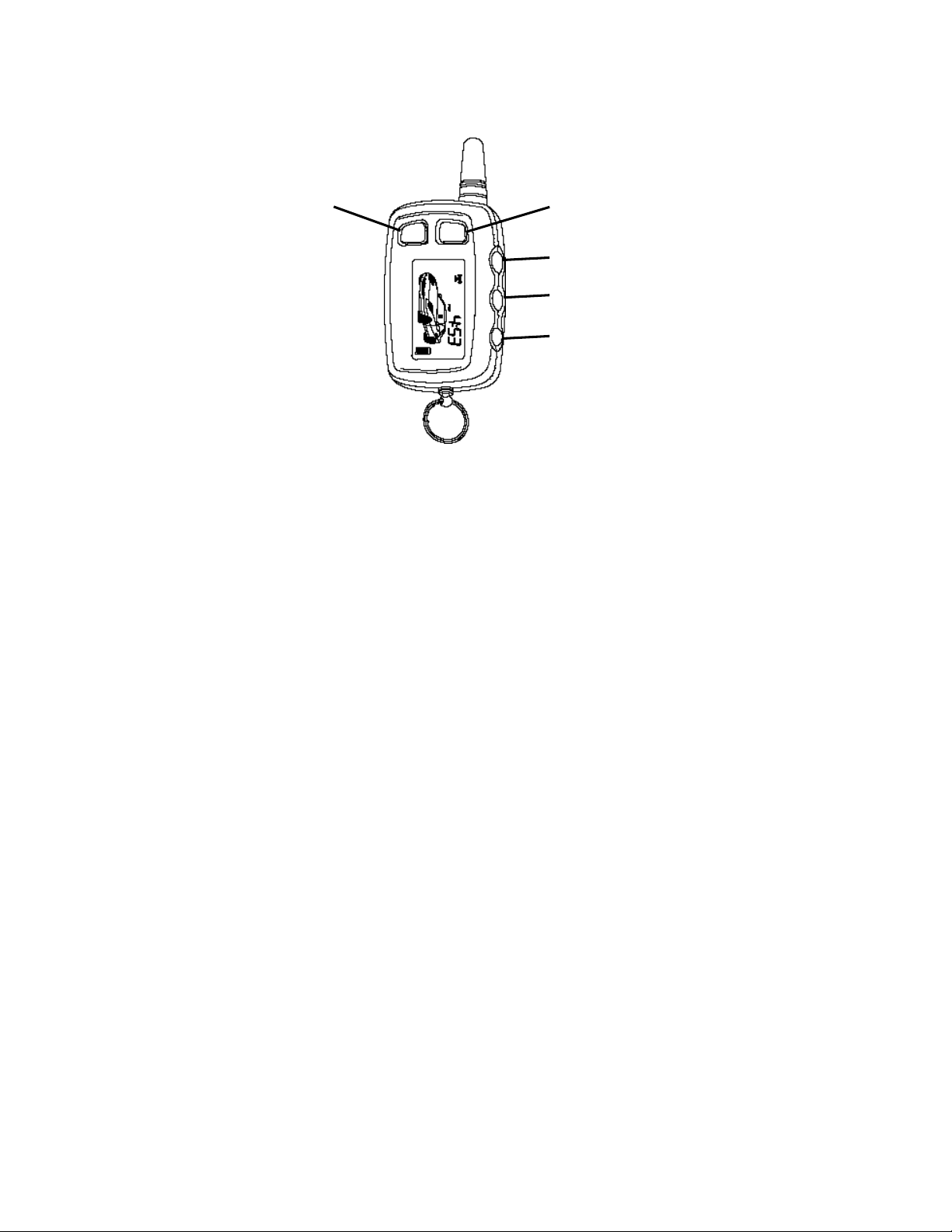
Optional 2-way LCD Remote Transmitter Description
The Galaxy 2000RS Plus is compatible with the optional 2-way LCD remote transmitter, offering increased
range and confirmation of any activated features.
Button 1
Locks and Unlocks the system and when held for 2 seconds, activates the system’s Panic feature.
Button 1 also locks/unlocks the doors when the system is in Valet Mode.
Button 2
Activates the Remote Start feature.
Button 3
Activates the Auxiliary 1 output normally used for trunk release (note trunk icon on button).
Button 4
Activates the Auxiliary 2 output. This output will remain on for as long as the button is pressed.
Button 5
is the Confirmation and Programming button. Quickly pressing button 5 will activate the LCD
display’s backlighting for use in the dark. Pressing button 5 for 2 seconds activates the system’s
confirmation feature which will then display the current status of the system (armed, disarmed, engine
running, etc.).
Adding/Replacing Optional 2-way LCD Transmitters
When adding an optional 2-way LCD transmitter to the system, follow these steps:
1. Turn on the ignition key On, Off, On, Off, On, Off, and back On. (Key On 4 times)
· The siren will chirp 4 times.
2. Press and hold the Override switch for 5 seconds.
· The siren will chirp 4 times.
· The LED will illuminate.
3. Press Button 1 on the first transmitter.
· The siren will chirp once.
4. Turn off the ignition key.
5. Repeat steps 1-4 to add an additional 2-way transmitter.
Button 1 Button 2
Button 3
Button 4
Button 5

Galaxy 2000RS Plus - Page 5
LCD Transmitter Battery Replacement
Your Galaxy Remote Transmitter uses a 1.5 volt AAA alkaline battery, which will require replacement in time.
Depending on the amount of use, the battery may last up to six months before it needs replacement. When
the battery needs replacing, the system’s operating range will decrease, the LCD display will show only one
of three bars in the battery icon, or the display and sounds may suddenly stop and start as the battery
voltage drops below minimum.
In order to change the battery, first slide the battery door locking pin to the side. Carefully slide the battery
cover downward until it is free. While replacing the battery make sure that the positive and negative
terminals are positioned correctly, then carefully reassemble the transmitter case.
 Loading...