

Scytek Astra 20 User's Manual
12V+
(IGNITION)
ORANGE
WIRE
Items Supplied with the System:
• Main unit
• Plug In LED
• Plug in program switch
• Harness kit
• Dual Stage Electronic Shock sensor
• 120dB 6-tone siren
• Owner’s manual
Before you begin the installation:
• This product must be installed by qualified
personnel according to these instructions.
• Always use a multimeter to verify vehicle
wiring.
• Verify LED and override switch placement,
with the vehicle’s owner, before mounting
components.
Installation Instructions:
1. Mounting the module:
Mount the module in a suitable location
inside the vehicle that will be difficult for a
thief to locate, while allowing for a
convenient installation position. Wire tie
or screw the module securely.
2. Mounting the Siren:
Mount the siren in a suitable location in
the engine compartment, away from hot or
moving engine parts such as exhaust
manifolds, turbochargers, fan belts, etc.
Make sure that there is no outside access
to the siren from underneath the vehicle
or through the grill.
Point the siren down so that water may
not accumulate inside the siren bell.
Connect the siren’s black wire to a solid
ground using a star washer and ring
terminal.
Route the red wire through the firewall
and cover with tape or split loom tubing
for protection. Always use either an
existing grommet or a new hole with the
proper size grommet to protect the wire
from chaffing.
3. Mounting the shock sensor:
Using a cable tie, mount the shock sensor
inside the vehicle to either the steering
column, a large wire harness, or a dash
brace. Be sure that the adjustment screw
1
STATUS INDICATOR (LED) FUNCTIONS
Off= System off in Active Mode
Slow Flash= System Armed
Rapid Flash= Passive Pre Arm State
Rapid Flash (after disarm)= System was triggered
On Solid= In Valet
On Solid= (After passive prearm or active arm) 2
second final prearm state
On Solid= (when disarmed, and not in Valet)
Door open.
SIREN CHIRP STATUS
1 chirp= system armed
2 chirps= system disarmed
3 chirps= System disarmed, but alarm was
triggered while away.
4 chirps= Alarm armed but there is a trigger that
remains open. (This occurs 25 seconds after
system was armed)
5 rapid chirps= Alarm armed, shock sensor warn
away output was triggered.
TRIGGER ZONE INDICATOR
2 Flashes = Door Trigger
3 Flashes = Shock trigger
4 Flashes = Warn away trigger
INSTALLATION MANUAL
Security Upgrade for
Factory Keyless Entry
700 01/01 - Rev. 2
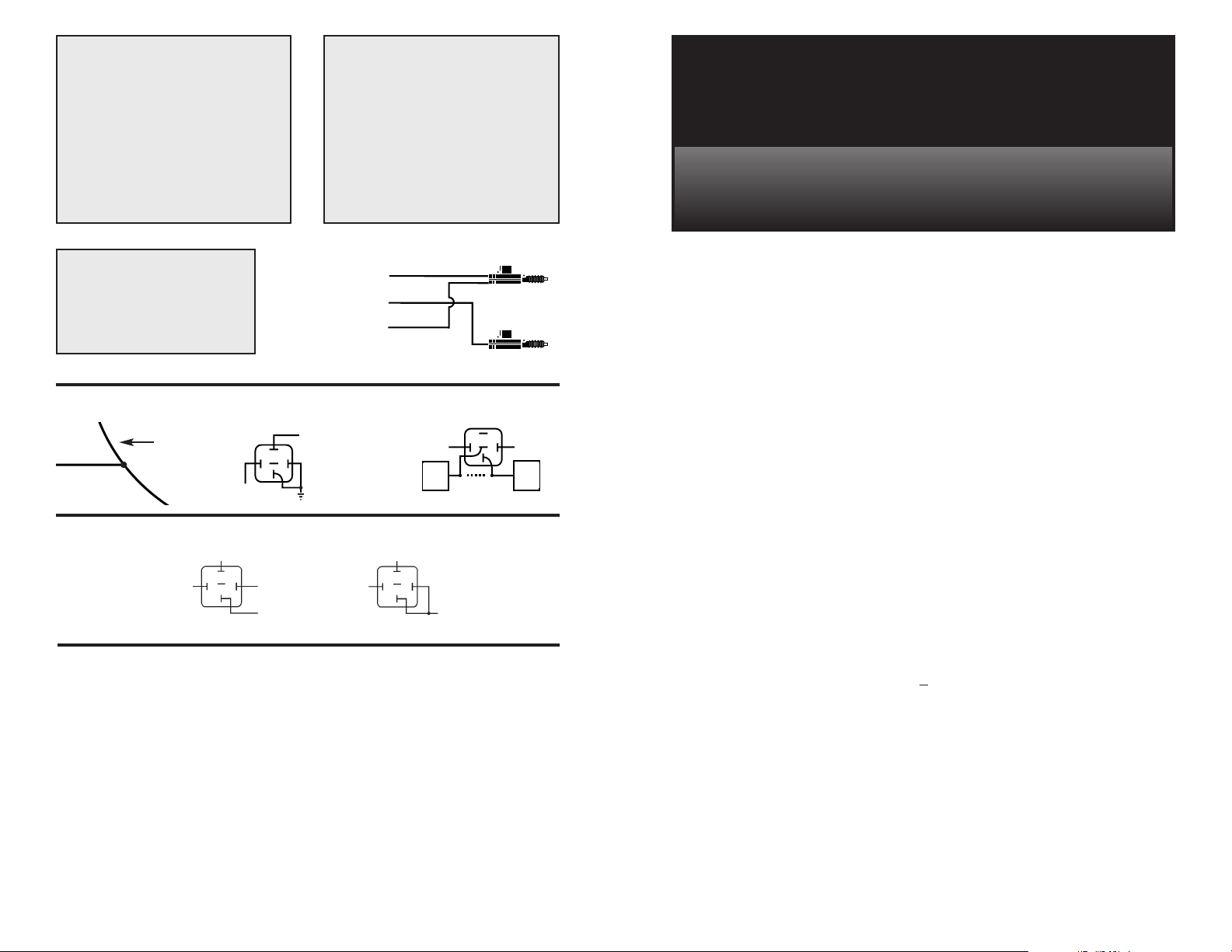
FOR POSITIVE
PARKING LIGHTS
VEHICLE
PARKING
LIGHT
WIRE
TO VEHICLE
PARKING LIGHT
CIRCUIT
WHITE
WHITE
FOR NEGATIVE
PARKING LIGHTS
(MOST JAPANESE VEHICLES)
87
85
30
86
87a
87
85
30
86
87a
TO (-) HORN (+) HORN
GRAY
GRAY
12V(+)
CONSTANT
12V (+)
CONSTANT
GROUND
POSITIVE
HORN
NEGATIVE
HORN
HORN HONK
RELAY DIAGRAM:
STARTER DISABLE
IGNITION
SWITCH
STARTER
GREEN
RED
BLUE
UNLOCK
DRIVER'S
DOOR
LOCK
PASSENGER'S
DOOR
MODE 2
OPERATION
87
87a
8586
30
FUEL
PUMP
87
87a
8586
30
CUT
x
x
FUSE
BLOCK

on the sensor is accessible for adjustment.
Plug the shock sensor harness into the 4pin white connector on the main module.
4. Installing the Status
Indicator (LED):
Locate a place where there is enough
depth for the LED to fit all the way in, and
where it will be easily visible from outside
the vehicle. Carefully drill the appropriate
size hole (7/16”) and run the 2 pin red
connector through to the matching red
connector on the module. Push the LED
into the hole, making sure it fits snugly.
5. Installing the Valet Switch:
Mount the valet/override switch in a
hidden location that can still be found by
the customer for emergency override
situations. Run the 2 pin blue connector
through to the matching blue 2 pin
connector on the module.
6. Flashing Parking Light
Output (white wire):
Using a volt/ohm meter, locate the wire
(usually on the head light switch) that
shows +12V when only the parking lights
are switched on. European vehicles may
require an additional relay if they have
separate wires for the left and right side
parking lights. This wire has a maximum
output of 15 amps. Do not connect to head
light circuits. (See diagram section).
7. 12V+ Power Input (red wire):
Connect the red fused wire on the main
harness to the vehicle’s battery.
8. Siren Output (brown wire):
Connect the brown wire on the main
harness to the red wire from the siren.
9. Ground Input (black wire):
Connect the black wire to a solid chassis
ground.
10. Optional Armed Output
(orange wire):
This wire provides a ground output when
the alarm is armed, to control an optional
Starter Disable Relay. Using a volt/ohm
meter locate the starter wire (normally a
heavier gauge wire) coming from the
ignition switch. Cut the wire that shows
+12V during cranking only. The vehicle
should not be able to start. Connect a relay
as shown in diagram section.
11. Horn output (gray wire):
This wire provides a pulsed output to drive
a relay to honk the horn when the alarm is
triggered. Connect to a relay as shown in
diagram section on back page.
12. Negative door input (green
wire):
Connect the green wire from the module
to the wire that shows ground when all of
the doors are opened. Verify with a
volt/ohm meter. Make sure that all doors
when opened separately make the target
wire provide a ground output.
13. Hood/Trunk switch input
(blue wire):
Connect the blue wire to the hood and/or
trunk pin switch that shows ground when
opened.
14. Positive Door input (violet
wire):
Connect the violet wire from the module to
the wire that shows 12V+ when all of the
doors are opened. Verify with volt/ohm
72
SYMPTOM
Parking lights do not flash.
Vehicle starts when armed.
Car horn honks when system
disarmed and door is opened.
Alarm system intermittently
works.
Car won't start;
Alarm won't function properly.
Unit is triggered any
time it is armed.
Remote Control does not arm
or disarm alarm.
Valet does not work.
Flashing output does not work.
Remote Control does not
disarm alarm.
Alarm doesn’t Arm/Disarm.
Alarm will not Passively Arm.
PROBABLE CAUSE
Wrong wire connected to the
White wire, or requires a
negative output.
Wrong starter wire was cut.
Vehicle factory security system
needs to be disarmed.
Bad power and ground
connections.
Vehicle battery dead or drops
below 7.5 volts when trying to
start the vehicle.
Sensor not adjusted correctly,
BLUE or GREEN wire shorted to
ground.
Wrong polarity for door lock
input. Program #1:
ON=(-) pulse OFF=(+) pulse
or...not connected to proper
door lock/unlock wires.
Bad switch or wrong activation
sequence.
Bad connection on WHITE wire
or the output polarity is wrong
for the circuit being driven.
Programs #2 or 3 are not set in
the correct position.
Alarm in Valet Mode, ignition
input has voltage on it. Make sure
the power and ground wires
show 12V+.
Program #6 is OFF, wrong polarity
door input wire,Yellow ignition
input has 12V+ on it.
SUGGESTED CORRECTION
Correct the wire connected to
the White wire, using a SPDT
relay reverse polarity on white
wire (see diagrams).
Locate proper starter wire and
reconnect.
Locate disarm wire (drivers kick
panel?) use neg. unlock pulse to
disarm factory system.
Replace and secure power and
ground connections.
Replace battery or charge.
Readjust sensor.
Disconnect the BLUE or GREEN
wire to see if symptom stops, if
so check wires for short.
Check polarity on door lock
wires with correct Program
position.
Repair or replace switch or check
user instructions for proper
activation sequence.
Check WHITE wire. Connect a
Relay to this wire and apply the
opposite polarity to the
circuit being driven.
See mode explanation Page 5.
Take alarm out of Valet mode turn key off - wrong wire
connected to yellow wire main
harness.
Correct Program #6. Correct
door switch polarity,change
ignition input wire, make sure
alarm is not in Valet.
TROUBLESHOOTING (continued)
 Loading...