


WIRED
CONTROLLER
MINI CHILLER
USER MANUAL
KJR-120F
AIR CONDITIONING

“Originalinstructions”

Chiller wired controller
1.1 Mini chiller wired controller: KJR-120F
1.1.1Specifications
Model
Description
power adapter
230-240V~50Hz
KJR
-
120F
Touch key and backlight function
Input Voltage
10V AC
Operating environment
temperature
-15
ºC~+43ºC
Operating RH
RH 40%~RH 90%
Chiller wired controller
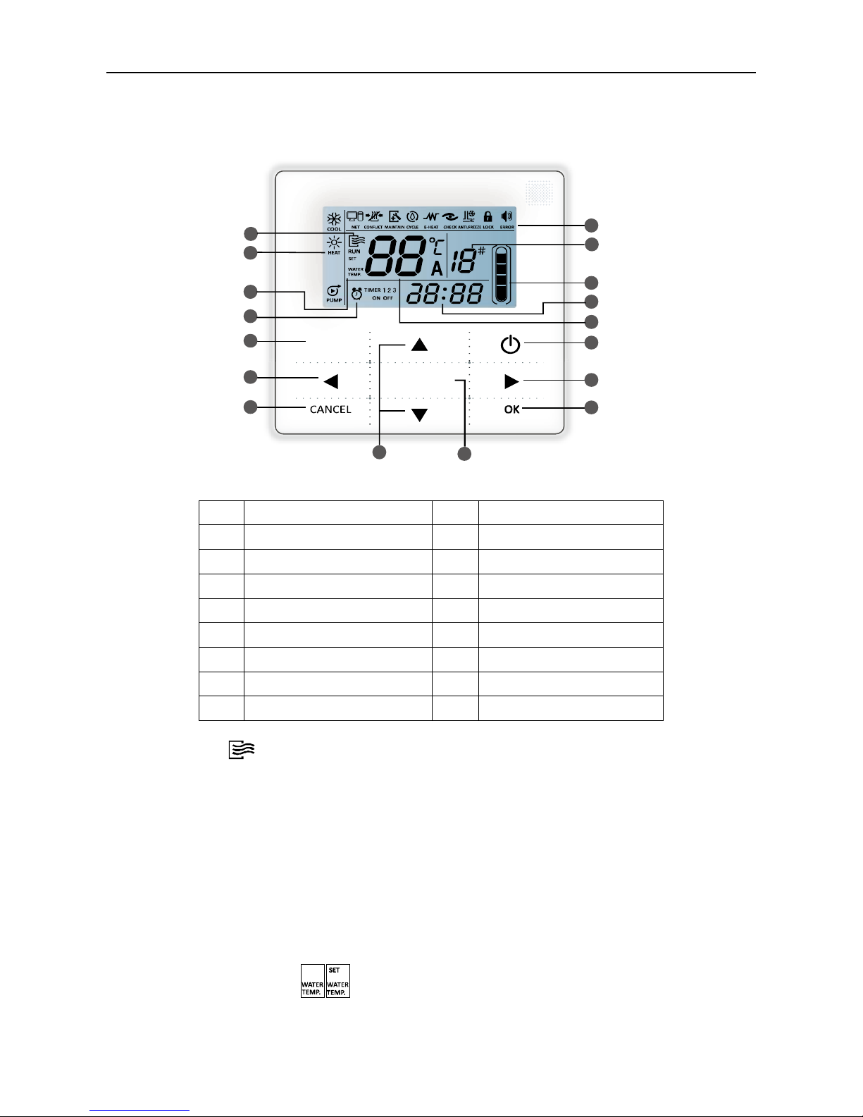
1.1.2 Button introduction
Item
Description
Item
Description
1
Operation icon
9
Water temperature
2
Mode area
10
ON/OFF key
3
Water temperature
11
Right, left key
4
Timer ON/OFF
12
OK key
5
Function icon
13
Function key
6
On-line unit qty. indication
14
Add, reduce key
7
Reserved
15
Cancel key
8
Clock
16
Mode key
1. Operation icon :
Indicate the ON and OFF status; when it is ON, it will display; when it is OFF, it will disappear;
2.Mode area:
Indicate the main unit operating mode;
3. Water temperature
Two status can be displayed: ;
14
13
3
1
2
4
16
11
15
5
6
7
8
9
10
11
12
(Long press 3s
for cancelling timing)
(Long press 3s
for unlocking)
MODE
FUNCTIONS
Chiller wired controller
4. Timing ON/OFF indication :
Indicate the timer information;
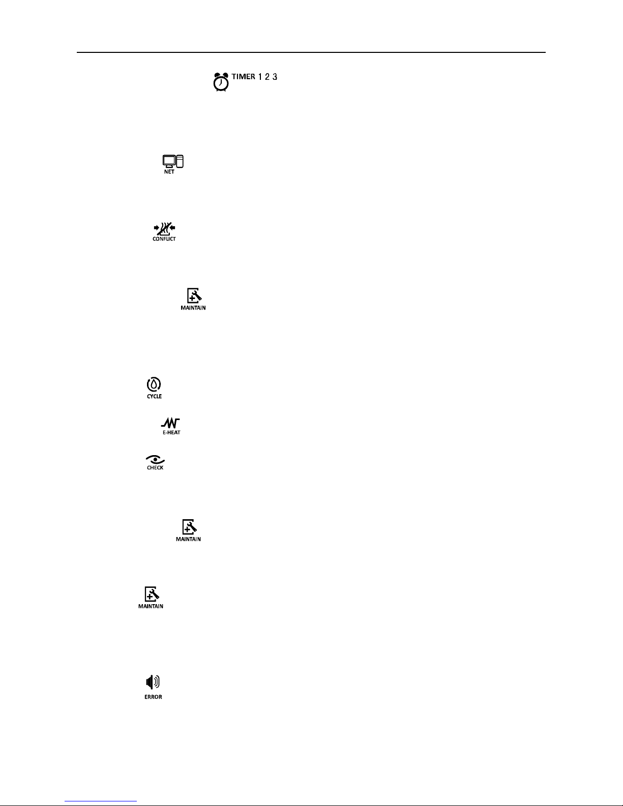
5. Function icon;
1) Computer
Display when connects to computer.
2) Conflict
Displays when the unit operation forced cooling mode.
3) Maintenance
Displays when the unit is needed. Press″MODE″ key for 3 seconds to cancel the icon and timing will
restart until next maintenance.
4) Cycle : The reserved icon
5) E-heating : The reserved icon.
6) Check
Display when check function is operated;
7) Anti-freezing
Displays when ambient temperature is low which means the main unit need anti-freezing action
8) Lock
Displays when no key operation for 2 minutes and all keys are locked. Press ―OK‖ key for 3 seconds
to unlock;
9) Error : Displays when error or protection occurs and means the unit need maintainence by
professionals.

Chiller wired controller
6. On-line unit qty. indication:
Under normal status display the quantity of the units connected to the wired controller; under check status
display the device serial number.
7. Water level indication: The reserved icon
8. Clock:
Under normal status display clock; during timer setting it displays the setting timing time.
9. Water temperature:
Under normal status display water temperature; during water temperature setting it displays the setting
numerical value; under spot check status display spot check parameter;
10. ON/OFF key: On and Off functions.
11. Right, Left key:
Under main page to press this key can query the setting water temperature; Press right key to shift to the
next step setting under timing setting status; Press these keys to turn over the unit parameter information
under check status.
12. OK key:
After setting the parameter then press this key to confirm. After keys locking then long press this key for 3
seconds to unlock.

Chiller wired controller
13. Function key:
Setting water temperature, timing and clock etc; Press FUNCTION key for 3 seconds to enter check
status, setting unit number and forced open water pump.
14. Add, Reduce key:
Move up or move down values of temperature, timing etc.
15. Cancel key:
During setting parameters press this key to cancel setting. After timing setting and then long press this
key 3 seconds to cancel timing.
16. Mode key: Power on the cooling function,heating function or water pump function.
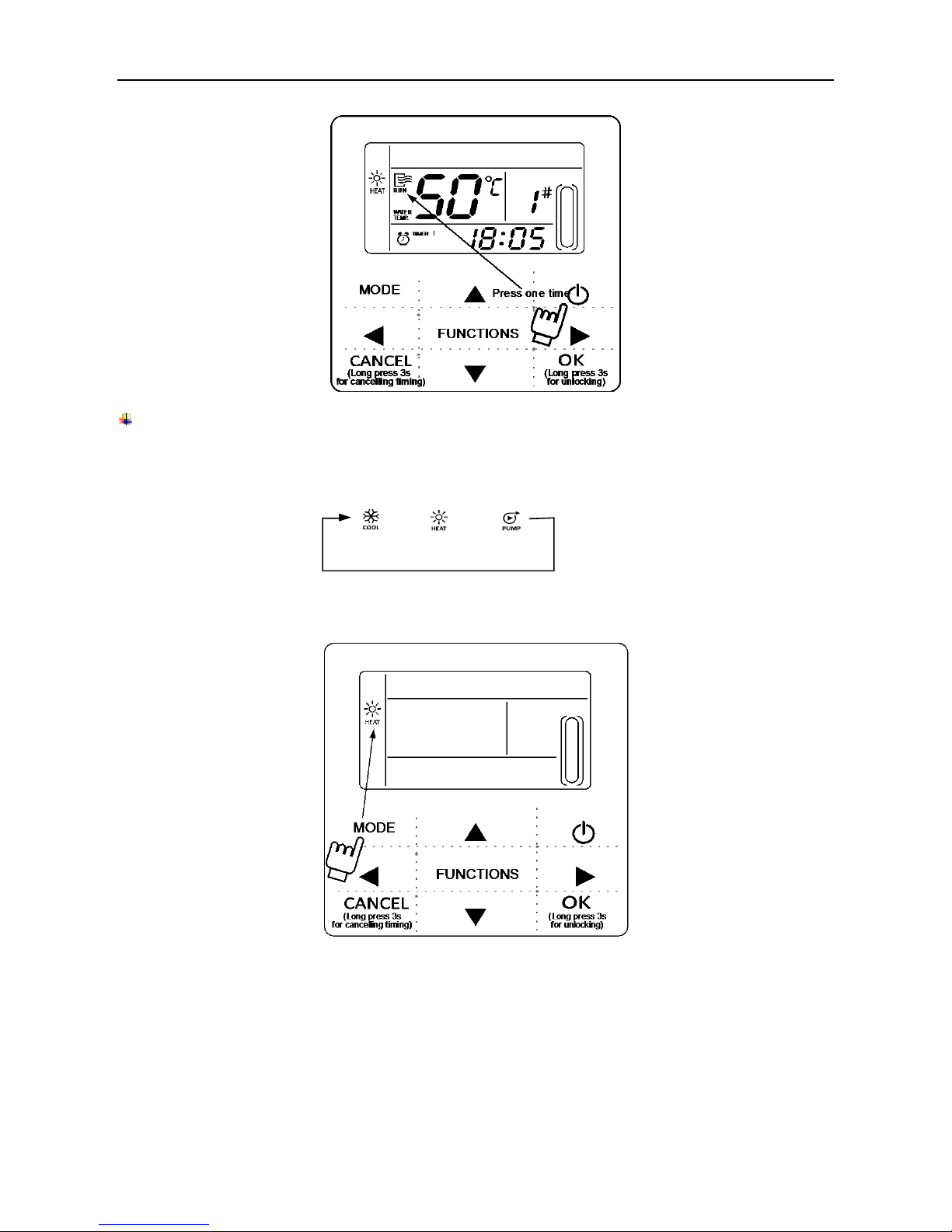
1.1.3 Operation instruction
On and Off the main unit
1) Press the On/Off key to control On and Off status of the main unit.
2) Under Off status, press the On/Off key to operate the main unit, at that time the LCD of wired
controller will display the operation icon . The main unit will be operated as the current setting of the
wired controller.
3) Under On status, press the On/Off key to off the main unit, at that time the operation icon ― on
the LCD of wired controller will disappear.
Note:
1. When outdoor unit is in restore-to-factory-default setting mode (outdoor unit displays ―OFF‖), wired
controller won‘t start the unit. Quit ―OFF‖ status through outdoor unit display operation panel.
2. If outdoor unit is forced shutdown by remote control, then the unit won‘t start by using wired controller.
Relieve the unit from shutdown status by remote control.
Chiller wired controller
Operating mode setting
Press ―MODE‖ key to choose operation mode. The setting mode will change as the following order each
time the key is pressed:
Press ―OK‖ key or wait for 7 seconds to confirm. During the setting process, pressing the ―CANCEL‖ key
to exit without saving.
→
→

Chiller wired controller
Setting water temperature:
Method 1:
Press the ▲ or ▼ to adjust the water temperature under main interface. Press OK key or wait for 7
seconds to confirm.
Method 2:
Setting water temperature in function parameter: Press FUNCTIONS key under main interface once to
enter water temperature setting interface. Press the ▲ or ▼ to adjust the water temperature .Press OK
key or wait for 7 seconds to confirm.
Water temperature setting check: To check the water temperature setting value, press the ◄ or ► key
under the main page (the page displayed after the controller is powered on).
Function parameters setting
Press FUNCTIONS key to choose operation parameters. The setting function parameters will change as
the following order each time the key is pressed:
→
→
W
ater temp. setting
T
iming
Clock
Unit NO.
→
W
ater pump forced
→
Chiller wired controller
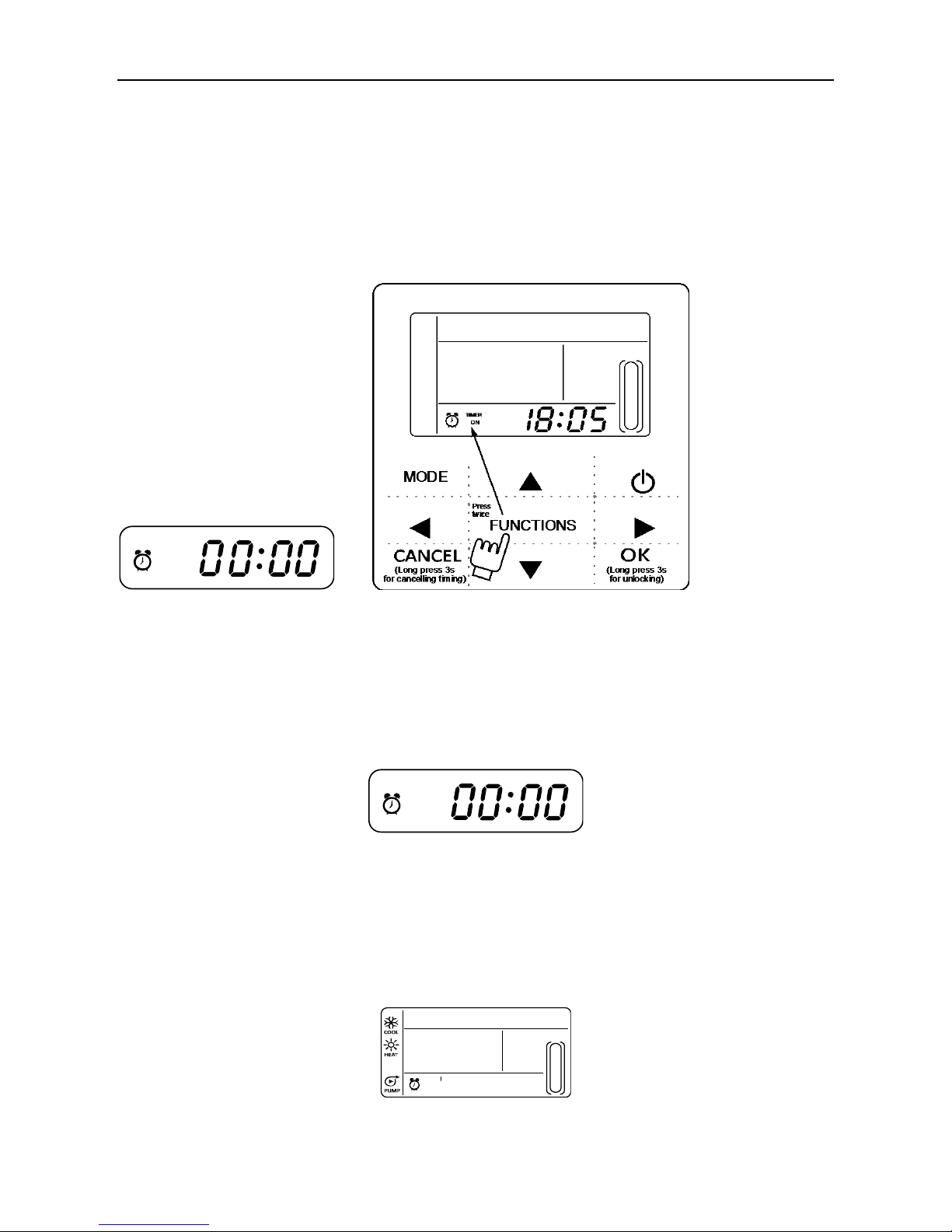
1. Timer setting:
3 timing periods can be set on the wire controller: Timer 1, Timer 2, and Timer 3. These 3 timers can
control the main unit to be turned ON and OFF 3 times at most during a day.
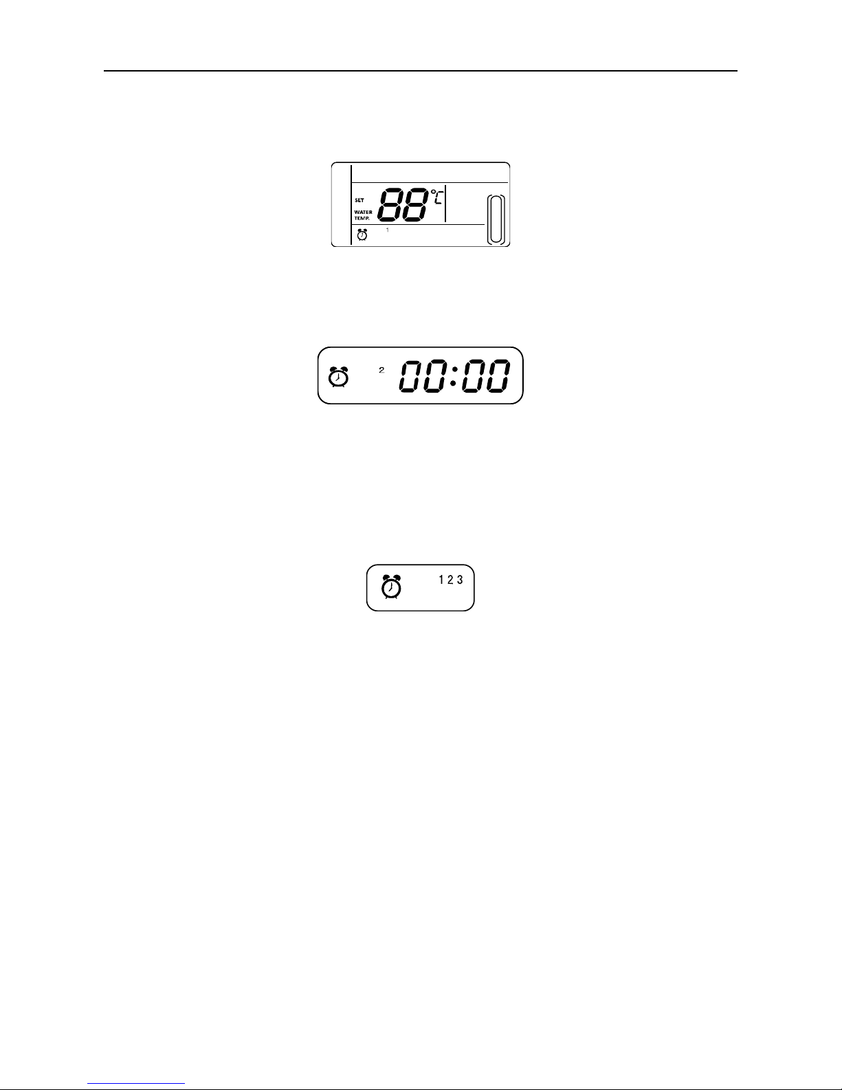
Setting method: press ―FUNCTIONS‖ key under main page twice to enter timing setting. Then the LCD
will display as the following:
2. At this time the hour of the clock will flash, which means the current setting is the hour of Timer 1 ―On‖,
press the ▲ or ▼ to adjust, press ► key when finished, and then the minute of the clock will flash,
which means the current setting is the minute of Timer 1 ―On‖, press the ▲ or ▼ to adjust, press ►
key when finished, the LCD will display as the following:
3. At this time the hour of the clock will flash, which means the current setting is the hour of Timer 1 ―Off‖,
press the ▲ or ▼ to adjust, press ► key when finished, and then the minute of the clock will flash, which
means the current setting is the minute of Timing 1 ―Off‖, press the ▲ or ▼ to adjust, press ► key when
finished, the LCD will display as the following:
1
TIMER
ON
1
TIMER
OFF
TIMER
Chiller wired controller
4. At this time the mode icon will flash, it means the current setting is the running mode in the Timer 1 ,
press the ▲ or ▼to adjust, press ► key when finished, the LCD will display as the following:
5. At this time the water temperature icon will flash, it means the current setting is the water temperature,
press the ▲ or ▼ to adjust, press ► key when finished, the LCD will display as the following:
6. At this time the hour of the clock will flash, it means the current setting is the hour of the Timer 2 ―On‖.
And the follow setting method will be the same as the Timer 1. Similarly, the setting of Timing 3 is the
same as this method. After setting is finished, press ―OK‖ key or wait for 7 seconds to confirm the setting,
and the LCD will display the effective timing information, as the following display:
TIMER
TIMER
ON
TIMER

Chiller wired controller
7. Example of Timing setting:
During any period of timing setting to press ―OK‖ key , the timing periods which have been set will be
effective (only if the ―On‖ and ―Off‖ of one timing period have been set, the setting is effective).
Yes
No
Yes
No
Main page
▼
Press ―FUNCTIONS‖ key twice to enter hour
setting interface of ―Timer 1 On‖
▼
▼
▼
Press ― ‖ key to enter minute setting interface of
―Timer 1 On‖, adjust the minute number to be 10
Press ― ‖ key to enter hour setting interface of ―Timer
1 Off ‖, adjust the hour number of ―Timer 1 Off‖ to be 12
Press the ―▲‖ or ―▼‖ key to set the hour
number of ―Timing 1 On‖ to be 07
Press ― ‖ key to enter minute setting interface of
―Timer 1 Off‖, adjust the minute number to be 30
The setting steps of ―Timer 2‖ and ―Timer 3‖ are the same as ―Timer 1‖, after
setting all the settings then press ―OK‖ key, the 3 timing periods will be effective.
―Timer 1‖ setting
finished, after 7
seconds, the
page shift to the
main page.
Successfully set the On time of ―Timer 1‖ to
be 07:10 and Off time of ―Timer 1 Off ‖ to be
12:30. In this time period to run heating
mode. Then back to the main page.
Finish setting the ―Timer 1‖ , then
enter the setting of ―Timer 2‖.
Whether press ―OK‖ key
Whether press ― ‖ key
▼
Press ― ‖ key to enter running mode etting,adjust
the mode to be ―HEAT‖
▼
Press ― ‖ key to enter water temp. setting , adjust
the temp. to be 45℃.

Chiller wired controller
Check timing information: to check the timing which has been set, press◄ or ► key under main page, the
―On‖ and ―Off‖ time of Timer1, Timer 2 and Timer3 will be displayed in turns.
Cancel timing:
Press ―CANCEL‖ key for 3 seconds, then all the effective timing periods will be cancelled.
Notes:
1. To avoid timing error, each period of timing should not be crossed. E.g.:
2. Once timer on works, the unit will run as the timer on set mode and set water temperature.
3. When timing on and timing off work at the same time, wire control execution timing off.
Clock setting
Press the FUNCTIONS key 3 times to enter clock setting. The hour of the clock will flash, which means
the current setting is the hour of the clock, press the ▲ or ▼ to adjust, press ► key when finished, and
then the minute of the clock will flash, it means the current setting is the minute of the clock, press the
▲or ▼ to adjust, press OK key when finished or wait for 7 seconds to confirm. During the setting process,
pressing the CANCEL key to exit without saving.
Note:
To get the correct timing On and timing Off time, please correctly set the clock!
5:00
8:00
10:00 12:00
18:00
22:00
8:00
7:00
12:00
Correct:
Wrong:
TIMER 1
TIMER 2TIMER 1
TIMER 2
TIMER 3

Chiller wired controller
Unit number setting
Press the FUNCTIONS key 4 times to enter the unit number setting. Press ▲ or ▼ to adjust the unit
number. Press OK key when finished or wait for 7 seconds to confirm. During the setting process,
pressing the CANCEL key to exit without saving. The setting value is 0-19.
Forced open water pump
Press the FUNCTIONS key 5 times to force open the water pump. The water pump icon will flash.
Press OK key to confirm. During the setting process pressing the CANCEL key to return to the main
interface, and log off the forced water pump mode.
Notes:
a. Forcing water pump function is only limited to stand-by mode, others modes not response.
b. Under forcing water pump function, other settings will not responsible, except stopping
c. When communication disconnects, it will show E2 error in 2 minutes, the wired controller will
automatically cancel the forcing water pump function; while connected, the wired controller keeps
Chiller wired controller
synchronizing with the unit( If forcing water pump function is still on-going, the controller keeping showing
its status).
d. The outdoor unit does not response after activating the forcing water pump function,
(e.g.: forcing water pump function cannot be activated under forcing heating in stand-by mode), the
function will be automatically stopped if it is not activated within 5 minutes.
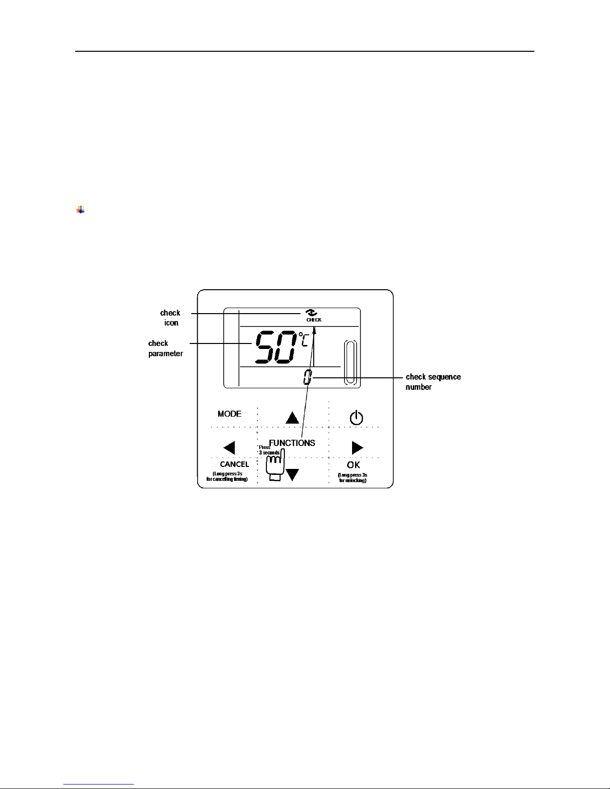
Check function
1) Check function allows the user to check all the operating parameters, error and protection information
of the unit.
2) Enter method: press FUNCTIONS key for 3 seconds to enter check interface, as the figure display:
3) Press
◄ or ►
key to check all the status information of the unit.

Chiller wired controller
Check content
NO.
Description
0
When in standby mode, water pump mode, displays water inlet temperature.
In cooling and heating mode, displays the operating frequency.
When defrosting, displays dF; When anti-freezing, displays Pb.
When oil returning, displays d0; When remote controlling displays d8.
1
Running model: 0-shutdown, 1-Pump mode, 2-Cooling, 3-Heating, 4-Forced cooling,
5-Forced heating.
2
Fan speed: 0-Shutdown, 1~7-Fan speed.
3
Total capacity requirements.
4
The revised capacity requirements.
5
Cooling/heating temperature setting.
6
Condenser temp. Value.(T3)
7
Outdoor ambient temp. Value.(T4)
8
Comp. Discharge temp. Value.(Tp)
9
Inlet water temp. Value.(Tin)
10
Outlet water temp. Value.(Tout)
11
Plate heat exchanger anti-freezing temp. Value 1.(Tb1 )
12
Plate heat exchanger anti-freezing temp. Value 2.(Tb2 )
13
T6 temp. Value(Reserved )
14
Outdoor unit current
15
Power supply voltage AD value
16
Electronic expansion valve opening steps
17
The unit model
18
The program version number
19
The last error record
20
The second error record
21
The first error record
22
─ ─

Chiller wired controller
When the unit has error or protection, icon will flash. If the ―error‖ icon is on, it means the
corresponding unit has error or protection at that time. The last 3 error or protection codes of the unit can
be checked. The error icon will disappear if the error or protection is cleared.
Code
Description
Code
Description
EE
EEPROM error code(Wired controller)
CP
Anti-idling protection of water pump
E9
EEPROM malfunction
F7
Tb1 temperature sensor malfunction
EA
Fan error in A region last for more than 5
minutes in heating mode
F8
Tb2 temperature sensor malfunction
Eb
Two times of E6 protection in 10 minutes
P1
High pressure protection
E4
T3&T4 temperature sensor malfunction
P2
Low pressure protection
E5
Voltage protection
P3
Outdoor units current protection
E6
DC fan motor malfunction
P4
Compressor discharge temp. Protection
H0
Communication malfunction between the
main control chip and IPDU
P5
Condenser high temperature protection
C0
Tin temperature sensor malfunction
P6
IPM mode protection
C1
Tout temperature sensor malfunction
P8
Typhoon protection
C8
Flow switch malfunction
Pb
Outdoor units anti-freezing protection
CH
High temperature protection in heating
mode
PL
Radiator high temperature protection
CL
Low temperature protection in heating
mode
PH
Water inlet and outlet temp. difference
too large protection
Error handling
Chiller wired controller
1.1.4 Installation instruction
Circuit of wired controller is the low voltage circuit. Never connect it with a standard 220V/380V circuit
or put it into a same Wiring Tube with the circuit.
The shield cable must be connected stable to the ground, or transmission may fail.
Do not attempt to extend the shield cable by cutting, if it is necessary, use Terminal Connection Block
to connect.
After finishing connection, do not use Megger to have the insulation check to the signal wire.
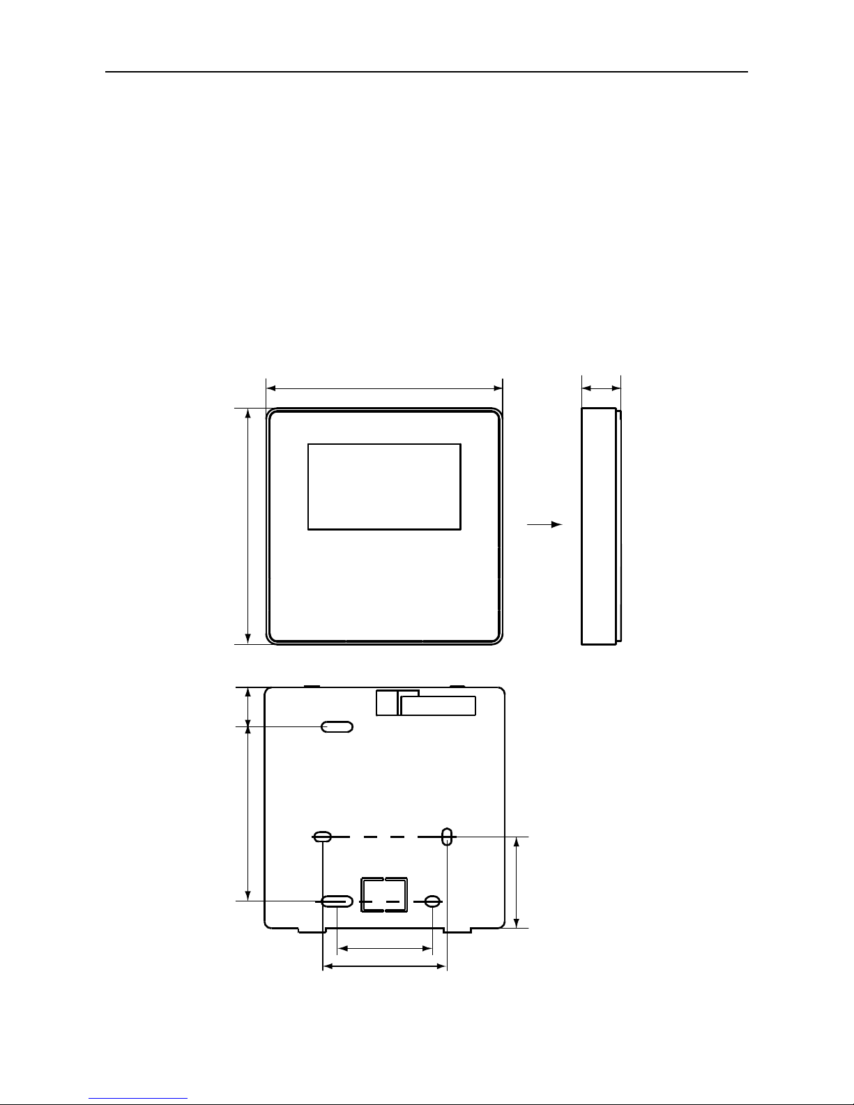
1. Structure size: 120*120*20mm
19mm84mm
44mm
46mm
60mm
120mm 20mm
120mm
Figure A

Chiller wired controller
2. Wiring sketch
3. Wiring figure
1) During installation, make sure correctly wiring the 5 wiring terminals of the wire controller: A, B
connect to output terminal of adapter; P, Q, E should connect to the P, Q, E terminals of the wiring socket
in the electric control box through 3-core shielded wire.
2) The tightening torque range of screw is: 0.8~1.2N • m (8~12 kgf • cm).
3-core shielding wire
AC22OV

Chiller wired controller
4. Back cover installation
1) Use straight head screwdriver to insert into the buckling position in the bottom of wire controller, and
spin the screwdriver to take down the back cover. (Pay attention to spinning direction, otherwise will
damage the back cover!)
2) Use three GB950-86 M4X20 screws to directly install the back cover on the wall.
3) Use two M4X25 GB823-88screws to install the back cover on the 86 electrician box, and use one
GB950-86 M4X20 screws for fixing on the wall.
Buckling
position
Back cover
Straight head
screwdriver
Front cover
Screw hole installed on the wall,use
three GB950-86 M4X20
Screw hole installed on 86
Electrician box, use two
M4X25 GB823-88
Screw hole fixed on the wall,use
one GB950-86 M4X20

Chiller wired controller
4) Adjust the length of two plastic screw bars in the accessory to be standard length from the electrical
box screw bar to the wall. Make sure when install the screw bar to the electrical box screw bar, make it as
flat as the wall.
5) Use cross head screws to fix the wire controller bottom cover in the electric control box through the
screw bar. Make sure the wire controller bottom cover is on the same level after installation, and then
install the wire controller back to the bottom cover.
6) Over fasten the screw will lead to deformation of back cover.
5. Wiring
1) Wiring, three out letting positions
86
Electrician
box
Back cover
Signal switching
wires
Cutting place of left
down side wire outlet

Chiller wired controller
When under installation, reserve certain length of the connecting wire for convenient to take down the
wired controller while during maintenance.
2) Embedded 86 electrician box wiring
3) Shielded wiring
Left down
side wire
outlet

Chiller wired controller
Avoid the water enter into the wired remote controller, use trap and putty to seal the connectors of wires
during wiring installation.
5. Front cover installation
After adjusting the front cover and then buckle the front cover; avoid clamping the communication
switching wire during installation.
Correct install the back cover and firmly buckle the front cover and back cover, otherwise will make the
front cover drop off.

NOTE CONCERNING PROTECTION OF
ENVIRONMENT
This product must not be disposed of via normal household waste after its service life, but must be
taken to a collection station for the recycling of electrical and electronic devices. The symbol on the
product, the operating instructions or the packaging indicate such disposal procedures. The materials
are recyclable in accordance with their respective symbols. By means of re-use, material recycling or
any other form of recycling old appliances you are making an important contribution to the protection
of our environment. Please ask your local council where your nearest disposal station is located.
-
In case of quality problem or other please contact your local supplier or authorized service center.
Emergency number: 112
PRODUCER
SINCLAIR CORPORATION Ltd.
1-4 Argyll St.
London W1F 7LD
Great Britain
www.sinclair-world.com
This product was manufactured in China (Made in China).
REPRESENTATIVE
SINCLAIR EUROPE spol. s r.o.
Purkynova 45
612 00 Brno
Czech Republic
TECHNICAL SUPPORT
NEPA spol. s r.o.
Purkynova 45
612 00 Brno
Czech Republic
Tel.: +420 800 100 285
Fax: +420 541 590 124
www.sinclair-solutions.com
info@sinclair solutions.com
 Loading...