

Page 1
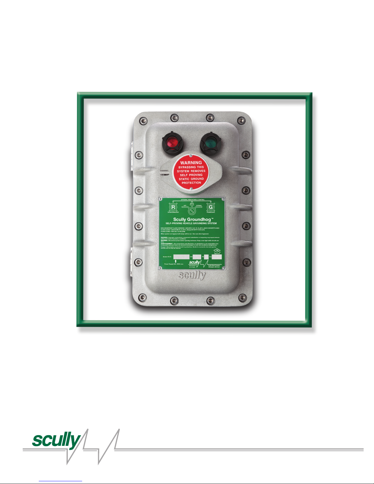
Scully ST-47 Groundhog
Technical Manual
ST-47 Series Self-Proving Vehicle
Grounding Verication System
MaxSafety
SYSTEMS
®
Scully Signal Company / Tel. 617 692 8600 / Fax. 617 692 8620 / 800 2 SCULLY (272 8559)
70 Industrial Way, Wilmington, MA 01887-3479, USA
Page 2

Page 3

ST-47 Groundhog - Technical Manual
Table of Contents
General 5.
1.1 Purpose of Equipment
1.2 ST-47 Normal Operation
Technical Specications & Approvals 9.
2.1 Input Power
2.2 Control Contact
2.3 Operating Temperature
2.4 FM Approval & FM Approval for Canada
Installation 10.
3.1 Enclosure
3.2 Physical Location
3.3 Electrical Installation
3.4 Ground Ball Installation- Stand Alone Applications
3.5 Ground Bolt Installation- Combined with Rack Monitor
Initial System Checkout 11.
4.1 General
4.2 Models Without Bypass Switch
4.3 Models With Bypass Switch
4.4 Models With Deadman Feature
Servicing The ST-47 12.
5.1 General
5.2 Replacing Indicator Lamps
5.3 Tools & Test Equipment Required for Servicing
5.4 Test Procedure 1- Wire-Through Applications Only
5.5 Test Procedure 2- Stand Alone Applications Only
5.6 Troubleshooting Models With Deadman Capability
Page 4

ST-47 Groundhog - Technical Manual
Table of Contents
Diagram Appendix
6.1 DWG 61655 – Installation Drawing with Entity Parameters
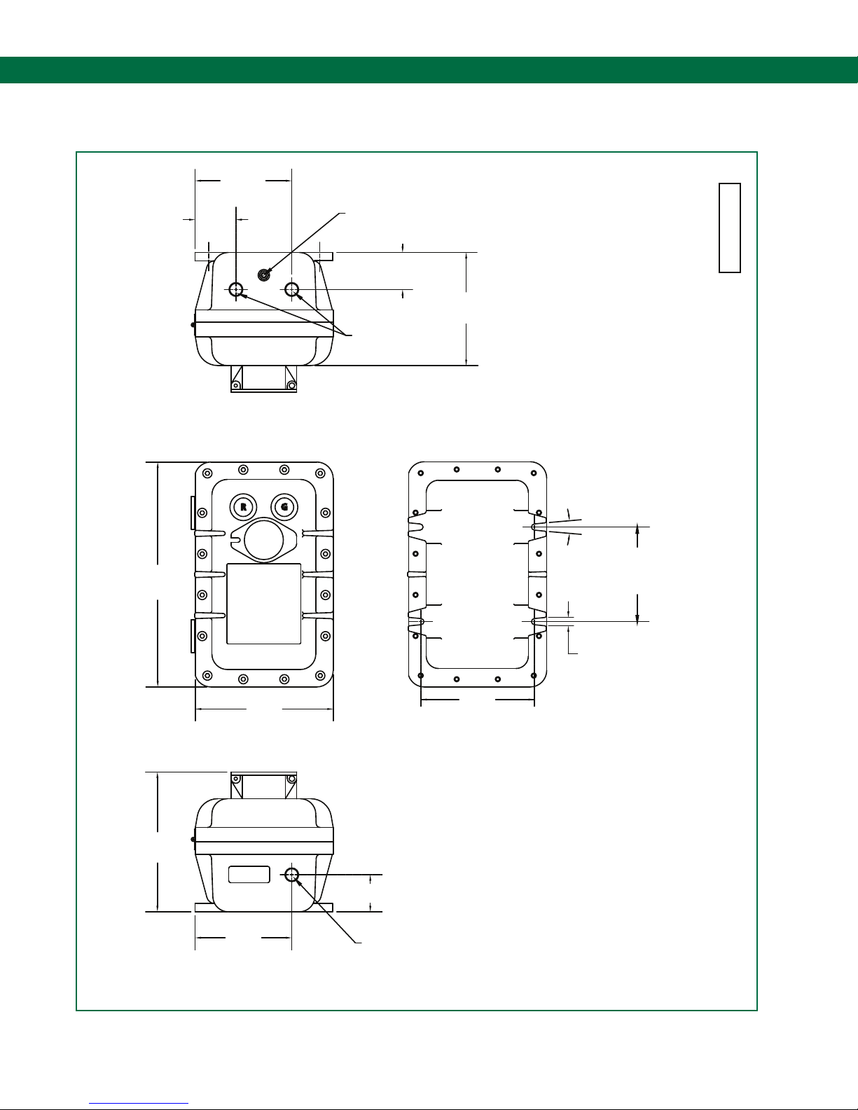
6.2 DWG 31412 – Outline Drawing – Control Unit Enclosure 18.
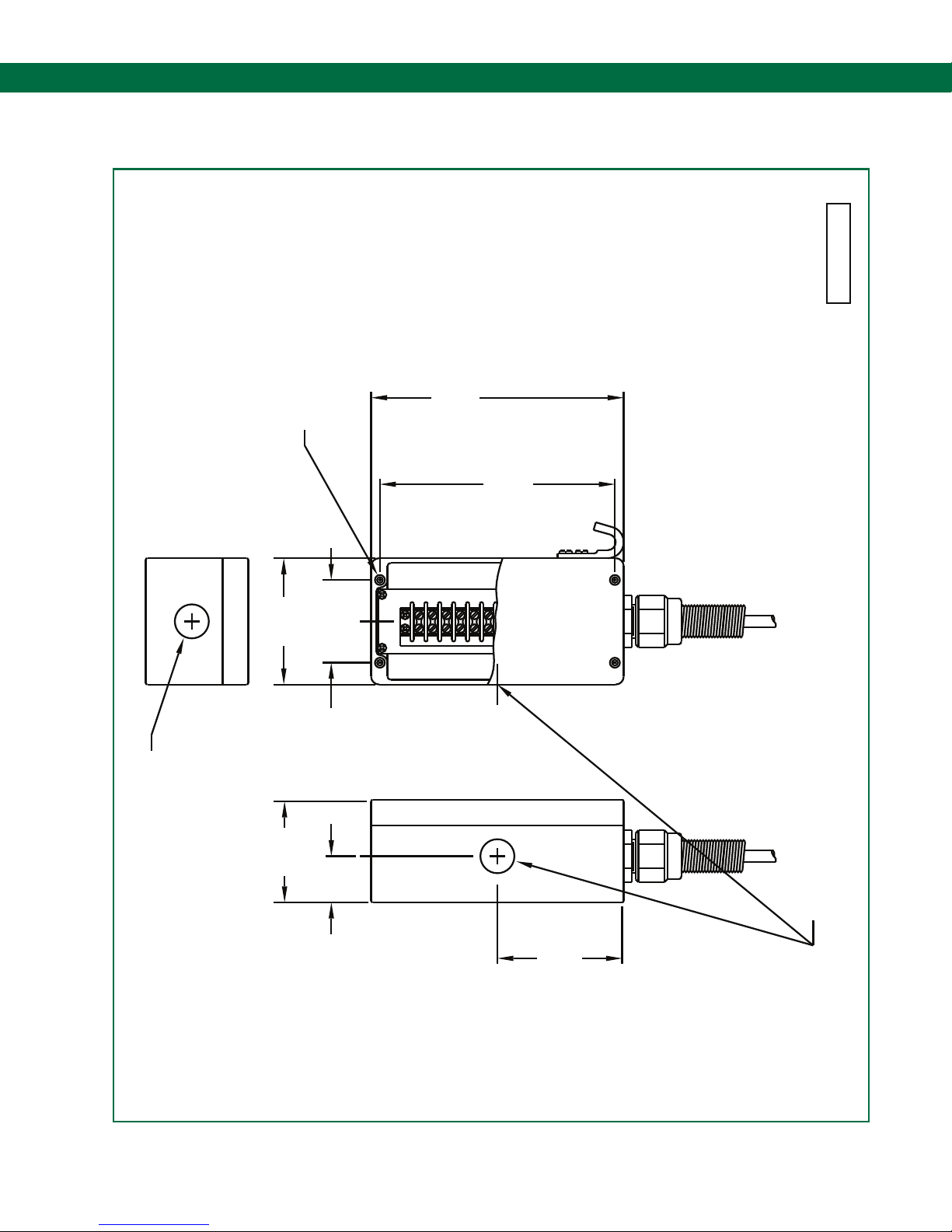
6.3 DWG 63039 – Outline Drawing – Sculcon Junction Box 19.
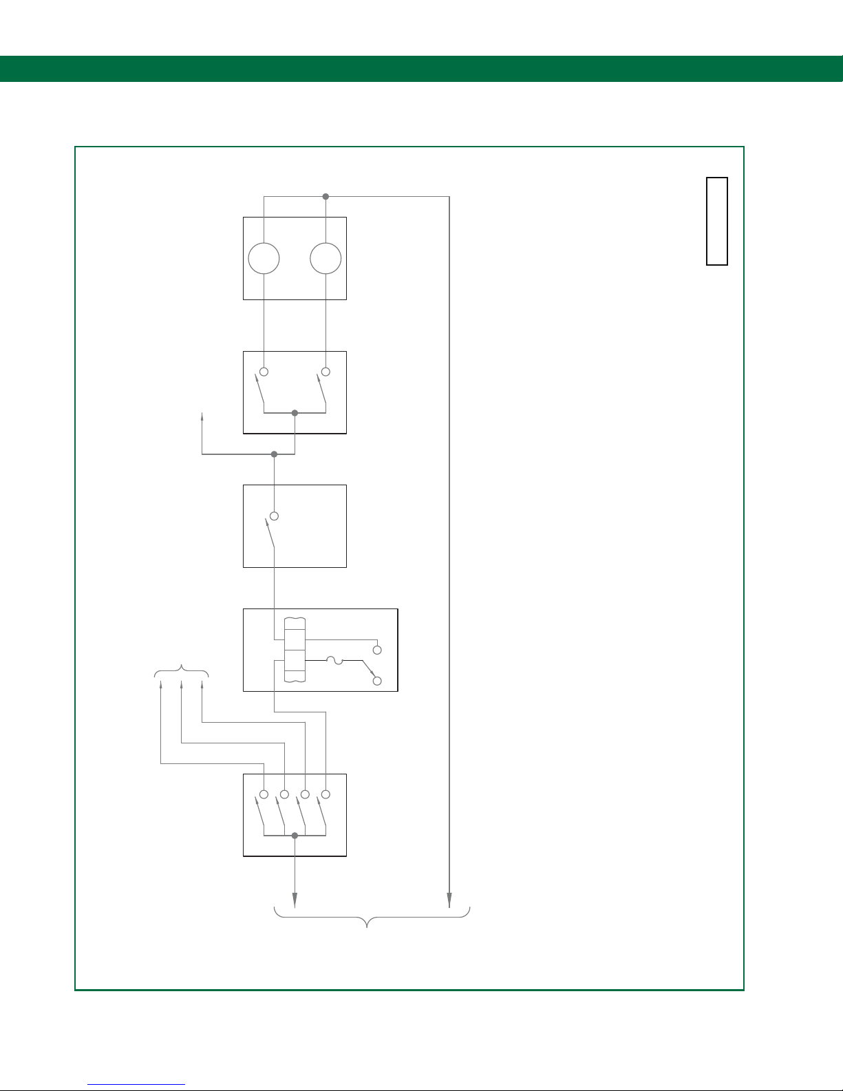
6.4 DWG 61441 – Wiring Diagram – Typical Loading Rack Control 20.
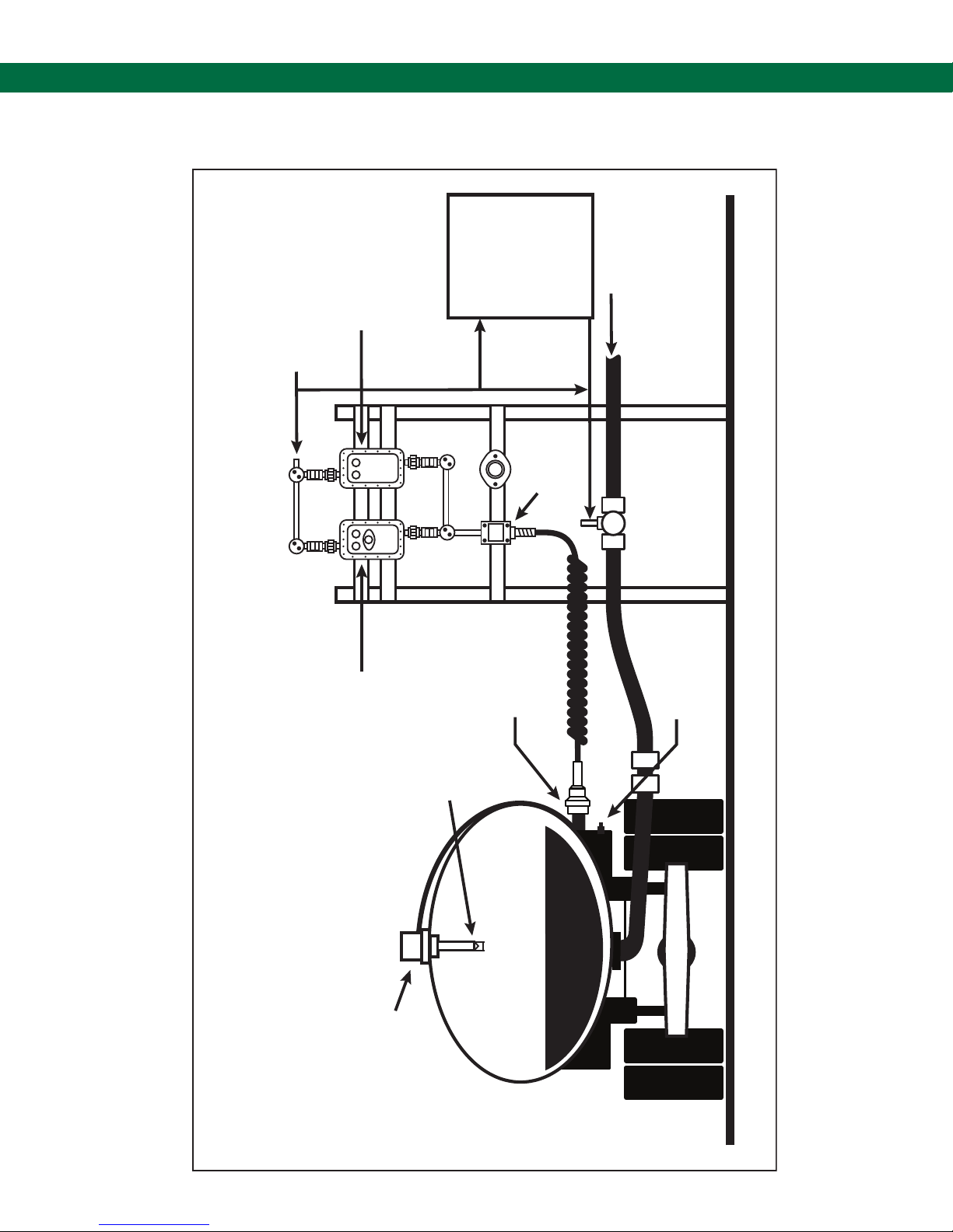
6.5 DWG 61345 – Principle of Overll Prevention & Grounding 21.
6.6 DWG 61346 – Grounding Protection for Product Loading & Ofoading
6.7 DWG 61442 – Mounting Diagram – Control Unit & Junction Box 23.
6.8 DWG 61334 – Internal Wiring Diagram ST-47-EL 24.
6.9 DWG 61333 – Internal Wiring Diagram ST-47-ELK 25.
6.10 DWG 61331 – Internal Wiring Diagram ST-47-EL/D 26.
6.11 DWG 61332 – Internal Wiring Diagram ST-47-ELK/D 27.
6.12 DWG 61121 – Field Wiring Diagram ST-47-115/240 EL(K) 28.
6.13 DWG 61099 – Field Wiring Diagram ST-35/ST-47 29.
6.14 DWG 61098 – Field Wiring Diagram ST-15/ST-47 30.
6.15 DWG 61141 – Field Wiring Diagram ST-47-115 EL(K)D 31.
17.
22.
6.16 DWG 61168 – Field Wiring Diagram ST-15-ELK/D & ST-47
6.17 DWG 61167 – Field Wiring Diagram ST-15-ELK/D & ST-47 33.
6.18 DWG 61169 – Field Wiring Diagram ST-35-ELK/D & ST-47 34.
6.19 DWG 61202 – Replacement Parts for ST-47-115 35.
6.20 DWG 61273 – Replacement Parts for ST-47-240 36.
32.
Page 5

Self-Proving Vehicle Grounding Verication System
General
1.1 Purpose Of Equipment
The ST-47 Groundhog is a line powered, Self- Proving, Vehicle Ground Verication System. It may
be used to insure a safe ground between a terminal loading rack and a tank vehicle which is in the
process of loading or unloading a hazardous product. The Groundhog system can be used in one
of three modes: 1.) Wire-Through, 2.) Stand -Alone, 3.) Non Self-Proving. Optional front cover
lamps indicate grounded (green lamp on) or non-grounded (red lamp on) status. Intrinsically safe
ground verication signals connect to TB2 terminals 2 (ground) and 3 (proving signal) in modes 1
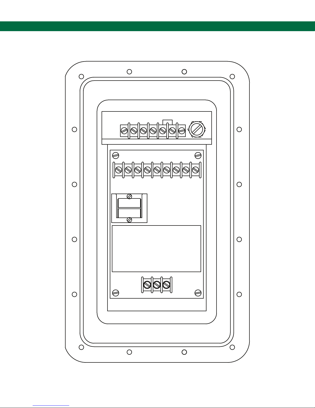
and 2. Refer to Figure 1.2 for ST-47 Terminal Block (TB) locations.
1.1.1 Wire-Through Mode Description
In the Wire-Through conguration, the ST-47 control monitor is ideally mounted near a new, or
existing, Scully overll prevention monitor (see Appendix for appropriate interconnection wiring
diagram). When the two monitors are located in close proximity, vehicle drivers or loader personnel
can easily view the status lamps.
Two wires from the ST-47 I.S. terminals connect to the new, or existing, overll prevention cable
junction box. A single Scully Ground Bolt, mounted on a tank vehicle (or other container), serves as
the truck ground verication point. The system is self-proving when the overll prevention plug is
connected to the vehicle mounted Ground Bolt (P/N 08560) through socket pin no. 9.
A time-varying intrinsically safe voltage is sent out on ST-47 TB2 terminal 3. With the Scully overll
protection plug connected to the vehicle mounted overll system socket, a ground connection is
established through pin 10 of the socket to the chassis of the vehicle. The ground proving signal
enters the socket through pin 9. The Ground Bolt is required to complete the circuit in the ST-47
controller. The circuit is completed through pin 9, through the green wire, through the Ground Bolt,
to the chassis of the vehicle or equipment, through pin 10 and back to the ground connection, TB2
terminal, at the controller. If the control monitor senses a complete signal path, it will close its
“permissive” contact. The permissive contact is typically used to control a pump, valve, or input to
a Terminal Automation System or Programmable Logic Controller (PLC).
1.1.2 Stand Alone Mode Description
Used in the Stand-Alone mode, the ST-47 Groundhog is typically mounted near the terminal rack
equipment and hard wires to the Scully Model SC-47CC or SC-47CC/D cable junction box. The
cable junction box contains terminals connecting to a special snap-on plug using a 32 foot (ten
meter) coiled or a 20 foot (six meter) straight cable. A single Scully Ground Ball mounted on a tank
vehicle serves as the truck ground verication point. The system is self-proving when the snap-on
plug is connected to the vehicle mounted Ground Ball. When connected, the ST-47 sends a
time-varying intrinsically safe voltage from TB2 terminal 3 to the top of the two piece Ground Ball
and through the frame of the vehicle. The ball returns a portion of the signal to the control monitor
TB2 terminal 2 through its base. If the control monitor senses this signal, it will close its
“permissive” contact. The permissive contact is typically used to control a pump, valve, or input
to a Terminal Automation System.
Page 5.
Page 6
ST-47 Groundhog - Technical Manual
General
1.1.3 Deadman Capable Model Description
(Applies to Models ST-47 EL(K)/D) Deadman capable models of the ST-47 differ from standard
models in two ways
1.) The Model ST-47/D requires the use of a Scully deadman equipped plug and cable or
ground ball connector and cable assemblies (Model SC-47CC/D). These include a
hand-operated deadman switch added to a standard plug and cable assembly.
Two additional wires must be run in the intrinsically Safe (I.S.) conduit which connects the
ST-47/D to the plug and cable assembly.
2.) Unlike the standard Model ST-47 there is no volt free permissive contact connected to
TB1 terminals 4 and 5. Only the permissive contact of TB1 terminal 5 can be utilized and it
must be connected to one wire (AC hot) of an inductive or resistive external device. The
other wire of the inductive or resistive external device is connected to AC neutral. In normal
operation, the deadman switch must be operated to “permit” operation of the external
device. When the ST-47 is permissive (green lamp lit), and the deadman switch is operated,
the external device connected to TB1 terminal 5 is energized.
1.2 ST-47 Normal Operation
1.2.1 Status Lamps
Match the state of the front cover indicators on the Groundhog with the chart below. Determine if
the status meets the conditions present and refer to the Troubleshooting Section of this manual if
required.
LAMP STATUS
RED INDICATION
OFF ON Rack to vehicle, rail tank car, container, etc. ground bond veried.
Output is “Permissive”
ON OFF Rack to vehicle, rail tank car, container, etc. ground bond not veried or unit is
malfunctioning. Output is “Non-Permissive”
OFF OFF 1.) Indicator lamp(s) is/are burned out.
2.) The unit is not powered.
3.) Optional Bypass switch is in OFF or BYPASS position.
1.2.2 Use With Scully Ground Bolt or Ground Ball
A front panel mounted red lamp indicates that a safe ground attachment has not been made or,
the ST-47 is not connected to a vehicle. After connection to a vehicle mounted Ground Ball or
Ground Bolt the green lamp on the front panel illuminates indicating that the Scully Groundhog
system is operational and the ground path to the vehicle is complete. A normally open user contact
is provided on TB1 terminals 4 and 5, it should be connected to the permit circuitry at the terminal
loading rack. The permit contacts close when the ground path to the vehicle is veried.
GREEN
Page 6.
Page 7
Self-Proving Vehicle Grounding Verication System
General
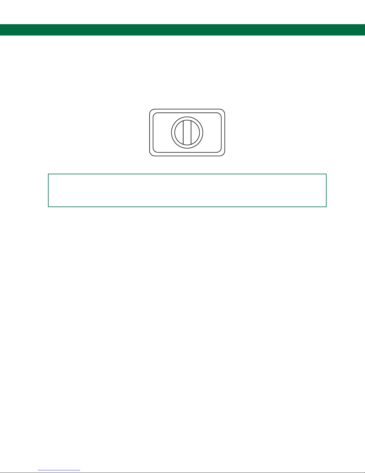
1.2.3 Optional Bypass Switch-Models ST-47-115 or 240 ELK
An optional, three position switch, is mounted on the front cover. It allows the system to operate
normally in the AUTO (center position), turned OFF (left most position), or placed in BYPASS (right
most position). In the Bypass mode, the user contact will “permit” but, both the red and green
lamps will be extinguished.
OFF AUTO BYPASS
Figure 1.1 Bypass Switch Illustration (Shown in AUTO Position)
WARNING
With the OFF/ AUTO/ BYPASS Switch in the BYPASS Position,
THERE IS NO GROUND VERIFICATION PROTECTION.
1.2.4 Optional Deadman Capability-Models ST-47-115 or 240 EL(K)/D
1.2.4.1 Permissive Contact Connection to External Devices
Terminal 4 of TB1 is factory connected to the “hot” side of the AC power line. This factory installed
jumper connecting TB1 terminals 3 and 4 can be removed if the end-user must isolate the
permissive terminals. Do not exceed the following values for the permissive terminal input and
output.
Operating and Load Voltage Range..........95 to 135 VAC
Load Current Maximum............................5 Amperes resistive
If connection is made to an external device which is neither resistive nor inductive, an interposing
relay must be used. One example of this type of external device requiring an interposing relay is a
Programmable Logic Controller (PLC). When using a relay, connect one wire of the device to TB1
terminal 5 and the other wire to AC neutral. In most instances a normally open contact of the relay
is used. One “Common” contact should make connection to whatever voltage is required by the
device to be activated. When the ST-47 is permissive, the interposing relay will energize, and
operate an external device or devices.
1.2.4.2 Deadman Switch Connection to the ST-47
Two wires (black and white) are factory connected from the Deadman switch to terminals 1 and 2
inside the Scully plug and cable box. Applicable junction boxes may be identied by the “/D” in
their Model designation. The end-user must provide wiring which connects the two terminals to
TB3 inside (bottom) of the ST-47 explosion proof housing.
Page 7.
Page 8
ST-47 Groundhog - Technical Manual
General
TB1
MAINS POWER
GND
1
2
NEUT HOT
3
4
CONTROL CONTACTS
RATED 5 AMPS
250 Volts MAX
(TB1)
5
FUSE
Size: 3AG
250 - 5A
[ ]
“SLO - BLO”
8 9
7
6
Figure 1.2 ST-47 Terminal Block Location Illustration
Page 8.
TB2
1
2
3
Page 9
Self-Proving Vehicle Grounding Verication System
Technical Specications and Approvals
2.1 Input Power
120 VAC +/- 15% or 208-240 VAC 50/60Hz
.25 Amps Maximum .125 Amps Maximum
2.2 Control Contact
Independently fused, 240 VAC
5 Amps resistive
2.3 Operating Temperature
-40 to +158 deg. F
(-40 to +70 deg. C)
2.4 FM Approval & FM Approval for Canada
This system’s outputs have been FM Approved as Intrinsically Safe for
Connection to Class I, Division 1, Groups C and D Hazardous Locations.
The Ground Ball or Ground Bolt may be mounted in a Class I, Division 1, Group C or D
Hazardous Location.
The ST-47-115 EL(K) and ST-47-240 EL(K) may be mounted in a Class I, Division 1, Group C or D
Hazardous Location.
Page 9.
Page 10

ST-47 Groundhog - Technical Manual
Installation
3.1 Enclosure
The ST-47 is mounted in a NEMA 7 style explosion proof & weather proof enclosure that is typically
located near other rack equipment. Refer to typical loading rack installation for suggested
mounting.
3.2 Physical Location
a.) The front panel must be in the vertical position.
b.) The hinged front cover must be able to swing open for ease of servicing and chassis removal.
c.) The front panel indicators must be visible to the loader.
3.3 Electrical Installation
CAUTION
Keep the Intrinsically Safe Wiring SEPARATE from any Power
and Control Circuit Wiring by Running them in Separate Conduits.
No Wiring Should be Allowed to Pass Through from Top to Bottom
of the ST-47 Enclosure.
Systems using an ST-47 controller are wired as shown on an appropriate diagram in the appendix.
3.4 Ground Ball Installation - Stand Alone Applications
Refer to installations packed with Ground Ball, Scully Drawing No.61067.
3.5 Ground Bolt Installation - Combined with Rack Monitor
Refer to installations packed with Ground Bolt, Scully Drawing No.61081.
Page 10.
Page 11

Self-Proving Vehicle Grounding Verication System
Initial System Checkout
4.1 General
(Refer to Figure 1.2 for Terminal Block & Fuse Locations)
Note: All Tests are done with line power applied to the ST-47.
CAUTION
Hazardous Voltages are Present Inside the ST-47 Explosion Proof
Housing. When Working Inside the ST-47 Enclosure Avoid Contact with
the TB1 Terminal Strip at the Top of the Housing
4.2 Models Without Bypass Switch (ST-47- 115 or 240 EL)
Remove all wiring from the I.S. Terminal Strip TB2. You may check operation of the Groundhog by
physically shorting together terminals 1 and 2 on TB2 using a jumper wire. When this test is
performed, the Permit light should illuminate and Permit contacts (TB1 terminals 3 and 4) should
close. When the ST-47 is in the permissive mode any connected devices should activate. If the
connected device does not activate, consult the Troubleshooting section of this manual.
4.3 Models With Bypass Switch (ST-47- 115 or 240 ELK)
Place the Bypass switch in the AUTO position (center position). Remove all wiring from the I.S.
Terminal Strip TB2. You may check operation of the Groundhog by physically shorting together
intrinsically safe terminals 1 and 2 on TB2. When the test is performed, the permit light should
illuminate and the Permit contacts (TB1 terminals 4 and 5) should close. Place switch BYPASS
position (to the right). When the switch is in the Bypass position, power is removed from the ST-47
electronics and the front cover status lamps. Verify that the red and green status lamps are
extinguished and contacts TB1 terminals 4 and 5 are shorted. When the ST-47 is in the permissive
mode any connected devices should activate. If the connected device does not activate consult the
Troubleshooting section of this manual.
4.4 Models With Deadman Feature (ST-47- 115 or 240 EL(K)/D)
4.4.1 Models with Bypass Switch
To test the operation of the deadman switch, the ST-47 must be powered by the line voltage and
the Bypass switch in the AUTO position. When the ST-47 is not connected to a vehicle, rail car,
etc., the Red lamp on the front cover is lit. Connect the plug and cable or clamp to the vehicle to be
grounded. If the vehicle ground is veried the Green lamp on the front cover lights. If the Green
lamp does not light refer to previous sections 4.1 to 4.3.
Operate the deadman handle, the external device connected to the ST-47 permissive output will
activate. When the ST-47 is in the permissive mode any connected devices should activate. If the
connected device does not activate consult the Troubleshooting section of this manual.
4.4.2 Models without Bypass Switch
Perform the test as in paragraph 4.2 by applying power to the ST-47. Applying power is equivalent
to placing the Bypass switch in the AUTO position. When the ST-47 is in the permissive mode any
contact devices should activate. If the connected device does not activate consult the
Troubleshooting section of this manual.
Page 11.
Page 12

ST-47 Groundhog - Technical Manual
Servicing the ST-47
5.1 General
Unless noted otherwise, all the following Procedures are done with power applied to the ST-47. AC
power, as measured on the TB1 terminals 2 (neutral) and 3 hot) must be within the specied
tolerances. If it is not, correct the line voltage problems.
Returning part to Scully for repair or Warranty consideration: Before returning any defective
equipment to the Scully Signal Company for repair and/or Warranty consideration, call Scully at
1.800.272.8559 for an RMA (Return Material Authorization) number.
5.2 Replacing Indicator Lamps
5.2.1 Models with Bypass Switch
Turn off the power to the Groundhog by moving the switch to the far left position. Unscrew the lamp
lens, remove the defective bulb by unscrewing the lamp in the counter-clockwise direction. Insert a
new lamp by reversing the preceding procedure.
Current ST-47-115 models are shipped with LED xtures installed. There are seperate part
numbers for the green replacement LED (09385) and the red replacement LED (09384). Older
models using incandescent lamps can be upgraded by replacing the lamp assembly.
5.2.2 Models without Bypass Switch
Remove the line power from the Groundhog and replace the defective lamp using the procedure in
section 5.2.1.
5.3 Tools & Test Equipment Required for Servicing
5.3.1 Tools
a.) Good quality multi-meter
b.) Flat-blade screwdriver
c.) Two sets of Jumper wires with alligator clips at each end
5.3.2 Required Test Equipment for Wire-Through Mode Operation
Use appropriate equipment from the list below:
a.) Scully Universal Loading Rack Tester, ST-2-DSWJ
b.) Scully Ground Bolt (Part 08560) or Scully Ground Ball (Part 08274)
5.3.3 Required Test Equipment for Stand-Alone Mode Operation
a.) Scully Ground Bolt (Part 08560) or Scully Ground Ball (Part 08274)
Page 12.
Page 13
Self-Proving Vehicle Grounding Verication System
Servicing the ST-47
5.4 Test Procedure 1 - Wire-Through Applications Only
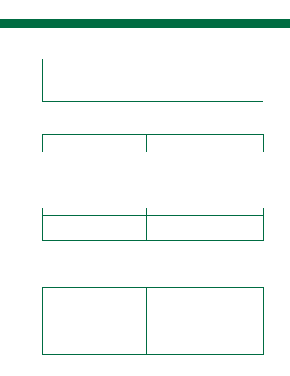
Problem: The overll prevention plug is connected to the tanker mounted overll prevention system
and the RED non-permit lamp stays on. Unit does not “permit” externally connected devices.
TIP
Overll Plug Pin Identication- Orient plug with pins facing you and the
molded-in arrow positioned at 12 o’clock, Pin 1 is located where the
arrow points. Count pins from Pin 1 in a clockwise direction. Pin 9 is in
the center on the left. Pin 10 is in the center on the right
Procedure 1, Step A
Does the tanker have a Scully Ground Bolt installed and wired to Pin 9 of the overll prevention
Socket?
NOYES
Go to the next step Install Ground Bolt on tanker (Scully Part# 08560)
Procedure 1, Step B
If you have a Scully Rack Tester, plug the overll prevention cable into the socket on the tester. If
you do not have a tester but do have a Scully Ground Bolt, use jumper wires to connect the green
wire on the bolt to Pin 9 of the plug and connect the body of the bolt to Pin 10
.
Does the ST-47 Permit?
NOYES
Trailer grounding system is at fault. Have
tanker owner check the installation or,
contact the Scully Service Department for
assistance.
Procedure 1, Step C
Using a Multi-Meter set on DC volts measure the voltage between Pin 9 (+) and Pin 10 (-) of the
overll prevention plug.
Is the voltage between 24 and 30 volts DC?
Go to the next step
Using an open end socket wrench, open the plug
and cable junction box. Remove line power to the
ST-47. Remove wires that come from the cable
and are connected to terminals 9 and 10. Power
the ST-47. Check the voltage at terminals 9 (+)
and 10 (-) on the terminal block found inside. If
you now read 24 and 30 VDC at terminals 9 and
10, there is a problem in the cable or wiring to the
ground ball plug. Correct the problem. If you still
get no voltage reading, go to the next step.
Go to the next step
NOYES
Page 13.
Page 14
ST-47 Groundhog - Technical Manual
Servicing the ST-47
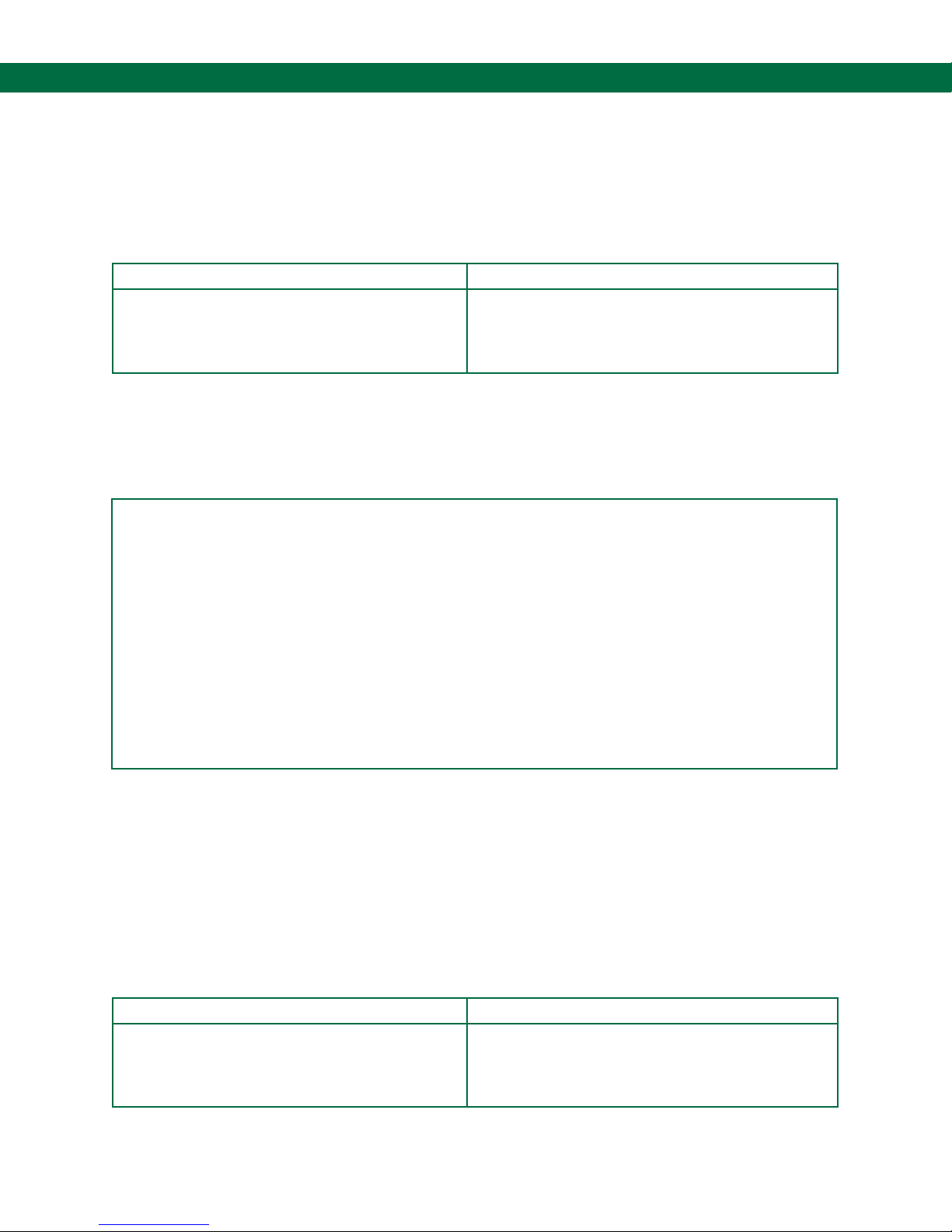
Procedure 1, Step D
Using the correct socket or hex wrench (Depends on ST-47 date of manufacture) remove the cover
fasteners and open the front cover. Using a at-blade screwdriver, remove the wires on intrinsically-
safe terminals TB2-2 and TB2-3. Using a Multi-Meter set on DC volts, measure the DC voltage
between terminals TB2-3 (+) and TB2-2 (-).
Is the voltage between 24 and 30 volts DC?
NOYES
There is a wiring problem between the
ST-47 TB-2 terminals and the Junction Box
terminals. Correct the wiring problem
5.5 Test Procedure 2 - Stand-Alone Applications Only
Problem: The Ground Ball plug is connected to the tanker mounted Scully Ground Verication Ball
and RED non-permit lamp stays on. Unit does not “permit” externally connected devices.
The ST-47 circuit module is defective. Replace
the module with a new one or, return the board
to the Scully Signal Company for repair or
Warranty consideration.
TIP
Ground Ball Connector Plug Maintenance
1.) Spring Finger Tension- Older styles of the Plug used an O-ring to tension the gripping
ngers which grip the base of the Ground Ball. The O-ring has been replaced by a new
tensioning ring (part# 31673) which provides a more positive grip.
2.) Contact Plunger Sticking- Severe weather conditions can cause the stainless steel
contact plunger (at the center, inside the plug) to stick in the down position. If it sticks it will
make a poor connection to the head of the Ground Ball. If it sticks, disassemble the plug and
apply white lube to the plunger where it contacts its plastic housing. To provide good contact
with the ball it must spring in and out freely.
Procedure 2, Step A
This step requires a Scully Ground Bolt or Ground Ball for testing- if you do not have one, Go to
Step A1. Use a jumper wire to connect the green wire on the bolt to the center pin inside of the plug
and connect the body of the bolt to one of the three tension ngers inside the plug. Does the
ST-47 Permit? If you have a Scully Ground Ball, attach the plug to it and touch the green wire to
exposed base of the Ground Ball.
Does the ST-47 Permit?
Trailer grounding system is a fault. Have
tank owner check the installation or, contact
the Scull Service Department for assistance.
Page 14.
NOYES
See TIP on Ground Ball Plug maintenance. If the
plug checks OK, go to procedure 2, Step A1.
Page 15

Self-Proving Vehicle Grounding Verication System
Servicing the ST-47
Procedure 2, Step A1
(Ground Bolt or Ground Ball NOT required) If you do not have a Scully Ground Bolt or Ground Ball.
Using a Multi-Meter set on DC volts measure the voltage between spring plunger contact inside the
plug (+) and one of the three contact ngers (-) of the Ground Ball Connector Plug.
Is the voltage between 24 and 30 volts DC?
NOYES
Trailer grounding system could be at fault.
Have tank owner check the installation or,
contact the Scully Service Department for
assistance.
If the voltage is lower or zero- Using an open
end socket wrench, open the plug and cable
junction box. Remove line power to the ST-47.
Remove wires that come from the cable and are
connected to terminals 9 and 10. Power the
ST-47. Check the voltage at terminals 9 (+) and
10 (-) at the terminal block found inside. Power
the ST-47. If you now read 24 and 30 VDC at
terminals 9 and 10. There is a problem in the
cable or wiring to the overll plug. Correct the
problem. If the voltage is still below limits, go to
step B1.
Procedure 2, Step B
(Ground Bolt required) Using the correct socket or hex wrench (depends on ST-47 date of
manufacture) remove the cover fasteners and open the front cover. Using a at-blade screwdriver,
remove the wires on intrinsically-safe terminals TB2 and 3. Attach the green wire of the Ground Bolt
to TB2-3 and the top of the bolt (at the end of the threads) to TB2-2.
Does the ST-47 Permit?
NOYES
There is a problem between the ST-47 TB-2
terminals and the Junction Box terminals.
Correct the wiring problem.
Procedure 2, Step B1
Using the correct socket or hex wrench (depends on ST-47 date of manufacture) remove the cover
fasteners and open the front cover. Using a at-blade screwdriver, remove the wires on
intrinsically-safe terminals TB2 and 3. Using a Multi-Meter set on DC volts, measure the DC voltage
between terminals TB2-3 (+) and TB2 (-).
Is the voltage between 24 and 30 volts DC?
The ST-47 circuit module is defective. Replace
the module with a new one or, return the board
to the Scully Signal Company for repair or
Warranty consideration.
There is a problem between the ST-47 TB-2
terminals and the Junction Box terminals.
Correct the wiring problem.
NOYES
The ST-47 circuit module is defective. Replace
the module with a new one or, return the board
to the Scully Signal Company for repair or
Warranty consideration.
Page 15.
Page 16

ST-47 Groundhog - Technical Manual
Servicing the ST-47
5.6 Troubleshooting Models with Deadman Capability
5.6.1 General
Before proceeding with this section the ST-47 must be operational. It must permit (green lamp)
when connected to a Scully Ground Ball or Ground Bolt. The unit is capable of turning on the green
permit lamp even if the deadman circuitry is not functioning properly. If the unit will not permit,
consult the earlier parts of this troubleshooting section for advice on repairing the problem.
5.6.2 Wire-Through and Stand-Alone Applications Troubleshooting
Problem: The ST-47 permit lamp comes on but the ST-47 will not activate an external device when
the deadman handle is operated. Turn off the power to the ST-47 by turning the Bypass switch to
the OFF position (if the unit has this option) or turn power off at the source. Using the correct
socket or hex wrench (depends on ST-47 date of manufacture) remove the cover fasteners and
open the front cover. Remove the fuse from its holder which is located at the right end of TB-1 by
turning the top on the right. Remove the now exposed glass fuse from the holder and check it with
a multi-meter set to the Ohms position. Do not rely on a visual inspection as a test for the fuse.
Is the fuse blown?
The external device or wiring to it may be
shorted. Replace fuse, power-up system
and retest. If fuse continues to blow then
check for shorts in the output control wire to
device. Repair the problem, replace the fuse
with one that is the same rating and retest.
NOYES
Replace the fuse in the holder and turn on the
power to the ST-47. With the cover of the ST-47
open, locate TB3 which is the two terminal strip
at the bottom of the explosion proof housing.
Using a jumper wire, short the two terminals
together. If the external device now operates.
There is a problem with the deadman switch or
the wiring to it. Repair the problem. If the ST-47
still does not permit, there could be a problem
with the I.S. Barrier relay that is located on the
inside front cover of unit. Consult the Scully
Service Department.
Page 16.
Page 17
Self-Proving Vehicle Grounding Verication System
Diagram Appendix
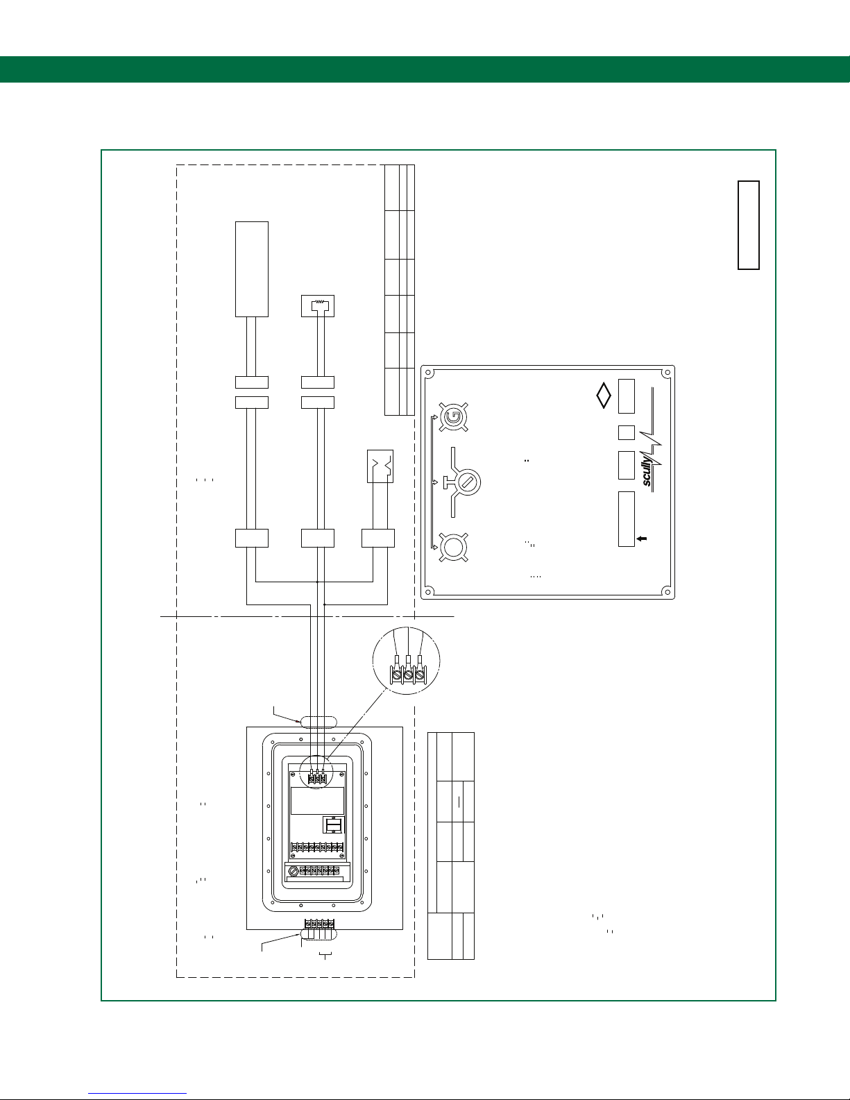
6.1 DWG 61655 – Installation Drawing with Entity Parameters
ALLOWED
La = 200mH
La = 200mH
INDUCTANCE
Ca = 0.070uF
Ca = 0.079uF
ALLOWED
OPTIONAL
OR
RESISTOR
(SIMPLE APPARATUS)
PLUG & SOCKET
POWER CAPACITANCE
MAXIMUM
Isc
TERMINAL Voc
Isc = 14.2mA Po = 105mW
Voc = 29.6V
PINS 3 TO 2
Po = 2.8mW
Isc = 0.4mA
Voc = 28.4V
PINS 2 TO 1
G
PERMISSIVE
TM
GROUND CLAMP
OR
BYPASS
AUTO
OFF
OPTIONAL INDICATORS & CONTROL
CLASS T, DIVISION 1, GROUPS C & D
HAZARDOUS LOCATION
CLASS T, ZONE 0 AEx ia IIB
CLASS T, ZONE 0 Ex ia IIB
OR
(SIMPLE APPARATUS)
SCULLY GROUND BALL
SCULLY GROUND BOLT
PLUG & SOCKET
61655 RevA
USC
FM
Approved
Um
Scully Signal Company
Wilmington, MA USA
YR
'
MaxSafety®SYSTEMS
S/N
HAZARDOUS LOCATION
CLASS T ZONE 1 GROUP IIB,T6, Ta=60°C, AEx[ia] IIB ENTITY 61655 (US)
EXPLOSIONPROOF CLASS T DIVISION 1 GROUPS C & D, T6, Ta=60°C, AIS/I/1/CD/ENTITY-61655
CLASS T ZONE 1 PER CEC 18.100 (CAN)
OPTIONAL OPTIONAL
JUNCTION BOX
3
OPTIONAL
2
CONDUIT
JUNCTION BOX
SEE NOTE 2
CONDUIT
3
ST-47-115
5
CONTROL
CONTACTS
SEE NOTE 2
OPTIONAL
1
2
1
2
(TB1)
3
2
1
OR
ST-47-240
2
6
1
5
3
478 9
(TB2)
GND FUSE
2
1
3
4
GND
HOT
NEUT
PWR
1
2
JUNCTION BOX
DETAIL A
3
2
SCALE: 2X
1
120 VACOR240 VAC
FEATURES:
(TB1)
TO THE MODULE.
NOTE: I.S. OUTPUT PIN 2 IS TIED TO GND INTERNAL
ST-47 MODEL: HOUSING: LIGHTS: BYPASS: POWER:
R
YES
5" X 10" X 5"
ST-47-115-EL
EX-PROOF
NONPERMISSIVE
YES YES
ST-47-115-ELK
Scully Groundhog
SELF-PROVING VEHICLE GROUNDING SYSTEM
CLASS I ZONE 1 GROUP IIB,T6, Ta=60°C, AEx[ia] IIB ENTITY 61655 (US)
EXPLOSIONPROOF CLASS I DIVISION 1 GROUPS C & D, T6, Ta=60°C, AIS/I/1/CD/ENTITY-61655
IN THAT CASE, THE MODEL NUMBER WILL HAVE 240 SUBSTITUTED FOR 115.
NOTE: ALL MODELS ARE ALSO AVAILABLE WITH AN ST-47-240H MODULE,
NOTES:
When system is in bypass both lamps will be out. Use care when bypassed.
CLASS I ZONE 1 PER CEC 18.100 (CAN)
1. NO REVISION TO DRAWING WITHOUT PRIOR FM APPROVAL.
2. SEAL FITTINGS MUST BE INSTALLED WITHIN 18 INCHES OF AN EXPLOSION PROOF ENCLOSURE IN A HAZARDOUS LOCATION.
3. THE IMPORTANCE OF MAINTAINING ABSOLUTE SEPARATION BETWEEN INTRINSICALLY SAFE AND
.
.
Improper connections, component substitution or tampering may impair intrinsic
Disconnect power before opening enclosure. Keep cover tight while circuits are
.
.
.
alive.
WARNING
WARNING.safety and create hazardous conditions.
AVERTISSEMENT
composants peuvent nuira a la securite intrinseque et creer des conditions dangereuses.
Couper l'alimentation avant d'ouvrir la protection. Garder la courvercle clos tant que les
NON-INTRINSICALLY SAFE WIRING CANNOT BE OVER EMPHASIZED!
ASSOCIATED APPARATUS WHEN THE FOLLOWING IS TRUE.
Vmax or Ui > Voc, Vt or Uo
GENERATE MORE THAN 250 VRMS OR VDC.
5. THE ENTITY CONCEPT ALLOWS INTERCONNECTION OF INTRINSICALLY SAFE APPARATUS WITH
4. CONTROL EQUIPMENT CONNECTED TO ASSOCIATED APPARATUS MUST NOT USE OR
'
Power Supply VAC, 20VA max.
Model: ST-47-
circuits sont en etat de marche.
READ, UNDERSTAND AND ADHERE TO THE MANUFACTURE'S LIVE MAINTENANCE PROCEDURES.
Imax or Ii > Isc, It or Io.
Pmax or Pi > Po
Ca > Ci + Ccable
La > Li + Lcable
SAFE SYSTEMS FOR HAZARDOUS (CLASSIFIED) LOCATIONS" AND THE NATIONAL ELECTRICAL CODE. (ANSI/NFPA 70), OR FOR
6. RESISTANCE BETWEEN INTRINSICALLY SAFE GROUND AND EARTH GROUND MUST BE LESS THAN 1.0 OHM.
7. INSTALLATION SHOULD BE IN ACCORDANCE WITH ANSI/ISA RP12.06.01 "INSTALLATION OF INTRINSICALLY
"INSTALLATIONS IN CANADA PER THE CANADIAN ELECTRIC CODE (C22.1)".
8. THE OUTPUT ON THE ASSOCIATED APPARATUS IS NON-LINEAR.
WARNING: SUBSTITUTION OF COMPONENTS MAY IMPAIR INTRINSIC SAFETY.
WARNING: TO PREVENT IGNITION OF FLAMMABLE OR COMBUSTIBLE ATMOSPHERES,
DISCONNECT POWER BEFORE SERVICING.
WARNING: TO PREVENT IGNITION OF FLAMMABLE OR COMBUSTIBLE ATMOSPHERES,
Page 17.
Page 18
ST-47 Groundhog - Technical Manual
Diagram Appendix
6.2 DWG 31412 – Outline Drawing – Control Unit Enclosure
5.87
(149.0)
2.47
(62.7)
ENCLOSURE EARTH
BONDING STUD
13.69
(347.7)
TOP VIEW
R
scully
2.00
31412 RevC
(50.8)
6.62
(168.1)
SEE NOTE 2
G
10°, 4 PL
5.75
(146.0)
(MOUNTING LUG CENTERS)
.50
(12.7)
8.44
(214.3)
FRONT VIEW
8.38
(212.9)
INTRINSIC
SAFE
ENTRY
5.87
(149.0)
BOTTOM VIEW
Page 18.
(MOUNTING LUG CENTERS)
NOTES:
1. DIMENSIONS ARE IN INCHES WITH MILLIMETERS
2. ENTRY HOLES:
2.25 (57.1)
SEE NOTE 2
6.75
(171.5)
REAR VIEW
IN PARENTHIESS.
FMC APPROVED MODELS: 3/4" NPT
ATEX APPROVED MODELS: M20 X 1.5
Page 19
Self-Proving Vehicle Grounding Verication System
Diagram Appendix
6.3 DWG 63039 – Outline Drawing – Sculcon Junction Box
63039 RevF
MOUNTING CENTERS FOR
#8 (4) HEX SOCKET
HEAD SCREWS (4 PLACES)
3.94
(100.0)
2.58
(65.5)
1
7.87
(200.0)
7.33
5 63 42
MILLIMETERS IN PARENTHIESS.
1. DIMENSIONS ARE IN INCHES WITH
NOTES:
(186.2)
3.20
(81.3)
Ø1.06 (27) HOLE FOR
CONDUIT HUB (CABLE GLAND)
1.44
(36.6)
3.94
(100.0)
CONDUIT HUB (CABLE GLAND)
Ø1.06 (27) KNOCKOUT FOR
Page 19.
Page 20
ST-47 Groundhog - Technical Manual
Diagram Appendix
6.4 DWG 61441 – Wiring Diagram – Typical Loading Rack Control
TO OTHER
SET-STOP
METERS ON
SV
HI FLOW
SAME RACK
HI FLOW
LO FLOW
SV
LO FLOW
SOLENOIDS
PILOT CONTROL
LOADING VALVE
CONTACTS
VALVE CONTROL
SET-STOP METER
CARD READER
PERMISSIVE CONTACTS
61441 RevB
TO OTHER
LOADING RACK
4 5
5A
OUTPUT CONTACT
SCULLY CONTROL UNIT'S
IN CIRCUIT TO LOADING VALVES.
TYPICAL LOADING RACK CONTROL SHOWING PERMISSIVE CONTACTS
RELAY
SHUTDOWN
TERMINALS
SWITCH OR
EMERGENCY
NOTE: WIRING SHOWN IS TYPICAL AND WILL VARY AS MORE OR LESS EQUIPMENT IS EMPLOYED.
PUMP CONTROL CIRCUITS NOT SHOWN. THIS DIAGRAM IS INTENDED TO BE USED ONLY TO
CLARIFY USE OF CONTROL CONTACTS. ALL CONTACTS SHOWN IN NON-PERMISSIVE STATES.
HOT
MAINS
POWER
NEUT
Page 20.
Page 21
Self-Proving Vehicle Grounding Verication System
Principle of Overll Prevention & Grounding
Diagram Appendix
6.5 DWG 61345 – Principle of Overll Prevention & Grounding
-OR-
Pump
ST-47
Control Wiring Inputs
AC Power & Grounding
Groundhog™
Ground Verication
Monitor
Signal
Output
Control
System
Terminal
Automation
Cable
Plug &
Connector
Product
From Pump
Hazardous Area
System Components
Emergency Shutdown
Mounted in Class I, Div 1, Group D
Overll Prevention
Monitor
Overll
Socket
Prevention
compartment capcity
Overll Detection Point
Typically set at 3% of maximum
Flow
Control
Valve
Ground
Verication Bolt
are manufactured by the Scully Signal Co.
Sensor & Holder
Overll Prevention
Note: Overll Prevention Components Shown in Italics
Bottom Loaded Tank Truck or Trailer Loading Rack
Page 21.
Page 22
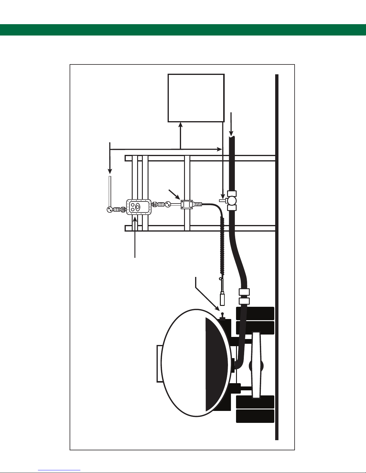
ST-47 Groundhog - Technical Manual
Diagram Appendix
6.6 DWG 61346 – Grounding Protection for Product Loading & Ofoading
-OR-
Pump
AC Power
Control Wiring Inputs
Cable
Plug &
Connector
Signal
Output
Model
SC-47CC
Control
System
Terminal
Automation
Product
From Pump
Hazardous Area
System Components
Emergency Shutdown
Mounted in Class I, Div 1, Group D
Groundhog™
Ground Verication
Model ST-47ELK
Monitor
Scully
Ground Ball
Flow
Control
Valve
Notes: 1. Overll Prevention Components Shown in Italics
are manufactured by the Scully Signal Co.
2. Flow control components shown are suggested
and may not apply in your facility.
Page 22.
Bottom Loaded Tank Truck or Trailer Loading Rack
Page 23
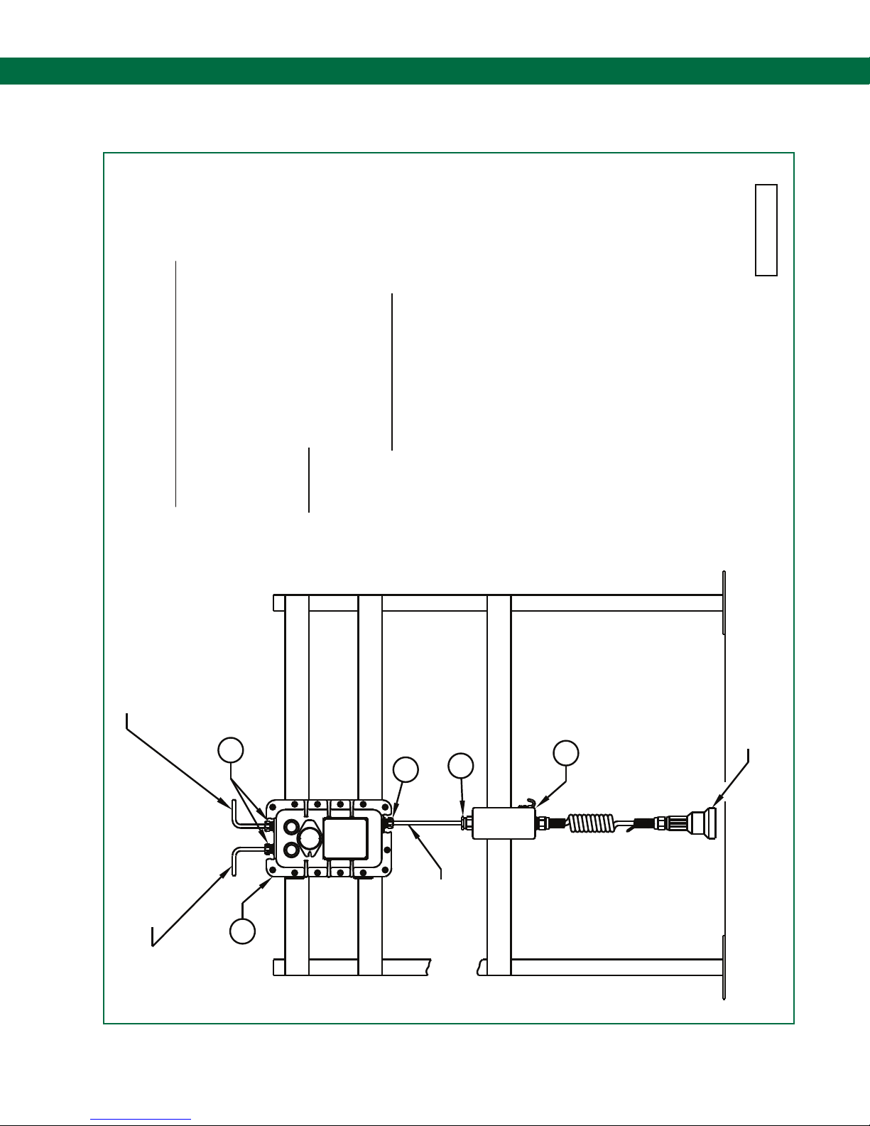
Self-Proving Vehicle Grounding Verication System
Diagram Appendix
6.7 DWG 61442 – Mounting Diagram – Control Unit & Junction Box
INSTALLATION NOTES
61442 RevC
EQUIPMENT SCHEDULE (TYPICAL)
1. CONTROL UNIT
(PLUG HOLE IF NOT USED)
ALTERNATIVE ENTRY FOR
OUTPUT CONTROL WIRING
MAINS POWER AND OUTPUT
CONTROL WIRING
IMPORTANT: INTRINSICALLY SAFE AND NON-INTRINSICALLY SAFE
MUST BE INSTALLED WITHIN 18 INCHES OF AN
EACH CONDUIT (NOT SHOWN).
EXPLOSION-PROOF ENCLOSURE IN A HAZARDOUS LOCATION, IN
IF CONDUITS ARE USED FOR CABLE ENTRY, SEAL FITTINGS
2. SCULCON JUNCTION BOX WITH PLUG AND CABLE.
3. FLAMEPROOF Exd CABLE GLAND FITTING.
4. INDUSTRIAL CABLE GLAND FITTING.
WIRING MUST ALWAYS BE SEPARATED AND
RUN IN SEPARATE CONDUITS/CABLES.
1. INSTALLATION MUST COMPLY WITH NATIONAL AND LOCAL
DETAILS SHOWN ARE FOR REFERENCE ONLY AND ARE NOT
REGULATIONS FOR INSTALLATIONS IN HAZARDOUS LOCATIONS
INTENDED TO REPRESENT CODE COMPLIANCE.
JUNCTION BOX MUST BE RUN USING DEDICATED CABLE
OR IN A CONDUIT. NO OTHER SIGNALS ARE TO BE RUN
OF THE CONTROL UNIT ENCLOSURE AND THE SCULCON
IN THIS CABLE OR CONDUIT.
2. THE INTRINSICALLY SAFE WIRING BETWEEN THE BOTTOM PORT
3. MINIMIZE LONG VERTICAL RUNS OF CABLE INTO THE TOP PORTS OF
3
3
4
AND THE CONTROL UNIT ENCLOSURE AT ALL CABLE PORT ENTRIES.
THE CONTROL UNIT ENCLOSURE TO AVOID CONDENSATION CHANNELING.
4. USE FIBER SEALING WASHERS BETWEEN THE CABLE GLAND FITTINGS
PLUGGED USING A CERTIFIED FLAMEPROOF STOPPER PLUG.
5. ANY UNUSED HOLES IN THE FLAMEPROOF ENCLOSURE MUST BE
2
OVERFILL PREVENTION SYSTEM ON
PLUG ASSEMBLY TO CONNECT TO
VEHICLE.
1
WIRING USING SEPARATE
INTRINSICALLY SAFE
CABLE
Page 23.
Page 24
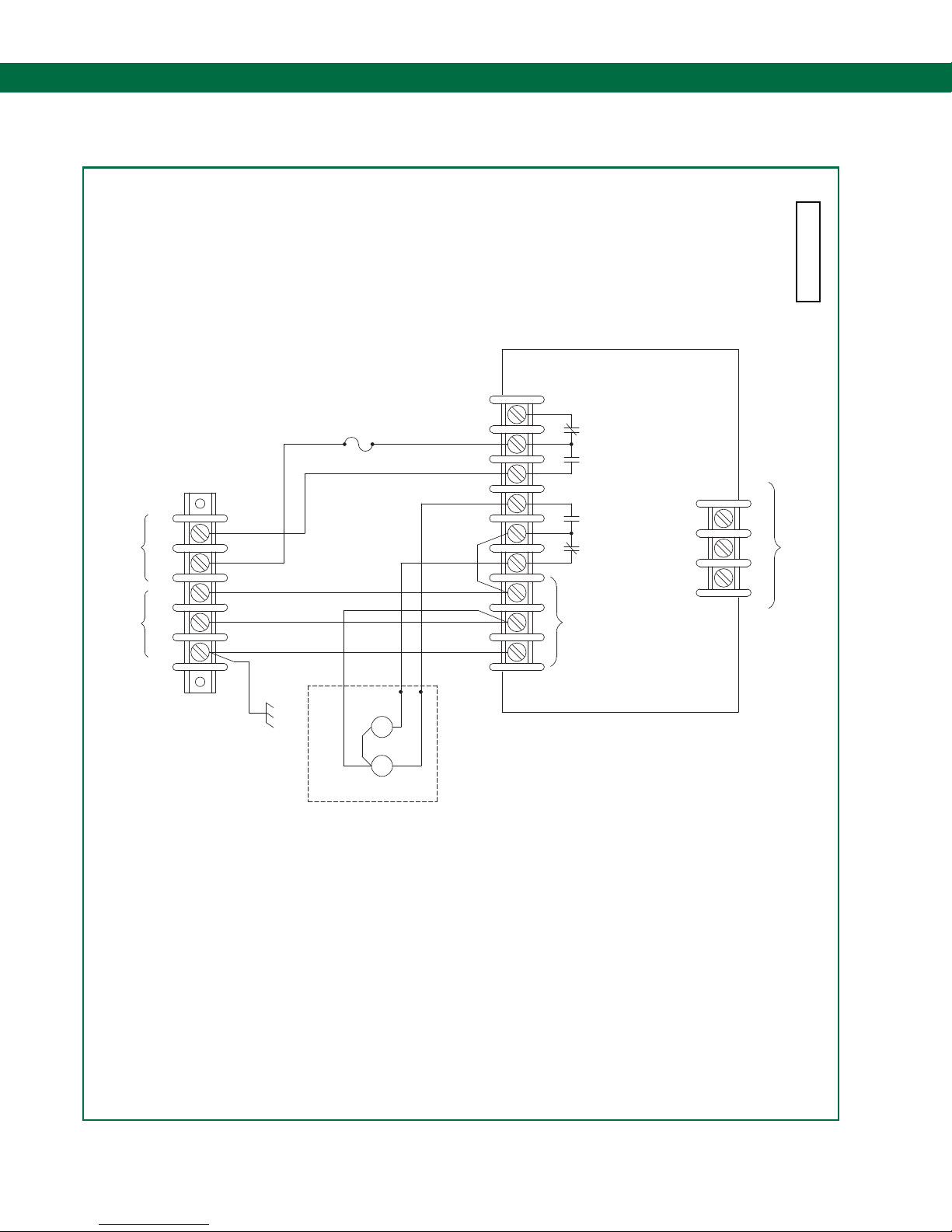
ST-47 Groundhog - Technical Manual
Diagram Appendix
6.8 DWG 61334 – Internal Wiring Diagram ST-47-EL
SEE NOTE 3
5
NO
4
CONTACT
INPUT
C
3
H
2
N
1
G
FREE PERMISSIVE
SPST VOLT
120 VAC
TB1
(END USER WIRING TERMINAL)
BRN
ORN
F15AFAST BLOW
ORN
ORN
YEL
BLK
RED
BLK
WHT
WHT
GRN
TB1
61334 RevA
TB2
WET DRY DRY WET
1 2 3
ST-47-120/240
CIRCUIT MODULE
CONNECTION TO GROUND
INPUT
120 VAC
1 2 3 4 5 6 7 8 9
BOLT OR GROUND BALL
5 AMP RESISTIVE.
IS IN PERMISSIVE MODE.
1. ``DRY'' CONTACTS CLOSE WHEN ST-47
NOTES: UNLESS OTHERWISE SPECIFIED-
3. USER REPLACEABLE FUSE.
2. PERMISSIVE CONTACT RATED 250 VAC
GRN
CHASSIS
GROUND
WHT
R
G
BLK
BLK
COMPONENTS
FRONT COVER
Page 24.
Page 25
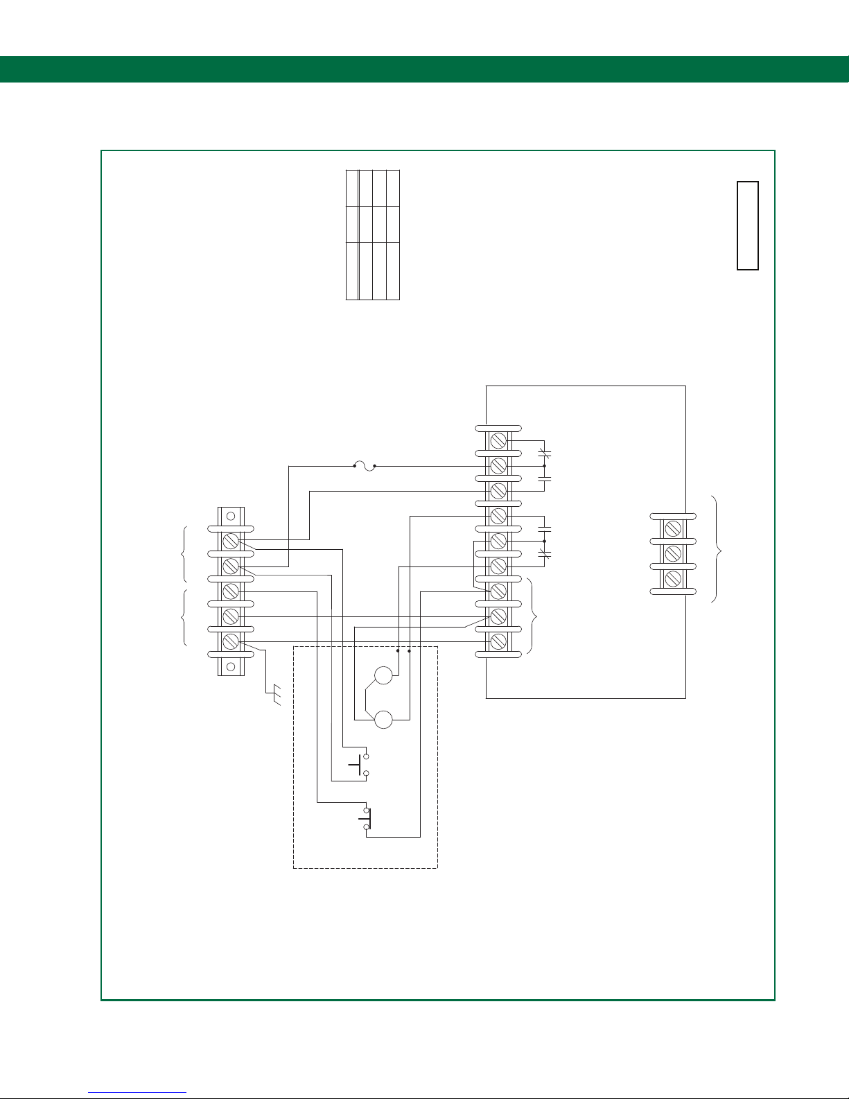
Self-Proving Vehicle Grounding Verication System
Diagram Appendix
6.9 DWG 61333 – Internal Wiring Diagram ST-47-ELK
00X
S1B
0X0
S1A
S1 OPERATION CHART
POS.
OFF
AUTO
BYPASS
X = SWITCH CLOSED
0 = SWITCH OPEN
TB1
61333 RevA
5
NO
4
CONTACT
INPUT
C
3
H
2
N
1
G
SPST VOLT
FREE PERMISSIVE
120 VAC
TB1
(END USER WIRING TERMINAL)
BRN
ORN
ORN
BLK
GRN
CHASSIS
GROUND
F15AFAST BLOW
SEE NOTE 4
BLK
BLK
R
WHT
G
S1B
S1A
ORN
BRN
YEL
RED
BLK
BLK
WHT
WHT
GRN
FRONT COVER COMPONENTS
WET DRY DRY WET
INPUT
120 VAC
1 2 3 4 5 6 7 8 9
TB2
ST-47-120/240
CIRCUIT MODULE
1 2 3
CONNECTION TO GROUND
BOLT OR GROUND BALL
1. ``DRY'' CONTACTS CLOSE WHEN ST-47 IS IN PERMISSIVE MODE.
3. SWITCH S1 SHOWN IN AUTO POSITION.
4. USER REPLACEABLE FUSE.
2. PERMISSIVE CONTACT RATED 250 VAC 5 AMP RESISTIVE.
NOTES: UNLESS OTHERWISE SPECIFIED-
Page 25.
Page 26
ST-47 Groundhog - Technical Manual
Diagram Appendix
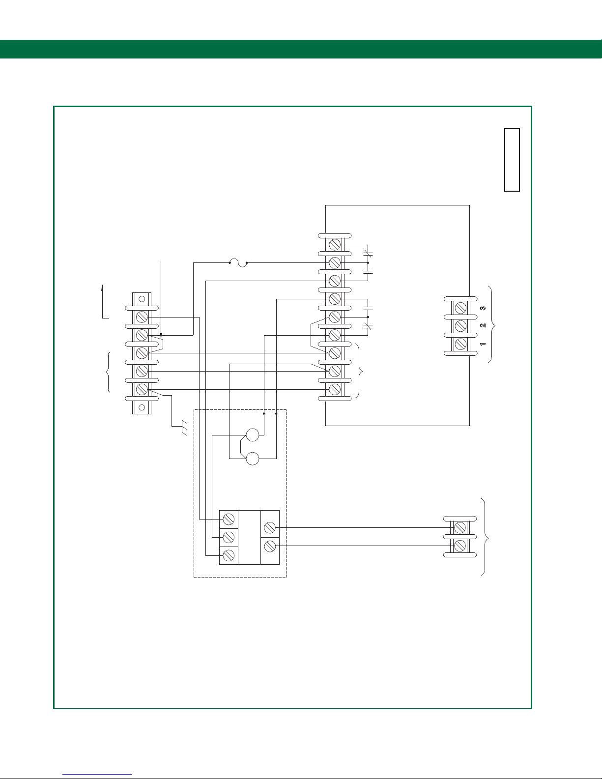
6.10 DWG 61331 – Internal Wiring Diagram ST-47-EL/D
TB1
F15AFAST BLOW
CONNECT TO LOAD
NOT TO EXCEED
135VAC, 5A
5
NO
4
C
3
H
2
N
INPUT
120 VAC
1
G
JUMPER
SEE NOTE 4
TB1
(END USER WIRING TERMINAL)
BRN
ORN
BLK
SEE NOTE 3
ORN
ORN
YEL
BLK
RED
BLK
WHT
WHT
GRN
61331 RevA
TB2
WET DRY DRY WET
ST-47-120/240
CIRCUIT MODULE
CONNECTION TO GROUND
INPUT
120 VAC
1 2 3 4 5 6 7 8 9
BOLT OR GROUND BALL
5 AMP RESISTIVE.
IS IN PERMISSIVE MODE.
1. ``DRY'' CONTACTS CLOSE WHEN ST-47
NOTES: UNLESS OTHERWISE SPECIFIED-
3. USER REPLACEABLE FUSE.
2. PERMISSIVE CONTACT RATED 250 VAC
GRN
CHASSIS
GROUND
POWER SOURCE FOR TB1-4. LOAD VOLTAGE
RANGE 100-135 VAC.
4. REMOVE JUMPER WHEN USING EXTERNAL
WHT
NEUT LOADHOT
N.O.
R
G
K1
BLK
BLK
COMPONENTS
FRONT COVER
WHT
BLK
TB3
DEADMAN SWITCH INPUT
Page 26.
Page 27
Self-Proving Vehicle Grounding Verication System
Diagram Appendix
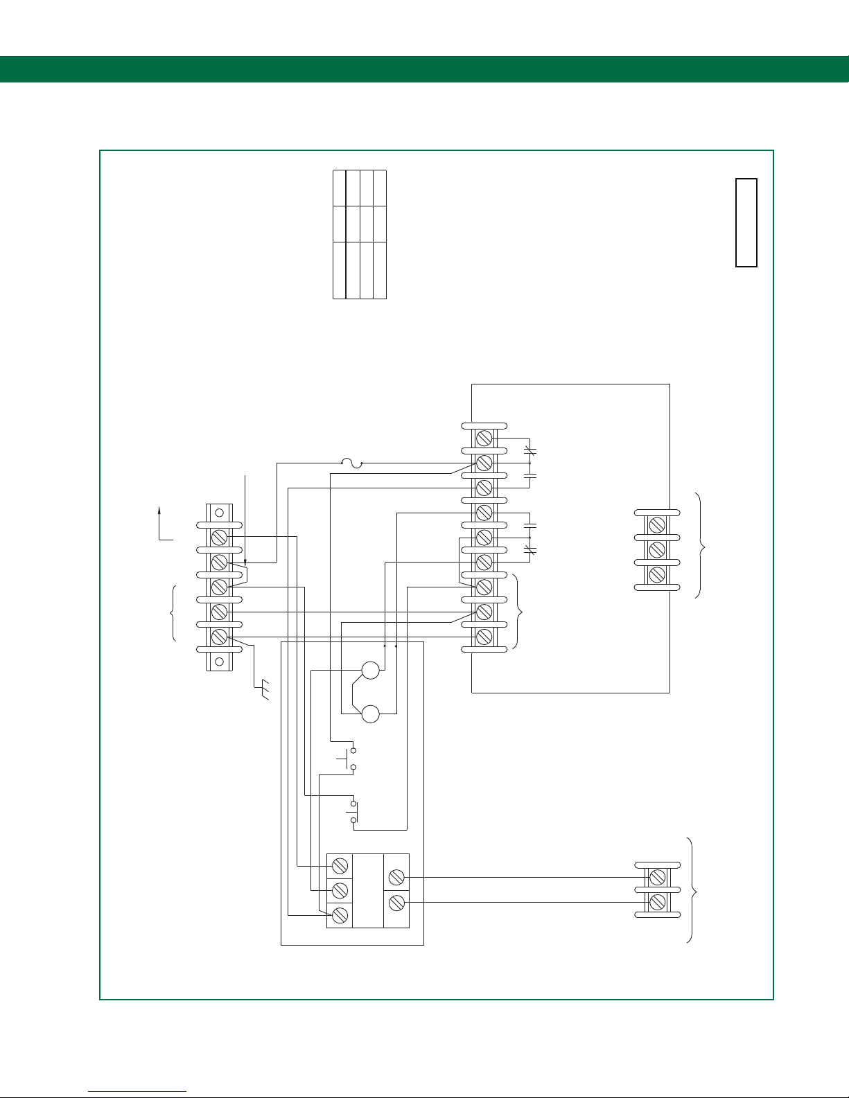
6.11 DWG 61332 – Internal Wiring Diagram ST-47-ELK/D
00X
S1B
0X0
S1A
S1 OPERATION CHART
POS.
OFF
AUTO
BYPASS
X = SWITCH CLOSED
0 = SWITCH OPEN
TB1
F15AFAST BLOW
135VAC, 5A
5
NO
4
C
3
H
2
N
1
G
TB1
CONNECT TO LOAD
NOT TO EXCEED
INPUT
120 VAC
JUMPER
SEE NOTE 5
(END USER WIRING TERMINAL)
VIO
ORN
BLK
BLK
GRN
SEE NOTE 4
BLK
BLK
R
RED
WHT
WHT
ORN
BLU
BRN
YEL
BLK
BLK
GRN
1 2 3 4 5 6 7 8 9
120 VAC
WET DRY DRY WET
INPUT
TB2
ST-47-120/240
CIRCUIT MODULE
61332 RevA
1 2 3
CONNECTION TO GROUND
BOLT OR GROUND BALL
CHASSIS
GROUND
FOR TB1-4. LOAD VOLTAGE RANGE 100-135 VAC.
1. ``DRY'' CONTACTS CLOSE WHEN ST-47 IS IN PERMISSIVE MODE.
NOTES: UNLESS OTHERWISE SPECIFIED-
5. REMOVE JUMPER WHEN USING EXTERNAL POWER SOURCE
3. SWITCH S1 SHOWN IN AUTO POSITION.
4. USER REPLACEABLE FUSE.
2. PERMISSIVE CONTACT RATED 250 VAC 5 AMP RESISTIVE.
WHT
BLU
WHT
S1A
S1B
NEUT LOADHOT
G
N.O.
K1
FRONT COVER COMPONENTS
WHT
BLK
TB3
DEADMAN SWITCH INPUT
Page 27.
Page 28
ST-47 Groundhog - Technical Manual
Diagram Appendix
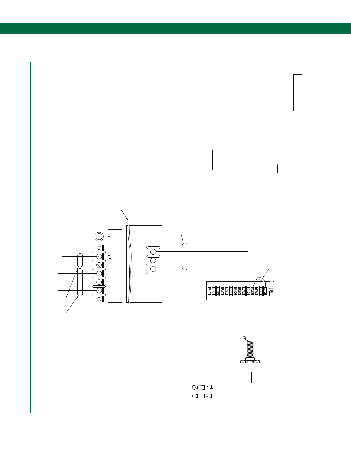
6.12 DWG 61121 – Field Wiring Diagram ST-47-115/240 EL(K)
61121 RevD
INPUT
120/240 VAC
CONTACTS THAT CLOSE ON PERMIT
250 VAC, 5A RESISTIVE
}
HOT
NEUT
GND
IMPORTANT: INTRINSICALLY SAFE AND NON-INTRINSICALLY
EXPLOSION-PROOF ENCLOSURE IN A HAZARDOUS LOCATION.
1. SEAL FITTINGS MUST BE INSTALLED WITHIN 18 INCHES OF AN
NOTES:
GROUP D HAZARDOUS LOCATION.
MOUNTED IN A CLASS I, DIVISION 1,
SAFE LOCATION OR SCULLY ST-47E
SCULLY ST-47 MOUNTED IN A
SAFE WIRING
CONDUIT-INTRINSICALLY
(SEE NOTES 1 & 2)
.
F1
.
FUSE
250V-5A
SIZE 3 AG
RATED 5 AMPS
CONTROL CONTACTS
HOT
NEUT
MAINS POWER
GND
``SLO-BLO''
3
2
250 VOLTS MAX
1
GROUNDHOG
TB-2
ST-47-120/240E(LK)
SAFE WIRING MUST ALWAYS BE SEPARATED AND
2
TB-1
IF POSSIBLE. IN ALL CASES WIRING MUST MEET APPLICABLE
COLOR OF WIRES SHOULD MATCH CONTROLLER TERMINAL COLORS-
NATIONAL, STATE AND LOCAL CODES.
FOR DETAILS.
4. INTERCONNECTION WIRING MUST NOT BE ALLOWED TO PASS
2. WIRE TO BE 18 AWG MINIMUM, STRANDED AND TINNED.
RUN IN SEPARATE CONDUITS.
3. OTHER SCULCON MODELS CAN BE USED. CONSULT FACTORY
ENTRY PORTS AND INTRINSIC SAFE (I.S.) WIRING MUST EXIT
(NON I.S.) WIRING MUST PASS IN AND OUT OF THE TOP CONDUIT
IS THE HOUSING TO BE USED AS A JUNCTION BOX. CONTROL
THROUGH THE ST-47 HOUSING. UNDER NO CIRCUMSTANCES
ONLY FROM THE BOTTOM CONDUIT ENTRY.
A
SEE VIEW
4
879
6
513
11
10
12
TB1
(SEE NOTE 3)
SCULCON BOX
MODEL SC-47CC
WHT
BLK
CONDUIT
SAFE WIRING
(SEE NOTE 1)
NON-INTRINSICALLY
Page 28.
A
GROUNDHOG PLUG (USED
VIEW
WITH SCULLY GROUND BALL)
Page 29
Self-Proving Vehicle Grounding Verication System
Diagram Appendix
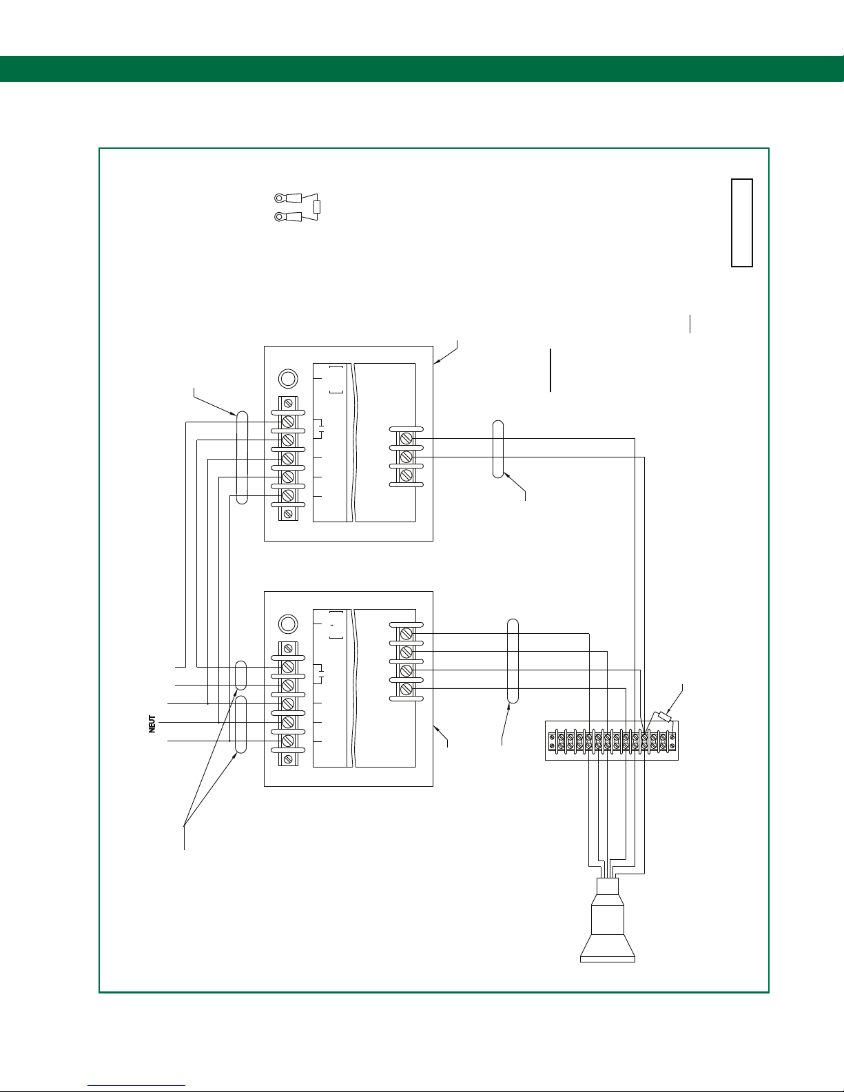
6.13 DWG 61099 – Field Wiring Diagram ST-35/ST-47
A
VIEW
GROUP D HAZARDOUS LOCATION.
ST-47E MOUNTED IN A CLASS I, DIVISION 1,
SCULLY ST-47 MOUNTED IN A SAFE LOCATION OR
.
CONDUIT
NON-INTRINSICALLY
SAFE WIRING
(SEE NOTE 1)
F1
.
FUSE
250V-5A
``SLO-BLO''
SIZE 3 AG
TB-2
GROUNDHOG
ST-47-120/240 E(LK)
3
2
1
RATED 5 AMPS
CONTROL CONTACTS
HOTGND NEUT
MAINS POWER
250 VOLTS MAX
TB-1
IMPORTANT: INTRINSICALLY SAFE AND NON-INTRINSICALLY
EXPLOSION-PROOF ENCLOSURE IN A HAZARDOUS LOCATION.
1. SEAL FITTINGS MUST BE INSTALLED WITHIN 18 INCHES OF AN
NOTES:
CONDUIT
RUN IN SEPARATE CONDUITS.
SAFE WIRING MUST ALWAYS BE SEPARATED AND
61099 RevF
NATIONAL, STATE AND LOCAL CODES.
IF POSSIBLE. IN ALL CASES WIRING MUST MEET APPLICABLE
COLOR OF WIRES SHOULD MATCH CONTROLLER TERMINAL COLORS-
2. WIRE TO BE 18 AWG MINIMUM, STRANDED AND TINNED.
FOR DETAILS.
CIRCUMSTANCES, ARE THE HOUSINGS TO BE USED AS JUNCTION
THROUGH THE ST-35 OR ST-47 HOUSINGS. UNDER NO
4. INTERCONNECTION WIRING MUST NOT BE ALLOWED TO PASS
3. OTHER SCULCON MODELS CAN BE USED. CONSULT FACTORY
WHT
ORN/BLK
WIRING MUST EXIT ONLY FROM THE BOTTOM CONDUIT ENTRY.
THE TOP CONDUIT ENTRY PORTS AND INTRINSIC SAFE (I.S.)
BOXES. CONTROL (NON I.S.) WIRING MUST PASS IN AND OUT OF
120/240 VAC
INPUT
250 VAC, 5A RESISTIVE
}
CONTACTS THAT CLOSE ON PERMIT
HOT
GND
CONDUIT
NON-INTRINSICALLY
SAFE WIRING
(SEE NOTE 1)
(SEE NOTES 1 & 2)
INTRINSICALLY SAFE WIRING
F1
FUSE
250V-5A
``SLO-BLO''
SIZE 3 AG
YEL
ORN
A
BLK
PLUG PIN 10 (WHT)
11
12
TANKER
CONNECTOR PLUG
SEE VIEW
TB1
SCULCON BOX
(SEE NOTE 3)
MODEL SC-6AO OR 6W
RATED 5 AMPS
CONTROL CONTACTS
HOTGND NEUT
MAINS POWER
250 VOLTS MAX
RED
4
1
2
TB-2
3
9
8
6
7
5
10
ST-35-120/240 E(LK)
TB-1
(SEE NOTES 1 & 2)
CONDUIT-INTRINSICALLY SAFE WIRING
DIVISION 1, GROUP D HAZARDOUS LOCATION.
OR SCULLY ST-35E MOUNTED IN A CLASS I,
SCULLY ST-35 MOUNTED IN A SAFE LOCATION
PLUG PIN 4 (GRN)
PLUG PIN 8 (BLU)
PLUG PIN 9 (ORN/BLK)
PLUG PIN 5 (RED)
PLUG PIN 6 (ORN)
Page 29.
Page 30
ST-47 Groundhog - Technical Manual
Diagram Appendix
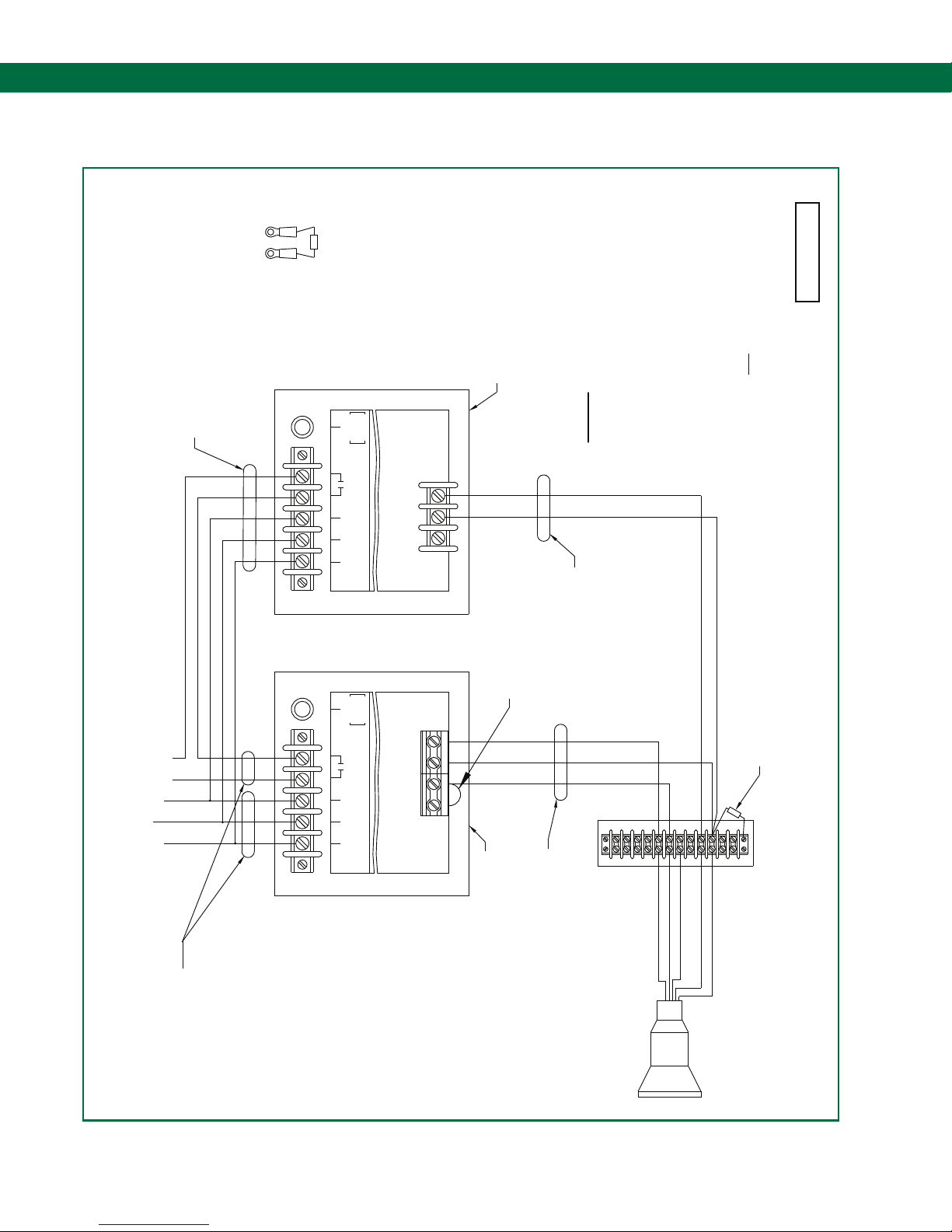
6.14 DWG 61098 – Field Wiring Diagram ST-15/ST-47
A
VIEW
GROUP D HAZARDOUS LOCATION.
ST-47E MOUNTED IN A CLASS I, DIVISION 1,
SCULLY ST-47 MOUNTED IN A SAFE LOCATION OR
.
CONDUIT
NON-INTRINSICALLY
SAFE WIRING
(SEE NOTE 1)
F1
.
FUSE
250V-5A
``SLO-BLO''
SIZE 3 AG
TB-2
RATED 5 AMPS
CONTROL CONTACTS
HOTGND NEUT
MAINS POWER
250 VOLTS MAX
3
2
GROUNDHOG
1
ST-47-120/240 E(LK)
TB-1
IMPORTANT: INTRINSICALLY SAFE AND NON-INTRINSICALLY
EXPLOSION-PROOF ENCLOSURE IN A HAZARDOUS LOCATION.
NOTES:
1. SEAL FITTINGS MUST BE INSTALLED WITHIN 18 INCHES OF AN
RUN IN SEPARATE CONDUITS.
SAFE WIRING MUST ALWAYS BE SEPARATED AND
CONDUIT
61098 RevD
NATIONAL, STATE AND LOCAL CODES.
IF POSSIBLE. IN ALL CASES WIRING MUST MEET APPLICABLE
COLOR OF WIRES SHOULD MATCH CONTROLLER TERMINAL COLORS-
2. WIRE TO BE 18 AWG MINIMUM, STRANDED AND TINNED.
FOR DETAILS.
BOXES. CONTROL (NON I.S.) WIRING MUST PASS IN AND OUT OF
CIRCUMSTANCES, ARE THE HOUSINGS TO BE USED AS JUNCTION
THROUGH THE ST-15 OR ST-47 HOUSINGS. UNDER NO
4. INTERCONNECTION WIRING MUST NOT BE ALLOWED TO PASS
3. OTHER SCULCON MODELS CAN BE USED. CONSULT FACTORY
WHT
ORN/BLK
IS TO BE CONNECTED TO MODEL SP-BLHK SENSORS.
WIRING MUST EXIT ONLY FROM THE BOTTOM CONDUIT ENTRY.
THE TOP CONDUIT ENTRY PORTS AND INTRINSIC SAFE (I.S.)
5. FACTORY INSTALLED JUMPER. DO NOT REMOVE UNLESS ST-15
120/240 VAC
INPUT
250 VAC, 5A RESISTIVE
}
CONTACTS THAT CLOSE ON PERMIT
HOT
NEUT
GND
CONDUIT
SAFE WIRING
(SEE NOTE 1)
NON-INTRINSICALLY
(SEE NOTES 1 & 2)
INTRINSICALLY SAFE WIRING
SEE NOTE 5
.
F1
.
FUSE
250V-5A
SIZE 3 AG
RATED 5 AMPS
CONTROL CONTACTS
HOTGND NEUT
MAINS POWER
``SLO-BLO''
250 VOLTS MAX
BLK
WHT
GRN
1
4
6
7
9
5
3
TB2
ST-15-120/240 E(LK)
2
8
10
TB-1
(SEE NOTES 1 & 2)
CONDUIT-INTRINSICALLY SAFE WIRING
DIVISION 1, GROUP D HAZARDOUS LOCATION.
OR SCULLY ST-15E MOUNTED IN A CLASS I,
SCULLY ST-15 MOUNTED IN A SAFE LOCATION
PLUG PIN 7 (BLK)
PLUG PIN 10 (WHT)
PLUG PIN 6 (ORN)
PLUG PIN 5 (RED)
PLUG PIN 9 (ORN/BLK)
A
SEE VIEW
11
12
TB1
(SEE NOTE 3)
SCULCON BOX
MODEL SC-3A
Page 30.
TANKER CONNECTOR PLUG
Page 31
Self-Proving Vehicle Grounding Verication System
Diagram Appendix
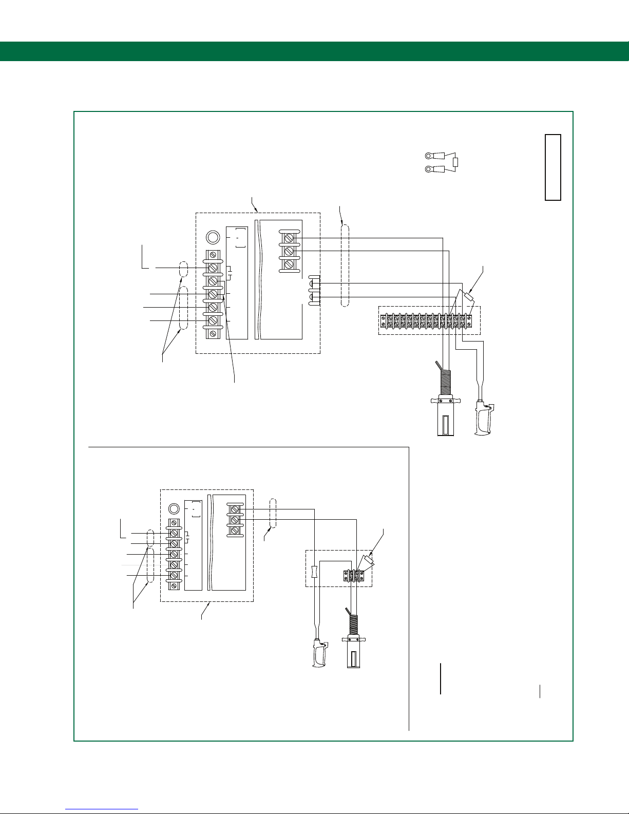
6.15 DWG 61141 – Field Wiring Diagram ST-47-115 EL(K)/D
HAZARDOUS LOCATION.
CLASS I, DIVISION 1, GROUP D
120 VAC
INPUT
WHEN PERMISSIVE
LINE OUTPUT TO LOAD
100-135 VAC, 5A MAX.
AND DEADMAN CLOSED
}
HOT
NEUT
GND
SCULLY ST-47E MOUNTED IN A
.
F1
.
FUSE
250V-5A
``SLO-BLO''
SIZE 3 AG
3
2
1
RATED 5 AMPS
CONTROL CONTACTS
HOTGND NEUT
MAINS POWER
250 VOLTS MAX
GROUNDHOG
WHT
TB-2
BLK
ST-47-120 E(LK)/D
TB-1
SAFE WIRING
CONDUIT-INTRINSICALLY
(SEE NOTES 1 & 2)
1
2
TB-3
A
VIEW
61141 RevD
SEE VIEW
WHT
ORN/BLK
8
746
5
3
BLK
9
10
11
12
TB1
(SEE NOTE 3)
SCULCON BOX
MODEL SC-47CC/D
WHT
BLK
WHT
INPUT
120/240 VAC
250V, 5A RESISTANCE
CLOSE ON PERMIT
DRY CONTACTS THAT
}
HOT
NEUT
GND
CONDUIT
MAX.
SAFE WIRING
(SEE NOTE 1)
NON-INTRINSICALLY
CONDUIT
NON-INTRINSICALLY
F1
TB-1
SAFE WIRING
(SEE NOTE 1)
.
.
FUSE
250V-5A
SIZE 3 AG
RATED 5 AMPS
CONTROL CONTACTS
MAINS POWER
GND NEUT HOT
``SLO-BLO''
250 VOLTS MAX
ST-47-120/240 E(LK)
SCULLY ST-47E MOUNTED IN A
CLASS I, DIVISION 1, GROUP D
HAZARDOUS LOCATION.
SEE NOTE 5
3
2
1
TB-2
GROUNDHOG
SAFE WIRING
CONDUIT-INTRINSICALLY
(SEE NOTES 1 & 2)
DEADMAN
SWITCH
GROUNDHOG PLUG (USED
WITH SCULLY GROUND BALL)
A
SEE VIEW
BLK
BLK
WHT
DEADMAN
SWITCH
WHT
9
10
TB1
SCULCON BOX
(SEE NOTE 3)
MODEL SC-47CC
WHT
BLK
ALTERNATE WIRING DIAGRAM
OLDER DEADMAN VERSIONS WITHOUT ``/D'' OPTION
WITH SCULLY GROUND BALL)
GROUNDHOG PLUG (USED
NATIONAL, STATE AND LOCAL CODES.
IF POSSIBLE. IN ALL CASES WIRING MUST MEET APPLICABLE
IMPORTANT: INTRINSICALLY SAFE AND NON-INTRINSICALLY
EXPLOSION-PROOF ENCLOSURE IN A HAZARDOUS LOCATION.
1. SEAL FITTINGS MUST BE INSTALLED WITHIN 18 INCHES OF AN
NOTES:
RUN IN SEPARATE CONDUITS.
SAFE WIRING MUST ALWAYS BE SEPARATED AND
COLOR OF WIRES SHOULD MATCH CONTROLLER TERMINAL COLORS-
2. WIRE TO BE 18 AWG MINIMUM, STRANDED AND TINNED.
FOR DETAILS.
IS THE HOUSING TO BE USED AS A JUNCTION BOX. CONTROL
THROUGH THE ST-47 HOUSING. UNDER NO CIRCUMSTANCES,
4. INTERCONNECTION WIRING MUST NOT BE ALLOWED TO PASS
3. OTHER SCULCON MODELS CAN BE USED. CONSULT FACTORY
SOURCE OF LINE VOLTAGE.
5. FACTORY INSTALLED JUMPER. REMOVE WHEN USING EXTERNAL
ONLY FROM THE BOTTOM CONDUIT ENTRY.
ENTRY PORTS AND INTRINSIC SAFE (I.S.) WIRING MUST EXIT
(NON I.S.) WIRING MUST PASS IN AND OUT OF THE TOP CONDUIT
Page 31.
Page 32
ST-47 Groundhog - Technical Manual
Diagram Appendix
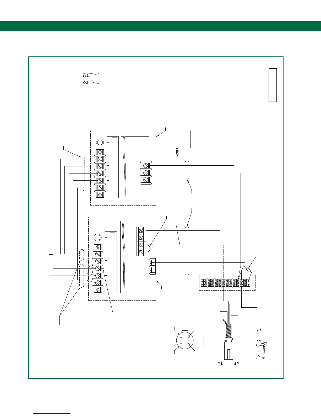
6.16 DWG 61168 – Field Wiring Diagram ST-15-ELK/D & ST-47
B
VIEW
GROUP D HAZARDOUS LOCATION.
ST-47E MOUNTED IN A CLASS I, DIVISION 1,
.
FUSE
.
.
FUSE
SIZE 3 AG
RATED 5 AMPS
CONTROL CONTACTS
HOTGND NEUT
MAINS POWER
.
250V-5A
SIZE 3 AG
250V-5A
``SLO-BLO''
TB-2
GROUNDHOG
ST-47-120 E(LK)
BLK
WHT
GRN
3
2
1
SEE NOTE 7
250 VOLTS MAX
``SLO-BLO''
EXPLOSION-PROOF ENCLOSURE IN A HAZARDOUS LOCATION.
1. SEAL FITTINGS MUST BE INSTALLED WITHIN 18 INCHES OF AN
NOTES:
SEE NOTE 6
IMPORTANT: INTRINSICALLY SAFE AND NON-INTRINSICALLY
SAFE WIRING MUST ALWAYS BE SEPARATED AND
CONDUIT
INTRINSICALLY SAFE WIRING
COLOR OF WIRES SHOULD MATCH CONTROLLER TERMINAL COLORS-
2. WIRE TO BE 18 AWG MINIMUM, STRANDED AND TINNED.
RUN IN SEPARATE CONDUITS.
(SEE NOTES 1 & 2)
CONDUIT
LINE OUTPUT TO LOAD WHEN PERMISSIVE
AND DEADMAN CLOSED 100-135 VAC, 5A MAX.
}
SAFE WIRING
(SEE NOTE 1)
NON-INTRINSICALLY
F1
TB-1
F1
IF POSSIBLE. IN ALL CASES WIRING MUST MEET APPLICABLE
NATIONAL, STATE AND LOCAL CODES.
FOR DETAILS.
CIRCUMSTANCES, ARE THE HOUSINGS TO BE USED AS JUNCTION
THROUGH THE ST-35 OR ST-47 HOUSINGS. UNDER NO
4. INTERCONNECTION WIRING MUST NOT BE ALLOWED TO PASS
3. OTHER SCULCON MODELS CAN BE USED. CONSULT FACTORY
SOURCE OF LINE VOLTAGE.
5. FACTORY INSTALLED JUMPER. REMOVE WHEN USING EXTERNAL
IS TO BE CONNECTED TO MODEL SP-BLHK SENSORS.
7. FACTORY INSTALLED JUMPER. DO NOT REMOVE UNLESS ST-15
6. THIS WIRE NOT REQUIRED FOR AVIATION OR MILITARY APPLICATIONS.
WIRING MUST EXIT ONLY FROM THE BOTTOM CONDUIT ENTRY.
THE TOP CONDUIT ENTRY PORTS AND INTRINSIC SAFE (I.S.)
BOXES. CONTROL (NON I.S.) WIRING MUST PASS IN AND OUT OF
WHT
ORN/BLK
B
SEE VIEW
61168 RevC
HOT
NEUT
120 VAC
GND
INPUT
TB-1
CONDUIT
SAFE WIRING
(SEE NOTE 1)
NON-INTRINSICALLY
Page 32.
RATED 5 AMPS
CONTROL CONTACTS
HOTGND NEUT
MAINS POWER
250 VOLTS MAX
SEE NOTE 5
ST-15-120 E(LK)/D
WHT
TB-2
BLK
4
7
8
9
6
513
TB-3
BLK
DIVISION 1, GROUP D HAZARDOUS LOCATION.
SCULLY ST-15EL(K)/D MOUNTED IN A CLASS I,
RED
WHT GRN
2
VIEW A-A
4-POLE PLUG FRONT VIEW
A
BLK
GRN
RED
WHT
10
11
12
TB1
(SEE NOTE 3)
SCULCON BOX
MODEL SC-1/D
WHT
SWITCH
DEADMAN
BLK
4-POLE PLUG
TANKER CONNECTOR
A
Page 33
Self-Proving Vehicle Grounding Verication System
Diagram Appendix
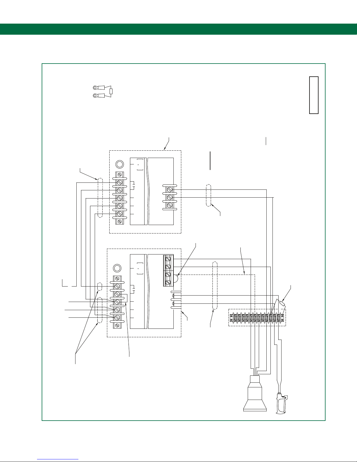
6.17 DWG 61167 – Field Wiring Diagram ST-15-ELK/D & ST-47
A
VIEW
GROUP D HAZARDOUS LOCATION.
OR ST-47E MOUNTED IN A CLASS I, DIVISION 1,
SCULLY ST-47 MOUNTED IN A SAFE LOCATION
.
CONDUIT
NON-INTRINSICALLY
SAFE WIRING
(SEE NOTE 1)
F1
.
FUSE
250V-5A
``SLO-BLO''
SIZE 3 AG
RATED 5 AMPS
CONTROL CONTACTS
NEUT
MAINS POWER
GND HOT
TB-2
250 VOLTS MAX
3
2
GROUNDHOG
1
ST-47-120 E(LK)
IMPORTANT: INTRINSICALLY SAFE AND NON-INTRINSICALLY
EXPLOSION-PROOF ENCLOSURE IN A HAZARDOUS LOCATION.
1. SEAL FITTINGS MUST BE INSTALLED WITHIN 18 INCHES OF AN
NOTES:
TB-1
SAFE WIRING MUST ALWAYS BE SEPARATED AND
RUN IN SEPARATE CONDUITS.
CONDUIT
IF POSSIBLE. IN ALL CASES WIRING MUST MEET APPLICABLE
COLOR OF WIRES SHOULD MATCH CONTROLLER TERMINAL COLORS-
NATIONAL, STATE AND LOCAL CODES.
3. OTHER SCULCON MODELS CAN BE USED. CONSULT FACTORY
2. WIRE TO BE 18 AWG MINIMUM, STRANDED AND TINNED.
FOR DETAILS.
WIRING MUST EXIT ONLY FROM THE BOTTOM CONDUIT ENTRY.
THE TOP CONDUIT ENTRY PORTS AND INTRINSIC SAFE (I.S.)
BOXES. CONTROL (NON I.S.) WIRING MUST PASS IN AND OUT OF
CIRCUMSTANCES, ARE THE HOUSINGS TO BE USED AS JUNCTION
THROUGH THE ST-15 OR ST-47 HOUSINGS. UNDER NO
4. INTERCONNECTION WIRING MUST NOT BE ALLOWED TO PASS
ORN/BLK
SOURCE OF LINE VOLTAGE.
5. FACTORY INSTALLED JUMPER. REMOVE WHEN USING EXTERNAL
WHT
IS TO BE CONNECTED TO MODEL SP-BLHK SENSORS.
7. FACTORY INSTALLED JUMPER. DO NOT REMOVE UNLESS ST-15
6. THIS WIRE NOT REQUIRED FOR AVIATION OR MILITARY APPLICATIONS.
61167 RevC
DEADMAN CLOSED. 100-135 VAC, 5A MAX.
LINE OUTPUT TO LOAD WHEN PERMISSIVE AND
}
HOT
NEUT
GND
120 VAC
INPUT
CONDUIT
NON-INTRINSICALLY
SAFE WIRING
(SEE NOTE 1)
(SEE NOTES 1 & 2)
CONDUIT-INTRINSICALLY SAFE WIRING
(SEE NOTES 1 & 2)
INTRINSICALLY SAFE WIRING
TANKER
CONNECTOR PLUG
SEE NOTE 6
A
SEE VIEW
4
789
6
513
2
12
11
10
TB1
(SEE NOTE 3)
SCULCON BOX
MODEL SC-3A/D
PLUG PIN 7 (RED)
PLUG PIN 6 (GRN)
PLUG PIN 10 (WHT)
PLUG PIN 9 (ORN/BLK)
BLK
WHT
DEADMAN
SWITCH
PLUG PIN 5 (BLK)
SEE NOTE 7
BLK
ST-15-120 E(LK)/D
TB-2
WHT
GRN
WHT
BLK
TB-3
.
.
FUSE
250V-5A
SIZE 3 AG
RATED 5 AMPS
CONTROL CONTACTS
HOTNEUT
MAINS POWER
GND
``SLO-BLO''
250 VOLTS MAX
F1
TB-1
SEE NOTE 5
DIVISION 1, GROUP D HAZARDOUS LOCATION.
OR SCULLY ST-15E MOUNTED IN A CLASS I,
SCULLY ST-15 MOUNTED IN A SAFE LOCATION
Page 33.
Page 34
ST-47 Groundhog - Technical Manual
Diagram Appendix
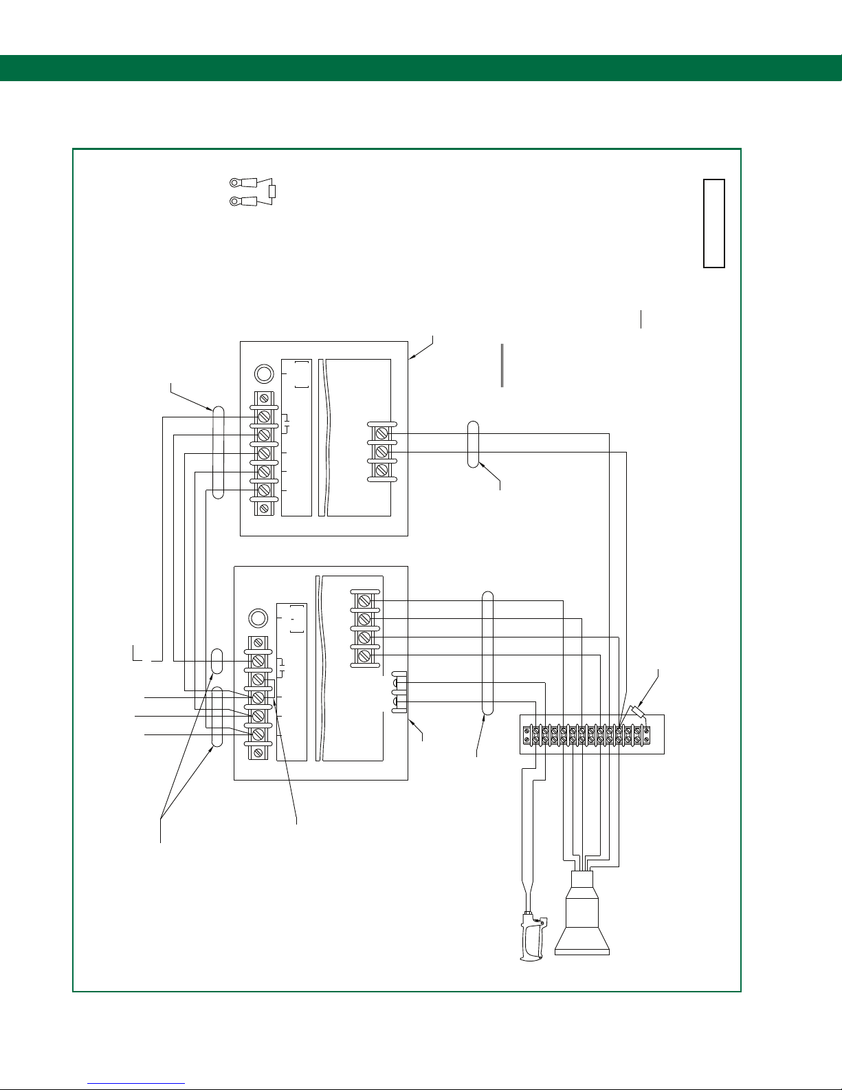
6.18 DWG 61169 – Field Wiring Diagram ST-35-ELK/D & ST-47
A
VIEW
ST-47E MOUNTED IN A CLASS I, DIVISION 1,
SCULLY ST-47 MOUNTED IN A SAFE LOCATION OR
GROUP D HAZARDOUS LOCATION.
.
CONDUIT
NON-INTRINSICALLY
SAFE WIRING
(SEE NOTE 1)
F1
TB-1
.
FUSE
250V-5A
SIZE 3 AG
RATED 5 AMPS
CONTROL CONTACTS
HOTNEUT
MAINS POWER
GND
``SLO-BLO''
TB-2
GROUNDHOG
ST-47-120 E(LK)
3
2
1
250 VOLTS MAX
IMPORTANT: INTRINSICALLY SAFE AND NON-INTRINSICALLY
EXPLOSION-PROOF ENCLOSURE IN A HAZARDOUS LOCATION.
1. SEAL FITTINGS MUST BE INSTALLED WITHIN 18 INCHES OF AN
NOTES:
SAFE WIRING MUST ALWAYS BE SEPARATED AND
RUN IN SEPARATE CONDUITS.
CONDUIT
(SEE NOTES 1 & 2)
INTRINSICALLY SAFE WIRING
2. WIRE TO BE 18 AWG MINIMUM, STRANDED AND TINNED.
61169 RevC
IF POSSIBLE. IN ALL CASES WIRING MUST MEET APPLICABLE
COLOR OF WIRES SHOULD MATCH CONTROLLER TERMINAL COLORS-
NATIONAL, STATE AND LOCAL CODES.
FOR DETAILS.
CIRCUMSTANCES, ARE THE HOUSINGS TO BE USED AS JUNCTION
THROUGH THE ST-35 OR ST-47 HOUSINGS. UNDER NO
4. INTERCONNECTION WIRING MUST NOT BE ALLOWED TO PASS
3. OTHER SCULCON MODELS CAN BE USED. CONSULT FACTORY
ORN/BLK
SOURCE OF LINE VOLTAGE.
5. FACTORY INSTALLED JUMPER. REMOVE WHEN USING EXTERNAL
WIRING MUST EXIT ONLY FROM THE BOTTOM CONDUIT ENTRY.
THE TOP CONDUIT ENTRY PORTS AND INTRINSIC SAFE (I.S.)
BOXES. CONTROL (NON I.S.) WIRING MUST PASS IN AND OUT OF
WHT
LINE OUTPUT TO LOAD WHEN PERMISSIVE
NEUT
120 VAC
INPUT
AND DEADMAN CLOSED 100-135 VAC, 5A MAX.
HOT
GND
YEL
ST-35-120 E(LK)/D
ORN
BLK
RED
A
WHT
TB-2
BLK
1
4
3
7
9108
6
5
2
TB-3
PLUG PIN 5 (RED)
PLUG PIN 6 (ORN)
(SEE NOTES 1 & 2)
DIVISION 1, GROUP D HAZARDOUS LOCATION.
SCULLY ST-35E MOUNTED IN A CLASS I,
CONDUIT-INTRINSICALLY SAFE WIRING
DEADMAN
PLUG PIN 4 (GRN)
BLK
WHT
SWITCH
PLUG PIN 10 (WHT)
PLUG PIN 8 (BLU)
PLUG PIN 9 (ORN/BLK)
SEE VIEW
11
12
TB1
(SEE NOTE 3)
SCULCON BOX
MODEL SC-6W/D
TANKER CONNECTOR PLUG
F1
FUSE
250V-5A
``SLO-BLO''
SIZE 3 AG
}
RATED 5 AMPS
250 VOLTS MAX
CONTROL CONTACTS
HOT
NEUT
MAINS POWER
GND
TB-1
SEE NOTE 5
CONDUIT
SAFE WIRING
(SEE NOTE 1)
NON-INTRINSICALLY
Page 34.
Page 35
Self-Proving Vehicle Grounding Verication System
1
2
8
5 4 3 9
12
13
15
14
7
6
Dynamic Self-Testing® Overll Prevention Systems
Diagram Appendix
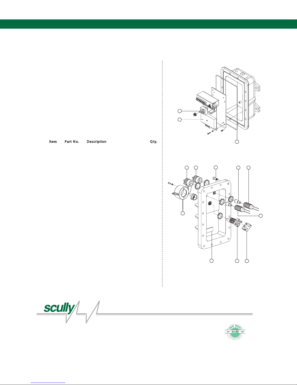
6.19 DWG 61202 – Replacement Parts for ST-47-115
REPLACEMENT PARTS for ST-47 115VAC
Groundhog™ Controller
FM Models
Part No. Model
08508 ST-47-115 EL
08220 ST-47-115 ELK
Note: Controller Models Sux:
Explosion-proof housing (E), Indicator Lights (L), Key (K) Lockable
Bypass Switch.
Replacement Parts
1 26311 Control Fuse, 5 Ampere 1
2 09511 ST-47C-115 Replacement Module 1
4 09124 Replacement Lens and
5 09125 Replacement Lens and
6 08350 Bypass Switch Lock Box
10 09384 LED Bulb, Red 1
11 09385 LED Bulb, Green 1
12 08343 Pilot Light Replacement LED Kit, Red 1
13 08342 Pilot Light Replacement LED Kit, Green 1
14 26022 Bypass Switch Contact Block 1
15 26055 Bypass Switch Operator 1
Notes:
Item 3: Hex-head screw used on models built after 10/92.
Item 8: O-ring used on models built after 10/92.
*Replacement Bulb for incandescent style explosion-proof lights only.
.ytQnoitpircseD.oN traP metI
61daeH xeH,wercS140053
Guard Assembly, Red 1
Guard Assembly, Green 1
(includes 2 mounting screws).1
1eluspaC noisorroC337127
1laes revoc gnir-O043138
2W6 ,V531 ,bluB500729*
(includes 4,10,12)
(includes 5, 11,13)
3-Position
MaxSafety
®
SYSTEMS
Scully Signal Company
70 Industrial Way,
Wilmington, MA 01887-3479, USA
Tel: 800 272 8559
email: [email protected]
/ 617 692 8600
Scully Systems Europe NV
Eksterveldlaan 31a
2820 Bonheiden
Tel: +32 (0) 15 56 00 70
email: [email protected]
/ Belgium
Scully UK Ltd
Meridian House, Unit 33,
37 Road One Winsford Industrial Estate,
Winsford Cheshire CW7 3QG
Tel.: +44 (0) 1606 553805
email: [email protected]
/ UK
61202, Rev E 2013
Page 35.
Page 36
ST-47 Groundhog - Technical Manual
2
8
5
4 3
9
10
11
13
127
6
1
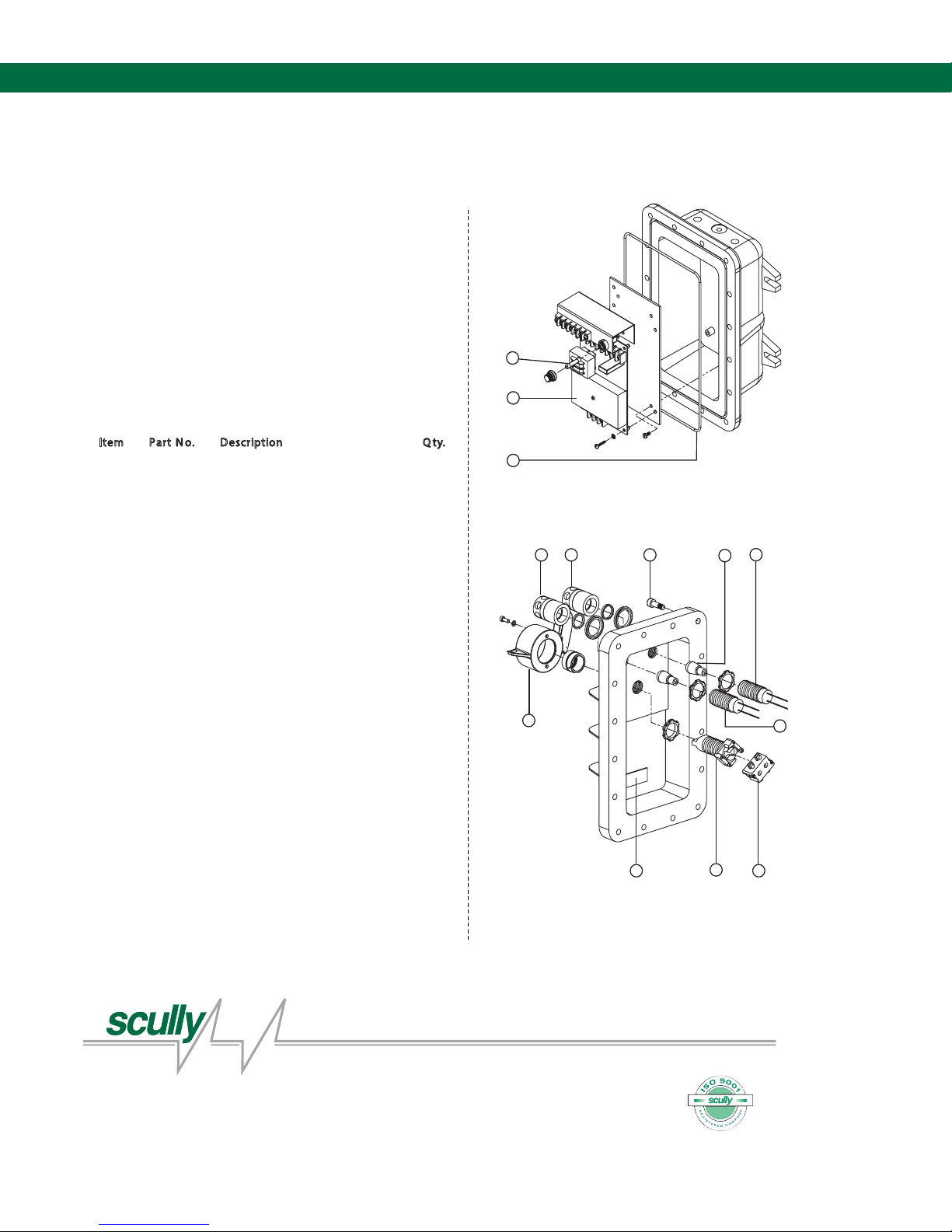
REPLACEMENT PARTS for ST-47 240VAC
Groundhog™ Controller
FM Models
Part No. Model
08675 ST-47-240 EL
08502 ST-47-240 ELK
Note: Controller Models Sux:
Explosion-proof housing (E), Indicator Lights (L), Key (K) Lockable
Bypass Switch.
Replacement Parts
1 26311 Control Fuse, 5 Amperes 1
2 09512 ST-47-240 Replacement Module 1
61daeH xeH ,wercS140053
4 09122 Replacement Lens and 1
Guard Assembly, Red
5 09123 Replacement Lens and 1
Guard Assembly, Green
6 08350 Bypass Switch Lock Box 1
(includes 2 mounting screws)
1eluspaC noisorroC337127
1laes revoc gnir-O043138
2W01 ,V042 ,bluB600729
10 08346 Pilot Light Replacement Kit, Red 1
(includes 4, 9 & 10)
11 08345 Pilot Light Replacement Kit, Green 1
(includes 5, 9 & 11)
12 26022 Bypass Switch Contact Block 1
13 26055 Bypass Switch Operator, 1
3-Position
Notes:
Item 3: Hex-head screw used on models built after 10/92.
Item 8: O-ring used on models built after 10/92.
61273, Rev C 2013
.ytQnoitpircseD.oN traP metI
Dynamic Self-Testing® Overll Prevention Systems
MaxSafety
®
SYSTEMS
Scully Signal Company
70 Industrial Way,
Wilmington, MA 01887-3479, USA
Tel: 800 272 8559
/
617 692 8600
email: [email protected]
Scully Systems Europe NV
Eksterveldlaan 31a
2820 Bonheiden
/
Belgium
Tel: +32 (0) 15 56 00 70
email: [email protected]
Scully UK Ltd
Meridian House, Unit 33,
37 Road One Winsford Industrial Estate,
Winsford Cheshire CW7 3QG
/
UK
Tel.: +44 (0) 1606 553805
email: [email protected]
Diagram Appendix
6.20 DWG 61273 – Replacement Parts for ST-47-240
Page 36.
Page 37

Notes:
Page 37.
Page 38

Notes:
Page 38.
Page 39

Page 40
Scully - Setting Standards in Safety and Dependability since 1936.
For over seventy-ve years Scully has been engineering and building products to
the highest safety and reliability standards. We design and manufacture all of our
systems under one roof to ensure complete quality control over our manufacturing
and testing operations. Scully is ISO certied and all of our products are 100%
made in the U.S.A. In addition, we back up our products with the best service in
the industry. We have direct sales and service personnel in the U.S.A., The United
Kingdom, and Europe and are represented in over 50 countries.
For more information and 24 hour technical assistance,
call Scully Signal Company at 1-800-SCULLY (1-800-272-8559).
Scully Headquarters in Wilmington, MA U.S.A.
Copyright © 2013 Scully Signal Company. MaxSafety, Sculcon and Scully are registered
trademarks of Scully Signal Company. The names and logos of other companies mentioned
herein may be trademarkes of their respective owners. This document is for informational
purposes only. Scully makes no warranties, expressed or implied, in this document. All Rights
Reserved. Specications are subject to change without notice.
MaxSafety
®
SYSTEMS
Dynamic Self-Testing® Overll Prevention Systems
Scully Signal Company
70 Industrial Way,
Wilmington, MA 01887-3479, USA
Tel: 800 272 8559
email: [email protected]
/ 617 692 8600
Scully Systems Europe NV
Eksterveldlaan 31a
2820 Bonheiden
Tel: +32 (0) 15 56 00 70
email: [email protected]
/ Belgium
61053 Rev H
January 2013
Scully UK Ltd
Meridian House, Unit 33,
37 Road One Winsford Industrial Estate,
Winsford Cheshire CW7 3QG
Tel.: +44 (0) 1606 553805
email: [email protected]
/ UK
 Loading...