

Scully ST-35C-120 EL, ST-35C SEries, ST-35C-240 ELK, ST-35C-120 ELK, ST-35C-240 EL Technical Manual
Page 1
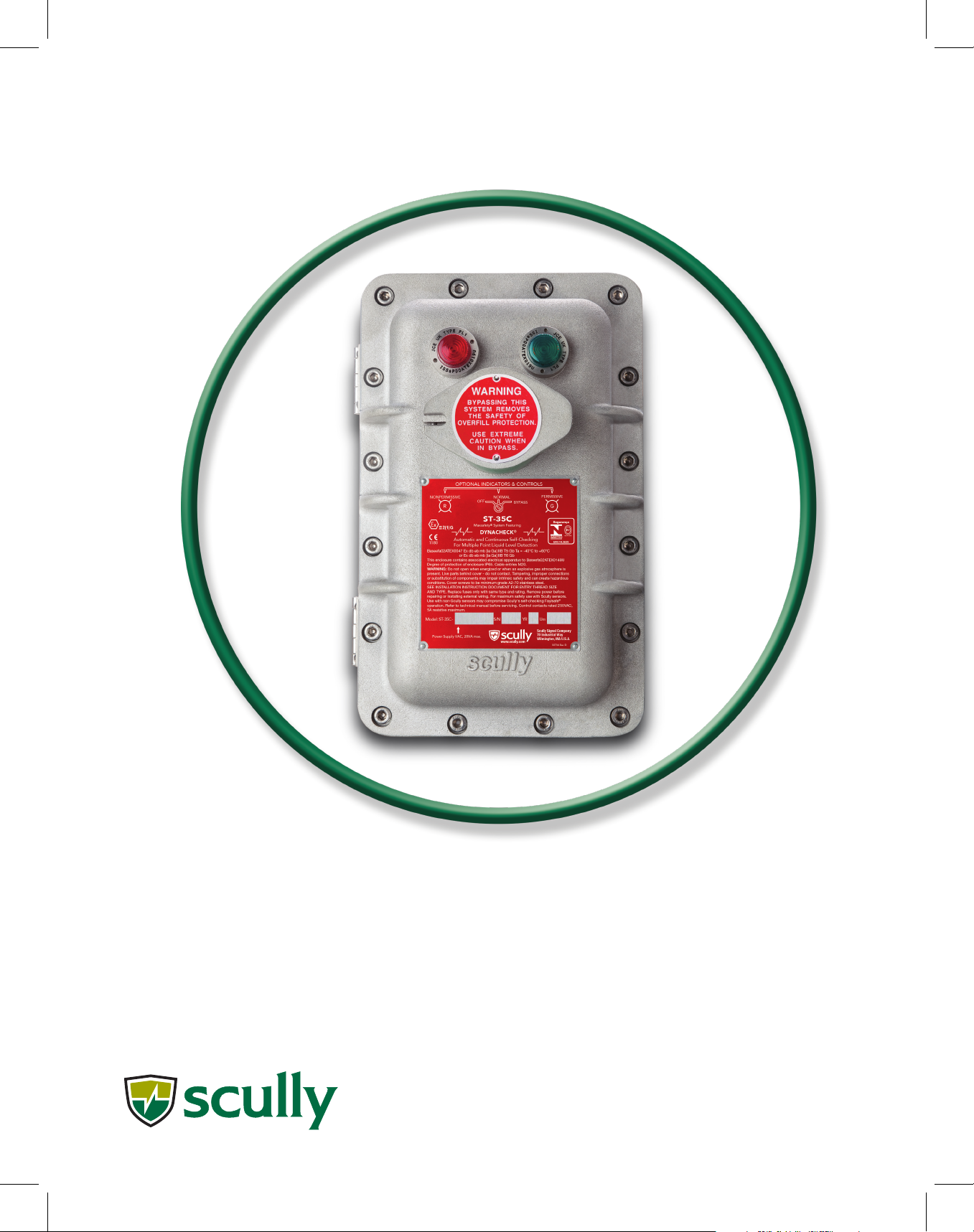
Scully ST-35C
Technical Manual
Multiple Point Overll Prevention
Control Monitor
Scully Signal Company 70 Industrial Way, Wilmington, MA 01887, USA • 800-272-8559 • [email protected] • www.scully.com
Page 2

Page 3

ST-35C - Technical Manual
1.3 Accessory Equipment
2.2 Electrical Installation
3.2 Corrosion Protection
Table of Contents
General
1.2 Technical Specications 6.
1.1 Description 4.
7.
Installation
2.1 Mechanical Installation 8.
8.
2.3 Initial System Checkout 10.
2.4 System Operation 11.
Maintenance
3.1 Enclosure 12.
12.
3.3 Control Module (Circuit Board) 12.
3.4 Module Replacement 12.
3.5 Indicator Lights 14.
3.6 Control (Bypass) Switch 14.
3.7 Junction Box and Plug & Cable Unit 14.
3.8 Fuses Replacement Description 14.
3.9 Troubleshooting 15.
Diagram Appendix
4.2 DWG 63039 – Outline Drawing – Sculcon Junction Box
4.3 DWG 61441 – Wiring Diagram - Typical Loading Rack Control 18.
4.4 DWG 61442 – Mounting Diagram – Control Unit & Junction Box
4.6 DWG 31307 – Internal Wiring Diagram – ST-35C-ELK 21.
4.7 DWG 61145 – Installation Wiring Diagram 22.
4.8 DWG 61406 – Installation Wiring Diagram, ST-35C/ST-47C 23.
4.1 DWG 31412 – Outline Drawing – Control Unit Enclosure 16.
4.5 DWG 31306 – Internal Wiring Diagram – ST-35C-EL 20.
17.
19.
4.10 DWG 61224 – Replacement Parts ST-35C-240 VAC 25.
4.9 DWG 61559 – Replacement Parts ST-35C-120 VAC 24.
Page 4

ST-35C - Technical Manual
General
The ST-35C Control Unit is used for overll prevention at loading terminals. In most tank truck
loading applications, volume to be loaded into each compartment is pre-set via a pre-set meter.
Under normal conditions the pre-set meter shuts down the loading after the pre-set volume is
loaded. The liquid does not reach the overll sensor as it is set at a level higher than the rated
capacity of each compartment. However, if the liquid level goes above the rated capacity of a
compartment, Scully’s ST-35C Overll Prevention system detects this overll condition and shuts
down the loading. Thus, it acts as a secondary (emergency) shutdown system, primary shutdown
control being provided by the pre-set meter.
The ST-35C Overll prevention Control Unit interfaces with 5-wire optic sensors. It is typically used
for overll prevention on bottom loading or top loading vehicles. It can monitor multiple sensors
(i.e. multi-compartment vehicles). It is mounted at the loading rack/gantry and connects to the
vehicle via a Scully plug and cable assembly.
The system incorporates Scully’s unique and exclusive Dynacheck® concept. To ensure that it will
always detect an overll condition, the controller uses pulsed signals which continuously check the
entire system operation including the controller, wiring connections and sensors. If a sensor comes
in contact with liquid, or in the unlikely event of a system fault, the pulsed signals cease, and the
controller automatically signals for immediate shutdown of the loading operation.
The ST-35C uses intrinsically safe voltage and current to connect to Scully liquid level sensors and
provides control for external electrical devices by opening and closing relay contacts.
Scully loading rack overll protection monitors have been carefully engineered to provide reliable
and safe performance when installed in conjunction with related Scully equipment according to the
instructions in this manual. Adaptations of, and additions to this equipment such as the use of
multiple cables and plugs, loading arm position indicating switches, enclosure heaters and similar
peripheral devices may void warranties unless authorized in writing by Scully Signal Company.
Please contact Scully prior to performing any installation or maintenance not specically described
in this manual.
1.1 Description
The ST-35C is for use with Scully 5-Wire Optic Sensors, Model SP-FU series. It can monitor up to
twelve (12) of these sensors in a “series” signal path. If any one of the connected sensors senses
liquid, the ST-35C will respond to this “wet” condition; output relay contact opens, and red light
turns on. Although its typical application is monitoring of sensors mounted on multi-compartment
vehicles, it is also used for high level detection in storage tanks (tank farms). One relay output
contact is provided, which opens if any sensor detects liquid.
ST-35C is also used with vehicles equipped with Scully’s IntelliCheck® series or ONBOARD Overll
Prevention Monitors. It interfaces with 5-wire optic socket on these vehicles. The ST-35C Control
Unit has an explosion proof enclosure for mounting in locations that are classied as hazardous.
Page 4.
Page 5
Multiple Point Overll Prevention Control Monitor
General
1.1.1 Model Designations
The ST-35C Controller is available in 120VAC or 240VAC models, with or without control (bypass)
switch.
Model sufx (E) = Explosion-proof Enclosure, (L) = Indicator Lights, (K) = Key Lockable Bypass
Switch.
Model Description
ST-35C-120 EL Multiple-Point Controller in Explosion-proof Enclosure with Indicator Lights,
120VAC
ST-35C-120 ELK Multiple-Point Controller in Explosion-proof Enclosure with Indicator Lights and
Key-lockable Bypass Switch, 120VAC
ST-35C-240 EL Multiple-Point Controller in Explosion-proof Enclosure with Indicator Lights,
240VAC
ST-35C-240 ELK Multiple-Point Controller in Explosion-proof Enclosure with Indicator Lights and
Key-lockable Bypass Switch, 240VAC
1.1.2 Explosion Proof Enclosure
Sufx “E” in the model number indicates controller is in an explosion-proof enclosure suitable for
hazardous areas. Conduit holes are provided in the enclosure for electrical access. The installer
must install Exd cable glands (or conduit and seal ttings) according to local codes.
1.1.3 Indicator Lights
Sufx “L” in the model number indicates red and green indicator lights on the controller enclosure.
These lights indicate the following conditions:
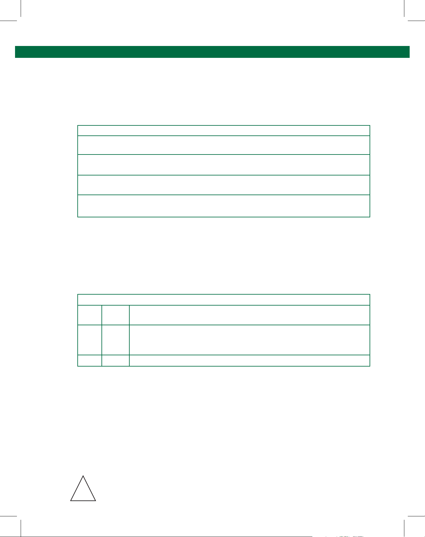
GREEN RED Condition
ON OFF All optic sensors are dry and the circuit is functioning properly.
Controller output is in permissive state i.e. permit to load.
OFF ON One or more sensors are wet or faulty or no connection to sensors, or
the circuit is malfunctioning. Controller output is in non-permissive state i.e. no
permit to load.
OFF OFF No power to the unit or Bypass Control Switch is in OFF or BYPASS position.
1.1.4 Bypass Control Switch
Adding the sufx “K” to the model number adds a lockable three-position control switch to the
enclosure.
• In the ‘OFF’ position, there is no power to the unit.
• In the ‘NORMAL’ position, the unit will operate normally, with “dry” sensors causing the
output relay to become energized (i.e. closed output contact).
• In the “BYPASS” position, power to the unit is switched “OFF” and the normally
open relay contacts are bypassed to permit emergency operation of the equipment,
without overll protection.
For normal operation, this switch should always be set in the NORMAL position. The switch is
enclosed in lockable box to allow locking with a user provided padlock.
CAUTION: When in ‘BYPASS’ mode the controller and sensors are DISABLED
and the system does not provide overll protection.
!
Page 5.
Page 6
ST-35C - Technical Manual
General
1.1.5 Indicator Light on Control Module
An internal red LED light is provided on the control module for convenience in checking the output
status when the cover is open. The light is ON when power is applied and dry and functional
sensors are connected to the unit. Thus, the internal light is ON when external green light is ON.
1.2 Technical Specications
Temperature Range -20°C to +60°C
Power Requirements 120VAC Models: 100 – 130 VAC, 50/60 Hz, 20VA Max.*
240VAC Models: 200 – 250 VAC, 50/60 Hz, 20VA Max.*
*20VA does not include circuits controlled by the output relay contact
Sensors: Up to 12 of Scully’s 5-wire optic sensors, Model SP-FU series.
Output Relay: One normally open volt-free contact rated 250VAC, 5A resistive max.
The output contact closes when all sensors are dry and functional.
Response Time: 0.5 second maximum
Indicator Lights: Output status indicator lights:
Red: Non-permissive
Green: Permissive
Output Control Fuse: Internal 5 Ampere
Connections: Provided by internal terminal strips.
Enclosure: Explosion-proof, weatherproof IP65.
Dimensions: See Appendix 4.1 for outline drawing.
Weight: 12.7 Kg (28 Lbs.)
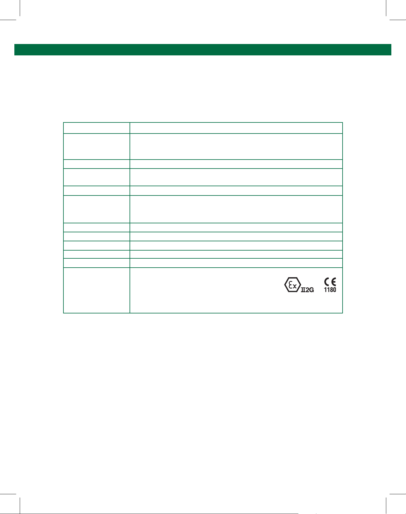
Approvals: Baseefa02ATEX0047 Ex db [iaGa] mb IIB T5 Gb Ta=-40°c to +60°c
or Ex db mb [ia Ga] IIB T6 Gb
The enclosure contains associated electrical apparatus to
Baseefa02ATEX0148U [Ex ia] IIB (Tamb-40°C to +70°C) Gb
Degree of protection of enclosure IP65. The rating of the enclosure is negated if the holes in the
enclosure are unplugged/unscrewed or any holes are drilled into the enclosure.
The ST-35C control unit has been designed to be impact-resistant. Do not subject to excessive
mechanical or thermal stresses. Do not allow the unit to come in contact with aggressive
substances that may degrade the integrity of the enclosure.
The ST-35C may only be repaired by replacing the internal control module. The internal control
module is non-repairable.
Do not open when an explosive gas atmosphere is present.
Page 6.
Page 7

Multiple Point Overll Prevention Control Monitor
General
1.3 Accessory Equipment
In addition to the control unit, a plug and cable assembly is needed to provide the inter-connection
from the ST-35C Control Unit to the vehicle. Plug and cable assemblies are available with various
plugs conforming to industry standard congurations and with coiled or straight cables in various
lengths.
Scully highly recommends the use of our Sculcon® Junction Box with Plug and Cable assembly.
Use of Sculcon junction box simplies system installation and provides for easy service of the plug
and cable assembly for maintenance. Wiring the plug and cable assembly directly into the bottom
of the ST-35C enclosure is not recommended and will result in greatly increased maintenance time
and difculty when the plug and cable assembly requires maintenance.
1.3.1 Sculcon Junction Box with Plug and Cable Assembly
One of the following models is needed to make connection to a vehicle. The selection is based on
the style of socket used on the vehicles. “W” style plugs connect to “W” style sockets (i.e. with 3
J-slots). “B” style plugs connect to “B” style sockets (i.e. 4 J-slots).
Model Description
SC-6W Sculcon Junction Box with 6W Blue Poly Plug & Cable. The 6W style plug has
3- bayonet pins (for attachment to truck socket) and 6 contact pins. The
SC-6W is available with either a 9 meter (30 feet) Coiled Cable or 6 meter
(20 feet) Straight Cable conguration.
This plug style is the standard in countries/regions that employ 3 J-slot
sockets on vehicles with 5-wire optic sensors
SC-6OB Sculcon Junction Box with 6OB Blue Poly Plug & Cable. The 6OB style plug
has 4- bayonet pins (for attachment to truck socket) and 6 contact pins.
The SC-6OB is available with either a 9 meter (30 feet) Coiled Cable or 6 meter
(20 feet) Straight Cable conguration.
This plug style is used in countries/regions that employ 4 J-slot sockets on
vehicles with 5-wire optic sensors.
Consult factory for additional models.
Page 7.
Page 8

ST-35C - Technical Manual
Installation
The ST-35C control system is typically installed in areas that are classied as hazardous locations
due to nature of the products being loaded. Installation of the control unit and accessories must
therefore be done by qualied personnel in accordance with all national and local regulations
(codes) governing the installation of electrical equipment in hazardous locations.
It is essential that the ST-35C control unit and accessories be installed and used in accordance with
the detailed specications and instructions in this manual. Installations that violate national and
local regulations (codes) for installation of electrical equipment in hazardous locations and/or
details in this manual may lead to unsafe operation.
Intrinsically safe wiring to/from TB2 at the bottom of the control module must enter/exit the
bottom opening in the control unit enclosure labeled “Intrinsically Safe Entry”. Intrinsically safe
wiring must be kept physically separated from any other wiring.
2.1 Mechanical Installation
When choosing a location on the loading rack for the control unit, the lights on the front of the
control unit should be readily visible and within easy reach of the user. The control unit should be
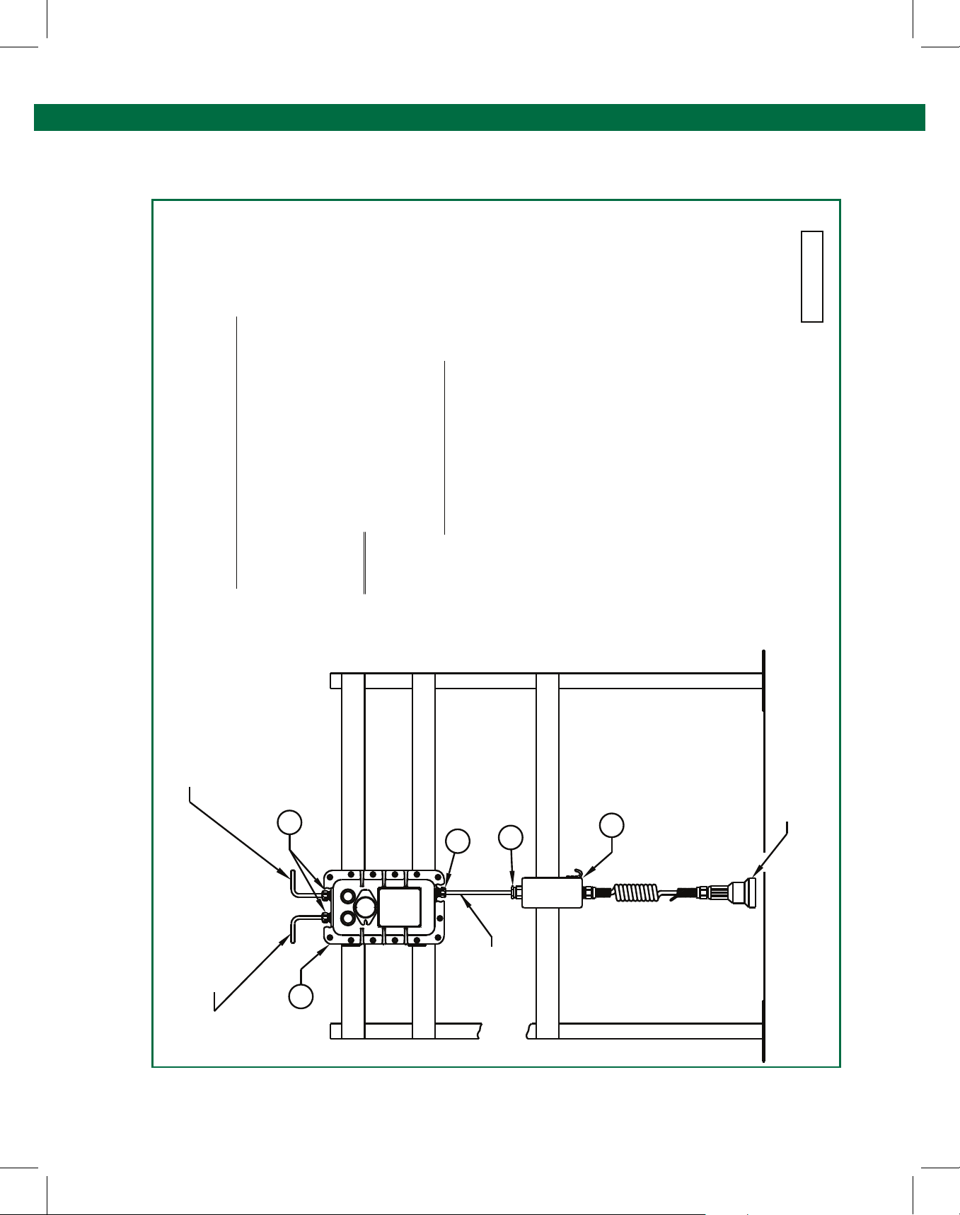
mounted vertically, in a location where the cover can open for servicing. (See Diagram 61442 in
Appendix 4 for installation.)
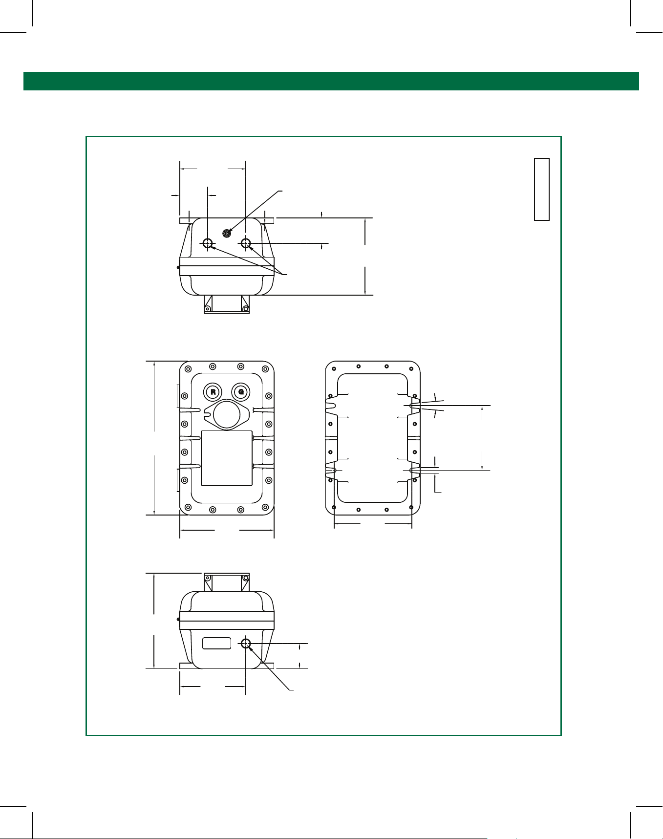
Refer to the Outline Drawing 31412 in Appendix 4.1 for physical dimensions, location of the
mounting bolts, electrical cable/conduit entry locations and enclosure earth bonding stud. The
enclosure earth-bonding stud is provided for proper electrical bonding (earthing) of the enclosure to
earth (ground). Use only the three conduit entry holes provided for wiring. The top two holes
are for power and control wiring. The bottom hole is for intrinsically safe sensor wiring only.
Do not drill any additional conduit holes in the enclosure; doing so violates the enclosure’s
hazardous location approval and voids the warranty.
To avoid future maintenance issues regarding water inltration into the enclosure via the electrical
cable entries, we strongly recommend the following precautions:
1. Minimize long vertical cable (or conduit) runs into the top of the enclosure as long vertical
runs promote water channeling to the cable gland.
2. The cable glands at the top of the enclosure should be very carefully installed, taking
extra precaution to make certain that the installation is proper and sealed (as required by
code).
3. Must seal all enclosure cable gland entries to maintain IP65 rating and protect
against water inltration. Install a ber washer between the cable gland and the
enclosure.
2.2 Electrical Installation
Refer to the Installation Wiring Diagrams in Appendix 4.
All cable entry ttings, junction boxes, connections, wiring, etc. are to be provided by the installer.
Explosion-proof cable glands must be employed for cable entry. If conduits are used for cable
entry, seal ttings must be installed in each conduit (See Wiring Diagram 61145).
Page 8.
Page 9

Multiple Point Overll Prevention Control Monitor
Installation
There are three holes in the enclosure for cable entry. Two holes in the top of the enclosure are for
mains power and control output wiring. One hole in the bottom of the enclosure, labeled
“Intrinsically Safe Entry” is for connection to sensors, via a Scully Sculcon Junction Box and Plug &
Cable.
WARNING: The electrical cable entry in the bottom of the enclosure marked “INTRINSICALLY SAFE
ENTRY” must only be used for wiring to the sensors (via plug and cable assembly). To maintain
intrinsic safety, this cable entry must not be used for any other wiring. DO NOT ROUTE MAINS
POWER THROUGH THIS HOLE.
2.2.1 Power Connections
Route the mains power wires through the top left-hand entry hole in the top of enclosure. Connect
mains power wires to appropriate terminals on terminal block (strip) on the metal bracket in the
enclosure. The Power terminals are marked E, N, & L, also shown in wiring diagram.
NOTE: The ST-35C Control Module is protected by a fuse (F1) in the enclosure located next to the
terminal strip on metal bracket. See replacement part in appendix 4.9 or 4.10.
2.2.2 Enclosure Earth (Ground) Connection
Connect a wire (1.5mm
structure of the gantry (rack).
2.2.3 Control Output (Controlled Circuit) Connections
Route the control output wiring through the top right hand entry hole in the enclosure and connect
to output contact terminals, indicated on the terminal strip on metal bracket. The output control
contact is open when no connection from the controller is made to a vehicle (idle state). The output
control contact closes when all of the optic sensors connected to the control unit are dry and
functional (or when optional bypass switch is in the “Bypass” position).
The contact opens if a sensor gets wet (i.e. detects liquid). The contact also opens in case of a fault
in any sensor, wiring to the sensors or a fault within the control units’ circuitry.
NOTE: An internal fuse (F2) protects the output relay contact, located on metal bracket.
See replacement part in appendix 4.9 or 4.10.
The output contact is rated 250VAC, 5A resistive maximum. It is used to close a valve or pump
directly or by wiring it in series with other control contacts, such as a preset meter’s control
contacts. (See diagram 61441, Typical Loading Rack Control in Appendix 4) In addition it may
also be connected to an input of a terminal automation system (TAS) to provide status of the
controller’s output to TAS.
2
or 16 AWG minimum) from the enclosure-bonding stud to earthed metallic
Caution: A valve or pump should be directly controlled by ST-35C’s relay output
contact. It should not go via the logic circuits of a TAS, as that can introduce
unsafe failure modes into this emergency shutdown system. TAS may also
control a valve or pump based on other conditions.
!
Page 9.
Page 10

ST-35C - Technical Manual
Installation
2.2.4 Intrinsically Safe Connections to Sculcon Plug & Cable Unit
Signals from ST-35C to Sculcon Plug & Cable Unit are intrinsically safe. The intrinsically safe
connections must only be made via the entry hole in the bottom of the enclosure. The connections
are made to the terminal strip TB2 at the bottom end of the printed circuit board module. The wires
must be 1.0mm
wiring diagram 61145 (see Appendix 4). Use wire colors as indicated (red, black, yellow and
orange). If other than suggested color codes are used, this information should be so noted in the
back of this manual for future reference and troubleshooting. All wiring installation should be in
accordance with local wiring codes.
2.3 Initial System Checkout
2.3.1 Test Equipment
Scully suggests the use of our Universal Loading Rack Tester Model ST-2-DSWJ for
individual compartment checks, cable continuity or oat detection. The tester will expedite
the initial system check out of the ST-35C. While not required, the tester provides all of the
proper overll prevention system signals to verify the new installation without the need to
secure an actual vehicle for testing.
2
(18AWG) minimum conductor size. Connect 4 wires to Sculcon as shown in the
2.3.2 Operational Testing
Apply power to the ST-35C control unit.
The red light should be ON, provided Bypass Control Switch is in NORMAL position.
Check status of lights with Bypass Control Switch in the following positions:
OFF: Both lights should be OFF
NORMAL: Red light should be ON
BYPASS: Both lights should be OFF
Set Bypass Switch to NORMAL position, the normal operation setting. The Bypass Switch
should be kept under a lock (user provided) so that its’ setting cannot be tampered with,
without proper authorization.
Connect Sculcon plug to socket on the tester. Follow instructions provided with the tester.
As the tester simulates a vehicle equipped with 5-wire sensors, the ST-35C output will go
permissive immediately with green light ON and red light OFF.
Follow instructions provided with the tester to test both permissive and non-permissive
states of the ST-35C controller.
Page 10.
Page 11

Multiple Point Overll Prevention Control Monitor
Installation
2.4 System Operation
Connect the Sculcon plug to socket on the vehicle to be loaded. If all sensors are dry, the ST-35C
controller will go PERMISSIVE immediately (i.e. green light ON). The output relay contact closes
enabling the loading to begin. If there is a fault in the sensor, wiring interconnections or the
controller circuitry the controller output will stay NON-PERMISSIVE (does not allow loading to
begin). If a fault develops during loading or liquid level reaches the sensor, the controller will switch
to NON-PERMISSIVE (i.e. red light ON and output relay contact opens).
Disconnect Sculcon plug from the socket after the loading is complete. Hang the plug on the hook
provided on the Sculcon junction box (or in Scully Plug Storage Hanger socket).
Page 11.
Page 12

ST-35C - Technical Manual
Maintenance
CAUTION: BEFORE PERFORMING ANY MAINTENANCE ON THE CONTROL UNIT,
DISCONNECT POWER TO THE ST-35C AND WAIT UNTIL THE AREA IS
KNOWN TO BE CLEAR OF ANY EXPLOSIVE GAS, BEFORE OPENING.
ALWAYS REPLACE ALL BOLTS WHEN REINSTALLING THE COVER.
3.1 Enclosure
Considering the location where the control unit will be typically mounted, it is advisable to inspect
the enclosure routinely for deterioration due to environmental corrosion. The control unit should be
opened once per year for internal inspection and replacement of the corrosion (inhibitor) capsule.
Cover screws used must be minimum grade A2-70 stainless steel.
3.2 Corrosion Protection
The control unit is shipped from the factory with a corrosion inhibitor capsule adhered to the inside
of the cover. The corrosion capsule is designed to condition the atmosphere within the enclosure to
resist corrosion. It is intended to last approximately 1 year in normal use. As previously mentioned,
the control unit should be opened once per year for internal inspection. At this time the corrosion
capsule should be replaced (see Replacement Parts Sheet in Appendix Section 4.9 or 4.10).
!
It is also recommended to replace the cover O-ring at the same time.
3.3 Control Module (Circuit Board)
The ST-35C control unit’s internal circuitry does not require any routine periodic maintenance.
The control circuitry may be repaired only by replacing the internal control module with an
equivalent module. The internal module is non-repairable.
DO NOT ATTEMPT TO SERVICE OR ADJUST THE ST-35C MODULE. ATTEMPTING TO
SERVICE THE MODULE WILL NEGATE WARRANTIES, CERTIFICATION AND
JEOPARDIZE INTRINSIC SAFETY ASPECTS OF THE DEVICE.
If it is determined (after troubleshooting, see Section 3.8) that control module needs to be replaced,
remove the faulty control module and install the replacement control module per the following
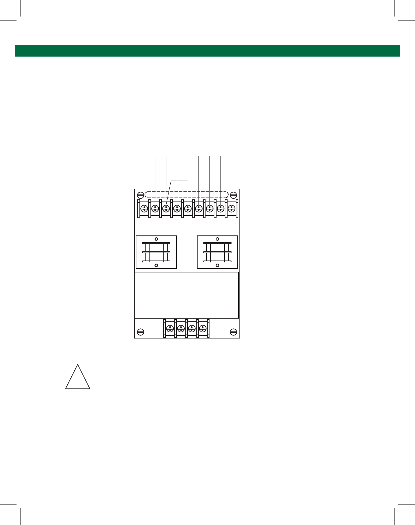
steps: (See Figure 1 ST-35C Control Module Illustration on following page)
!
3.4 Module Replacement
REMOVING THE MODULE
1.Make sure the work area is not hazardous, by ensuring there is no hazardous gas or
materials.
2. Remove (disconnect) power from the ST-35C Control Unit.
3. To open the ST-35C Control Unit cover, remove the (16) hex socket head bolts by using a
6mm hex wrench.
4. Mark/label wires connected to TB1 on printed circuit board (to be able to reconnect to
the same terminal numbers on the replacement module).
5. Disconnect all wires connected to TB1.
6. Mark/label wires connected to TB2.
7. Disconnect all wires connected to TB2.
8. Remove the Control Module assembly by loosening the four-(4) mounting screws located
in the four corners of the Control Module assembly.
Page 12.
Page 13
Multiple Point Overll Prevention Control Monitor
Maintenance
INSTALLING REPLACEMENT MODULE
1. Place the new Control Module onto the mounting plate and attach the (4) mounting
screws.
2. Reconnect the wires to TB2.
3. Reconnect the wires to TB1.
4. Close the cover and attach the (16) cover bolts.
5. Apply power to the Control Unit.
R
B
E
G W
R H
N T
L
K
B
D
L
K
E R
L N
BY
O
R
N
2
31
4
5
6
7
8 9
TB1
Figure 1: ST-35C
Control Module Illustration
ST-35C CONTROL MODULE
1 2 3 4
TB2
Note: The ST-35C Replacement Control Module cannot be repaired in the eld. A damaged
or faulty module must be replaced with an equivalent Scully ST-35C Control Module. The
ST-35C Replacement Control Module must only be installed in Scully’s explosion-proof
enclosure. The enclosures’ explosionproof and weatherproof integrity must be maintained.
!
The ST-35C Control Module should not be subjected to any mechanical impact. Do not allow
build-up of dust on the Control Module.
Caution: Do not expose the Control Module to aggressive substances that may attack the exposed
materials.
When used properly, contact with the control module will not cause physical injury or harm and
does not pose non-electrical dangers. The unit does not produce excessive surface temperatures,
or emit infrared or ionizing radiation.
Page 13.
Page 14
ST-35C - Technical Manual
Maintenance
3.5 Indicator Lights
The control unit employs explosion-proof LED style lights. These do not require any maintenance or
changing of bulbs. In the event a light is faulty, it must only be replaced with parts numbers shown
in Replacement parts Sheet in Appendix 4.9 or 4.10. Follow instructions provided with the
replacement indicator lights (pilot lights).
Note: Older ST-35C Controllers employed incandescent style lights. These require replacement of
bulb if it blows. Refer to Replacement Parts Sheet in Appendix 4.9 or 4.10.
3.6 Control (Bypass) Switch
On those models having a lockable control (Bypass) switch, the switch box may be replaced by
removing two screws inside the switch box. The switch box is replaced as a unit.
A faulty switch may also be replaced if necessary, see replacement parts sheet in Appendix 4 for
replacement part numbers.
3.7 Junction Box and Plug & Cable Unit
The Sculcon Junction Box and Cable unit(s) require simple routine maintenance. More attention is
needed in highly corrosive environments.
Although it is not required, we recommend that the exposed electrical contact of the plug be
coated with a corrosion inhibiting lm routinely (once per month is suggested). Corrosion inhibiting
spray, ACF-50 Corrosion Block® (manufactured by Lear Chemical Research Corporation,
Mississauga ON Canada www.learchem.com). Other external metal parts of these accessories may
also be treated as necessary to prevent atmospheric corrosion problems.
The exterior surface of the plug should be kept clean using a mild detergent based cleaning
solution and water. The cabling should be routinely wiped of foreign material and cleaned to
preserve the outer jacket. To protect it from loading arm damage etc., it is important to store the
plug and cable out of harms way when it is not in use. A hook is provided on Sculcon Junction Box
or a Scully Storage Socket may be used.
3.8 Fuses Replacement Description
(Also see replacement Parts Sheet in Appendix 4.9 or 4.10.)
Fuse Description Part Number
F1 1A, 250V, 1” X 1/4”, 6000A Breaking Capacity 26343
F2 5A, 250V, 1” X 1/4”, 6000A Breaking Capacity 26350
Page 14.
Page 15

Multiple Point Overll Prevention Control Monitor
Maintenance
3.9 Troubleshooting
The following troubleshooting guide should aid in an initial diagnosis of most problems encountered
with installation and operation of ST-35C.
Condition
No lights ON, on front cover
Green (Permissive) light ON, but
control contact output does not
activate valve/pump
Red (Non-permissive) light stays ON
when connected to vehicle with
Scully 5-wire sensors (or Scully
tester)
Red LED on Control Module (circuit
board) ON but Green external light
OFF
Possible Cause
• No power to control unit
• Control (Bypass) Switch in OFF position
• Bulb blown (on older units with incandescent lamps)
• Input power fuse (F1) is blown
• Control Module is defective
• Control (Bypass) Switch in BYPASS position
• Control Output fuse (F2) is blown
• Wiring defect (control output contact wiring)
• Control Module is defective
• Wet or faulty sensor on vehicle
• Fault in wiring to junction box and/or plug
• Fault in wiring on vehicle
• Bad plug to socket connection
• Control Module is defective
• Internal wiring fault
• Control Module is defective.
• Green external light defective
Red LED on Control Module (circuit
board) OFF
Check voltage (DC) between pins 8 and 10 (ground) of the plug. It should be 8.7VDC minimum.
• No power to control unit
• Control (bypass) Switch in OFF position
• Input power fuse (F1) is blown
• Wet or faulty sensor
• Fault in wiring to sensors
Page 15.
Page 16
ST-35C - Technical Manual
Diagram Appendix
4.1 DWG 31412 – Outline Drawing – Control Unit Enclosure
5.87
(149.0)
2.47
(62.7)
TOP VIEW
ENCLOSURE EARTH
BONDING STUD
2.00
(50.8)
6.62
(168.1)
SEE NOTE 2
31412 RevC
13.69
(347.7)
8.38
(212.9)
G
R
scully
8.44
(214.3)
FRONT VIEW
INTRINSIC
SAFE
ENTRY
6.75
(171.5)
(MOUNTING LUG CENTERS)
REAR VIEW
NOTES:
1. DIMENSIONS ARE IN INCHES WITH MILLIMETERS
IN PARENTHIESS.
2. ENTRY HOLES:
2.25 (57.1)
10°, 4 PL
5.75
(146.0)
(MOUNTING LUG CENTERS)
.50
(12.7)
FMC APPROVED MODELS: 3/4" NPT
ATEX APPROVED MODELS: M20 X 1.5
Page 16.
5.87
(149.0)
BOTTOM VIEW
SEE NOTE 2
Page 17
Multiple Point Overll Prevention Control Monitor
Diagram Appendix
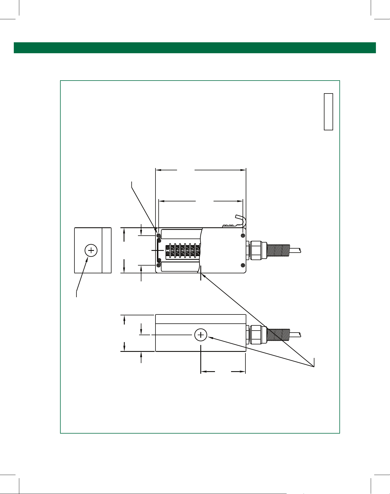
4.2 DWG 63039 – Outline Drawing – Sculcon Junction Box
63039 RevF
MOUNTING CENTERS FOR
#8 (4) HEX SOCKET
HEAD SCREWS (4 PLACES)
3.94
(100.0)
2.58
(65.5)
3.20
(81.3)
7.87
(200.0)
1
5 63 42
7.33
(186.2)
MILLIMETERS IN PARENTHIESS.
1. DIMENSIONS ARE IN INCHES WITH
NOTES:
Ø1.06 (27) HOLE FOR
CONDUIT HUB (CABLE GLAND)
1.44
(36.6)
3.94
(100.0)
CONDUIT HUB (CABLE GLAND)
Ø1.06 (27) KNOCKOUT FOR
Page 17.
Page 18

ST-35C - Technical Manual
Diagram Appendix
4.3 DWG 61441 – Wiring Diagram – Typical Loading Rack Control
TO OTHER
SET-STOP
METERS ON
SAME RACK
SV
HI FLOW
HI FLOW
LO FLOW
SV
LO FLOW
SOLENOIDS
PILOT CONTROL
LOADING VALVE
CONTACTS
VALVE CONTROL
SET-STOP METER
CARD READER
PERMISSIVE CONTACTS
61441 RevC
TO OTHER
LOADING RACK
4 5
HOT
5A
SHUTDOWN
TERMINALS
SWITCH OR
EMERGENCY
MAINS
POWER
OUTPUT CONTACT
SCULLY CONTROL UNIT'S
RELAY
NEUT
IN CIRCUIT TO LOADING VALVES.
TYPICAL LOADING RACK CONTROL SHOWING PERMISSIVE CONTACTS
NOTE: WIRING SHOWN IS TYPICAL AND WILL VARY AS MORE OR LESS EQUIPMENT IS EMPLOYED.
PUMP CONTROL CIRCUITS NOT SHOWN. THIS DIAGRAM IS INTENDED TO BE USED ONLY TO
CLARIFY USE OF CONTROL CONTACTS. ALL CONTACTS SHOWN IN NON-PERMISSIVE STATES.
Page 18.
Page 19
Multiple Point Overll Prevention Control Monitor
Diagram Appendix
4.4 DWG 61442 – Mounting Diagram – Control Unit & Junction Box
61442 RevC
EQUIPMENT SCHEDULE (TYPICAL)
1. CONTROL UNIT
(PLUG HOLE IF NOT USED)
ALTERNATIVE ENTRY FOR
OUTPUT CONTROL WIRING
IF CONDUITS ARE USED FOR CABLE ENTRY, SEAL FITTINGS
2. SCULCON JUNCTION BOX WITH PLUG AND CABLE.
3. FLAMEPROOF Exd CABLE GLAND FITTING.
IMPORTANT: INTRINSICALLY SAFE AND NON-INTRINSICALLY SAFE
MUST BE INSTALLED WITHIN 18 INCHES OF AN
EACH CONDUIT (NOT SHOWN).
EXPLOSION-PROOF ENCLOSURE IN A HAZARDOUS LOCATION, IN
4. INDUSTRIAL CABLE GLAND FITTING.
WIRING MUST ALWAYS BE SEPARATED AND
RUN IN SEPARATE CONDUITS/CABLES.
3
INSTALLATION NOTES
INTENDED TO REPRESENT CODE COMPLIANCE.
DETAILS SHOWN ARE FOR REFERENCE ONLY AND ARE NOT
REGULATIONS FOR INSTALLATIONS IN HAZARDOUS LOCATIONS
1. INSTALLATION MUST COMPLY WITH NATIONAL AND LOCAL
3
2. THE INTRINSICALLY SAFE WIRING BETWEEN THE BOTTOM PORT
4
AND THE CONTROL UNIT ENCLOSURE AT ALL CABLE PORT ENTRIES.
JUNCTION BOX MUST BE RUN USING DEDICATED CABLE
OR IN A CONDUIT. NO OTHER SIGNALS ARE TO BE RUN
OF THE CONTROL UNIT ENCLOSURE AND THE SCULCON
THE CONTROL UNIT ENCLOSURE TO AVOID CONDENSATION CHANNELING.
IN THIS CABLE OR CONDUIT.
4. USE FIBER SEALING WASHERS BETWEEN THE CABLE GLAND FITTINGS
3. MINIMIZE LONG VERTICAL RUNS OF CABLE INTO THE TOP PORTS OF
2
PLUGGED USING A CERTIFIED FLAMEPROOF STOPPER PLUG.
5. ANY UNUSED HOLES IN THE FLAMEPROOF ENCLOSURE MUST BE
OVERFILL PREVENTION SYSTEM ON
PLUG ASSEMBLY TO CONNECT TO
VEHICLE.
MAINS POWER AND OUTPUT
CONTROL WIRING
1
WIRING USING SEPARATE
CABLE
INTRINSICALLY SAFE
Page 19.
Page 20
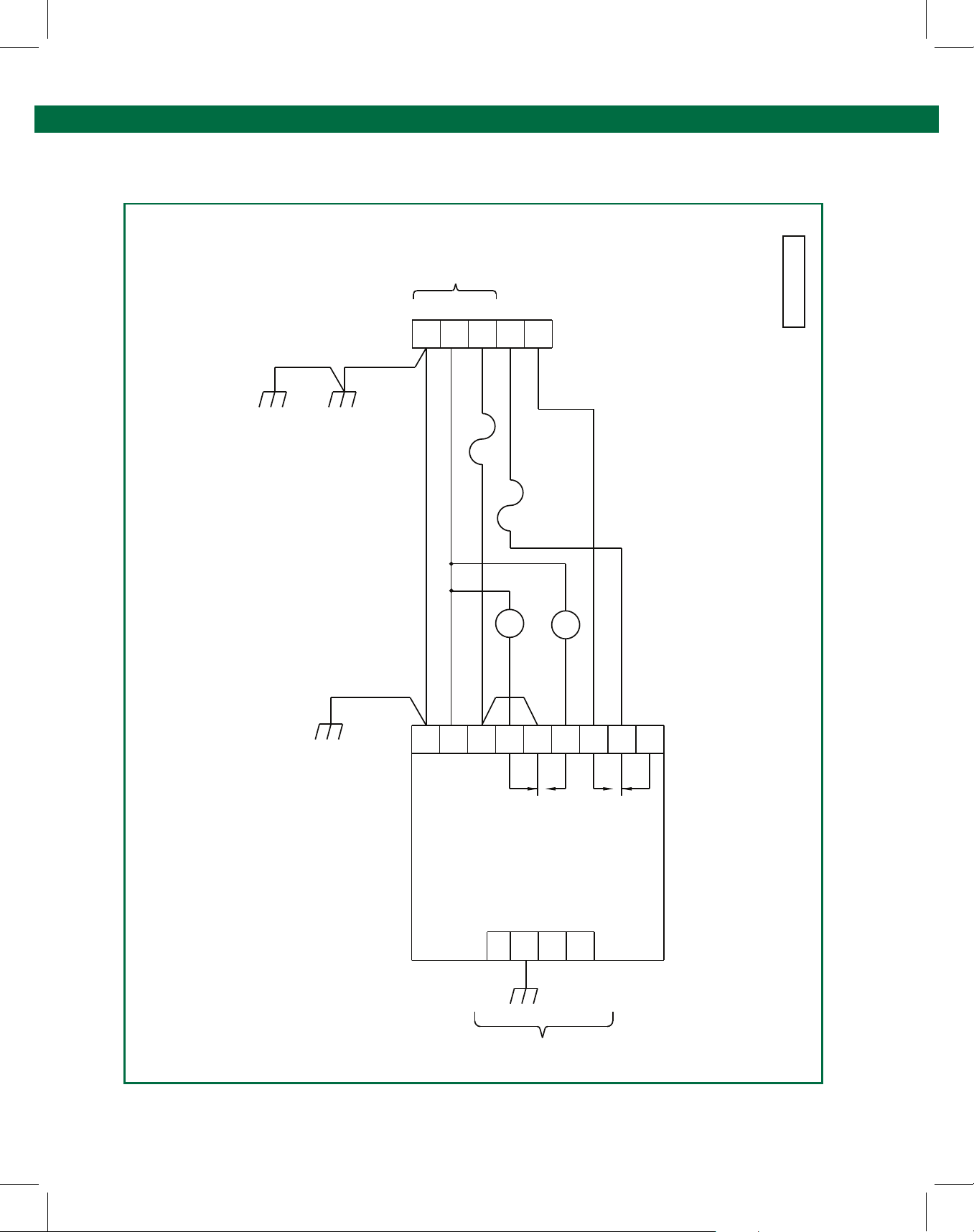
ST-35C - Technical Manual
Diagram Appendix
4.5 DWG 31306 – Internal Wiring Diagram – ST-35C-EL
CONTROL
CONTACTS
RATED 5 AMP
250 VAC
RESISTIVE
L
3
4 5
O
B B
R
L R
N
K
N
1A
F2
GRN
COVER
SCREW
GRN
BASE
SCREW
MAINS
POWER
E N
1 2
W
G
H
R
T
N
F1
31306 RevC
TB1
GRN
PANEL
SCREW
G W
R H
N T
2
5A
L2
R
R
B
E
L
D
K
31
4
E
T
ST-35C
L1
G
O
E R
L N
6
BY
R
N
7
DDW
R
Y
9
8
W
E
T
B
L
K
5
R
Y
Page 20.
31 2 4
WHT
BASE
GROUND
WIRING TO OPTIC SENSOR
Page 21
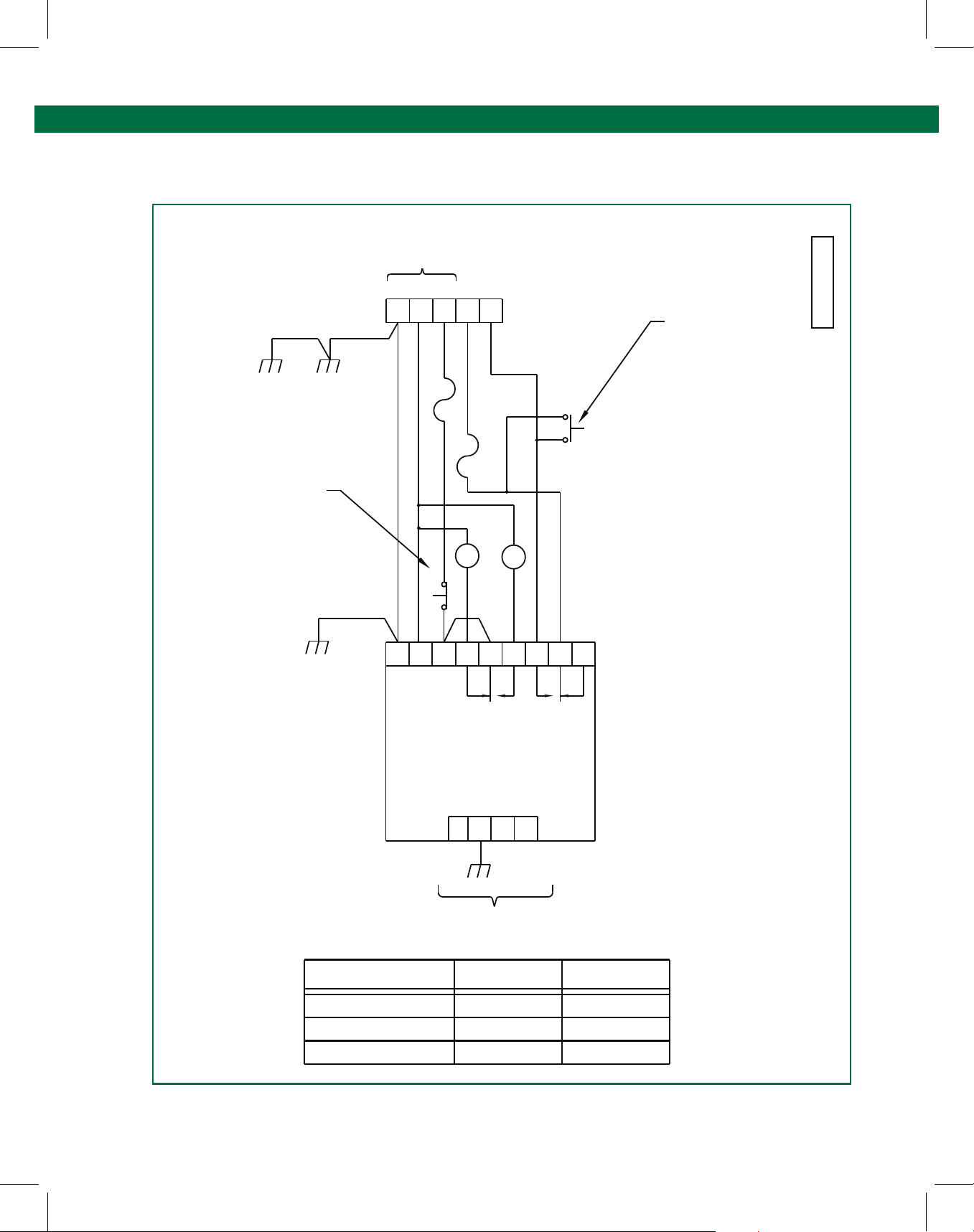
Multiple Point Overll Prevention Control Monitor
Diagram Appendix
4.6 DWG 31307 – Internal Wiring Diagram – ST-35C-ELK
CONTROL
CONTACTS
RATED 5 AMP
250 VAC
RESISTIVE
L
3 4
O
B
R
L
N
K
F1
1A
TB1
5
B
R
N
GRN
COVER
SCREW
GRN
BASE
SCREW
MAINS
POWER
E N
1 2
W
G
H
R
T
N
SEE TABLE
31307 RevC
SEE TABLE
PANEL
SCREW
GRN
G
R H
N T
1
S1A
W
2
F2
5A
L2
R
R
E
D
3
4
W
E
T
ST-35C
2
1 3 4
S1B
L1
G
Y
B
L
K
5
B O
E
L
6
D
R
Y
RR
N N
879
D W
E
YRT
WIRING TO OPTIC SENSOR
POSITION
NORMAL
OFF
BYPASS
WHT
BASE
GROUND
S1A
CLOSED
OPEN
OPEN
S1B
OPEN
OPEN
CLOSED
Page 21.
Page 22
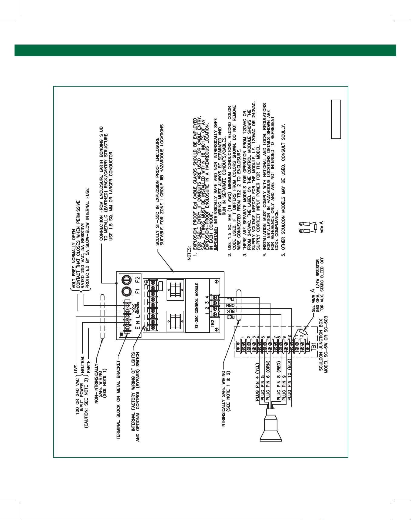
ST-35C - Technical Manual
Diagram Appendix
4.7 DWG 61145– Installation Wiring Diagram
61145 RevD
Page 22.
Page 23
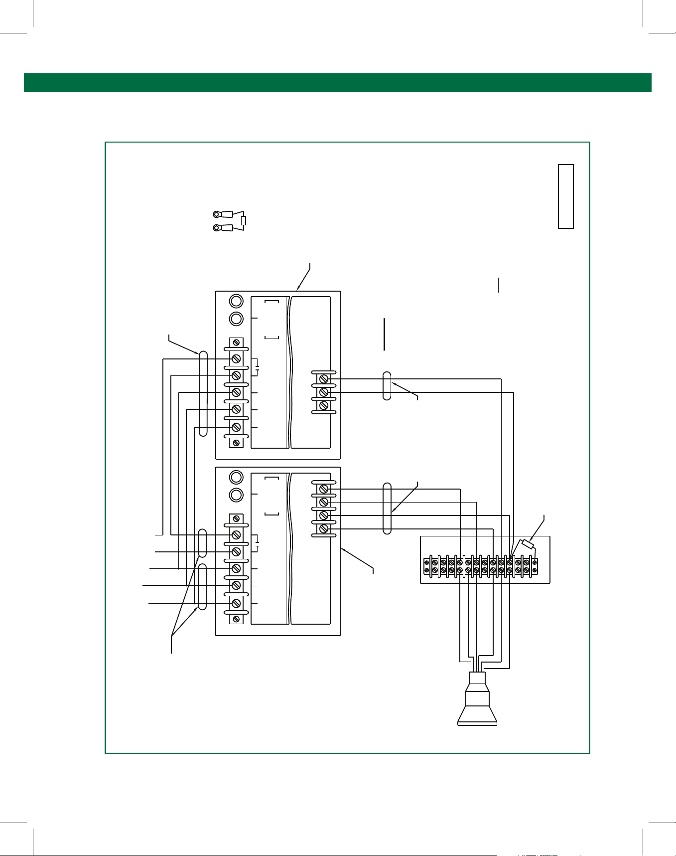
Multiple Point Overll Prevention Control Monitor
Diagram Appendix
4.8 DWG 61406– Installation Wiring Diagram, ST-35C/ST-47C
NON-INTRINSICALLY
250 VAC, 5A RESISTIVE
CONTACTS THAT CLOSE ON PERMIT
}
SAFE WIRING
(SEE NOTE 1)
F2F2
F1
TB1
F1
A
VIEW
FUSES
CONTROL
NEUT LIVE
EARTH
FUSES
F1 = 1A
F2 = 5A
CONTACTS
RATED 5 AMPS
250 VOLTS MAX
MAINS POWER
F1 = 1A
F2 = 5A
A ZONE 1, GROUP IIB HAZARDOUS LOCATION.
LOCATION OR SCULLY ST-47CE MOUNTED IN
SCULLY ST-47C MOUNTED IN A SAFE
3
2
GROUNDHOG
1
ST-47C-120/240 E(LK)
TB2
YEL
ORN
BLK
RED
NOTES:
1. IMPORTANT: INTRINSICALLY SAFE AND NON-INTRINSICALLY
SAFE WIRING MUST ALWAYS BE SEPARATED AND
RUN IN SEPARATE CONDUITS.
COLOR OF WIRES SHOULD MATCH CONTROLLER TERMINAL COLORS-
2. WIRE TO BE 18 AWG MINIMUM, STRANDED AND TINNED.
INTRINSICALLY SAFE WIRING
IF POSSIBLE. IN ALL CASES WIRING MUST MEET APPLICABLE
NATIONAL, STATE AND LOCAL CODES.
(SEE NOTES 1 & 2)
FOR DETAILS.
THROUGH THE ST-35C OR ST-47C HOUSINGS. UNDER NO
BOXES. CONTROL (NON I.S.) WIRING MUST PASS IN AND OUT OF
CIRCUMSTANCES, ARE THE HOUSINGS TO BE USED AS JUNCTION
4. INTERCONNECTION WIRING MUST NOT BE ALLOWED TO PASS
3. OTHER SCULCON MODELS CAN BE USED. CONSULT FACTORY
WIRING MUST EXIT ONLY FROM THE BOTTOM CONDUIT ENTRY.
THE TOP CONDUIT ENTRY PORTS AND INTRINSIC SAFE (I.S.)
WHT
ORN/BLK
A
560 OHM, 1/4W RESISTOR
SEE VIEW
61406 RevB
FOR AUX. STATIC BLEED-OFF
120/240 VAC
INPUT
NEUT
EARTH
LIVE
SAFE WIRING
(SEE NOTE 1)
NON-INTRINSICALLY
TB1
CONTROL
CONTACTS
LIVENEUT
MAINS POWER
EARTH
RATED 5 AMPS
1
4
250 VOLTS MAX
TB2
2
635
978
10
12
11
TB1
(SEE NOTE 3)
SCULCON BOX
MODEL SC-6AO OR 6W
ST-35C-120/240 E(LK)
PLUG PIN 8 (BLU)
PLUG PIN 10 (WHT)
PLUG PIN 9 (ORN/BLK)
TANKER
CONNECTOR PLUG
SCULLY ST-35C MOUNTED IN A SAFE
LOCATION OR SCULLY ST-35CE MOUNTED IN
A ZONE 1, GROUP IIB HAZARDOUS LOCATION.
PLUG PIN 4 (GRN)
PLUG PIN 6 (ORN)
PLUG PIN 5 (RED)
Page 23.
Page 24
ST-35C - Technical Manual
Diagram Appendix
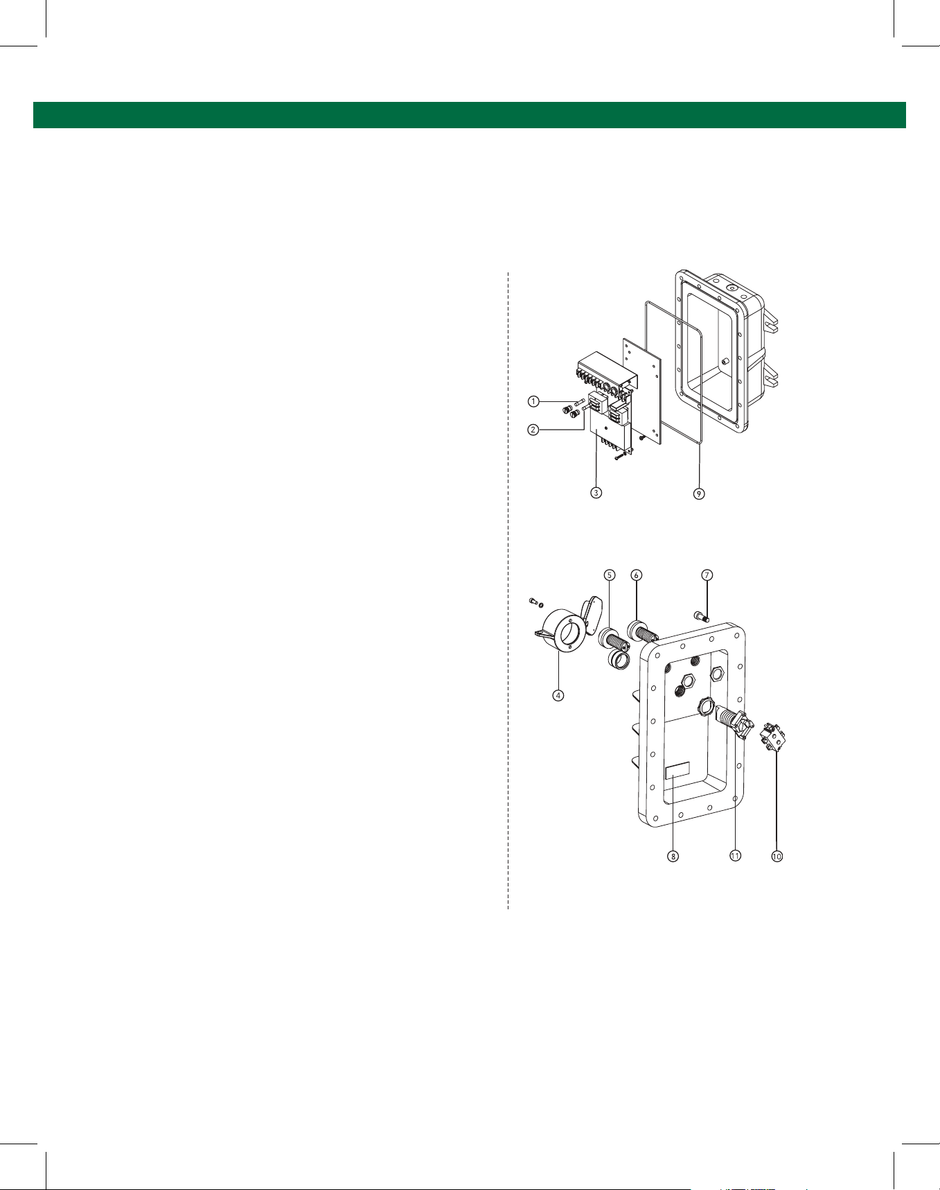
4.9 DWG 61559 – Replacement Parts ST-35C-120 VAC
ST-35C 120VAC
Multi-Point Optic Controllers
CENELEC Models
Part No. Model
08811 ST-35C-120 EL
08807 ST-35C-120 ELK
Note: Controller Models Sufx:
Explosion-proof housing (E), Indicator Lights (L), Key (K) Lockable
Bypass Switch.
Replacement Parts
.ytQnoitpircseD.oN traP metI
1 26343 Main Fuse, 1 Ampere, 1” X 1/4” 1
2 26350 Control Fuse, 5 Ampere, 1” X 1/4” 1
3 08808 ST-35C-120 Module Assembly, 120 1
4 08360 Bypass Switch Lockbox 1
5 09220 Replacement Light Explosion Proof 1
6 09221 Replacement Light Explosion Proof 1
7 50005 Socket Head Cap Screw, Stainless 16
10 26022 Bypass Switch Contact Block 1
11 26055 Bypass Switch Operator 1
* 27085 Bulb, 120V, 6W*
(includes 2 mounting screws)
Lamp Assembly, Green, LED Style
Lamp Assembly, Red LED Style
laes revoc gnir-O043139
3 Position
1eluspaC noisorroC337128
1
Page 24.
Notes:
Item 7: New socket head screw used on models built after 10/92.
Item 9: O-ring used on models built after 10/92.
Item 5, 6: LED style lamps used on models built after 2/02.
* Replacement bulb for incandescent style explosion-p
Use on models build prior to 2/02.
roof lights.
61559, Rev B 2003
Page 25
Multiple Point Overll Prevention Control Monitor
Diagram Appendix
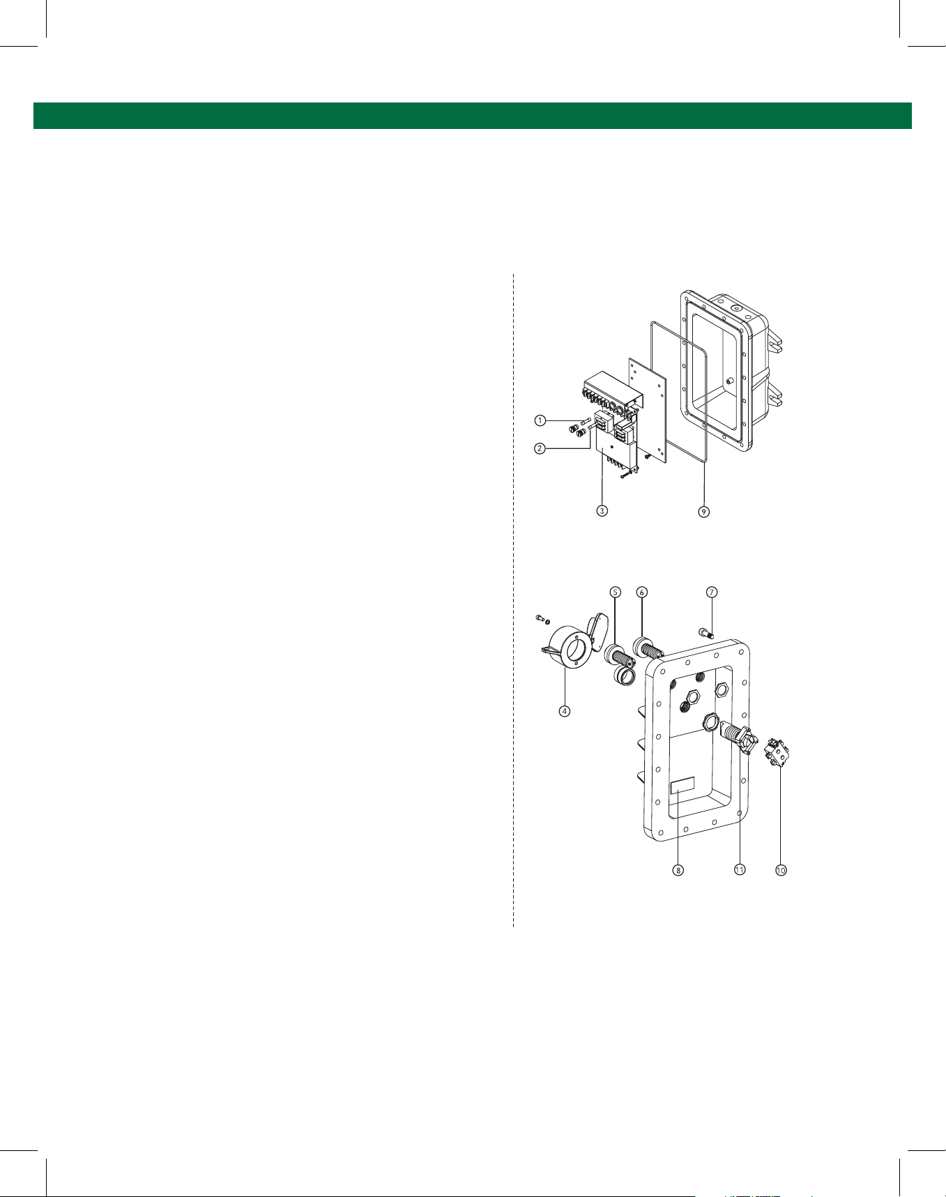
4.10 DWG 61224 – Replacement Parts ST-35C-240 VAC
ST-35C 240VAC
Multi-Point Optic Controllers
CENELEC Models
Part No. Model
08623 ST-35C-240 EL
08621 ST-35C-240 ELK
Note: Controller Models Sufx:
Explosion-proof housing (E), Indicator Lights (L), Key (K) Lockable
Bypass Switch.
Replacement Parts
.ytQnoitpircseD.oN traP metI
1 26343 Mains Fuse, 1 Ampere,
2 26350 Control Fuse, 5 Ampere,
3 08647 ST-35C-240 Module Assembly,
4 08360 Bypass Switch Lockbox 1
5 09420 Replacement Light Explosion Proof 1
6 09421 Replacement Light Explosion Proof 1
7 50005 Socket Head Cap Screw, Stainless 16
10 26022 Bypass Switch Contact Block 1
11 26055 Bypass Switch Operator, 3 Position 1
(includes 2 mounting screws)
Lamp Assembly, Green, LED Style
Lamp Assembly, Red LED Style
1” X 1/4” 1
1” X 1/4” 1
1V042
1eluspaC noisorroC337128
1laes revoc gnir-O043139
* 27065 Bulb, 240V, 6W*
Note:
Item 7: New socket head screw used on models built after 10/92.
Item 9: O-ring used on models built after 10/92.
Item 5, 6: LED style lights used on models:
a. ELK built after 8/01.
b. EL built
* Replacement bulb for incandescent style explosion-proof lights only.
Use on models:
a. ELK built prior to 8/01.
b. EL built prior to 10/01.
after 10/01.
61224, Rev C 2003
Page 25.
Page 26

Notes:
Page 26.
Page 27

Page 28
Scully - Setting Standards in Safety and Dependability since 1936.
For over seventy-ve years Scully has been engineering and building products to
the highest safety and reliability standards. We design and manufacture all of our
systems under one roof to ensure complete quality control over our manufacturing
and testing operations. Scully is ISO certied and all of our products are 100%
made in the U.S.A. In addition, we back up our products with the best service in
the industry. We have direct sales and service personnel in the U.S.A., The United
Kingdom, and Europe and are represented in over 50 countries.
For more information and 24 hour technical assistance,
call Scully Signal Company at 1-800-SCULLY (1-800-272-8559).
Scully Headquarters in Wilmington, MA U.S.A.
Copyright © 2018 Scully Signal Company. MaxSafety, Sculcon and Scully are registered
trademarks of Scully Signal Company. The names and logos of other companies mentioned
herein may be trademarkes of their respective owners. This document is for informational
purposes only. Scully makes no warranties, expressed or implied, in this document. All Rights
Reserved. Specications are subject to change without notice.
Scully Signal Company
70 Industrial Way
Wilmington, MA 01887, USA
800 272 8559 • [email protected]
Dynamic Self-Testing® Overll Prevention Systems
Scully Systems Europe NV
Maanstraat 25
2800 Mechelen, Belgium
+32 (0) 15 56 00 70 • [email protected]
61109 Rev F
August 2019
Scully UK Ltd
Meridian House, Unit 33
37 Road One Winsford Industrial Estate,
Winsford Cheshire CW7 3QG, UK
+44 (0) 1606 553805 • [email protected]
 Loading...