

Page 1
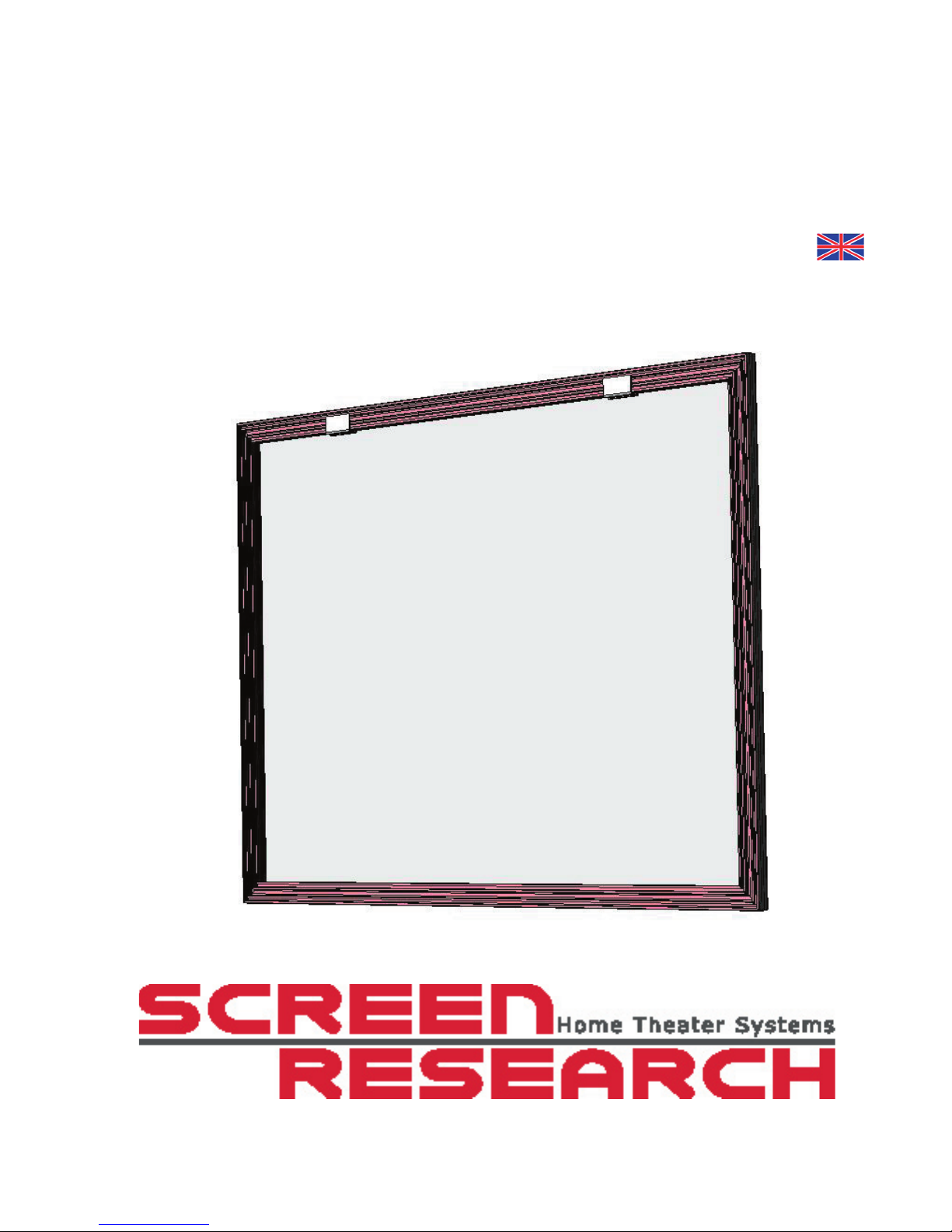
SolidPix™ Fixed-Frame Screen
Integrated Type I
Installation Manual
Revision A 2007.02.22
Page 2

Page 3
SolidPix1™ Integrated Type I Fixed-Frame Screen Installation Manual
3
Revision A 2007.02.22
©Screen Research 2006
Action:
W: Written
R: Page revised
A: Page added
D: Page deleted
C: Rewritten completely
Date Rev. N°Action Rev.
Pages
New
Pages
Reason For Revision
2007.02.22 A W - New document
Page 4

Page 5

SolidPix1™ Integrated Type I Fixed-Frame Screen Installation Manual
5
Revision A 2007.02.22
©Screen Research 2006
Table of Contents
Package Contents 7
Frame Assembly 11
Projection Screen Material Installation 13
Mounting Dimensions 15
Screen Care 17
Page 6

Page 7
SolidPix1™ Integrated Type I Fixed-Frame Screen Installation Manual
7
Revision A 2007.02.22
©Screen Research 2006
Package Contents
The SolidPix Integrated I Fixed Frame screen is shipped as a kit for on-site assembly. The kit contains the
frame, the projection screen fabric, and the tools and accessories necessary for assembly.
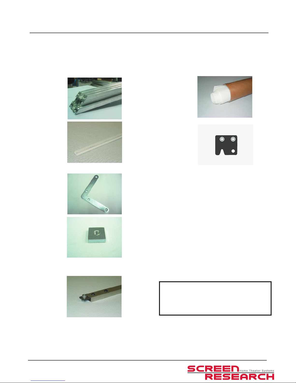
All Fixed-Frame screens include:
Aluminum frame
extrusions
(2 long and 2 short)
Frames larger than
126” are delivered in
8 pieces.
SolidPix projection
Screen Material
(1 piece)
Pi-Grip clipping
extrusion 1m (39”)
(quantity depends on
screen size)
Wall mounting
brackets
(4 pieces)
M6x10 rounded
screws (8pieces + 1
spare)
Ø 6 Rings (8pièces + 1
spare)
Frames larger than
126” are delivered
with 6 wall mounting
brackets.
Flat Corner Brackets
(8 pieces)
3,5 x 25 screws
(16 pieces + 2 spare)
M6 Square nuts
(8 pieces)
In addition, screens larger than 100” wide include:
Frame stiffeners
(2 pieces)
with M6 x 10 bolts
and M6 square nuts
(4 pieces)
Frames larger than
126” are delivered
with 4 stiffeners.
Equipement required (not included) :
- 1 drilling machine
- 1 drill (diam.0,08”/2mm)
Page 8

Page 9
SolidPix1™ Integrated Type I Fixed-Frame Screen Installation Manual
9
Revision A 2007.02.22
©Screen Research 2006
Package Contents
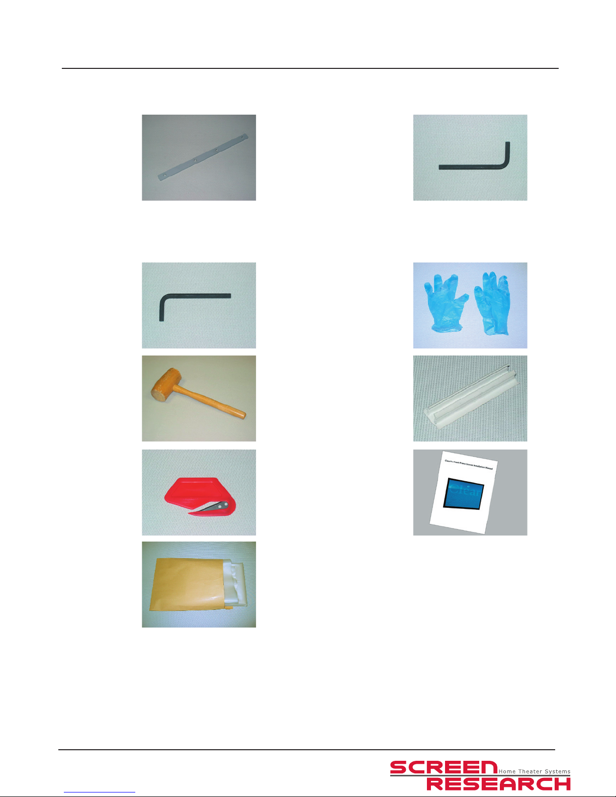
Screens larger than 126” wide are shipped in sections, and also include:
Flat frame extensions
and set screws
(8 pieces)
4mm Allen wrench
(1 piece)
All screens include the following tools for assembly:
6mm Allen wrench
(1 piece)
Gloves
(1 pair)
Mallet
(1 piece)
Short Pi-Grip clipping
extrusions
(12 pieces)
Fabric cutting tool
(1 piece)
Instruction manual
Protective plastic tarp
(1 piece)
Page 10

Page 11
SolidPix1™ Integrated Type I Fixed-Frame Screen Installation Manual
11
Revision A 2007.02.22
©Screen Research 2006
Frame Assembly
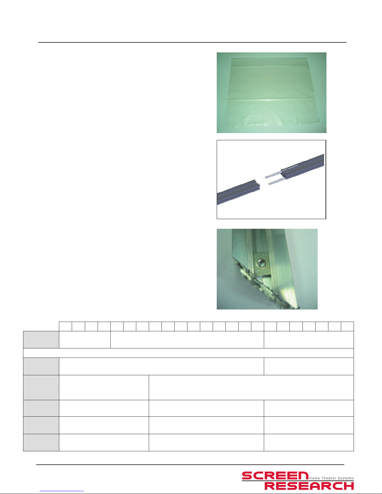
1. Prepare your workspace. You will need an area the
size of the nished screen plus approx 18” / 50cm on
all sides to walk around the screen. A soft surface,
such as carpet, is best if possible.
Roll out the tarp that is provided with the screen to
protect the frame and fabric from foreign matter.
2. If your frame has been delivered in multiple pieces
(generally because it is more than 126” wide),
assemble the three pieces as shown and tighten the
set screws on the back .
3. Insert the square nuts into one of the grooves in the
frame.
To know the number of square nuts you need to
insert, refer to the following table or to the optional
supports installation guides to know how many nuts
you need to put and in which frame section (top or
sides), depending on the frame section you want to
use to attach your screen.
Insert them now as there is no way to add them once
the frame is fully assembled.
70 80 90 96 100 110 120 126 130 140 150 160 170 180 190 200 210 220 230 240 250 260 270
Frame
Stiffeners
2 in the top bar and 2 in the bottom bar
4 in the top bar and 4 in the
bottom bar
TMount
Legs
2 in the left bar and 2 in the right bar
2 in the left bar, 2 in the right
bar and 2 in each stiffener
Standard
mounting
brackets
4 in the top bar and 4 in the
bottom bar
8 in the top bar and 4 in the bottom bar
SCMB
2 per bracket in the desired
frame section
2 per bracket in the desired frame section
2 per bracket in the desired
frame section
RWMB1
4 in the left bar and 4 in the
right bar
4 in the left bar, 4 in the right bar and 2 in
the top bar
4 in the left bar, 4 in the right bar
and 4 in the top bar
RWMB2
4 in the left bar and 4 in the
right bar
4 in the left bar, 4 in the right bar and 2 in
the top bar
4 in the left bar, 4 in the right bar
and 4 in the top bar
Page 12
SolidPix1™ Integrated Type I Fixed-Frame Screen Installation Manual
12
Revision A 2007.02.22
©Screen Research 2006
Frame Assembly
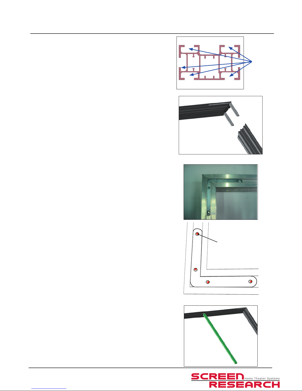
You can install your integrated xed screen as you
want using the different dedicated grooves
4. Insert the at corner brackets into one of the grooves
of the short frame piece.
Repeat for all four at corner brackets.
5. Press the corner tightly together and pre-drill a hole
of 0.08”/ 2mm. The hole should not be centered in
the hole of the bracket but should be slightly away
from the corner of the frame.
6. If your frame came with frame stiffeners, attach them
to the long frame sections using the M6 x 10 bolts
and the square nuts which were inserted in step 3
above.
projection screen
fabric / corner
bracket
Page 13
SolidPix1™ Integrated Type I Fixed-Frame Screen Installation Manual
13
Revision A 2007.02.22
©Screen Research 2006
Projection Screen Material Installation
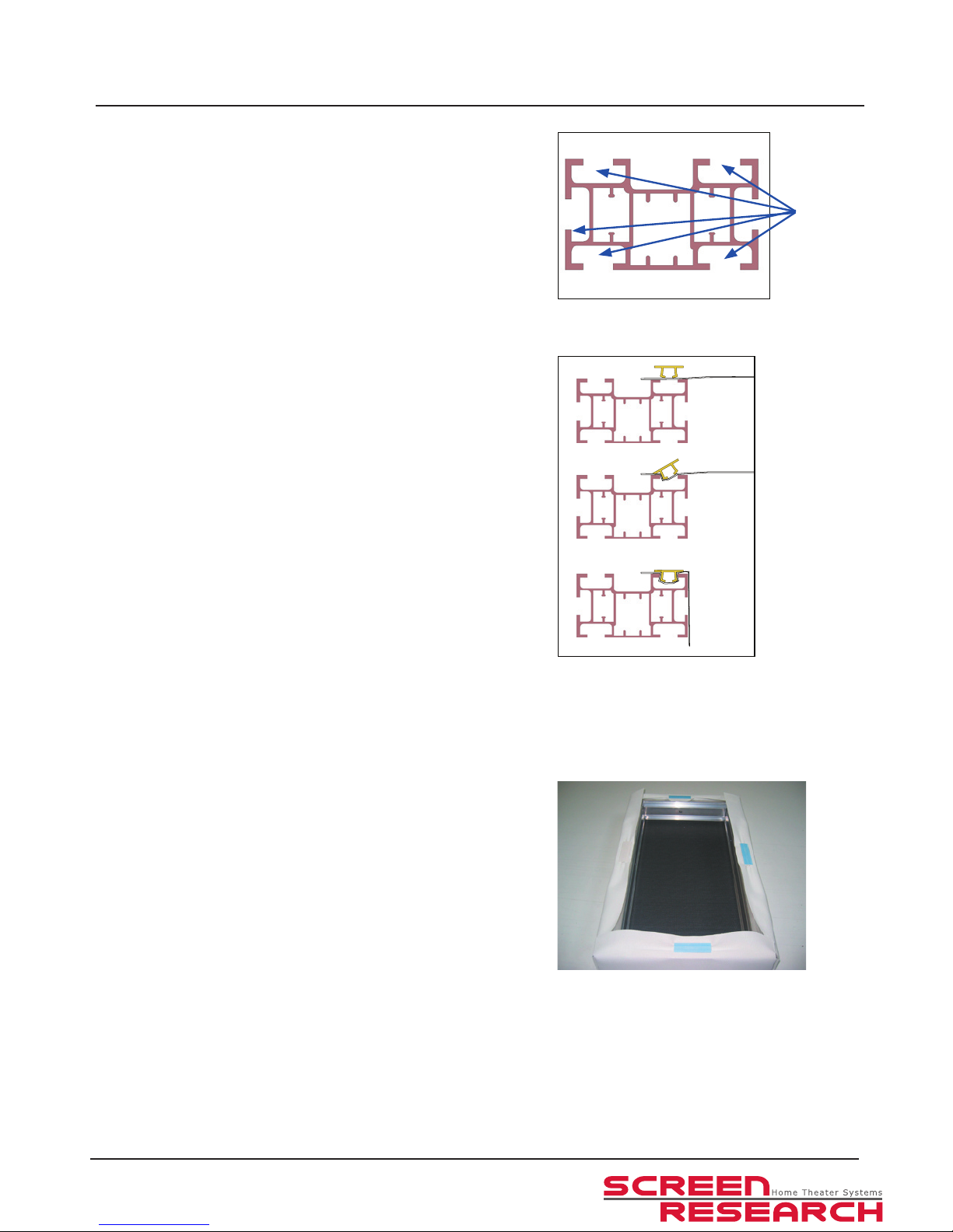
You can install your integrated xed screen as you
want using the different dedicated grooves, in the
following steps we will illustrate one of the many
possibilities.
1. The projection side of the SolidPix projection screen
fabric is indicated by a sticker (in one corner of the
fabric). Clip it in a groove, using a Pi-Grip.
2. Position the projection screen material using the
short (2” / 50mm) pieces of Pi-Grip. Tension the fabric
only slightly at this time.
projection screen
fabric / corner
bracket
Please note that the above picture is concerning a ClearPix2
projection screen fabric. This will soon be replaced with picture for a SolidPix1 projection screen fabric.
Please note, the way of attaching a SolidPix1 projection
screen fabric is the same way of attaching a ClearPix2
projection screen fabric.
Page 14
SolidPix1™ Integrated Type I Fixed-Frame Screen Installation Manual
14
Revision A 2007.02.22
©Screen Research 2006
Projection Screen Material Installation
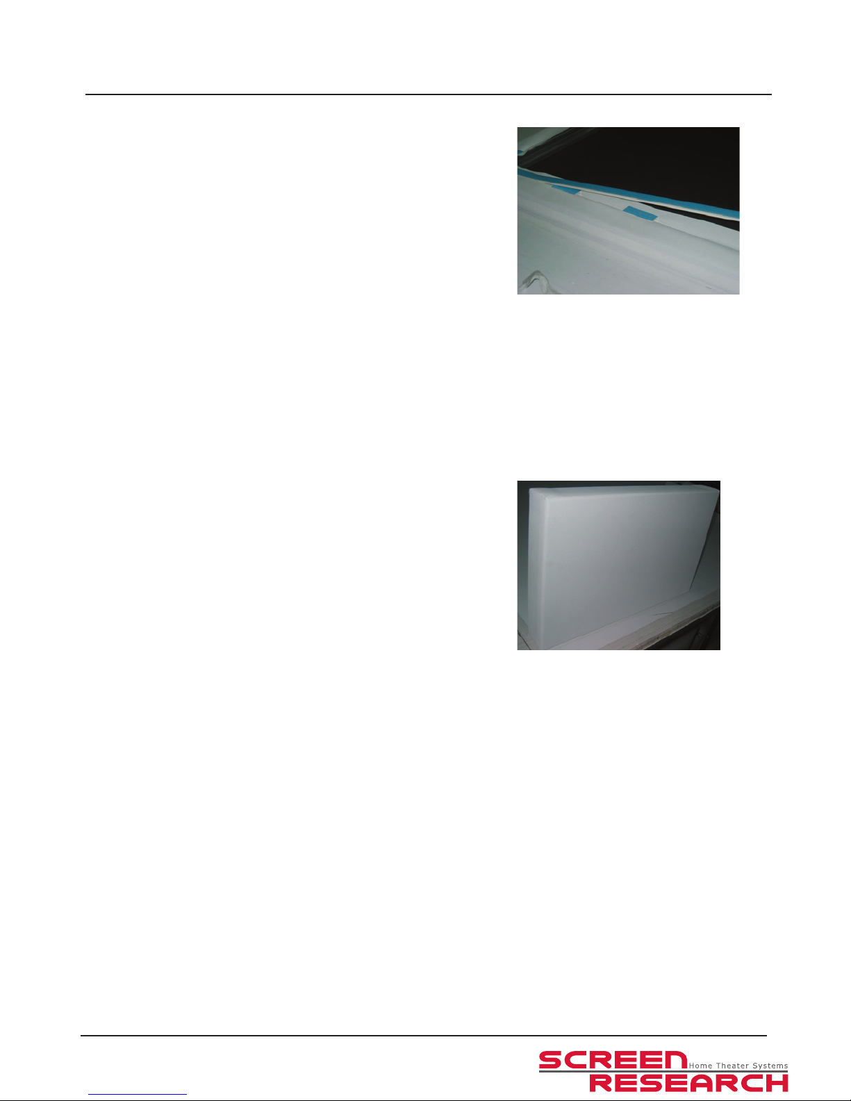
3. Tension the fabric using the long pieces of Pi-Grip.
Begin with the top of the frame.
If your frame is equipped with frame stiffeners, cut
a piece of Pi-Grip to match the distance between the
two frame stiffeners.
Begin at one end of the Pi-Grip and work your way
towards the other end. You should be able to insert
it by hand, but you may use the included mallet if
necessary.
As you insert the Pi-Grip, apply gentle tension on
the fabric along the axis of the Pi-Grip that you are
inserting.
4. Once you have nished clipping the fabric, verify that
the tension is even and sufcient. You may want to
lift the frame and inspect the front side. If necessary,
retension the fabric by removing and reinserting the
Pi-Grip.
Once you are satised with the tension, trim the
excess fabric with the fabric cutting tool. Leave
about 1” ( 25mm) of spare fabric outside of the edge
of the PI-Grip for future potential retensioning.
Please note that the above pictures are concerning a ClearPix2
projection screen fabric. These will soon be replaced with pictures for a SolidPix1 projection screen fabric.
Please note, the way of attaching a SolidPix1 projection
screen fabric is the same way of attaching a ClearPix2
projection screen fabric.
Page 15
SolidPix1™ Integrated Type I Fixed-Frame Screen Installation Manual
15
Revision A 2007.02.22
©Screen Research 2006
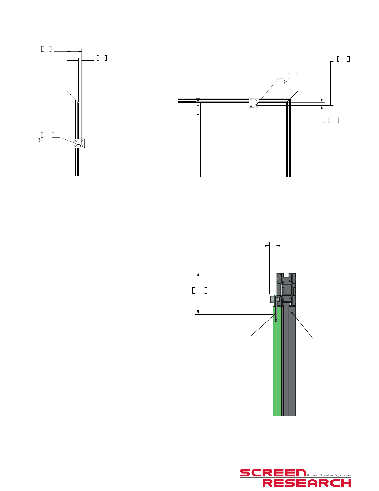
Mounting Dimensions
81mm
3.2"
12mm
0.5"
Mounting
brackets
Frame
There are 4 at wall-mounting brackets. Each has a
tapered notch to be hung on a hanging bolt up to
8mm (5/16”) diameter. The hanging brackets attach
to the frame with square nuts which can slide in any
of the grooves around the frame’s perimeter. The
brackets can be positioned along the top or the sides
of the frame. The brackets stand off 12mm (0.5”) from
the surface of the wall.
17mm
0.7"
81mm
3.2"
8.20mm
0.32"
81mm
3.2"
17mm
0.7"
8.20m
0.3"
Side Mounting Top Mounting
Page 16

SolidPix1™ Integrated Type I Fixed-Frame Screen Installation Manual
Screen Care
Your cinema-quality viewing surface is delicate. Special attention to these instructions should be followed when cleaning.
Cleaning your SolidPix™ Fixed Frame Screen surface
NEVER attempt to use solvents, chemicals or abrasive cleaners on the screen. A soft cloth or brush may be used to lightly whisk
away any loose dirt or particles. Do not use a sharp instrument to remove any
particles. Softly brush from the center to the edges. An upholstery brush attachment on a vacuum cleaner may be used,
but only if it is perfectly clean. We encourage you to keep your screen clean. Avoid getting any foreign materials on it, as
cleaning it may prove very difcult or even impossible (paint, ink, etc.). Never paint in the vicinity of the screen unless the
fabric is completely protected.
Page 17
ADEO SCREEN Sp. Z o.o.
Screen Research
Ul. Boelslawa Krzywoustego 31
59-500 Zlotoryja,
Poland - Europe
Tel. +48 76 850 53 01
Fax + 48 76 850 53 70
North America
Tel. +1 800 510-8850
Fax +1 800 910-8510
Email
To place orders: [email protected]
To get quotations: [email protected]
To contact Technical Support: [email protected]
© Copyright 2013 Adeo Screen. All rights reserved.
Adeo Screen products are covered by one or more of the following patents:
No. 08.02361 (France); No. 09.03989 (France); No. 167.61.72 (Europe); No. 167.75.55 (Europe); No. EP 2277083 (Europe);
No. US 7 777 947-B2 (USA); No. US 7 466 483-B2 (USA); No. US 2011 043908 (USA); USPTO : 200 701 71 522 (USA);
No. 200480025260.9 (China); No. 1126/CHENP/2007 (India); No. 2006-524398 (Japan) pending;
ClearPix, ClearPix 2, ClearPix 3; ClearPix 4k, SilverPix 3D; SilverPix 3D Sonic; MultiPix 4K; MultiPix 4K Sonic; SolidPix, SolidPix Sonic, X-Mask, C-Mask, E-Mask, LeWing,
TheaterCurve, Pi-Grip, E-Grip, StopLight, DécorMask, TailorMade and the Screen Research logo are all trademarks of Adeo Screen.
THX is a trademark of THX Ltd.
ISF is a trademark of Imaging Science Foundation Inc..
Sivoia QED and Sivoia QS are the registered trademarks of Lutron Electronics Co., Inc..
All other trademarks are the property of their respective owners.
 Loading...