

Page 1
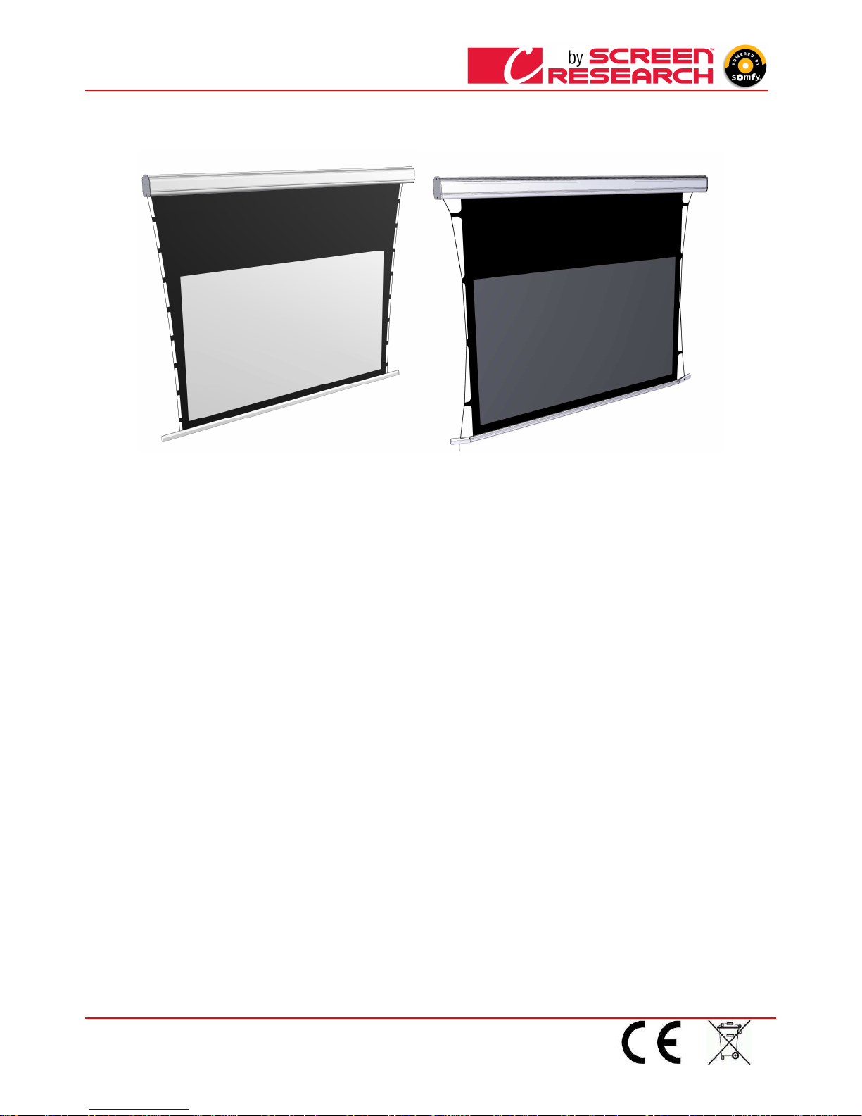
CLCTS-CLCLT Installation Manual
Made by Adeo Screen sp. Z o.o. (Polska)
Specifications are subject to change without notice.
Please verify that you are working with the latest revision of this document before specifying your screen.
Doc: CLCTS-CLCLT – Installation Manual rev5 | 03.02.2015
Download at: www.screenresearch.com 2015 AdeoSreen All Rights Reserved.
Rohs Compliant
Mod. CLCTS
Code PRONCLCTS-XXXXX
Mod. CLCLT
Code PRONCLCLT-XXXXX
Manuale d’installazione e d’uso schermo avvolgibile
Roller screen installation and user manual
Manuel d’installation et utilisateur de l‘écran
Motor Leinwand Montage- und Benutzerhandbuch
Manual de instalación y uso de la pantalla enrollable
Instrukcja obsługi ekranu
Page 2
ITALIANO - Manuale d’uso schermo
Made by Adeo Screen sp.
Z o.o. (Polska) Specifications a
re subject to change without notice. E&OE
Please verify that you are working with the latest revision of this document before specifying your screen.
Doc: Manual CLCTS-CLCLT rev5 | 03.02.2015| Download at: www.screenresearch.com 2015 AdeoSreen All Rights Reserved.
Page
2
01
01 01
01 INTRODUZIONE
INTRODUZIONEINTRODUZIONE
INTRODUZIONE
Il presente manuale è parte integrante del prodotto e la sua lettura e comprensione sono di fondamentale importanza per la sicurezza . In esso sono descritte le norme e le modalità di
impiego che consentiranno al cliente un co rretto e sicuro uso dello schermo. Il manuale deve sempre accompagnare il prodotto e va c ustodito con cura in luogo idoneo a garantirne
l’integrità fisica e facilmente accessibile a c hiunque sia autorizzato alla sua consultazione. Ogni utilizzatore del prodotto è respo nsabile della salvaguardia del manuale. L’utilizzatore è
inoltre responsabile del controllo della funz ionalità dello schermo e della riparazione o sostituzione di parti soggette ad usura che potrebbero causare danni.
Le immagini contenute in questo manu ale hanno lo scopo di descrivere in maniera dettagliata funzioni, caratteristiche o procedure. Tut tavia possono differire per il tipo di modello
rappresentato, questo non comporta modif iche al significato descrittivo dell’immagine.
02
02 02
02 CARATTERISTICHE GENERALI DEL PRODOTTO
CARATTERISTICHE GENERALI DEL PRODOTTOCARATTERISTICHE GENERALI DEL PRODOTTO
CARATTERISTICHE GENERALI DEL PRODOTTO
Lo schermo prodotto è costruito in conform ità con le disposizioni delle seguenti direttive CE: 2006-95-CE LDV Bassa tensione
2004-108-CE EMC Compatibil ità elettromagnetica
1999-05-CE R&TTE Apparecch iature radio e terminali di telecomunicazione
2005-32-CE CONSUMI Eco de sign
2011-65-CE ROHS Sostanze p ericolose
2002-96-CE RAEE Trattamento rifi uti
2001-95-CE SICUREZZA Prodotti s icuri
Lo schermo descritto nel presente manuale deve essere utilizzato solo ed esclusivamente come supporto per la videoproiezione. Quals iasi altro uso non previsto da questo manuale, non è acconsentito.
Lo schermo contiene uno o più tessuti di pr oiezione in PVC plastificato senza cadmio oppure in FIBRA di VETRO impregnata di PVC plastific ato, ogni tessuti può essere classificato di categoria:
- M1 o M2 s econdo la regolament azione Francese (LNE Laboratoire national de métrologie et d’essais – SME Centre de recherches du Bouchet -
WARRINGTONFIRE GENT Laboratoire de
métrologie et d’essais – IFTH Laboratoire a ccreditè )
- B1 o B2 secondo la regolamentazione Tedesca (LNE Laboratoire national de métrologie et d’essais – SME Centr e de recherches du Bouchet -
WARRINGTONFIRE G ENT Laboratoire national d e
métrologie et d’essais)
- UL94HB secondo la regolamentazione deg li Stati Uniti D’America (THE GOVMARK Organization, Inc.)
Poiché non esiste ancora a livello europeo una armonizzazione tra le varie normative nazionali di classificazione si esplicita che la classe M1 francese corrisponde a materiale non infiammabile e
la
classificazione M2 corrisponde a mater iale non facilmente infiammabile.
03
03 03
03 DISIMBALLO DELLO SCHERMO
DISIMBALLO DELLO SCHERMODISIMBALLO DELLO SCHERMO
DISIMBALLO DELLO SCHERMO E MOVIMENTAZIONE PRODOTTO
E MOVIMENTAZIONE PRODOTTOE MOVIMENTAZIONE PRODOTTO
E MOVIMENTAZIONE PRODOTTO
Assicurarsi che nessuna parte de llo schermo sia stata danneggiata durante il trasporto. In caso di anomalia comunica rlo tempestivamente al rivenditore. Verificare che siano presenti tutti gli accessori per
tipo di schermo descritti nel manuale .
Schermo avvolgibile motorizza to o Radio integrato
Schermo avvolgibile motorizza to o Radio integratoSchermo avvolgibile motorizza to o Radio integrato
Schermo avvolgibile motorizza to o Radio integrato
Schermo avvolgibile arganello
Schermo avvolgibile arganelloSchermo avvolgibile arganello
Schermo avvolgibile arganello
-
2 Kit di staffe per l’installazione (per schermi fino alla larghezza di 3mt)
-3 Kit di staffe per l’installazione (pe r schermi oltre alla larghezza di 3mt)
-2 Staffe laterali (per schermi version e senza cassonetto)
-1 commutatore unipolare 10°, 250 V uomo presente con frecce direzionali, compreso di calotta per montaggio a parete
-1 trasmettitore a radio frequenza (p er schermi versione radio integrato)
-1 chiave esagonale in plastica
-1 libretto istruzioni
(non compresi viti e tasselli per paret e)
-
2 Kit di staffe per l’installazione (per schermi fino alla larghezza di 3mt)
-3 Kit di staffe per l’installazione (pe r schermi oltre alla larghezza di 3mt)
-1 asta comando
-1 libretto istruzioni
(non compresi viti e tasselli per paret e)
ATTENZIONE
ATTENZIONEATTENZIONE
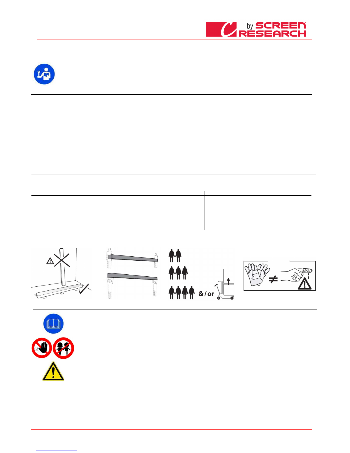
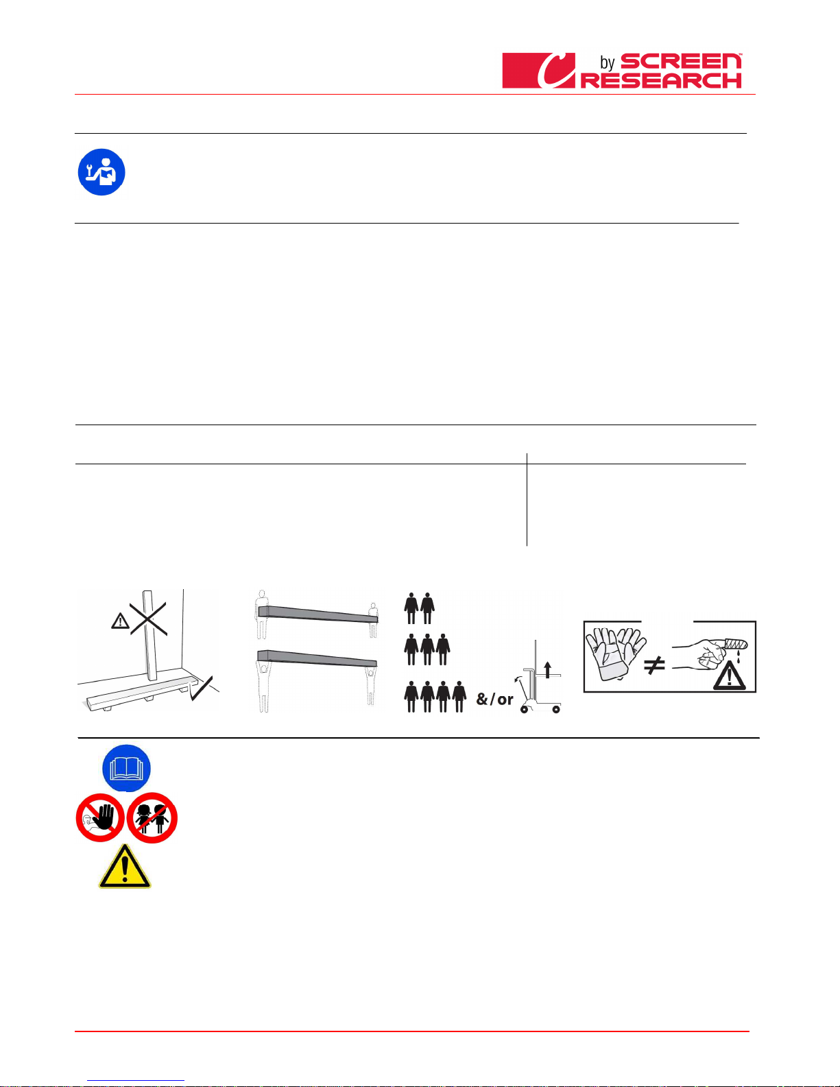
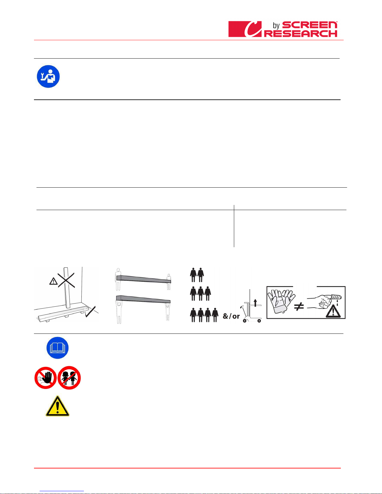
ATTENZIONE non usare taglierini o oggetti appuntiti per aprire l'imballo, utilizzare sempre guanti di protezione durante l’apertura dell’imballo e l’installazione o movimentazione del prodotto. Movimentare
e installare il prodotto minimo in due tre o quattro persone in base al peso del prodotto (valori di riferimento per carico prope rsona: 25kg maschio - 15kg femmina). In caso di pesi superiori si raccomanda
di utilizzare attrezzatura di sollevame nte specifica.
04
04 04
04 NORME GENERALI DI SICUREZZA
NORME GENERALI DI SICUREZZANORME GENERALI DI SICUREZZA
NORME GENERALI DI SICUREZZA
Assicurarsi sempre di av er letto e compreso bene le istruzioni e le avvertenze contenute in questo manuale prima di iniziare ad utilizzare il prodotto e di effettuarne qualsiasi
intervento di manutenzione.
- Divieto assoluto di installare gli schermi sopra zone di possibile transito di persone. Controllare, prima e durante l’utilizzo, che lo schermo non generi situazioni pericolose.
- Non manomettere, togliere o danneggiare nessun elemento o parte dello schermo.
- Non eseguire mai operazioni di manutenzione sullo schermo con motore acceso (Per una maggior sicurezza, togliere l’alimentazione).
- Divieto assoluto di utilizzo del prodotto ai bambini. Divieto assoluto di far avvicinare i bambini allo schermo durante il suo movimento.
Ogni schermo è coperto da garanzia, la cui validità dipende dall’effettivo rispetto ed esecuzione delle istruzioni contenute in questo manuale.
ATTENZIONE:
ATTENZIONE:ATTENZIONE:
ATTENZIONE: I kit di installazione di ogni schermo, non contengono viti e tappi ad espansione per il fissaggio alle pareti/soffitti. L’installatore è responsabile della scelta
adeguata di viti e sistemi di fissaggio, in base alle differenti tipologie di materiale delle pareti o soffitti alle quali deve installare lo schermo.
Un’installazione errata può compromettere la sicurezza delle persone che useranno il prodotto, il produttore non è responsabile per danni a cose o persone causati da
installazione errata, uso improprio dello schermo, scarsa o insufficiente manutenzione.
Il produttore non è responsabile di problemi legati ad errori di installazione. Se necessario contattate il nostro ufficio tecnico per eventuali chiarimenti.
L’installazione dello schermo, i collegamenti elettrici e le verifiche in caso di malfunzionamento degli avvolgimenti motorizzati devono essere effettuati dal rivenditore
autorizzato o da personale competente e a conoscenza dei rischi che può presentare l’energia elettrica. Il cavo di collegamento non può essere sostituito. Se il cavo è
danneggiato lo schermo deve essere sostituito. La manomissione dei fine corsa o la foratura del sigillo posto sopra i fori comporta la decadenza della garanzia.
FINITO IL MONTAGGIO DELLO SCHERMO SULLE STAFFE E’ OBBLIGATORIO VERIFICARE LA PERFETTA ORIZZONTALITA’ PRIMA DELL’UTILIZZO.
Page 3
ITALIANO - Manuale d’uso schermo
Made by Adeo Screen sp.
Z o.o. (Polska) Specifications a
re subject to change without notice. E&OE
Please verify that you are working with the latest revision of this document before specifying your screen.
Doc: Manual CLCTS-CLCLT rev5 | 03.02.2015| Download at: www.screenresearch.com 2015 AdeoSreen All Rights Reserved.
Page
3
05
05 05
05 AVVERTENZE E PRECAUZIONI PER L’UTILIZZO
AVVERTENZE E PRECAUZIONI PER L’UTILIZZOAVVERTENZE E PRECAUZIONI PER L’UTILIZZO
AVVERTENZE E PRECAUZIONI PER L’UTILIZZO
Gli schermi sono indicati per utilizzi in ambienti interni con condizioni di temperatura (20 - 25 °C) ed umidità normali. Particolari precauzioni vanno adottate per utilizzi in
ambienti esterni, soprattutto in riferimento alle condizioni di temperatura e polverosità degli stessi.
Non lasciare esposto per lunghi periodi il telo di proiezione alla luce solare per prevenire l’ingiallimento dello stesso (verificare anche che, a causa dell’ esposizione alla luce
solare, lo schermo non raggiunga i livelli di temperatura sopra indicati).
Poiché il materiale di cui è composto il telo di proiezione (PVC) tende a caricarsi elettrostaticamente, una presenza eccessiva di polveri nell’ ambiente di proiezione può
provocare un degrado delle qualità ottiche del telo a causa della deposizione delle polveri per attrazione elettrostatica (vedi anche pulizia del telo di proiezione).
ATTENZIONE:
ATTENZIONE:ATTENZIONE:
ATTENZIONE: Non forzare manualmente la fuoriuscita del telo perché potrebbe provocare danni al motore o il distacco del cassonetto di contenimento dalle staffe di fissaggio.
Non permettere ai bambini di giocare con i dispositivi di comando fissi. Tenere i telecomandi lontano dai bambini.
Osservare lo schermo in movimento e tenere lontane le persone finché lo schermo non sia completamente chiuso.
E’ v ietato, bloccare, impedire e forzare il movimento dello schermo, aggrapparsi o dondolarsi , aggiungere o applicare qualunque oggetto al telo o fondale, modificare la
struttura dello schermo; in quanto potrebbe causare danni al sistema di avvolgimento con conseguenti danni a cose e persone.
06
06 06
06 PULIZIA MANUTENZIONE
PULIZIA MANUTENZIONEPULIZIA MANUTENZIONE
PULIZIA MANUTENZIONE
Lo schermo e i tessuti d i proiezione degli schermi sono delicati, quindi b isogna prestare particolare attenzione e seguire le segue nti istruzioni per la loro pulizia:
Non utilizzare mai solve nti, prodotti chimici o abrasivi o strumenti appuntiti pe r pulire la superfice.
Evitare qualsiasi contatt o con altri materiali (vernici, inchiostri ect) in quanto p otrebbe essere impossibile rimuoverli dal tessuto.
TESSUTI DI PROIEZIONE CLEARPIX
TESSUTI DI PROIEZIONE CLEARPIXTESSUTI DI PROIEZIONE CLEARPIX
TESSUTI DI PROIEZIONE CLEARPIX: Usare un panno morbido, pulito, inu midito utilizzandolo sempre con movimenti che parto no dal centro dell’area di proiezione verso i lati esterni . E’ acconsentito utilizzare
un spazzola installata su aspirapolvere solo se le setole sono morbide e perfettamente pulite.
TESSUTI DI PROIEZIONE SOLIDPIX, MULTI
TESSUTI DI PROIEZIONE SOLIDPIX, MULTITESSUTI DI PROIEZIONE SOLIDPIX, MULTI
TESSUTI DI PROIEZIONE SOLIDPIX, MULTIPIX,
PIX,PIX,
PIX,: Per pulire telo di p roiezione, utilizzare un panno morbido, pulito, inum idito, eventualmente abbinato con detergenti a base n eutra o alcool. Poiché dopo la
pulizia potrebbe verifica rsi che il telo si carichi di elettricità statica, a causa de llo sfregamento con il panno, si consiglia di passare, co n un panno pulito, un liquido antistatico sul telo per evita re che la
polvere venga nuovame nte attratta dallo stesso
TESSUTI DI PROIEZIONE
TESSUTI DI PROIEZIONE TESSUTI DI PROIEZIONE
TESSUTI DI PROIEZIONE SILVERPIX
SILVERPIX SILVERPIX
SILVERPIX Obbligatorio leg gere attentamente il foglio allegato al tessuto dello sc hermo
PROFILI GENERICI:
PROFILI GENERICI:PROFILI GENERICI:
PROFILI GENERICI: Per pulire il profilo spolverare utilizzando un panno mor bido pulito ed eventualmente dei detergenti non aggress ivi.
PROFILI VELLUTATI
PROFILI VELLUTATIPROFILI V ELLUTATI
PROFILI VELLUTATI: Per pulire il profilo spolverare utilizzando un panno morbido pulito o spazzole co
n sedole morbide e antista tiche. E’ acconsentito utilizzare un spazzola installata s u aspirapolvere solo se le
setole sono morbide e perf ettamente pulite.
STRUTTURA e STAFF E DI FISSAGGIO
STRUTTURA e STAFF E DI FISSAGGIOSTRUTTURA e STAFF E DI FISSAGGIO
STRUTTURA e STAFF E DI FISSAGGIO: E’ obbligatorio verificare periodica mente lo stato del prodotto e la tenuta delle sue staffe di fis saggio. In caso di presenza di deformazioni, lacera zioni o cedimenti
strutturali di staffe viti o componenti del prodotto, è obbligatorio mettere imm ediatamente in sicurezza la zona circostante lo schermo , per evitare qualsiasi tipo di danno a cose e persone. Successivamente è
obbligatorio provvedere all’immediata sosituzione del presunto compon ente difettoso e al ripristino del prodotto.
07
07 07
07 ISTRUZIONI PER L’INSTALLAZIONE
ISTRUZIONI PER L’INSTALLAZIONEISTRUZIONI PER L’INSTALLAZIONE
ISTRUZIONI PER L’INSTALLAZIONE
ATTENZIONE:
ATTENZIONE:ATTENZIONE:
ATTENZIONE: E’ assolutamente vietato installare lo sc hermo su pareti mobili o cavi instabili, le staffe devono essere applicate su superfi ci che garantiscono nel tempo la distanza fra
una staffa e l’altra. L’installazione d ello schermo deve essere effettuato con viti e tasselli adeguati al peso e alla tipologia di p arete o soffitto sulle quali si vuole fissare le staffe, prima
di incominciare l’installazione sceglie te il tipo di tassello o fissaggio seguendo lo schema seguente:
Schermo con larghezza fino a cm
Schermo con larghezza fino a cmSchermo con larghezza fino a cm
Schermo con larghezza fino a cm
160
160160
160
200
200200
200
250
250250
250
300
300300
300
360
360360
360
410
410410
410
520
520520
520
620
620620
620
Peso complessivo da conside rare
Peso complessivo da conside rare Peso complessivo da conside rare
Peso complessivo da conside rare
Kg 20
Kg 20Kg 20
Kg 20
Kg 25
Kg 25Kg 25
Kg 25
Kg 30
Kg 30Kg 30
Kg 30
Kg 35
Kg 35Kg 35
Kg 35
Kg 45
Kg 45Kg 45
Kg 45
Kg 50
Kg 50Kg 50
Kg 50
Kg 100
Kg 100Kg 100
Kg 100
Kg 150
Kg 150Kg 150
Kg 150
IIIINSTALLAZIONE A PARETE:
NSTALLAZIONE A PARETE:NSTALLAZIONE A PARETE:
NSTALLAZIONE A PARETE:
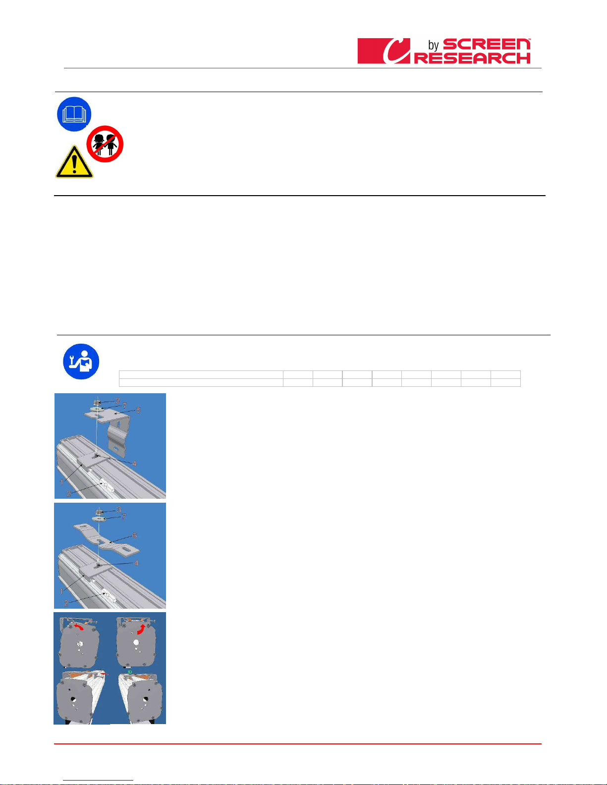
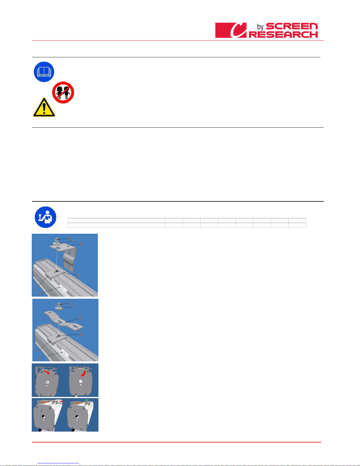
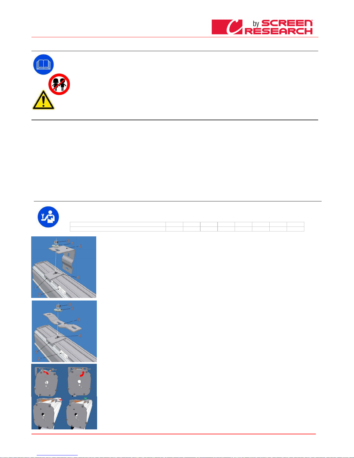
inserire la vite 4 con la filettatura rivo lta verso l’alto nella placca 1 ed avvitare un poco il dado 3 lasciando 4-5 mm di lasco; a gganciare la placca 1 al
cassonetto e inserire lo spinotto in p lastica 2 nello scanso della staffetta. Va sottolineato che, ai fini del solo montaggio, è ind ifferente se si monta la placca
in un verso piuttosto che nell’ altro e ssendo i profili di aggancio del cassonetto perfettamente simmetrici. Fissare a parete la staffa 5 con tasselli a
espansione adeguati al tipo di muro (minimo Ø 8 mm) e fissare la placca 1 con la staffa 5 usando la rondella 7 e il bullone 3.
INSTALLAZIONE A SOFFITTO:
INSTALLAZIONE A SOFFITTO: INSTALLAZIONE A SOFFITTO:
INSTALLAZIONE A SOFFITTO:
fissare le staffe a soffitto 6, fornite d i serie con lo schermo, con tasselli a espansione adeguati al tipo di muro (minimo Ø 8 m m), a circa 10 - 15 cm dalle
estremità del cassonetto. Per gli sche rmi di larghezza superiore ai 350 cm la terza staffa viene posizionata al centro del casso netto. inserire la vite 4 con la
filettatura rivolta verso l’alto nella pla cca 1 ed avvitare un poco il dado 3 lasciando 4-5 mm di lasco; agganciare la placca 1 a l cassonetto e inserire lo
spinotto in plastica 2 nello scanso de lla staffetta. Fissare la placca 1 con la staffa 6 usando la rondella 7 e il bullone 3.
installazione a soffitto direttamente c on le placche di fissaggio:
E’ possibile installare a soffitto dirett amente le placche di aggancio 1 se si desidera che il cassonetto sia il più possibile adere nte al soffitto (attenzione: per
effettuare con facilità e rapidità tale installazione è richiesta una ottima planarità del soffitto in oggetto nonché un perfetto a llineamento delle placche).
Fissare le placche con tasselli a espa nsione deguati al tipo di soffitto (minimo Ø 8 mm), a circa 10 - 15 cm dalle estremità de l cassonetto. Per questo tipo di
montaggio il lato della placca per lo spinotto di fissaggio va, di norma, rivolto verso il lato anteriore del cassonetto per permett ere un facile inserimento dello
spinotto. Verificare in modo accurato l'allineamento e la orizzontalità delle placche. Allo scopo si possono utilizzare deg li spessori tipo le rondelle metalliche
incluse nella confezione. Attenzione c he dalla accuratezza di tale operazione dipende la velocità e la facilità del succ essivo aggancio del cassonetto alla
placca. Per gli schermi di larghezza s uperiore ai 350 cm la terza placca viene posizionata al centro del cassonetto. Inserire il ca ssonetto nelle placche con un
movimento semirotatorio (inseriment o a scatto) ed infilare gli spinotti di plastica che assicurano il fissaggio del cassonetto all e placche.
INSTALLAZIONE CON STAFFE A SISTEMA RAPIDO:
INSTALLAZIONE CON STAFFE A SISTEMA RAPIDO: INSTALLAZIONE CON STAFFE A SISTEMA RAPIDO:
INSTALLAZIONE CON STAFFE A SISTEMA RAPIDO:
1) fissare con tasselli a espansione a deguati (minimo Ø 8 mm) le staffe (è possibile il fissaggio a soffitto o a parete) controllan do il loro livellamento;
2) fissare lo schermo alle staffe segu endo le figure a sinistra
Page 4
ITALIANO - Manuale d’uso schermo
Made by Adeo Screen sp.
Z o.o. (Polska) Specifications a
re subject to change without notice. E&OE
Please verify that you are working with the latest revision of this document before specifying your screen.
Doc: Manual CLCTS-CLCLT rev5 | 03.02.2015| Download at: www.screenresearch.com 2015 AdeoSreen All Rights Reserved.
Page
4
08
08 08
08 REGOLAZIONE CONTRAPESO TENSIONATURA
REGOLAZIONE CONTRAPESO TENSIONATURAREGOLAZIONE CONTRAPESO TENSIONATURA
REGOLAZIONE CONTRAPESO TENSIONATURA (solo per versione TENSIO; no TENSIO CLASSIC )
(solo per versione TENSIO; no TENSIO CLASSIC )(solo per versione TENSIO; no TENSIO CLASSIC )
(solo per versione TENSIO; no TENSIO CLASSIC )
09
09 09
09 IDENTIFICAZIONE TIPO MOTORE
IDENTIFICAZIONE TIPO MOTOREIDENTIFICAZIONE TIPO MOTORE
IDENTIFICAZIONE TIPO MOTORE –––– CARATTERISTICHE
CARATTERISTICHE CARATTERISTICHE
CARATTERISTICHE –––– COLLEGAMENTO ELETTRICO
COLLEGAMENTO ELETTRICOCOLLEGAMENTO ELETTRICO
COLLEGAMENTO ELETTRICO
Il tipo di motore installato sul prodotto è identificato sull’etichetta riportante il logo CE e applicata su ogni prodotto, all’apertura dell’imballo si prega di controllare tale etichetta e di identificare il modello
corretto di motore per effettuare la corretta installazione e il corretto cablaggio. Nel caso in cui la potenza del motore non corrispondesse alla potenza della linea elettrica del luogo di installazione, si prega di
contattare un tecnico elettricista e fornirsi di un corretto trasformatore di corrente e Hz.
COLLEGAMENTO ELETTRICO:
COLLEGAMENTO ELETTRICO:COLLEGAMENTO ELETTRICO:
COLLEGAMENTO ELETTRICO:
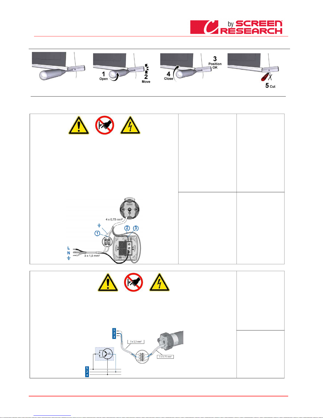
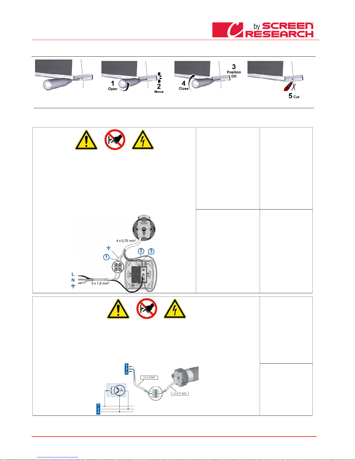
Il cablaggio elettrico deve rispettare le norme CEI in vigore. La norma CEI EN 60335-1 prevede che nella rete di
alimentazione ci sia un dispositivo di disconnessione onnipolare con una distanza di apertura dei contatti di almeno
3 mm. Utilizzare per il comando dello schermo solo il commutatore fornito a corredo, o modello equivalente,
seguendo le indicazioni dello schema di collegamento a sinistra (se il motore è montato sulla sinistra i colori dei fili
vanno invertiti, cioè discesa = marrone, salita = nero). Il commutatore deve essere montato a vista del prodotto ed
ad un altezza compresa fra 1.5 e 1.8 mt di altezza dal pavimento. Per collegare i cavi al pulsante in dotazione,
togliere le placche frontali per accedere ai pulsanti di blocco/sblocco
ATTENZIONE:
ATTENZIONE:ATTENZIONE:
ATTENZIONE:
La corretta esecuzione degli allacciamenti elettrici, a regola d’arte e nel rispetto delle norme vigenti, è importante ai
fini della prevenzione degli infortuni e del buon funzionamento, inalterato nel tempo, dello schermo.
Prima di eseguire qualsiasi operazione su parti elettriche, assicurarsi che non vi sia tensione.
Il motore negli schermi dotati di cassonetto è posto sulla destra dello schermo visto frontalmente (a richiesta è
possibile averlo inserito sulla sinistra). Non collegare mai due o più motori allo stesso commutatore senza un
comando di gruppo, oppure due commutatori allo stesso motore.
Somfy
Somfy Somfy
Somfy 230V 50Hz
230V 50Hz230V 50Hz
230V 50Hz
Cara
CaraCara
Caratteristiche Motore
tteristiche Motoretteristiche Motore
tteristiche Motore
Frequenza: ~Hz50
Potenza: 90W
Coppia: 6Nm
Velocità: 12Rpm
N° cicli massimi: 2
Lunghezza cavo: 2.5m
Resistenza meccanica:
secondo norma EN14202
T° di funzionamento:
da –20 a +55 °C
Connessione per ogni motore:
Connessione per ogni motore:Connessione per ogni motore:
Connessione per ogni motore:
Blu (Comune)
Marrone (Salita)
Nero (Discesa)
Giallo verde (Terra 230V)
Somfy
Somfy Somfy
Somfy 120V 60Hz
120V 60Hz120V 60Hz
120V 60Hz
Caratteristiche Motore
Caratteristiche MotoreCaratteristiche Motore
Caratteristiche Motore
Frequenza: ~Hz60
Potenza: 80W
Coppia: 88in.lb
Velocità: 14r/min
N° cicli massimi: 2
Lunghezza cavo: 2.5m
Resistenza meccanica:
secondo norma EN14202
T° di funzionamento:
da –20 a +55 ° C
Connessione per ogni motore:
Connessione per ogni motore:Connessione per ogni motore:
Connessione per ogni motore:
Bianco(Comune)
Nero (Discesa)
Rosso (Salita)
Giallo verde (Terra 120V)
COLLEGAMENTO ELETTRICO:
COLLEGAMENTO ELETTRICO:COLLEGAMENTO ELETTRICO:
COLLEGAMENTO ELETTRICO:
Il cablaggio elettrico deve rispettare le norme CEI in vigore. La norma CEI EN 60335-1 prevede che nella rete di alimentazione ci sia un dispositivo di disconnessione
onnipolare con una distanza di apertura dei contatti di almeno 3 mm per ogni singolo motore (es. interruttore spina ecc.) In caso di necessità, questo dispositivo
garantisce una veloce e sicura sconnessione dell’alimentazione elettrica.
Utilizzare i cavi per la connessione come descritto nell’immagine.
ATTENZIONE:
ATTENZIONE:ATTENZIONE:
ATTENZIONE:
La corretta esecuzione degli allacciamenti elettrici, a regola d’arte e nel rispetto delle norme vigenti, è importante ai fini della prevenzione degli infortuni e del buon
funzionamento, inalterato nel tempo, dello schermo. Prima di eseguire qualsiasi operazione su parti elettriche, assicurarsi che non vi sia tensione. Il motore negli
schermi dotati di cassonetto è posto sulla destra dello schermo visto frontalmente L’ azionamento avviene tramite radiocomandi forniti di serie.
Somfy RTS
Somfy RTSSomfy RTS
Somfy RTS 230V 50Hz
230V 50Hz230V 50Hz
230V 50Hz
Caratteristiche Motore
Caratteristiche MotoreCaratteristiche Motore
Caratteristiche Motore
Frequenza: ~Hz50
Potenza: 120W
Coppia: 10Nm
Velocità: 17Rpm
N° cicli massimi: 2
Lunghezza cavo: 3m
T° di funzionamento:da –20 a +55
°C
Frequenza: 433.92 MHz
Portata trasmet: 150m
Connessione per ogni motore:
Connessione per ogni motore:Connessione per ogni motore:
Connessione per ogni motore:
Marrone (Fase 230V)
Blu (Linea 230V)
Giallo verde (Terra 230V)
Page 5
ITALIANO - Manuale d’uso schermo
Made by Adeo Screen sp.
Z o.o. (Polska) Specifications a
re subject to change without notice. E&OE
Please verify that you are working with the latest revision of this document before specifying your screen.
Doc: Manual CLCTS-CLCLT rev5 | 03.02.2015| Download at: www.screenresearch.com 2015 AdeoSreen All Rights Reserved.
Page
5
10
10 10
10 REGOLAZIONE FINE CORSA
REGOLAZIONE FINE CORSAREGOLAZIONE FINE CORSA
REGOLAZIONE FINE CORSA
ATTENZIONE LEGGER E PRIMA DI EFFETTUARE LE REGOLAZIONI
ATTENZIONE LEGGER E PRIMA DI EFFETTUARE LE REGOLAZIONIATTENZIONE LEGGER E PRIMA DI EFFETTUARE LE REGOLAZIONI
ATTENZIONE LEGGER E PRIMA DI EFFETTUARE LE REGOLAZIONI
le regolazioni indicate d evono essere eseguite solo da personale autorizzato e specializzato. l’utilizzo non corretto delle proced ure descritte possono causare
danneggiamenti al prod otto, per i quali non sarà riconosciuta la garanzia.
AVVERTENZE
AVVERTENZEAVVERTENZE
AVVERTENZE
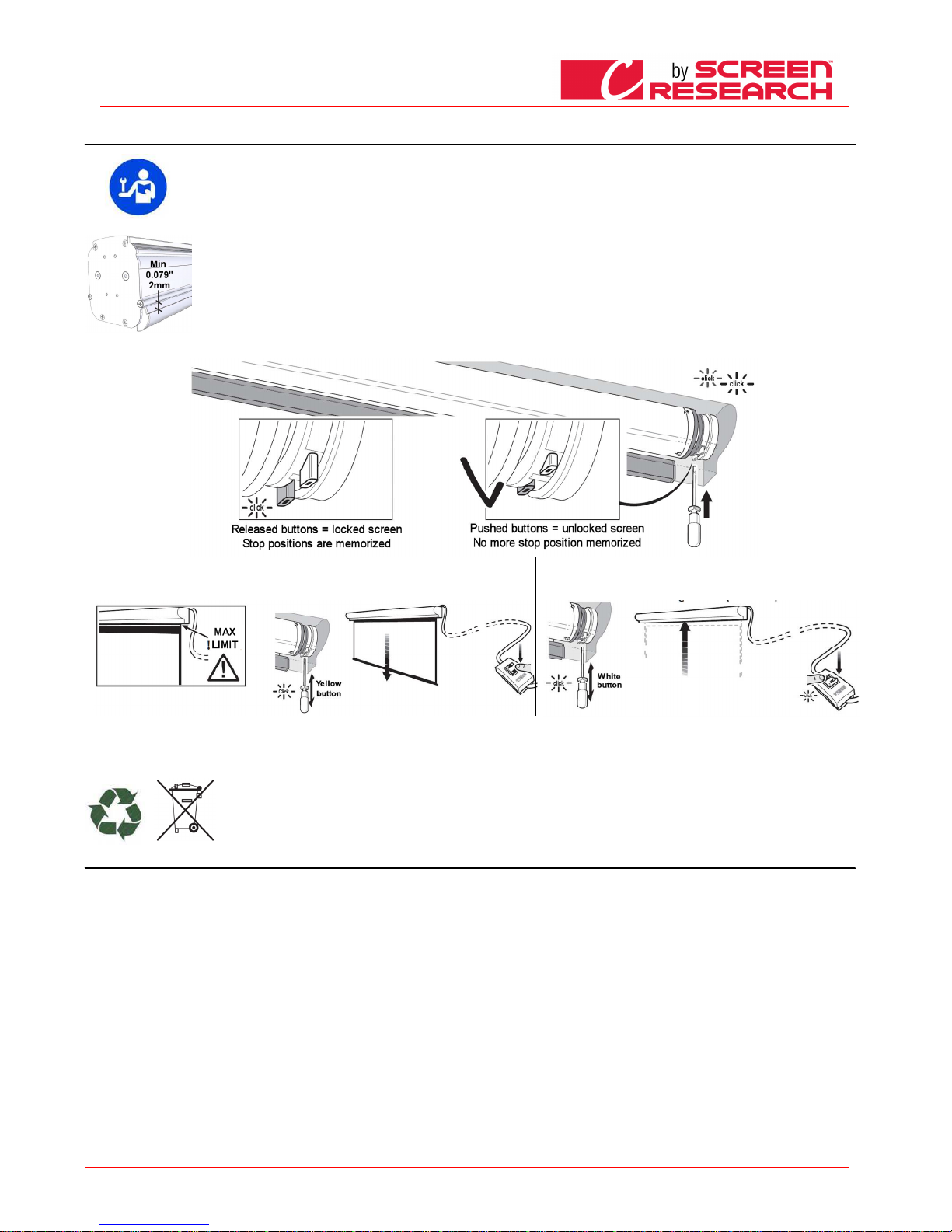
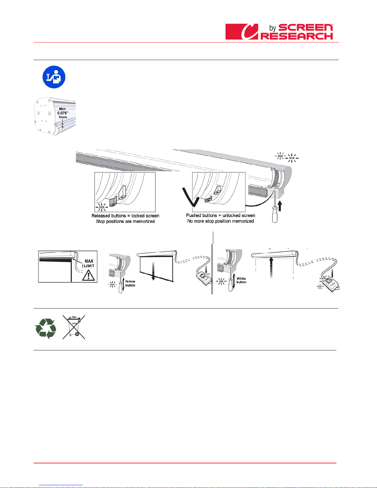
IL FINE CORSA ALTO DEVE ESSERE SEMPRE REGOLATO A 2mm DAL CASSONETTO ” vedi immagine a destra.
Il fine corsa è regolato i n maniera da permettere che il foglio di proiezione sia avv olto per almeno 1,5 giri attorno al rullo per evitare il dista cco del foglio. Particolare
attenzione va posta in c aso di regolazione dei fine corsa per personalizzare l’impo stazione dell’area di visione. Un errata regolazione dei fine corsa può causare:
-Distacco del foglio di p roiezione dal rullo
-Avvolgimento in senso contrario del foglio di proiezione con danneggiamento del la planarità della superficie di proiezione e dei mec canismi di avvolgimento.
-Rottura della saldatura del bordo nero in basso (schermi bordati).
-Sforzo eccessivo sul mo tore con possibile danneggiamento e attivazione della resistenza termica contenuto in esso.
-Avvolgimento eccessivo del sistema di taratura fine corsa con conseguente rottur a della parte meccanica.
GARANZIA
GARANZIAGARANZIA
GARANZIA
Si ricorda agli operatori che in caso di manomissione dei sigilli e danneggiamento derivante da una regolazione errata, gli interventi per ripa razione verranno considerati fuori
garanzia.
-Premere i pulsanti bianc o e giallo per sbloccare la memorizzazione dei fine corsa
-Muovere il telo di proiezione nella posizione di fine corsa basso desiderato, facendo attenzione a non superare
il limite indicato nelle tela di proiezione poi rilasciare il pulsante giallo
-Muovere il telo di proiezione nella posizione di fine corsa alto desiderato, poi
rilasciare il pulsante bianco
SMALTIMENTO DEL PRODOTTO
SMALTIMENTO DEL PRODOTTOSMALTIMENTO DEL PRODOTTO
SMALTIMENTO DEL PRODOTTO
Come per le operazioni d'installazione, anche al termine della vita di questo prodotto, le operazioni di smantellamento devono essere e seguite da personale qualificato.
Questo prodotto è costituito da vari tipi di materiali: alcuni possono essere riciclati, altri devono essere smaltiti. Informatevi sui sistemi di riciclaggio o smaltimento
previsti dai regolamenti vigenti nel vost ro territorio, per questa categoria di prodotto.
Come indicato dal simbolo a fianco è v ietato gettare questo prodotto nei rifiuti domestici. Eseguire quindi la "raccolta separata" per l o smaltimento, secondo i metodi
previsti dai regolamenti vigenti nel vost ro territorio, oppure riconsegnare il prodotto al venditore nel momento dell'acquisto di un nuov o prodotto equivalente.
Attenzione: i regolamenti locali possono pre vedere pesanti sanzioni in caso di smaltimento abusivo di questo prodotto.
GARANZIA
GARANZIAGARANZIA
GARANZIA
1.GARANZIA
1.GARANZIA 1.GARANZIA
1.GARANZIA ScreenResearch garantisce che il prodotto da essa prodotto sarà esente da difetti di fabbricazione nei materiali e nelle lavorazioni, nel rispetto dei termini e condizioni qui sotto indicati. I tessuti
di proiezione e profili sono garantiti per un periodo di cinque (5) anni dalla data della fattura originale. Motori, comandi motore, telecomandi, e hardware di montaggio sono garantiti per tre (3) anni dalla data
della fattura originale.
2.CONDIZIONI E LIMITAZIONI
2.CONDIZIONI E LIMITAZIONI 2.CONDIZIONI E LIMITAZIONI
2.CONDIZIONI E LIMITAZIONI La presente Garanzia è soggetta alle seguenti condizioni e limitazioni. La garanzia è nulla e inapplicabile se il prodotto è stato usato o manipolato non in conformità con il
manuale di istruzione contenuto nella confezione del prodotto, se abusato o utilizzato impropriamente, se danneggiato da un incidente o negligenza durante il trasporto, o se il difetto è dovuto a riparazioni o
manomissioni effettuate da personale non autorizzato. Il prodotto deve essere installato da un professionista debitamente autorizzato da ScreenResearch e devono essere eseguite regolarmente le
manutenzioni indicate nel manuale.
3.RESI
3.RESI 3.RESI
3.RESI Nessun prodotto restituito sarà accettato senza autorizzazione scritta (RMA) da parte ScreenResearch. Il prodotto deve essere reso, imballato nella confezione originale o equivalente, al fine di evitare
danni durante il trasporto. Il prodotto deve essere imballato e restituito a ScreenResearch o un centro riparazione autorizzato, a carico del cliente. Le spese di riconsegna del prodotto sono a carico di
ScreenResearch. Il prodotto restituito deve essere accompagnato da una descrizione scritta del difetto e una fotocopia della ricevuta originale di acquisto. Questa ricevuta deve indicare chiaramente il
modello e numero di serie, la data di acquisto, il nome e l'indirizzo dell'acquirente e rivenditore autorizzato e il prezzo pagato dall'acquirente. ScreenResearch si riserva il diritto di modificare il design di
qualsiasi prodotto, senza obblighi nei confronti di prodotti fabbricati in precedenza e di modificare i prezzi o le specifiche di qualsiasi prodotto senza preavviso o obbligo nei confronti di qualsiasi persona.
4.RIMEDI
4.RIMEDI 4.RIMEDI
4.RIMEDI Nel caso in cui il prodotto non sia conforme alla garanzia sopra, l'unico rimedio per l'acquirente ai sensi della presente Garanzia Limitata è quello di restituire il prodotto a ScreenResearch o a un
Centro di assistenza autorizzato. La non conformità sarà rettificata senza spese di manodopera o per componenti.
5.LIMITE PER ACQUIRENTE ORIGINALE
5.LIMITE PER ACQUIRENTE ORIGINALE 5.LIMITE PER ACQUIRENTE ORIGINALE
5.LIMITE PER ACQUIRENTE ORIGINALE Questa garanzia è ad esclusivo beneficio dell'acquirente originale del prodotto coperto e non deve essere trasferito ad un successivo acquirente del prodotto.
6.VARIE
6.VARIE 6.VARIE
6.VARIE Tutte le garanzie implicite relative a prodotti di ScreenResearch sono limitate alla durata di questa garanzia. La garanzia non si estende a eventuali da
nni diretti o indiretti per l'acquirente. Alcuni stati
o paesi non consentono limitazioni sulla durata di una garanzia implicita o l'esclusione o la limitazione di danni incidentali o consequenziali, pertanto le suddette limitazioni o esclusioni potrebbero non
essere applicabili. Questa garanzia conferisce diritti legali specifici, e si può anche avere altri diritti che variano da stato a stato, o da paese a paese.
7.RICHIESTE
7.RICHIESTE7.RICHIESTE
7.RICHIESTE per quanto riguarda la garanzia limitata di cui sopra, possono essere inviate al rivenditore autorizzato di ScreenResearch.
8. SUPPORTO DI GARANZIA GESTITO DA DISTRIBUTORI AUTORIZZATI
8. SUPPORTO DI GARANZIA GESTITO DA DISTRIBUTORI AUTORIZZATI 8. SUPPORTO DI GARANZIA GESTITO DA DISTRIBUTORI AUTORIZZATI
8. SUPPORTO DI GARANZIA GESTITO DA DISTRIBUTORI AUTORIZZATI Screen Research ha autorizzato la distribuzione dei loro prodotti in molti paesi del mondo. In ogni paese, il Distributore autorizzato
importatore è responsabile per l'assistenza in garanzia dei prodotti venduti nei rispettivi paesi. Il servizio di garanzia deve essere ottenuto dal rivenditore importatore o il distributore da cui si ha acquistato il
prodotto.
Page 6
ENGLISH - Screen user manual
Made by Adeo Screen sp.
Z o.o. (Polska) Specifications a
re subject to change without notice. E&OE
Please verify that you are working with the latest revision of this document before specifying your screen.
Doc: Manual CLCTS-CLCLT rev5 | 03.02.2015| Download at: www.screenresearch.com 2015 AdeoSreen All Rights Reserved.
Page
6
01 INTRODUCTION
01 INTRODUCTION01 INTRODUCTION
01 INTRODUCTION
This manual is an integral part of the product and must be read and understood in all its parts for safety reasons. It contains norms and directions for correct and safe use of the screen.
The manual should never be separated from the product; it must be stored in a suitable place to ensure its integrity, and in such a way as to be easily consulted by authorised personnel.
Product user shall be responsible for the manual’s safekeeping. User shall also be responsible for checking the screen’s functionality and for the repair or replacement of any damaged
parts that could pose a hazard.
Images contained in this manual are intended to provide a detailed description of the product’s functions, characteristics and procedures. Any slight difference, depending on the model
represented, will not change the meaning that the images convey.
02
02 02
02 GENERAL CHARACTERISTICS OF TH E PRODUCT
GENERAL CHARACTERISTICS OF THE PRODUCTGENERAL CHARACTERISTICS OF THE PRODUCT
GENERAL CHARACTERISTICS OF THE PRODUCT
The screen product is manufactured in compliance with the provision s of the following EC directives 2006-95-CE LDV
2004-108-CE EMC
1999-05-CE R&TTE
2005-32-CE Eco design
2011-65-CE ROHS
2002-96-CE RAEEi
2001-95-CE SAFETY
The screen described in this manual must be used exclusively as a support for video projection. Any other use not covered by this manual, it is not consented.
The screen contains one or more Fabric of projection. The Fabric of projection is a cad mium-free plastic p vc sheet or Glass wire (conti nuos filament) plastif ied PVC impregnated, any fabric
can be classified in
category:
- M1 and M2 fire classification under Frenc h standards (LNE Laboratoire national de métro logie et d’essais – SME Centre de recherches du Bouchet -
WA RRINGTONFIRE GENT Laboratoire de
métrologie et d’essais – IFTH Laboratoire accreditè
- B1 and B2 fire c lassification under German standards (LNE Laboratoire n ational de métrologie et d’essais – SME Ce ntre de recherches du Bouchet - WAR
RINGTONFIRE GENT L aboratoire
national de métrologie et d’essais)
- UL94HB fire classification under USA standards (THE GOVMARK Organization, Inc.)
In the absence of a standardisation at a European level of the various national classification norms, it shoul
d be noted that the French M 1 class corresponds to non flammable material and that M2 class
corresponds to flame retardant material.
03
03 03
03 UNPACKING AND HANDING THE SCREEN
UNPACKING AND HANDING THE SCREENUNPACKING AND HANDING THE SCREEN
UNPACKING AND HANDING THE SCREEN
Ensure that the screen has suffered no damage during transport. Should any fault be detected, prompt ly notify your dealer. Verify that all screen accessories have been included
Motorised or integrated radio roller scre
Motorised or integrated radio roller screMotorised or integrated radio roller scre
Motorised or integrated radio roller scre
en
en en
en
Hand winch roller screen
Hand winch roller screenHand winch roller screen
Hand winch roller screen
-
2 Kits of installation brackets (for screens up to 3 m wide)
-3 Kits of installation brackets (for screen over 3 m wide)
-2 lateral brackets (for screen models without case)
-1 10° unipolar, 250V dead man’s selector switch with directional arrows, inclusive of wall mount hood
-1 RF transmitter (for integrated radio screen models)
-1 plastic hex wrench
-1 instructions booklet
(screws and plugs for wall mount are not included)
-
2 Kits of installation brackets (for screen
s up to 3 m wide)
-3 Kits of installation brackets (for screen over 3 m wide)
-1 winch pole
-1 instruction booklet
(screws and plugs for wall mount are not included)
CAUTION
CAUTIONCAUTION
CAUTION do not use cutters or sharp objects to open the wrapping, always use protection gloves when unpacking, handling and installing the product. Depending on the product’s weight (reference load: 25
Kg male – 15 Kg female), handling and installing operations should be performed by two, three or four people a t least. For heavier loads we recommend the use of specific lifting equipment.
04
04 04
04 GENERAL SAFETY NORMS
GENERAL SAFETY NORMSGENERAL SAFETY NORMS
GENERAL SAFETY NORMS
Always read the instructions and warnings set out in this manual very carefully before using the product or before performing any maintenance interventions.
Installation of the screen above passageway is strictly forbidden.. Before and during use, check that the screen poses no risk of hazard.
Do not tamper with, remove or damage any part or component of the screen.
Never perform screen maintenance operations when the motor is on (for maximum safety, remove power supply).
Not children safe. It is mandatory to keep children away during operations with the screen.
All our screens are covered by guarantee; validity of the same shall be subject to user’s full compliance with the instructions contained in this manual.
WARNING:
WARNING:WARNING:
WARNING: Faulty installation may compromise the safety of the product’s operators; manufacturer shall not be held liable for damages to persons or things resulting from faulty
installation, improper use, insufficient or inadequate maintenance of the screen.
Manufacturer shall not be held responsible for problems associated with installation errors.
Screen installation, electrical connections and verifications in case of malfunction of motorised rolling screens must be performed by authorised vendor or by personnel that is
informed and trained in electrical hazards. The connection cable cannot be replaced. If the cable is damaged the screen must be replaced. Tampering with end stops or piercing
the seal placed over holes shall entail the forfeiture of the guarantee. For any necessary clarifications please contact our technical office.
N.B.ONCE THE SCREEN HAS BEEN MOUNTED ON THE BRACKETS, AND PRIOR TO USING IT, USER IS MANDATORILY REQUIRED TO ENSURE THAT THE SCREEN’S POSITION IS
PERFECTLY HORIZONTAL.
Page 7
ENGLISH - Screen user manual
Made by Adeo Screen sp.
Z o.o. (Polska) Specifications a
re subject to change without notice. E&OE
Please verify that you are working with the latest revision of this document before specifying your screen.
Doc: Manual CLCTS-CLCLT rev5 | 03.02.2015| Download at: www.screenresearch.com 2015 AdeoSreen All Rights Reserved.
Page
7
05
05 05
05 WARNINGS AND RECOMMENDATIONS FOR CORRECT USE
WARNINGS AND RECOMMENDATIONS FOR CORRECT USE WARNINGS AND RECOMMENDATIONS FOR CORRECT USE
WARNINGS AND RECOMMENDATIONS FOR CORRECT USE
Our screens are suitable for indoor use at normal temperature (20 - 25 °C) and humidity conditions. Special precautions are necessary for outdoor use, especially as regards
temperature levels and the presence of dust. Exposure to temperatures of over 50 °C can cause permanent deformation of the screen’s flatness, or the screen to come away
from the roller.
Avoid prolonged exposure of the projection screen to solar light to prevent yellowing of the same (ensure that exposure to solar light does not cause the screen to reach said
temperature level).
Since electrostatic charge tends to accumulate on the projection screen (which is made of PVC), attracting dust, excessive dustiness in the projection environment can
deteriorate the optical quality of the screen (see projection screen cleaning instructions).
WARNING: Do not manually force the screen’s unrolling: this could result in the motor being damaged or the screen’s case to come away from the wall mount brackets.
Do not allow children to play with the screen’s control panel. Keep remote control out of children’s reach.
Monitor screen movement and allow no-one near it until it is completely closed.
The following operations: blocking, preventing or forcing the screen’s movement, hanging or swinging from it, adding or applying any object to the screen or backdrop,
modifying the screen’s structure – are strictly forbidden and could result in damages to the screen’s rolling system and ensuing hazard to persons and things.
06
06 06
06 CLEANING AND MAINTENANCE
CLEANING AND MAINTENANCECLEANING AND MAINTENANCE
CLEANING AND MAINTENANCE
Screens and their projec tion surfaces are delicate and must be cleaned with g reat care, according to the following instructions:
Never use solvents, chem ical or abrasive products, or pointed tools to clean th e surface.
Avoid contact with othe r materials (varnishes, inks etc) as they might be impo ssible to remove from the canvas.
FABRIC
FABRICFABRIC
FABRIC CLEARPIX
CLEARPIXCLEARPIX
CLEARPIX: Use a soft, c lean, dampened cloth, wiping from the center of the p rojection surface towards the outer edges. A vacu um-cleaner brush may be used, provided its bristles are soft a nd
perfectly clean.
FABRIC
FABRICFABRIC
FABRIC SOLIDPIX, MULT IPIX,
SOLIDPIX, MULTIPIX,SO LIDPIX, MULTIPIX,
SOLIDPIX, MULTIPIX,: Remove dust from the case wi th a soft, clean cloth and a non aggressive detergent a s necessary.
Clean the projection scr een with a soft, clean, damp cloth, and a neutral or al cohol-base detergent as necessary. Since rubbing the sc reen with a cloth during cleaning operations can cause electrostatic
charge to accumulate, we r ecommend the subsequent application of an antis tatic liquid with a clean cloth, to avoid dust being attract ed again
FABRIC SILVERPIX
FABRIC SILVERPIX FABRIC SILVERPIX
FABRIC SILVERPIX i s Mandatory to read the instructions accompanying the fabric screen
GENERIC
GENERIC GENER IC
GENERIC PROFIL
PROFILPROFIL
PROFILEEEE:::: Remove dust from the case with a soft, clean cloth and a non aggressive detergent as necessary
VELVET PROFILE
VELVET PROFILEVELVET PROFILE
VELVET PROFILE: Clean profile with a soft clean cloth, or a brush with so ft, antistatic bristles. A vacuum-cleaner brush may be used, provided its bristles are soft and perfectly clean .
STRUCTURE and AN CHORING BRACKETS:
STRUCTURE and AN CHORING BRACKETS:STRUCTURE and ANCHORING BRA CKETS:
STRUCTURE and AN CHORING BRACKETS: The state of the product and the anchoring capacity of its brackets must be checke d regularly. In case of canvas deformation or rips, or lo osening of structural
components such as bra ckets or screws, action must be taken immediately to clear the area around the screen and avoid hazard to pe ople and things, replace the defective component and restore the
product's functionality.
07
07 07
07 INSTALLATION INSTRUCTIONS
INSTALLATION INSTRUCTIONSINSTALLATION INSTRUCTIONS
INSTALLATION INSTRUCTIONS
WARNING:
WARNING:WARN ING:
WARNING: It 's absolutely forbidden to install the screen on mobile walls or unstable cables,the brackets must be applied on surfaces that ensure in the time your distance. When
installing the screen use plugs and scr ews suitable for the screen’s weight and for the type of wall or ceiling on which the mount brackets a re to be fixed, based on the following criteria
Screen width up to cm
Screen width up to cmScreen width up to cm
Screen width up to cm
160
160160
160
200
200200
200
250
250250
250
300
300300
300
360
360360
360
410
410410
410
520
520520
520
620
620620
620
Overall weight
Overall weightOverall weight
Overall weight
Kg 20
Kg 20Kg 20
Kg 20
Kg 25
Kg 25Kg 25
Kg 25
Kg 30
Kg 30Kg 30
Kg 30
Kg 35
Kg 35Kg 35
Kg 35
Kg 45
Kg 45Kg 45
Kg 45
Kg 50
Kg 50Kg 50
Kg 50
Kg
Kg Kg
Kg
100
100100
100
Kg 150
Kg 150Kg 150
Kg 150
WALL INSTALLATION:
WALL INSTALLATION:WALL INSTALLATION:
WALL INSTALLATION:
Insert screw 4 with thread turned upwards into plate 1 and screw on nut 3 loosely, leaving a 4-5 mm play; hook plate 1 to the case and ins ert plastic pin 2 into
the slot of the small bracket. Please note t hat, for assembly purpose, the plate can be mounted either way since the hookable sections of the case are perfectly
symmetrical. Secure bracket 5 to the wall with adequate wall type expansion plugs (min. Ø 8 mm) and secure plate 1 to bracket 5 using washer 7 and bolt 3.
CEILING INSTALLATION:
CEILING INSTALLATION: CE ILING INSTALLATION:
CEILING INSTALLATION:
secure ceiling brackets 6 (provided) wi th adequate wall expansion plugs (min. Ø 8 mm), at approx. 10 - 15 cm from the ends of the case. For screens wider
than 350 cm, the third bracket must be p ositioned in the middle of the case. Insert screw 4 with thread turned upwards into plate 1 and s crew on nut 3
loosely, leaving a 4.5 mm play; hook p late 1 to the case and insert plastic pin 2 into the slot of the small bracket. Secure plate 1 to bracket 6 using washer 7
and bolt 3.
Direct ceiling installation with mount p lates:
For closer adherence of the case to the ce iling it is possible to fix mount plates 1 directly to the ceiling (N.B.: for quick and easy performanc e of this operation,
excellent ceiling flatness and perfect a lignment of the plates are required). Secure the plates with expansion plugs suitable for the type of c eiling (min. Ø 8
mm), at approx. 10 - 15 cm from the end s of the case. For this type of installation, as a rule, the side of the plate in which the pin is to be s lotted should be
turned towards the front of the case, to fa cilitate the insertion of the pin. Carefully check the alignment and horizontality of the plates. Metal washers of the
type included in the packaging may be used for the purpose as necessary. Note that an accurate performance of this operation will ens ure ease and speed
when subsequently hooking the case to the plates. For screens wider than 350 cm the third palte must be positioned in the middle of the c ase. Hook the case
to the plates with a semicircular movemen t (until it clicks into position); secure the case to the plates by inserting the plastic pins
QUICK BRACKET VERSION INTALLA TION
QUICK BRACKET VERSION INTALLA TIONQUICK BRACKET VERSION INTALLA TION
QUICK BRACKET VERSION INTALLA TION:
: :
:
1)secure brackets with adequate expansio n plugs (min. Ø 8 mm); ceiling or wall mount are possible; check they are level;
2) fasten screen to brackets as the lef t pictures
Page 8
ENGLISH - Screen user manual
Made by Adeo Screen sp.
Z o.o. (Polska) Specifications a
re subject to change without notice. E&OE
Please verify that you are working with the latest revision of this document before specifying your screen.
Doc: Manual CLCTS-CLCLT rev5 | 03.02.2015| Download at: www.screenresearch.com 2015 AdeoSreen All Rights Reserved.
Page
8
08
08 08
08 COUNTERWEIGHT TENSIONING ADJUSTAMENT
COUNTERWEIGHT TENSIONING ADJUSTAMENTCOUNTERWEIGHT TENSIONING ADJUSTAMENT
COUNTERWEIGHT TENSIONING ADJUSTAMENT
09
09 09
09 MOTOR TYPE IDENTIFICATION
MOTOR TYPE IDENTIFICATION MOTOR TYPE IDENTIFICATION
MOTOR TYPE IDENTIFICATION ––––CHARACTERISTICS
CHARACTERISTICS CHARACTERISTICS
CHARACTERISTICS –––– ELECTRICAL CONNECTION
ELECTRICAL CONNECTIONELECTRICAL CONNECTION
ELECTRICAL CONNECTION
The type of motor installed on the product is identified by a label applied on each product showing the CE logo. When unwrapping the product please check the model type indicated on the label in order to
perform the installation and cable connections correctly. Should the power of the motor be different from that of the supply network of the installation place, please contact an electrician to have a current and
Hz transformer installed.
ELECTRICAL CONNECTION:
ELECTRICAL CONNECTION:ELECTRICAL CONNECTION:
ELECTRICAL CONNECTION:
electric cabling must be conformant with applicable IEC standards. IEC norm EN 60335-1 requires that supply
network be fitted with an omnipolar selector switch with contact opening distance of at least 3 mm. For the screen’s
control use only the selector switch provided by manufacturer, or equivalent model, and follow the instructions of the
connection diagram shown on left (if the motor is mounted on the left, the colours of the wires must be inverted, i.e.
descending = brown, ascending = black). The selector switch must be mounted within sight distance of the product,
at a 1.5 - 1.8 m height from the floor. To connect the wires to the supplied switch, remove the plastic front plates to
access the lock/unlock buttons
WARNI
WARNIWARNI
WARNING:
NG:NG:
NG:
Correctly performed, state-of-the-art, norm-compliant electrical connections are important to prevent accidents and
to ensure the screen’s optimal and unaltered performance over time. Prior to carrying out any operation on electrical
parts ensure that power supply is disconnected. In screens fitted with cases the motor is positioned on the right-hand
side of the screen as seen from the front (upon request it can be located on the left). Never connect two or more
motors to the same selector switch without a control unit or two switches to the same motor..
230V 50Hz
230V 50Hz230V 50Hz
230V 50Hz
Motor characteristics:
Motor characteristics:Motor characteristics:
Motor characteristics:
Frequency: ~Hz50
Power: 90W
Torque: 6Nm
Speed: 12Rpm
Max no. of cycles: 2
Cable length: 2.5m
Mechanical strength:
EN14202 conformant
Operating T°:
from –20 to +55 °C
Connection for each motor:
Connection for each motor:Connection for each motor:
Connection for each motor:
Blue (Common)
Brown (Up)
Black (Down)
Yellow Green (Ground 230V)
120V 60Hz
120V 60Hz120V 60Hz
120V 60Hz
Motor characteristics:
Motor characteristics:Motor characteristics:
Motor characteristics:
Frequency: ~Hz60
Power: 80W
Torque: 88in.lb
Speed: 14r/min
Max no. of cycles: 2
Cable length: 2.5 m
Mechanical strength:
EN14202 conformant
Operating T°:
from –20 to +55 °C
Connection for each motor:
Connection for each motor:Connection for each motor:
Connection for each motor:
White(Common)
Black (Down)
Red (Up)
Giallo verde (Terra 120V)
ELECTRICAL CONNECTION:
ELECTRICAL CONNECTION: ELECTRICAL CONNECTION:
ELECTRICAL CONNECTION:
electric cabling must be conformant with applicable IEC standards. IEC norm EN 60335-1 requires that supply network be fitted with an omnipolar selector switch
with contact opening distance of at least 3 mm. For each motor (e.g. plug switch etc.). In case of need, this device ensures that the power supply is safely and quickly
cut off. Use the wires as described in the figure.
WARNING:
WARNING:WARNING:
WARNING:
Correctly performed, state-of-the-art, norm-compliant electrical connections are important to prevent accidents and to ensure the screen’s optimal and unaltered
performance over time. Prior to carrying out any operation on electrical parts ensure that power supply is disconnected.
Bus cables (black white orange) must be insulated if not used for the push-button command.
In screens fitted with cases the motor is positioned on the right-hand side of the screen as seen from the front.
Operates with standard radio control (supplied).
Somfy RTS
Somfy RTSSomfy RTS
Somfy RTS 230V 50Hz
230V 50Hz230V 50Hz
230V 50Hz
Technical characteristics:
Technical characteristics:Technical characteristics:
Technical characteristics:
Frequency: ~Hz50
Power: 120W
Torque: 10Nm
Speed: 17Rpm
Max no. of cycles: 2
Cable length: 3m
Operating T°:
from –20 to +55 °C
Frequency: 433.92 MHz
Trans. range: 150m
Connection for each motor:
Connection for each motor:Connection for each motor:
Connection for each motor:
Brown (Phase 230V)
Blue (Neutral 230V)
Yellow Green (Ground 230V)
Page 9
ENGLISH - Screen user manual
Made by Adeo Screen sp.
Z o.o. (Polska) Specifications a
re subject to change without notice. E&OE
Please verify that you are working with the latest revision of this document before specifying your screen.
Doc: Manual CLCTS-CLCLT rev5 | 03.02.2015| Download at: www.screenresearch.com 2015 AdeoSreen All Rights Reserved.
Page
9
10
10 10
10 END STOP MOTOR ADJUSTMENT
END STOP MOTOR ADJUSTMENTEND STOP MOTOR ADJUSTMENT
END STOP MOTOR ADJUSTMENT
WARNING
WARNING WARNING
WARNING ---- READ CAREFULL Y BEFORE PERFORMING ADJUSTMENTS
READ CAREFULLY BEFO RE PERFORMING ADJUSTMENTSREAD CAREFULLY BEFO RE PERFORMING ADJUSTMENTS
READ CAREFULLY BEFO RE PERFORMING ADJUSTMENTS
Adjustments shown mus t be performed by authorised and specialised personnel o nly. Incorrect performance of the procedures des cribed may result in damages to the
product which will not b e covered by guarantee.
WARNING
WARNINGWARNING
WARNING
UPPER END STOP MUST AL WAYS BE ADJUSTED AT 2mm FROM THE CASE” see pi cture on the right.
End stop is adjusted so as to allow the projection sheet to wind around the roller at least 1.5 times to avoid the sheet coming loose. Speci al attention must be paid when end
stops are adjusted in su ch a way that projection sheet unwinds beyond the factor y setting. Incorrect adjustment of end stops can cause :
-Projection sheet comin g away from the roller
-Projection sheet windin g the wrong way, with ensuing damage to flatness of the p rojection surface and to winding mechanisms
-Breaking of bottom en d black frame welding (framed screens)
-Excessive strain on mo tor with possible ensuing damage and activation of motor’ s thermal resistance
-Excessive winding of th e end stop adjustment system with ensuing breaking of th e mechanical part
WARRANTY
WARRANTYWARRANTY
WARRANTY
Operators are reminded that in cases where seals have been tampered with and w here any damages have resulted from incorrect adjus tment, repair interventions shall not be
covered by guarantee.
-
-Pushed the White and Yellow buttons for unlocked the end-stop positions.
--Move the projection fabric in the down end position, ATTENTION do not to exceed the limit
specified in the projection canvas and release the yellow button
-Move the projection fabric in the up end position and release the
white button
PRODUCT’S DISPOSAL
PRODUCT’S DISPOSALPRODUCT’S DISPOSAL
PRODUCT’S DISPOSAL
As is the case for installation procedures, w hen the product reaches the end of its useful life, disposal operations must be carried out by qualified personnel.
The product is made up of various types of material: some can be recycled, others have to be disposed of. You must follow applicable recycling or disposal regulations in
force in your area for this product category.
As shown in the picture on the left, you must not throw the product into a domestic litter bin. Either dispose of the various component s separately, pursuant to the
regulations applicable in your territory, or hand the product over to a vendor upon purchasing a similar new product.
Warning: local regulations can foresee heav y fines in case of unlawful disposal of this product.
WARRANTY
WARRANTYWARRANTY
WARRANTY
1.LIMITED WARRANTY
1.LIMITED WARRANTY1.LIMITED WARRANTY
1.LIMITED WARRANTY Screen Research warrants the product designated herein to be free of manufacturing defects in material and workmanship, subject to the term and conditions hereinafter set forth.
Surface fabric(s) and frames are warranted for a period of five (5) years from the date of invoice by the original purchaser. Motors, motor controllers, remote controls, and related assembly hardware are
warranted for three (3) years parts and labor from date of invoice by the original purchaser.
2.CONDIT
2.CONDIT2.CONDIT
2.CONDITIONS AND LIMITATIONS
IONS AND LIMITATIONSIONS AND LIMITATIONS
IONS AND LIMITATIONS This Warranty is subject to the following conditions and limitations. The Warranty is void and inapplicable if the product has been used or handled other than in accordance
with the instructions in the owner’s manual, abused or misused, damaged by accident or neglect or in being transported, or the defect is due to the product being repaired or tampered with by anyone other
than Screen Research or an authorized Screen Research dealer or installer. The product must be installed by a professional, duly-authorized Screen Research dealer/custom installer, and maintained
according to the written instructions.
3.RETURNS
3.RETURNS3.RETURNS
3.RETURNS No product returns accepted without a prior written return authorization from Screen Research. Product must be packed in the original PACKAGE CONTENTS or equivalent packaging in order to
avoid any damage during transportation. The product(s) must be packed and returned to Screen Research or an authorized Screen Research repair center by the customer at his or her sole expense. Screen
Research will pay return freight of its choice. A RETURNED PRODUCT MUST BE ACCOMPANIED BY A WRITTEN DESCRIPTION OF THE DEFECT AND A PHOTOCOPY OF THE ORIGINAL PURCHASE RECEIPT. This
receipt must clearly list model and serial number, the date of purchase, the name and address of the purchaser and authorized dealer and the price paid by the purchaser. Screen Research reserve
s the right to
modify the design of any product without obligation to purchasers of previously manufactured products and to change the prices or specifications of any product without notice or obligation to any person.
4.REMEDY
4.REMEDY4.REMEDY
4.REMEDY In the event the product fails to meet the above Warranty, the purchaser’s sole remedy under this Limited Warranty shall be to return the product to Screen Research or an authorized Screen
Research service center where the defect will be rectified without charge for parts or labor, during the term of this Limited Warranty.
5.LIMITED TO ORIGINAL PURCHASER
5.LIMITED TO ORIGINAL PURCHASER5.LIMITED TO ORIGINAL PURCHASER
5.LIMITED TO ORIGINAL PURCHASER This Warranty is for the sole benefit of the original purchaser of the covered product and shall not be transferred to a subsequent purchaser of the product.
6.MISCELLANEOUS
6.MISCELLANEOUS6.MISCELLANEOUS
6.MISCELLANEOUS Any implied warranties relating to Screen Research products shall be limited to the duration of this warranty. The warranty does not extend to any incidental or consequential damages to
the purchaser. Some states or countries do not allow limitations on how long an implied warranty lasts, or an exclusion or limitation of incidental or consequential damages, so the above limitations or
exclusions may not apply to you. This Warranty gives you specific legal rights, and you may also have other rights which vary from state to state, or country to country.
7.WARRANTOR
7.WARRANTOR 7.WARRANTOR
7.WARRANTOR Enquiries regarding the above Limited Warranty may be sent to the following address, specific to country where purchased:
8. WARRANTY SUPPORT MANAGED BY AUTHORIZED
8. WARRANTY SUPPORT MANAGED BY AUTHORIZED8. WARRANTY SUPPORT MANAGED BY AUTHORIZED
8. WARRANTY SUPPORT MANAGED BY AUTHORIZED DISTRIBUTORS Screen Research has authorized distribution in many countries of the world. In each country, the authorized importing Distributor is
responsible for warranty support of products sold in the respective country by that retailer or distributor.
Warranty service should be obtained from the importing retailer or distributor from whom you purchased
your product.
Page 10
FRANCAIS - Manuel d’instructions écran
Made by Adeo Screen sp.
Z o.o. (Polska) Specifications a
re subject to change without notice. E&OE
Please verify that you are working with the latest revision of this document before specifying your screen.
Doc: Manual CLCTS-CLCLT rev5 | 03.02.2015| Download at: www.screenresearch.com 2015 AdeoSreen All Rights Reserved.
Page
10
01
01 01
01 INTRODU
INTRODUINTRODU
INTRODUCTION
CTIONCTION
CTION
Ce manuel fait partie intégrante du produit et sa lecture et compréhension sont d’une importance fondamentale pour la sécurité. Il décrit les normes et modalités d’utilisation qui
permettront au client d’utiliser l’écran correctement et en toute sécurité. Le manuel doit toujours accompagner le produit et doit être conservé avec soin dans un lieu adapté afin d’en
garantir l’intégrité physique, tout en permettant d’y accéder facilement par toute personne autorisée à le consulter. Tout utilisateur du produit est responsable de la conservation de ce
manuel. L’utilisateur est également responsable du contrôle du bon fonctionnement de l’écran et de la réparation ou substitution des pièces sujettes à l’usure et pouvant provoquer des
dommages. Les images contenues dans ce manuel ont pour but de décrire de manière détaillée les fonctions, caractéristiques ou procédures. Toutefois elles peuvent différer selon le
type modèle représenté, ceci n’enlève rien au sens descriptif de l’image.
02
02 02
02 CARACTÉRISTIQUES GÉNÉRALES DU PRODUIT
CARACTÉRISTIQUES GÉNÉRALES DU PRODUITCARACTÉRISTIQUES GÉNÉRALES DU PRODUIT
CARACTÉRISTIQUES GÉNÉRALES DU PRODUIT
Le produit écran est fabriqué en confo rmité avec les dispositions des directives CE: 2006-95-CE LDV
2004-108-CE EMC
1999-05-CE R&TTE
2005-32-CE Eco design
2011-65-CE ROHS
2002-96-CE RAEE
2001-95-CE SAEFTYI
L'écran décrites dans ce manuel doit être utilisé exclusivement comme un support pour la projection vidéo. Toute autre utilisation no n couverte par le présent manuel, il n'est pas consenti.
L'écran contient un ou plusieurs toile d e projection en PVC plastifié sans cadmium or Fil de verre (filament continue) plastifiées PVC imprég né, chaque toile peut être classé dans la catégorie:
- M1 o M2 selon la réglementation fra nçaise (LNE Laboratoire national d e métrologie et d’essais – SME Centre de recherches du Bouchet - W
ARRINGTONFIRE GENT Laboratoire de métrologie et
d’essais – IFTH Laboratoire accreditè )
- B1 o B2 selon la réglementation Allemand (LNE Laboratoi re national de mét rologie et d’essais – SME Centre de recherches du Bou chet - WARRINGTONFIRE GENT Laboratoire nat
ional de
métrologie et d’essais)
- UL94HB selon la réglementation USA (THE GOVMARK Organization, Inc.)
Étant donné qu’il n’existe encore au ni veau européen aucune harmonisation entre les différentes réglementations nationales de classification, nous précisons que la classe M1 française correspond à
matériau non inflammable et la classe M2 correspond à matériau difficilement inflammable.
03
03 03
03 DÉSEMBALLAGE DE L’ÉCRAN ET MANUTENTION DU PRODUIT
DÉSEMBALLAGE DE L’ÉCRAN ET MANUTENTION DU PRODUITDÉSEMBALLAGE DE L’ÉCRAN ET MANUTENTION DU PRODUIT
DÉSEMBALLAGE DE L’ÉCRAN ET MANUTENTION DU PRODUIT
S’assurer qu’aucune partie de l’écran n’a été endommagée pendant le transport. En cas d’anomalie, communiquer immédiatement le problème au revendeur. Vérifier que tous les accessoires sont compris,
en fonction du type d’écran, selon la instructions
Écran enroulable motorisé ou Radio intégré
Écran enroulable motorisé ou Radio intégréÉcran enroulable motorisé ou Radio intégré
Écran enroulable motorisé ou Radio intégré
Écran enroulable à tourniquet
Écran enroulable à tourniquetÉcran enroulable à tourniquet
Écran enroulable à tourniquet
-
2 kits de supports pour l’installation (pour les écrans allant jusqu’à une largeur de 3m)
-3 kits de supports pour l’installation (pour les écrans d’une largeur supérieure à 3m)
-2 supports latéraux (pour les écrans version sans caisson)
-1 commutateur unipolaire 10°, 250V homme présent avec flèches de direction, calotte de montage mural comprise
-1 émetteur à radio fréquence (pour écrans version radio intégrée)
-1 clé hexagonale en plastique
-1 livret d’instructions
(ne sont pas comprises les vis et chevilles pour la fixation au mur)
-
2 kits de supports pour l’installation (pour les écrans allant jusqu’à une
largeur de 3m)
-3 kits de supports pour l’installation (pour les écrans d’une largeur
supérieure à 3m)
-1 tige de commande
-1 livret d’instructions
(ne sont pas comprises les vis et chevilles pour la fixation au mur)
ATTENZIONE
ATTENZIONE ATTENZIONE
ATTENZIONE ne pas utiliser de cutter ou d’objets pointus pour ouvrir l'emballage, utiliser toujours des gants de protection pendant l’ouverture de l’emballage et l’installation ou la manutention du produit.
Manutentionner et installer le produit avec l’aide d’au moins deux, trois ou quatre personnes en fonction du poids du produit (valeurs de référence de charge par personne : 25kg hommes - 15kg femmes).
En cas de poids supérieurs, il est conseillé d’utiliser des équipements de soulèvement spécifiques.
04 NORMES GÉNÉRALES DE SÉCURITÉ
04 NORMES GÉNÉRALES DE SÉCURITÉ04 NORMES GÉNÉRALES DE SÉCURITÉ
04 NORMES GÉNÉRALES DE SÉCURITÉ
S’assurer toujours d’avoir bien lu et compris les instructions et les avertissements contenus dans le manuel avant de commencer à utiliser le produit et d’effectuer toute
intervention d’entretien.
L’installation de l’ècran au dessus des zones de passage est strictement interdite Contrôler, avant et pendant l’utilisation, que l’écran ne génère pas de situations
dangereuses. Contrôler, avant et pendant l’utilisation, que l’écran ne génère pas de situations dangereuses.Ne modifier, enlever ou endommager aucun élément ou partie
de l’écran. Ne jamais effectuer les opérations d’entretien sur l’écran avec le moteur allumé (pour plus de sécurité, débrancher l’appareil).
Interdire l'utilisation de l’écran aux enfants. Ne pas initier les enfants a l’utilisation de l'écran.
Chaque écran est couvert par une garantie, dont la validité dépend du respect et de l’exécution des instructions contenues dans ce manuel.
ATTENTION
ATTENTIONATTENTION
ATTENTION: Le kit d'installation pour chaque écran, ne contiennent pas de vis et chevilles en plastique pour fixation aux murs / plafonds. L'installateur est responsable du
choix approprié des vis et des chevilles, selon les différents types de matériaux des murs ou des plafonds pour lequel vous souhaitez installer l'écran. Une installation
incorrecte peut compromettre la sécurité des personnes qui utiliseront ce produit, le fabricant ne pourra être tenu responsable des dommages causés aux choses ou aux
personnes suite à une installation et à un usage incorrects de l’écran, et à un mauvais entretien.
Le fabricant n’est pas responsable des problèmes liés à des erreurs d’installation.
Si nécessaire, contacter notre bureau technique pour tout éclaircissement.
L’installation de l’écran, les raccordements électriques et les contrôles en cas de mauvais fonctionnement des enrouleurs motorisés doivent être effectués par le revendeur
autorisé ou par un technicien qualifié connaissant les risques liés à l’électricité. Le câble de raccordement ne peut pas être substitué. Si le câble est endommagé, l’écran
doit être substitué. La modification des fins de course ou le percement de la protection située au-dessus des orifices entraînent l’annulation de la garantie.
UNE FOIS LE MONTAGE DE L’ÉCRAN SUR LES SUPPORTS TERMINÉ, IL EST IMPÉRATIF DE VÉRIFIER QU’IL EST PARFAITEMENT HORIZONTAL AVANT DE L’UTILISER.
Page 11
FRANCAIS - Manuel d’instructions écran
Made by Adeo Screen sp.
Z o.o. (Polska) Specifications a
re subject to change without notice. E&OE
Please verify that you are working with the latest revision of this document before specifying your screen.
Doc: Manual CLCTS-CLCLT rev5 | 03.02.2015| Download at: www.screenresearch.com 2015 AdeoSreen All Rights Reserved.
Page
11
05
05 05
05 AVERTISSEMENTS ET PRÉCAUTIONS D’EMPLOI
AVERTISSEMENTS ET PRÉCAUTIONS D’EMPLOIAVERTISSEMENTS ET PRÉCAUTIONS D’EMPLOI
AVERTISSEMENTS ET PRÉCAUTIONS D’EMPLOI
Il est recommandé d’utiliser les écrans dans des locaux couverts, dans des conditions de température (20 - 25 °C) et d’humidité normales. Des précautions particulières
doivent être adoptées en cas d’utilisation à l’extérieur, en particulier en ce qui concerne les températures et la poussière.
L’exposition à des températures supérieures à 50°C peut provoquer des déformations permanentes à la toile, ou le détachement de la toile du rouleau d’enroulement.
Ne pas laisser la toile de projection exposée à la lumière du soleil pendant de longues périodes afin d’éviter le jaunissement de l’écran (vérifier également que l’écran n’atteint
pas les niveaux de température indiqués ci-dessus suite à son exposition à la lumière du soleil).
L’écran étant composé d’une toile de projection (PVC), il tend à se charger électrostatiquement, et donc une présence excessive de poussière dans l’environnement de
projection peut entraîner une dégradation des qualités optiques de la toile à cause du dépôt de poussières par attraction électrostatique (voir aussi Nettoyage de la toile de
projection).
ATTENTION:
ATTENTION:ATTENTION:
ATTENTION: Ne pas permettre aux enfants de jouer avec les dispositifs de commande fixes. Tenir les télécommandes hors de portée des enfants.
Observer l’écran en mouvement et éloigner toute personne de l’écran tant qu’il n’est pas complètement refermé.
Il est interdit de s’accrocher ou de se balancer, d’ajouter ou appliquer tout objet à la toile ou au fond, ou de modifier la structure de l’écran, car cela pourrait provoquer des
dommages à l’écran, ainsi qu’aux choses et aux personnes. nous rappelons que les bases sont structurées pour une utilisation interne et pour des écrans allant j usqu’à 4 m.
Toute autre installation devra être faite en mettant le produit en sécurité afin d’empêcher qu’il ne se renverse ou qu’il cède.
06
06 06
06 NETTOYAGE ET ENTRETIEN
NETTOYAGE ET ENTRETIENNETTOYAGE ET ENTRETIEN
NETTOYAGE ET ENTRETIEN
L’écran et les toiles de projection des écrans sont délicats : il faut dont prêter une attention particulière et suivre les instructions suivan tes pour le nettoyage.
Ne jamais utiliser de so lvants, produits chimiques ou abrasifs, ni d’outil s pointus pour nettoyer la surface.
Éviter tout contact avec d’autres matériaux (peintures, encres, etc.) car il pou rrait être impossible de les éliminer de la surface de la toile.
TOILES DE PROJECTI ON CLEARPIX:
TOILES DE PROJECTI ON CLEARPIX: TOILES DE PROJE CTION CLEARPIX:
TOILES DE PROJECTI ON CLEARPIX: utiliser un chiffon doux, propre et hu midifié en effectuant toujours des mouvements partant du c entre de la zone de projection pour aller vers les b ords. Il n’est permis
d’utiliser une brosse mo ntée sur un aspirateur que si les poils sont doux et parfaitement propres.
TOILES DE PROJECTI ON
TOILES DE PROJECTI ONTOILES DE PROJECTION
TOILES DE PROJECTI ON
SOLIDPIX, MULT IPIX,
SOLIDPIX, MULTIPIX,SOL IDPIX, MULTIPIX,
SOLIDPIX, MULTIPIX, : Pour nettoyer la toile de projection, utiliser un chiffon doux, propre, hum idifié, avec un détergent à base neutre ou de l’alcool si nécessaire. Étant donné
qu’après le nettoyage la toile pourrait se charger d’électricité statique à cause du frottement du chiffon, il est conseillé de passer, ave c un chiffon propre, un liquide antistatique sur la toile a fin d’éviter que la
poussière ne soit à nouv eau attirée par l’écran.
TOILES DE PROJECTI ON SILVEPIX
TOILES DE PROJECTI ON SILVEPIX TOILES DE PROJECTI ON SILVEPIX
TOILES DE PROJECTI ON SILVEPIX est obligatoire de lire les instr uctions fournies en écran tissu
PROFILS
PROFILSPROFILS
PROFILS:
::
: Pour nettoyer le caisso n, utiliser un chiffon doux propre et un détergent non agressif si nécessaire.
PROFILS VELOUTÉS
PROFILS VELOUTÉSPR OFILS VELOUTÉS
PROFILS VELOUTÉS :
: :
: Pour nettoyer le profil, dépou ssiérer en utilisant un chiffon doux et propre, ou bien u ne brosse à poils doux et antistatiques. Il n’est pe rmis d’utiliser une brosse montée sur un aspirateur
que si les poils sont dou x et parfaitement propres.
STRUCTURE ET BRIDES DE FIXATION
STRUCTURE ET BRIDES DE FIXATIONSTRUCTURE ET BRIDES DE FIXATION
STRUCTURE ET BRIDES DE FIXATION :
: :
: Il est obligatoire de vérifier régul ièrement l’état du produit et la tenue des brides de fix ation. En cas de déformations, lacérations ou de flé chissements structurels des
brides, vis et autres élémen ts qui composent le produit, il est obligatoire de m ettre immédiatement en sécurité la zone où l’écran est installé, afin d’éviter tout type de dommage aux choses ou aux personnes.
Ensuite, il est obligatoire de procéder à la substitution immédiate du composa nt défectueux et à la réparation du produit.
07
07 07
07 ISTRU
ISTRUISTRU
ISTRUCTIONS POUR L’INSTALLATION
CTIONS POUR L’INSTALLATIONCTIONS POUR L’INSTALLATION
CTIONS POUR L’INSTALLATION
ATTENTION:
ATTENTION:ATTENTION:
ATTENTION: Il est absolument interdit d'installer l'écran sur les murs mobiles ou les câbles instables, les supports doivent êt re appliqués sur des surfaces qui assurent dans le temps,
votre distance. L’installation de l’écran doit être effectuée à l’aide de vis et de chevilles adaptées au poids et au type de paroi ou de pla fond sur lesquels on souhaite fixer les supports.
Avant de commencer l’installation, cho isissez le type de cheville ou de fixation en suivant le schéma suivant :
Écran d’une largeur max de (en cm )
Écran d’une largeur max de (en cm )Écran d’une largeur max de (en cm)
Écran d’une largeur max de (en cm )
::::
160
160160
160
200
200200
200
250
250250
250
300
300300
300
360
360360
360
410
410410
410
520
520520
520
620
620620
620
Poids total à considérer
Poids total à considérerPoids total à considérer
Poids total à considérer
Kg 20
Kg 20Kg 20
Kg 20
Kg 25
Kg 25Kg 25
Kg 25
Kg 30
Kg 30Kg 30
Kg 30
Kg 35
Kg 35Kg 35
Kg 35
Kg 45
Kg 45Kg 45
Kg 45
Kg 50
Kg 50Kg 50
Kg 50
Kg 100
Kg 100Kg 100
Kg 100
Kg 150
Kg 150Kg 150
Kg 150
INSTALLATION AU MUR
INSTALLATION AU MURINSTALLATION AU MUR
INSTALLATION AU MUR:
Insérer la vi s 4 avec le filetage tourné vers le haut dans la plaque 1 et visser un peu l’écrou 3 en laissant 4-5 mm de jeu ; accrocher la plaque 1 au caisson et
insérer la broche en pl astique 2 dans l’interstice du support. Remarquez que la plaque peut être montée dans un sens o u dans l’autre, étant donné que les
profils d’accrochage du caisson so nt parfaitement symétriques. Fixer au mur le support 5 avec des chevilles à expansion adaptées au type de mur (minimum Ø
8 mm) et fixer la plaque 1 avec le support 5 en utilisant la rondelle 7 et le boulon 3.
INSTALLATION
INSTALLATIONINSTALLATION
INSTALLATION AU PLAFOND:
AU PLAFOND: AU PLAFOND:
AU PLAFOND:
Fixer au plafond les supports 6 fournis de série avec l’écran, à l’aide de c hevilles à expansion adaptées au ty pe de mur (minimum Ø 8 mm), à environ 10 - 15
cm des extrémités du caiss on. Pour les écrans d’une largeur supérieure à 350 cm , le troisième support doit être positionné au centre du ca isson. Insérer la vis
4 avec le filetage tourné vers le haut dans la plaque 1 et visser un peu l’écrou 3 en la issant 4-5 mm de jeu ; accrocher la plaque 1 au caisson et insérer la
broche en plastique 2 dans l’interstice du support. Fixer la plaque 1 avec le support 6 en utilisant la rondelle 7 et le boulon 3.
Installation au plafond directement avec le s plaques de fixation :
Il est possible d’installer directement au plafond les plaques d’accrochage 1 si l’on souhaite que le caisson soit le plus possible ad hérent au plafond
(attention : pour effectuer facilement et r apidement cette installation, il faut que le plafond soit parfaitement plat et les plaques doivent être parfaitement
alignées). Fixer au plafond les plaques, à l’aide de chevilles à expansion adapt ées au type de mur (minimum Ø 8 mm), à env iron 10 - 15 cm des extrémités du
caisson. Pour ce type de montage, le côté de la plaque pour la broche de fixation doit normalement être tourné vers l’avant du caisson afin de permettre une
insertion facile de la broche. Vérifier de manière précis e l’alignement et l’horizontalité des p laques. Pour cela, vous pouvez utilis er des épaisseurs comme les
rondelles métalliques incluses dans l’emballage. Attention : de cette opération dépendent la vitesse et la facilité d’accrochage successif du caisson sur la
plaque. Pour les écrans d’une large ur supérieure à 350 cm, la troisième plaque doit être positionnée au centre du caisso n. Insérer le caisson dans les plaques
à l’aide d’un mouvement semi-rotatif ( déclic) et enfiler les broches en plastique qui garantissent la fixation du caisson aux plaqu es
INSTALLA
INSTALLAIN STALLA
INSTALLATION SUP PORT RAPIDE
TION SUPPORT RAPIDETION SUPPORT RAPIDE
TION SUPPORT RAPIDE::::
1) fixer à l’aide de chevilles à expansion a daptées (minimum Ø 8 mm) les supports (la fixation peut se faire au pla fond ou au mur) en contrôlant leur mise à
niveau ;
2) fixer l’écran sur les supports en suiv ant.
Page 12
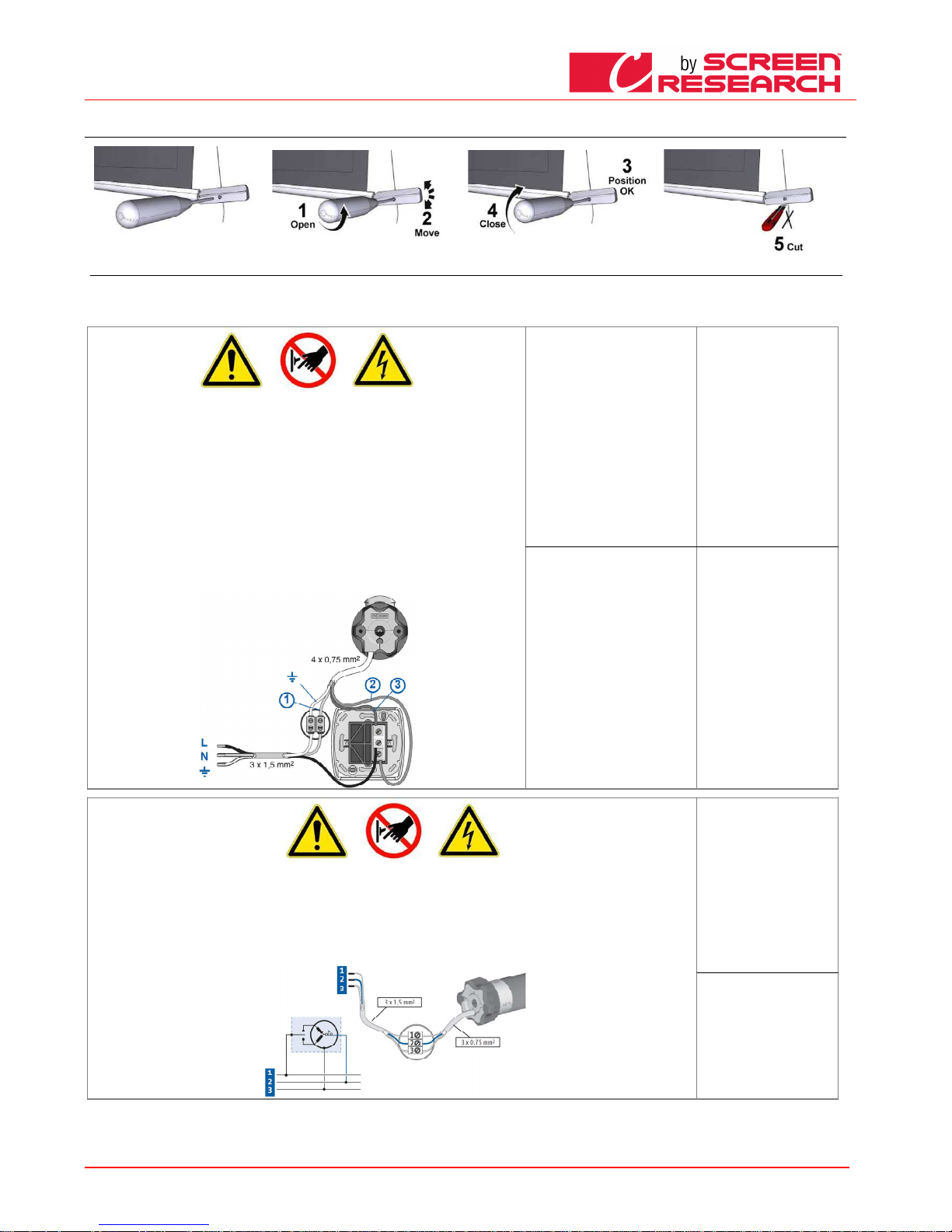
FRANCAIS - Manuel d’instructions écran
Made by Adeo Screen sp.
Z o.o. (Polska) Specifications a
re subject to change without notice. E&OE
Please verify that you are working with the latest revision of this document before specifying your screen.
Doc: Manual CLCTS-CLCLT rev5 | 03.02.2015| Download at: www.screenresearch.com 2015 AdeoSreen All Rights Reserved.
Page
12
08
08 08
08 REGLAGE DE CONTREPOIDS TENSIO SYSTEM
REGLAGE DE CONTREPOIDS TENSIO SYSTEMREGLAGE DE CONTREPOIDS TENSIO SYSTEM
REGLAGE DE CONTREPOIDS TENSIO SYSTEM
IDENTIFICATION DU TYPE DE MOTEUR
IDENTIFICATION DU TYPE DE MOTEUR IDENTIFICATION DU TYPE DE MOTEUR
IDENTIFICATION DU TYPE DE MOTEUR –––– CARACTÉRISTIQUES
CARACTÉRISTIQUES CARACTÉRISTIQUES
CARACTÉRISTIQUES –––– RACCORDEMENT ÉLECTRIQUE
RACCORDEMENT ÉLECTRIQUERACCORDEMENT ÉLECTRIQUE
RACCORDEMENT ÉLECTRIQUE
Le type de moteur installé sur le produit est identifié sur l’étiquette reportant le logo CE appliquée sur chaque produit. À l’ouverture de l’emballage, veuillez contrôler l’étiquette et identifier le modèle correct
du moteur afin d’effectuer l’installation et le câblage corrects de l’appareil. Au cas où la puissance du moteur ne correspondrait pas à la puissance du réseau électrique du lieu d’installation, veuillez
contacter un électricien et vous munir d’un transformateur de courant et Hz adapté.
RACCORDEMENT ÉLECTRIQUE:
RACCORDEMENT ÉLECTRIQUE:RACCORDEMENT ÉLECTRIQUE:
RACCORDEMENT ÉLECTRIQUE:
Le câblage électrique doit respecter les normes CEI en vigueur. La norme C EI EN 60335-1 prévoit que le réseau
d’alimentation doit être pourvu d’un dispositif de déconnexion omnipolaire avec une distance d’ouverture des
contacts d’au moins 3 mm. N’utiliser pour la commande de l’écran que le commutateur fourni avec l’appareil, ou un
modèle équivalent, en suivant les indications du schéma de raccordement (si le moteur est monté sur la gauche, les
couleurs des fils doivent être inversés, donc déroulement = marron, enroulement = noir). Le commutateur doit être
monté de manière à pouvoir l’actionner tout en ayant l’écran sous les yeux et à une hauteur comprise entre 1,5 et 1,8
m de hauteur du sol. Pour raccorder les câbles au commutateur fourni, enlever les plaques frontales pour accéder
aux commutateurs de blocage/déblocage.
ATTENTION:
ATTENTION:ATTE NTION:
ATTENTION:
l’exécution correcte des raccordements électriques, dans les règle de l’art et dans le respect des réglementations en
vigueur, est importante pour la prévention des accidents et afin de garantir un fonctionnement correct et durable de
l’écran.
Avant d’effectuer toute opération sur les parties électriques, s’assurer qu’il n’y a pas de tension.
Le moteur des écrans pourvus de caisson est situé sur la droite de l’écran vu de face (sur demande, il est possible de
l’avoir sur la gauche). Ne jamais relier deux moteurs ou plus à un même commutateur sans une commande de
groupe, ou bien deux commutateurs sur le même moteur.
230V 50Hz
230V 50Hz230V 50Hz
230V 50Hz
Caractéristiques moteur:
Caractéristiques moteur:Caractéristiques moteur:
Caractéristiques moteur:
Fréquence: ~Hz50
Puissance: 90W
Couple: 6Nm
Vitesse: 12Rpm
Nb max de cycles: 2
Longueur câble: 2.5m
Résistance mécanique:
conforme norme EN14202
Temp. de fonctionnement:
de –20 à +55 °C
Raccordement pour chaque
Raccordement pour chaque Raccordement pour chaque
Raccordement pour chaque
moteur
moteurmoteur
moteur ::::
Blau (Commun)
Marron (Montee)
Noir (Descente)
Jeune Vert (Terre 230V)
120V 60Hz
120V 60Hz120V 60Hz
120V 60Hz
Caractéristiques moteur:
Caractéristiques moteur:Caractéristiques moteur:
Caractéristiques moteur:
Fréquence: ~Hz60
Puissance: 80W
Couple: 88in.lb
Vitesse: 14r/min
Nb max de cycles: 2
Longueur câble: 2.5m
Résistance mécanique:
conforme norme EN14202
Temp. de fonctionnement:
de –20 à +55 °C
Raccordement pour chaque
Raccordement pour chaque Raccordement pour chaque
Raccordement pour chaque
moteur
moteurmoteur
moteur ::::
Blanc(Commun)
Noir (Descente)
Rouge (Montee)
Jeune Vert (Terre 120V)
RACCORDEMENT ÉLECTRIQUE:
RACCORDEMENT ÉLECTRIQUE:RACCORDEMENT ÉLECTRIQUE:
RACCORDEMENT ÉLECTRIQUE:
Le câblage électrique doit respecter les normes CEI en vigueur. La norme CEI EN 60335-1 prévoit que le réseau d’alimentation doit être pourvu d’un dispositif de
déconnexion omnipolaire avec une distance d’ouverture des contacts d’au moins 3 mm. Pour chaque moteur (par ex. interrupteur prise etc.) En cas de besoin, ce
dispositif garantit une déconnexion rapide et sûre de l’alimentation électrique. Utiliser des câbles pour la connexion comme l’illustre l’image.
ATTENTION:
ATTENTION:ATTENTION:
ATTENTION: l’exécution correcte des raccordements électriques, dans les règle de l’art et dans le respect des réglementations en vigueur, est importante pour la
prévention des accidents et afin de garantir un fonctionnement correct et durable de l’écran.
Avant d’effectuer toute opération sur les parties électriques, s’assurer qu’il n’y a pas de tension.
Le moteur des écrans pourvus de caisson est situé sur la droite de l’écran vu de face (sur demande, il est possible de l’avoir sur la gauche).
L’actionnement se fait à travers une radiocommande fournie de série.
SSSSomfy RTS 230V 50Hz
omfy RTS 230V 50Hzomfy RTS 230V 50Hz
omfy RTS 230V 50Hz
Caractéristiques Moteur
Caractéristiques MoteurCaractéristiques Moteur
Caractéristiques Moteur ::::
Fréquence: ~Hz50
Puissance: 120W
Couple: 10Nm
Vitesse: 17Rpm
Nb max de cycles: 2
Longueur câble: 3m
Temp. de fonctionnement:
de –20 à +55 °C
Fréquence: 433.92 MHz
Portée émetteur: 150m
Raccordement pour chaqu
Raccordement pour chaquRaccordement pour chaqu
Raccordement pour chaque
e e
e
moteur
moteurmoteur
moteur ::::
Marron (Phase 230V)
Bleu (Neutre 230V)
Jaune Vert (Terre 230V)
Page 13
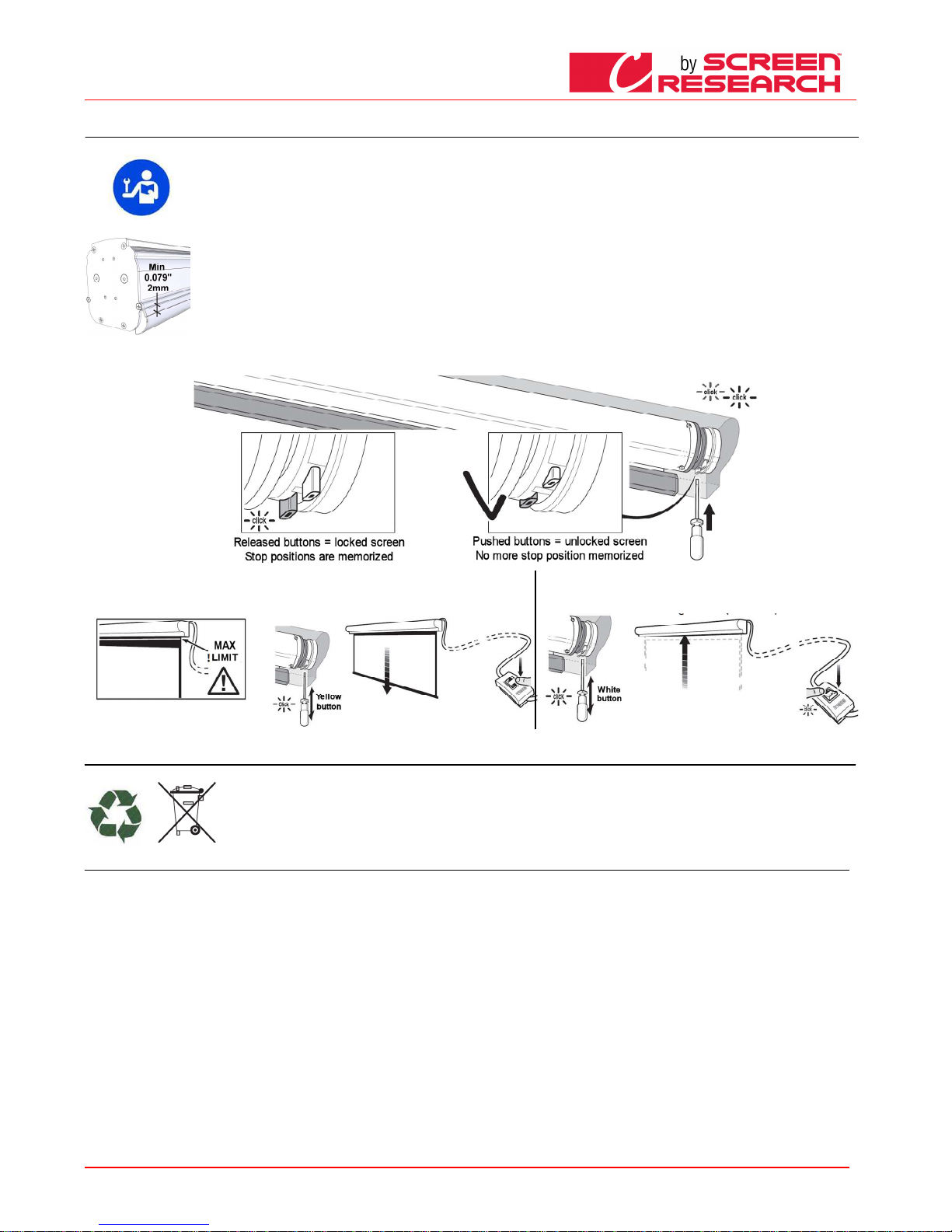
FRANCAIS - Manuel d’instructions écran
Made by Adeo Screen sp.
Z o.o. (Polska) Specifications a
re subject to change without notice. E&OE
Please verify that you are working with the latest revision of this document before specifying your screen.
Doc: Manual CLCTS-CLCLT rev5 | 03.02.2015| Download at: www.screenresearch.com 2015 AdeoSreen All Rights Reserved.
Page
13
10
10 10
10 RÉGLAGE DES FINS DE COURSE
RÉGLAGE DES FINS DE COURSERÉGLAGE DES FINS DE COURSE
RÉGLAGE DES FINS DE COURSE
ATTENTION: À LIRE A VANT D’EFFECTUER TOUT RÉGLAGE
ATTENTION: À LIRE A VANT D’EFFECTUER TOUT RÉGLAGEATTENTION: À LIRE A VANT D’EFFECTUER TOUT RÉGLAGE
ATTENTION: À LIRE A VANT D’EFFECTUER TOUT RÉGLAGE
Les réglages indiqués n e peuvent être effectués que par un technicien autori sé et spécialisé. Le non respect des procédures décrites peut provoquer des dommages au produit,
pour lesquels la garanti e ne sera pas valable.
RISQUES
RISQUESRISQUES
RISQUES
LA FIN DE COURSE SUPÉ RIEURE DOIT TOUJOURS ÊTRE RÉGLÉE À 2mm DU C AISSON (voir image à droite).
La fin de course est rég lée de manière à permettre que la toile de project ion reste enroulée sur au moins 1,5 tours autour du rouleau afin d’éviter le décrochage de la toile. Une
attention particulière do it être accordée en cas de réglage des fins de course au-delà du réglage d’usine de déroulement de la toile de projection. Un mauvais réglage des fins
de course peut provoqu er :
-Décrochage de la toile de projection du rouleau.
-Enroulement en sens c ontraire de la toile de projection avec endommageme nt de la surface de l’écran et des mécanismes d’enroule ment.
-Rupture de la soudure du bord noir en bas (écrans avec bord).
-Effort excessif du mote ur avec risque d’endommagement et de décle nchement de la résistance thermique contenue dans celu i-ci.
-Enroulement excessif d u système de réglage des fins de course et rupture de la partie mécanique.
GARANTIE
GARANTIEGA RANTIE
GARANTIE
Nous rappelons aux opé rateurs qu’en cas de modification des protections et d’endommagement dû à un réglage incorrect, les interv entions de réparation seront considérées
hors garantie.
-
Poussé-les boutons blanc et jaune pour débloqué les positions de fin d'arrêt.
-Déplacez le tissu de projection dans la position finale vers le bas, ATTENTION faire pour ne pas dépasser la
limite spécifiée dans la toile de projection et relâchez le bouton jaune
-Déplacez le tissu de projection dans la position finale vers le haut, et
relâchez le bouton blanc
ÉLIMINATION DU PRODUIT
ÉLIMINATION DU PRODUITÉLIMINATION DU PRODUIT
ÉLIMINATION DU PRODUIT
Comme pour les opérations d'installation, au terme de la vie du produit, les opérations de démontage doivent être effectuées par un technicien qualifié.
Ce produit est composé de différents types de matériaux : certains peuvent être recyclés, d’autres doivent être éliminés. Informez-vous sur les systèmes de recyclage et
d’élimination des déchets prévus par les réglementations en vigueur sur votre territoire pour cette catégorie de produits.
Comme l’indique le symbole ci-contre, il est interdit de jeter ce produit dans les déchets domestiques. Effectuez donc un "tri sélectif" pour le traitement des déchets,
selon les méthodes prévues par les réglementations en vigueur sur votre territoire, ou bien ramenez le produit chez le vendeur au moment de l'achat d’un nouveau
produit équivalent. Attention: les réglementations locales peuvent prévoir des sanctions en cas d’élimination abusive de ce produit
GARANTIE
GARANTIEGARANTIE
GARANTIE
1.GARANTIE
1.GARANTIE1.GARANTIE
1.GARANTIE ScreenResearch garantit que le produit fabriqué est exempt de tout défaut de fabrication dans les matériaux et dans les usinages, conformément aux termes et conditions ci-après. Les toiles de
projection et les profils sont garantis pour une période de cinq (5) ans à compter de la date de la facture originale. Moteurs, commandes moteur, télécommandes, et matéri
el de montage sont garantis trois (3)
ans à compter de la date de la facture originale.
2.CONDITIONS ET LIMITATIONS
2.CONDITIONS ET LIMITATIONS2.CONDITIONS ET LIMITATIONS
2.CONDITIONS ET LIMITATIONS La présente garantie est soumise aux conditions et limitations suivantes. La garantie est nulle et inapplicable si le produit a été utilisé ou manipulé de manière non conforme
au manuel d’instructions contenu dans l’emballage du produit, s’il est mal utilisé ou utilisé de manière impropre, s’il a été endommagé par accident ou par négligence pendant le transport, ou si le défaut est
dû à des réparations ou modifications effectuées par un personnel non autorisé. Le produit doit être installé par un professionnel dûment autorisé par ScreenResearch et les opérations d’entretien indiquées
dans le manuel doivent être exécutées régulièrement.
3.RETOURS DE MARCHANDISE
3.RETOURS DE MARCHANDISE3.RETOURS DE MARCHANDISE
3.RETOURS DE MARCHANDISE Aucun produit restitué ne sera accepté sans autorisation écrite (RMA) de la part de ScreenResearch. Le produit doit être retourné emballé dans son emballage original ou
équivalent, afin d’éviter tout endommagement pendant le transport. Le produit doit être emballé et restitué à ScreenResearch ou à un centre de réparation autorisé, à la charge du client. Les frais de
restitution du produit sont à la charge de ScreenResearch. Le produit restitué doit être accompagné d’une description écrite du défaut et d’une photocopie du reçu original d’achat. Ce reçu doit indiquer
clairement la liste des modèles et le numéro de série, la date d’achat, le nom et l'adresse de l'acheteur et du revendeur autorisé, et le prix payé par l'acheteur. ScreenResearch se réserve le droit de modifier
le design de tout produit, sans aucune obligation par rapport aux produits fabriqués précédemment, et de modifier les prix ou les spécifications de tout produit sans préavis ou obligation d’aucune sorte.
4.SOLUTIONS
4.SOLUTIONS4.SOLUTIONS
4.SOLUTIONS Au cas où le produit ne serait pas conforme à la garantie ci-dessus, l'unique solution pour l’acheteur selon les dispositions de la présente Garantie Limitée est de restituer le produit à
ScreenResearch ou à un centre de recherche autorisé. La non-conformité sera rectifiée sans frais de main d’œuvre ni frais de substitution des composants.
5.LIMITE AU PREMIER ACHETEUR
5.LIMITE AU PREMIER ACHETEUR5.LIMITE AU PREMIER ACHETEUR
5.LIMITE AU PREMIER ACHETEUR Cette garantie n’est valable que pour le premier acheteur du produit et ne peut pas être transférée à un acheteur successif du produit.
6.DIVERS
6.DIVERS6.DIVERS
6.DIVERS Toutes les garanties implicites relatives aux produits ScreenResearch sont limitées à la durée de cette garantie. La garantie ne s’étend pas à d’éventuels dommages directs ou indirects à l'acheteur.
Certains pays ne permettent pas de limitations sur la durée d’une garantie implicite ou l'exclusion ou la limitation des dommages accidentels ou conséquents ; les susdites limitations ou exclusions
pourraient donc ne pas être applicables. Cette garantie confère des droits légaux spécifiques, et il est également possible d’obtenir d’autres doits en fonction du pays de résidence.
7.DEMANDES
7.DEMANDES7.DEMANDES
7.DEMANDES Pour toute demande concernant la garantie limitée ci-dessus, veuillez vous adresser au revendeur autorisé ScreenResearch.
8. ASSISTANCE SOUS GARANTIE GÉRÉE PAR LES DISTRIBUTEURS AUTORISÉS
8. ASSISTANCE SOUS GARANTIE GÉRÉE PAR LES DISTRIBUTEURS AUTORISÉS8. ASSISTANCE SOUS GARANTIE GÉRÉE PAR LES DISTRIBUTEURS AUTORISÉS
8. ASSISTANCE SOUS GARANTIE GÉRÉE PAR LES DISTRIBUTEURS AUTORISÉS Screen Research autorise la distribution de ses produits dans de nombreux pays du monde. Pour chaque pays, le distributeur
autorisé/importateur est responsable de l'assistance sous garantie des produits vendus dans son pays. Le service de garantie doit être revendiqué auprès du revendeur, importateur ou distributeur, auprès
duquel le produit a été acheté.
Page 14
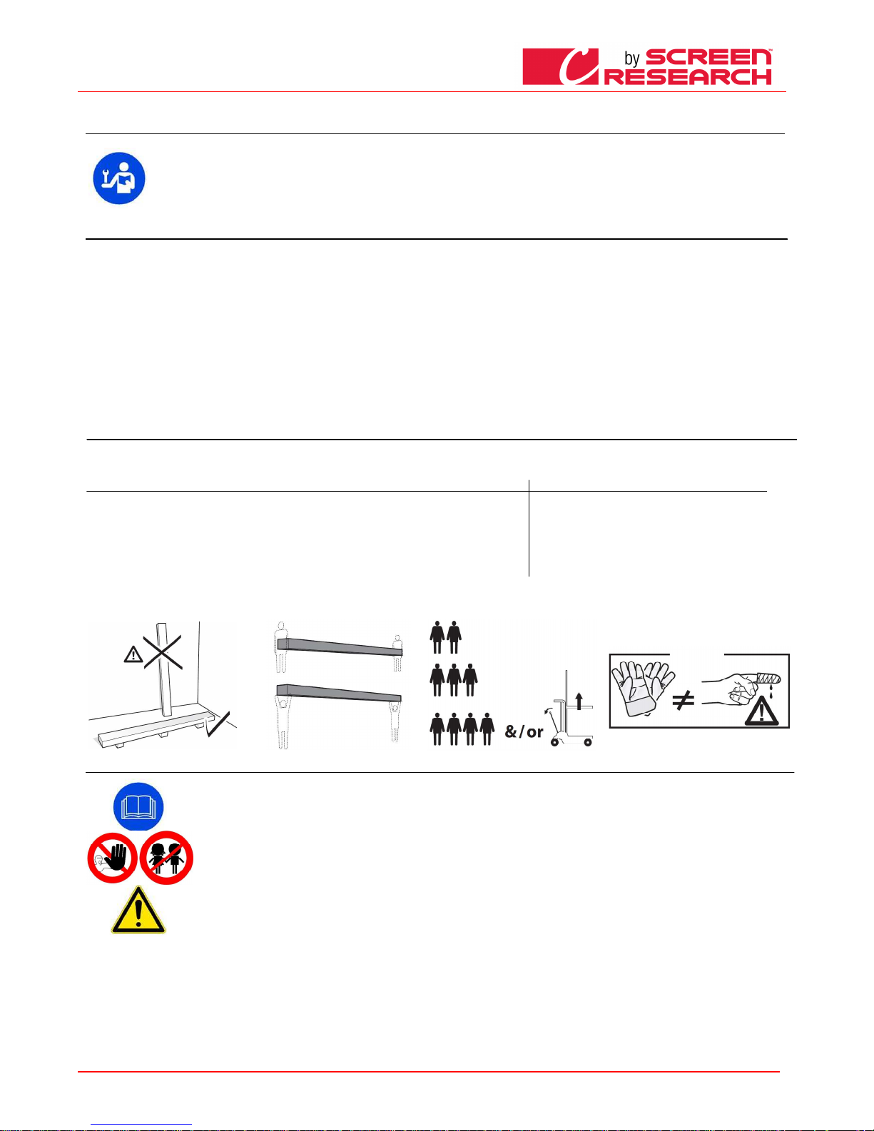
DEUTSCH - Betriebsanleitung Projektionswand
Made by Adeo Screen sp.
Z o.o. (Polska) Specifications a
re subject to change without notice. E&OE
Please verify that you are working with the latest revision of this document before specifying your screen.
Doc: Manual CLCTS-CLCLT rev5 | 03.02.2015| Download at: www.screenresearch.com 2015 AdeoSreen All Rights Reserved.
Page
14
01
01 01
01 EINFÜHRUNG
EINFÜHRUNGEINFÜHRUNG
EINFÜHRUNG
Dieses Handbuch ist integraler Teil des Prod ukts, und dessen Lektüre und Verständnis sind von wesentlicher Bedeutung für die Sicherheit. Darin sind die Normen und
Verwendungsmodalitäten beschrieben, die dem Kunden eine richtige und sichere Nutzung der Projektionswand ermöglichen. D as Handbuch muss stets beim Produkt verbleiben und ist
sorgfältig an einem geeigneten Ort aufzube wahren, um seine Unversehrtheit zu gewährleisten und allen berechtigten Personen zur Hinz uziehung zugänglich zu sein. Jeder Nutzer des
Produkts ist für den Schutz des Handbuchs verantwortlich. Außerdem ist er für die Überprüfung der Funktionstüchtigkeit der Projektio nswand und für alle Reparaturen und den
Austausch von abgenützten Teilen, die Schä den verursachen könnten.
Die in diesem Handbuch enthaltenen B ilder dienen dazu, Funktionen, Eigenschaften und Verfahren im Detail zu zeigen. Trotzdem k önnen sie sich je nach dargestelltem Modell
unterscheiden, wobei sich jedoch die B edeutung des Bildes im Hinblick auf den beschreibenden Zweck nicht ändert
02 ALLGEMEINE PRODUKTEIGENSCHAFTEN
02 ALLGEMEINE PRODUKTEIGENSCHAFTEN02 ALLGEMEINE PRODUKTEIGENSCHAFTEN
02 ALLGEMEINE PRODUKTEIGENSCHAFTEN
Die Projektionswände werden in Übere instimmung zu folgenden CE-Richtlinien hergestellt 2006-95-CE LDV
2004-108-CE EMC
1999-05-CE R&TTE
2005-32-CE Eco design
2011-65-CE ROHS
2002-96-CE RAEE
2001-95-CE Seafty
Die in diesem Handbuch beschriebene Projektionswand darf nur als Bildwand für die Videoprojektion verwendet werden. Jede andere, nicht in diesem Handbuch vorgesehene Verwendung ist unzulässig.
Die Projektionswand enthält eines ode r mehrere Projektionstücher aus cadmiumfreiem PVC oder aus PVC-imprägnierter GLASFASER. Jedes Tuch kann in folgende Baustoffklassen eingeteilt werden:
- M1 und M2 gemäß den französi schen Bestimmungen (LNE Laboratoire national de métrologie et d’essais – SME Centre de recher ches du Bouch et - WAR
RINGTONFIRE G ENT Laboratoire d e
métrologie et d’essais – IFTH Laborato ire accreditè )
- B1 und B2 gemäß den deutschen Bestimmungen (LNE Laboratoire national d e métrologie et d’essais – SME Centre de recher ches du Bouchet - WARRINGTONFIRE GENT Laboratoire nat
ional de
métrologie et d’essais)
- UL94HB gemäß den US-amerikanisc hen Bestimmungen (THE GOVMARK Organization, Inc.)
Da es noch keine europaweite Harmonisierung der ve rschiedenen nationalen Einstufungsnormen gibt, wird darauf hingewiesen, dass die französisch
e Klasse M1 nicht entzündlichem Material, und die Kla sse
M2 schwer entzündlichem Material en tspricht.
03 AUSPACKEN DER PROJEKTIONSWAND UND HANDLING DES PRODUKTES
03 AUSPACKEN DER PROJEKTIONSWAND UND HANDLING DES PRODUKTES03 AUSPACKEN DER PROJEKTIONSWAND UND HANDLING DES PRODUKTES
03 AUSPACKEN DER PROJEKTIONSWAND UND HANDLING DES PRODUKTES
Stellen Sie sicher, dass während des Transports kein Teil der Leinwand beschädigt wurde. Bei Auffälligkeiten ist umgehend der Händler zu informieren. Überprüfen Sie, ob alle Zubehörteile für die
nachfolgend beschriebene Leinwand mitgeliefert wurden.
Projektionswand mit motorbetriebenem Wickelmechanismus oder integriertem Funkempfänger
Projektionswand mit motorbetriebenem Wickelmechanismus oder integriertem FunkempfängerProjektionswand mit motorbetriebenem Wickelmechanismus oder integriertem Funkempfänger
Projektionswand mit motorbetriebenem Wickelmechanismus oder integriertem Funkempfänger
Projektionswand mit Kurbelwicklung
Projektionswand mit KurbelwicklungProjektionswand mit Kurbelwicklung
Projektionswand mit Kurbelwicklung
-
2 Bügelsets für die Installation (für Projektionswände bis zu einer Breite
von 3 m)
-3 Bügelsets für die Installation (für Projektionswände mit einer Breite über 3 m)
-2 Seitliche Bügel (für Projektionswände ohne Gehäuse)
-1 einpoliger Umschalter 10 A, 250 V, Totmannschalter mit Richtungspfeilen, einschließlich Kappe für die Wandmontage
-1 Funkfrequenzsender (für Projektionswände mit integriertem Funkempfänger)
-1 Inbusschlüssel aus Kunststoff
-1 Gebrauchsanleitung
(ohne Schrauben und Dübel für die Wandbefestigung)
2 Bügelsets für die Installation (für Projektionswände bis
zu einer
Breite von 3 m)
-3 Bügelsets für die Installation (für Projektionswände mit einer
Breite über 3 m)
-1 Bedienstange mit Kurbel
-1 Gebrauchsanleitung
(ohne Schrauben und Dübel für die Wandbefestigung)
AAAACHTUNG:
CHTUNG:CHTUNG:
CHTUNG: Zum Öffnen der Verpackung keine Teppichmesser oder spitzen Gegenstände verwenden. Beim Öffnen der Verpackung, sowie bei Installation und Handling des Produktes immer
Schutzhandschuhe tragen. Das Produkt muss je nach Gewicht von mindestens zwei, drei oder vier Personen befördert werden (Richtwerte für die Last pro Person: 25 kg Männer - 15 kg Frauen). Bei höheren
Gewichten wird empfohlen, spezifisches Hebezeug verwenden
04 ALLGEMEINE SICHERHEITSVORSCHRIFTEN
04 ALLGEMEINE SICHERHEITSVORSCHRIFTEN04 ALLGEMEINE SICHERHEITSVORSCHRIFTEN
04 ALLGEMEINE SICHERHEITSVORSCHRIFTEN
Lesen Sie die Anleitungen und Hinweise dieser Gebrauchsanleitung vor Verwendung des Produkts oder Durchführung jeglicher Art von Wartung und versichern Sie sich, dass
Sie sie verstanden haben. Installation des Bildschirms über Durchgangszone ist streng verboten.
Überprüfen Sie vor und während der Verwendung, dass die Projektionswand keine gefährlichen Situationen erzeugt.
Keines der Elemente oder Teile der Projektionswand beschädigen oder entfernen.
Führen Sie niemals Wartungseingriffe an der Projektionswand mit laufendem Motor durch (sicherheitshalber die Stromzufuhr abtrennen).
Das Produkt darf unter keinen Umständen von Kindern benutzt werden. Kinder dürfen sich der Projektionswand unter keinen Umständen nähern, solange diese sich bewegt.
Jede Projektionswand ist durch eine Garantie gedeckt, deren Gültigkeit von der tatsächlichen Einhaltung der Anleitungen in diesem Handbuch abhängt.
ACHTUNG:
ACHTUNG:ACHTUNG:
ACHTUNG: Eine falsche Installation kann die Sicherheit der Anwender des Produkts beeinträchtigen. Der Hersteller lehnt jegliche Haftung für Personen- bzw. Sachschäden ab,
die auf unsachgemäße Benutzung, Montagefehler oder ungenügende Wartung zurückzuführen sind.
Der Hersteller haftet nicht für Probleme, die durch Installationsfehler verursacht werden.
Die Montage der Leinwand, die elektrischen Anschlüsse und die Überprüfungen bei Störungen der motorbetriebenen Wicklungen sind von einem hierzu befugten Händler oder
von Fachpersonal durchzuführen, das Kenntnis von den Gefahren hat, die von elektrischer Energie ausgehen. Das Anschlusskabel kann nicht ersetzt werden. Bei
Beschädigung des Kabels muss die gesamte Leinwand ausgetauscht werden. Eingriffe an den Endschaltern oder das Aufbrechen der angebrachten Siegel führen zu
Garantieverlust. Bei Rückfragen wenden Sie sich bitte an unser technisches Büro.
NACH DER MONTAGE DES BILDSCHIRMS AN DEN BÜGELN IST VOR DER VERWENDUNG SICHERZUSTELLEN, DASS DER BILDSCHIRM PERFEKT HORIZONTAL POSITIONIERT IST.
Page 15
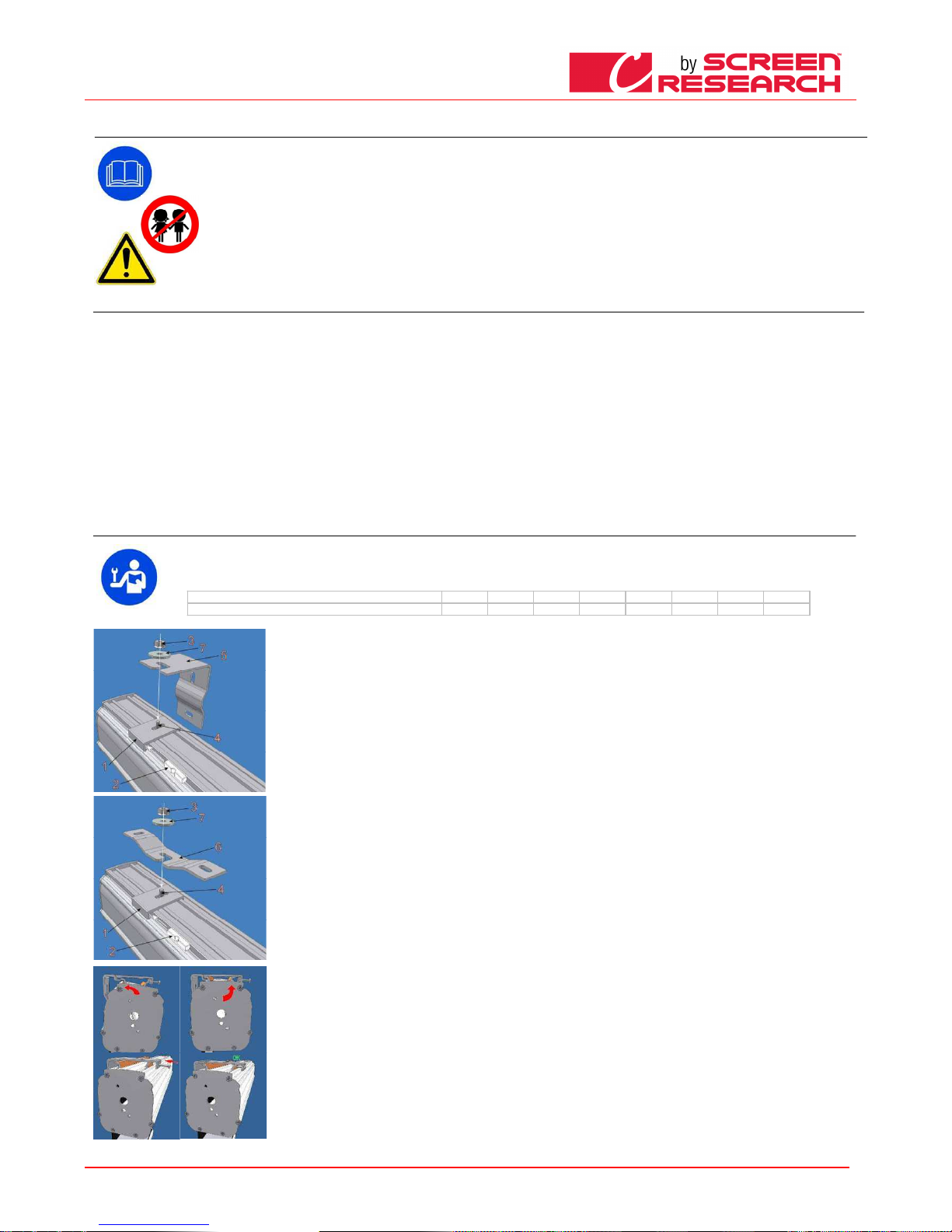
DEUTSCH - Betriebsanleitung Projektionswand
Made by Adeo Screen sp.
Z o.o. (Polska) Specifications a
re subject to change without notice. E&OE
Please verify that you are working with the latest revision of this document before specifying your screen.
Doc: Manual CLCTS-CLCLT rev5 | 03.02.2015| Download at: www.screenresearch.com 2015 AdeoSreen All Rights Reserved.
Page
15
05
05 05
05 HINWEISE UND VORSICHTSMASSNAHMEN FÜR DEN GEBRAUCH
HINWEISE UND VORSICHTSMASSNAHMEN FÜR DEN GEBRAUCHHINWEISE UND VORSICHTSMASSNAHMEN FÜR DEN GEBRAUCH
HINWEISE UND VORSICHTSMASSNAHMEN FÜR DEN GEBRAUCH
Die Leinwände sind für die Benutzung in Innenräumen unter normalen Temperatur- (20 - 25 °C) und Feuchtigkeitsbedingungen vorgesehen. Bei Einsatz im Außenbereich sind
besondere Vorsichtsmaßnahmen, vor allem hinsichtlich Temperatur und Staubbelastung, zu treffen. Bei einer Exposition der Leinwand gegenüber Temperaturen von über 50
°C, kann es zu einer dauerhaften Verformung der Ebenheit sowie zur Ablösung der Leinwand von der Aufwickelrolle kommen. Die Leinwand nicht längere Zeit dem Sonnenlicht
aussetzen, um ein Vergilben zu vermeiden (außerdem sicherstellen, dass die Leinwand die oben angegebene Temperatur durch Sonnenbestrahlung nicht übersteigt).
Da das Material, aus dem die Leinwand besteht (PVC), zur elektrostatischen Aufladung neigt, kann sich bei übermäßigem Staubanfall in der Umgebung durch die
elektrostatische Anziehung dieser Staub auf der Leinwand ablagern und zu einer Beeinträchtigung ihrer optischen Eigenschaften führen (siehe auch Reinigung der Leinwand).
ACHTUNG:
ACHTUNG:ACHTUNG:
ACHTUNG: Die Leinwand nicht gewaltsam von Hand herausziehen, da dadurch der Motor beschädigt oder der Bügelkasten abgerissen werden könnte.
Erlauben Sie Kindern nicht, mit den fest angebrachten Steuervorrichtungen zu spielen.
Beobachten Sie die Leinwand und halten Sie Personen davon fern, bis die Projektionswand völlig geschlossen ist.
Es ist verboten, die Bewegung der Leinwand zu blockieren, zu verhindern oder zu erzwingen, sich an der Leinwand oder an der unteren Schiene festzuhalten oder daran zu
schaukeln, Gegenstände an der Leinwand oder an der unteren Schiene anzubringen oder die Struktur der Leinwand zu ändern, da dies zu Schäden am Aufwickelsystem und
somit zu Personen- und Sachschäden führen kann
06
06 06
06 REINIGUNG UND WARTUNG
REINIGUNG UND WARTUNGREINIGUNG UND WARTUNG
REINIGUNG UND WARTUNG
Die Projektionswände u nd deren Projektionstücher sind sehr empfindlic h, daher müssen sie besonders sorgfältig behandelt und unt er Befolgung der nachstehenden Hinweise gepf legt werden:
Zum Reinigen der Oberf läche keine Lösungsmittel, Chemikalien oder Scheuerm ittel und keine spitzen Utensilien benutzen.
Jeden Kontakt mit ande ren Materialien (Lacke, Tinten usw.) vermeiden, da sic h diese möglicherweise nicht mehr von dem Gewebe
entfernen lassen.
PROJEKTIONSTÜCHE R CLEARPIX
PROJEKTIONSTÜCHE R CLEARPIXPROJ EKTIONSTÜCHER CLEARPIX
PROJEKTIONSTÜCHE R CLEARPIX: Verwenden Sie ein weiches , sauberes und leicht angefeuchtetes Tuch und bew egen Sie es immer von der Mitte des Projektionsberei chs nach außen. Ein Bürstenaufsatz am
Staubsauger darf nur be nutzt werden, wenn die Borsten weich und perfekt sa uber sind.
PROJEKTIONSTÜCHE R
PROJEKTIONSTÜCHE R PROJEKTIONSTÜCHER
PROJEKTIONSTÜCHE R SSSSOLIDPIX, MULTI PIX,
OLIDPIX, MULTIPIX, OLIDPIX, MULTIPIX,
OLIDPIX, MULTIPIX, : Per p ulire telo di proiezione, utilizzare un panno morb ido, pulito, inumidito, eventualmente abbinato con detergenti a base neutra o alcool. Poiché dopo la pulizia
potrebbe verificarsi che il telo si carichi di elettricità statica, a causa dello sfre gamento con il panno, si consiglia di passare, con un pa nno pulito, un liquido antistatico sul telo per evitare che la polvere venga
nuovamente attratta da llo stesso.
PROJEKTIONSTÜCHE R SILVERPIX
PROJEKTIONSTÜCHE R SILVERPIX P ROJEKTIONSTÜCHER SILVERPIX
PROJEKTIONSTÜCHE R SILVERPIX ist obligatorisch, um die Anleitung für da s Gewebe Bildschirm lesen
PROFIL
PROFILPROFIL
PROFILEEEE:::: Das Gehäuse ist mit ei nem weichen, sauberen Tuch abzustauben und gegebe nenfalls mit einem milden Reinigungsmittel zu r einigen.
PROFILE MIT SAMTBEZU G:
PROFILE MIT SAMTBEZU G:PROFILE MIT SAMTBEZUG:
PROFILE MIT SAMTBEZU G: Zur Pflege des Profils wird d ieses mit einem weichen, sauberen Tuch oder mit einer B ürste mit weichen, antistatischen Borsten abgestaubt . Ein Bürstenaufsatz am Staubsauger
darf nur benutzt werden , wenn die Borsten weich und perfekt sauber sind.
STRUKTUR und BEFESTI GUNGSBÜGEL:
STRUKTUR und BEFESTI GUNGSBÜGEL: STRUKT UR und BEFESTIGUNGSBÜGEL:
STRUKTUR und BEFESTI GUNGSBÜGEL: Der Zustand des Produkts und d er Halt der Befestigungsbügel müssen regelmäßig kontrollie rt werden. Sind Verbiegungen, Risse oder Materiale rmüdung von Bügeln,
Schrauben oder Bauteil en des Produkts festzustellen, muss die Umgebu ng der Projektionswand abgesichert werden, um Sach- und Personenschäden zu vermeiden. Anschließend das anscheinend defekte
Teil sofort ersetzen und das Produkt wieder herstellen.
07
07 07
07 MONTAGEANLEITUNG
MONTAGEANLEITUNGMONTAGEANLEITUNG
MONTAGEANLEITUNGIIII
ACHTUNG:
ACHTUNG:ACHTUNG:
ACHTUNG: Es ist absolut verboten, den Bildschirm auf mobilen Wänden oder instabile Leitungen verlegen, müssen die Klammern auf Oberflächen, die in der Zeit sicherzustellen, dass
Ihre distanz angewendet werden. Die Montage der Projektionswand hat mit Schrauben und Dübeln zu erfolgen, die für das Gewicht und die Art der Wand oder der Decke geeignet sind,
an der die Bügel befestigt werden sollen. Vor Beginn der Installation, wählen Sie den Dübel oder das Befestigungssystem nach dem folgenden Schema
Breite Projektionswand bis (cm)
Breite Projektionswand bis (cm)Breite Projektionswand bis (cm)
Breite Projektionswand bis (cm)
160
160160
160
200
200200
200
250
250250
250
300
300300
300
360
360360
360
410
410410
410
520
520520
520
620
620620
620
Zu berücksichtigendes Gesamtgewicht
Zu berücksichtigendes GesamtgewichtZu berücksichtigendes Gesamtgewicht
Zu berücksichtigendes Gesamtgewicht
Kg 20
Kg 20Kg 20
Kg 20
Kg 25
Kg 25Kg 25
Kg 25
Kg 30
Kg 30Kg 30
Kg 30
Kg 35
Kg 35Kg 35
Kg 35
Kg 45
Kg 45Kg 45
Kg 45
Kg 50
Kg 50Kg 50
Kg 50
Kg 100
Kg 100Kg 100
Kg 100
Kg 150
Kg 150Kg 150
Kg 150
WANDBEFESTIGUNG:
WANDBEFESTIGUNG:WANDBEFESTIGUNG:
WANDBEFESTIGUNG:
die Schraube 4 mit dem Gewinde nach oben in die Platte 1 einführen und die Mutter 3 ein wenig aufschrauben, ca. 4-5 mm Spiel lassen; die Platte 1 in das
Gehäuse einhaken und den Kunststoffstift 2 in die Aussparung des Bügels einsetzen. Für die Montage ist es nicht von Bedeutung, in welcher Richtung die
Platte angebracht wird, da die Profile des Gehäuses vollkommen symmetrisch sind. Den Bügel 5 mit für den Mauertyp geeigneten Expansionsdübeln
(mindestens Ø 8 mm) an der Wand befestigen und die Platte 1 mit der Unterlegscheibe 7 und dem Bolzen 3 am Bügel 5 befestigen.
DECKENMONTAGE:
DECKENMONTAGE: DECKENMONTAGE:
DECKENMONTAGE:
Die serienmäßig mit der Leinwand mitgelieferten Deckenbügel 6 mit für den Mauertyp geeigneten Expansionsdübeln (mindestens Ø 8 mm) in einem
Abstand von ca. 10 - 15 cm vom Gehäuses befestigen. Bei Leinwänden mit einer Breite von über 350 cm wird der dritte Bügel in der M itte des Gehäuses
angebracht. Die Schraube 4 mit dem G ewinde nach oben in die Platte 1 stecken, die Mutter 3 ein wenig aufschrauben und 4-5 mm Spiel lassen; die Platte
1 in das Gehäuse einhaken und den Kunststoffstift 2 in die Aussparung des Bügels einsetzen. Die Platte 1 mit der Scheibe 7 und dem Bolzen 3 am Bügel 6
befestigen:
Die Halterungsplatten 1 können direkt an der Decke verankert werden, wenn gewünscht wird, dass die Projektionswand möglichst nahe an der Decke
befestigt wird (für eine einfache und schnelle Montage muss die b etreffende Decke vollkommen eben sein und die Platten müssen perfekt ausgerichtet
werden). Die Platten sind mit geeigneten Expansionsdübeln (mindestens Ø 8 mm) in einem Abstand von ca. 10 - 15 cm vom Gehäuses befestigen. Bei
dieser Montageart sollte die Seite der Platte für den Fixierstift üblicherweise zur Vorderseite des G ehäuses hingedreht werden, um das Einsetzen des Stiftes
zu erleichtern. Die Ausrichtung und die völlig waagerechte Pos ition der Platten orgfältig kontrollieren. Dazu können die in der Packung enthaltenen
Metallscheiben verwendet werden. Achtung: von der sorgfältigen Ausführung dieses Arbeitsschrittes hängt es ab, ob das Gehäuse anschließend schnell und
einfach eingehängt werden kann. Bei Leinwänden mit e iner Breite von ü ber 350 cm w ird der dritte Bügel in der Mitt e des Gehäuses angebracht. Das
Gehäuse mit einer halben Drehung in die Platten einsetzen (einrasten lassen) und die Kunststoffstifte einstecken, mit denen die Befestigung des Gehäuses
an den Platten sichergestellt wird
KASTEN VAR SCHNELL
KASTEN VAR SCHNELLKASTEN VAR SCHNELL
KASTEN VAR SCHNELL
1) Die Bügel mit geeigneten Expansionsdübeln (mindestens Ø 8 mm) befestigen (kann an der Wand oder an der Decke befestigt werden), die Ausrichtung
kontrollieren;
2) die Projektionswand an den Bügeln befestigen .
Page 16
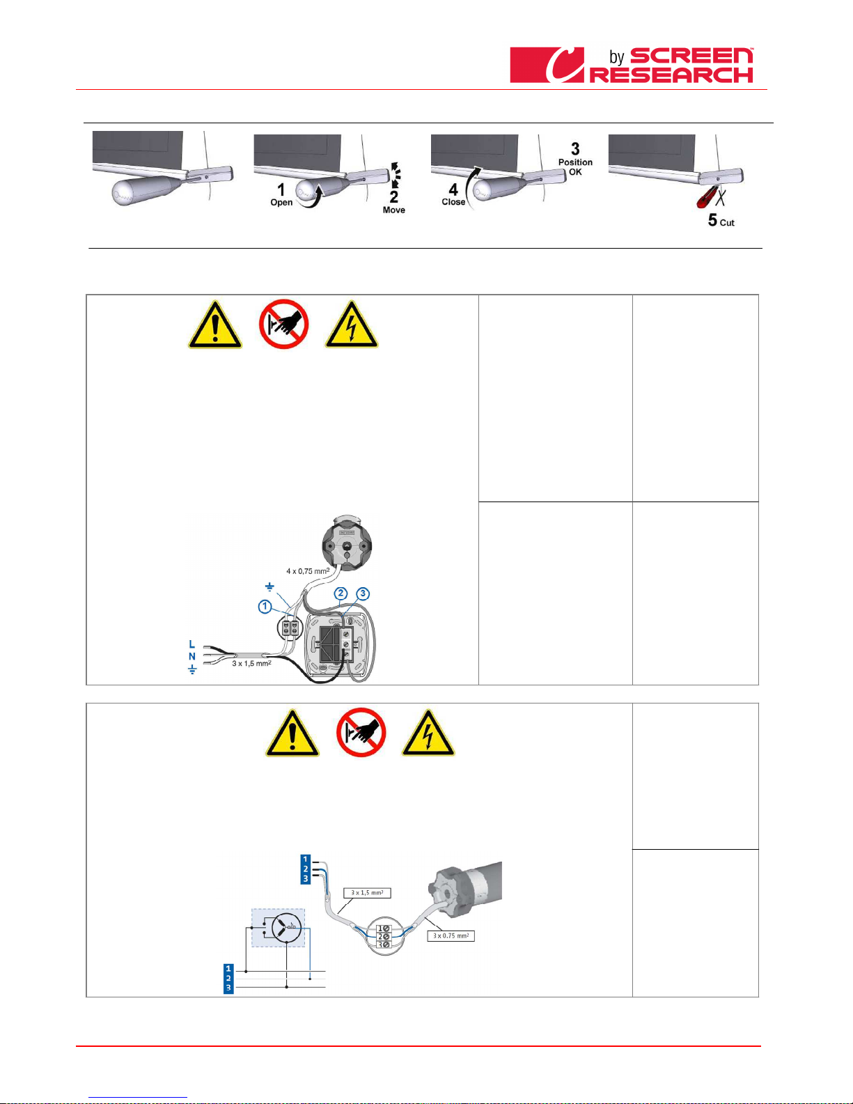
DEUTSCH - Betriebsanleitung Projektionswand
Made by Adeo Screen sp.
Z o.o. (Polska) Specifications a
re subject to change without notice. E&OE
Please verify that you are working with the latest revision of this document before specifying your screen.
Doc: Manual CLCTS-CLCLT rev5 | 03.02.2015| Download at: www.screenresearch.com 2015 AdeoSreen All Rights Reserved.
Page
16
08
08 08
08 GEWICHTSEINSTELLUNG
GEWICHTSEINSTELLUNGGEWICHTSEINSTELLUNG
GEWICHTSEINSTELLUNG
09 KENNUNG DES MOTORTYPS
09 KENNUNG DES MOTORTYPS 09 KENNUNG DES MOTORTYPS
09 KENNUNG DES MOTORTYPS –––– FEATURES
FEATURES FEATURES
FEATURES ---- ELEKTRISCHER ANSCHLUSS
ELEKTRISCHER ANSCHLUSSELEKTRISCHER ANSCHLUSS
ELEKTRISCHER ANSCHLUSS
Der am Produkt installierte Motortyp ist auf dem an jedem Produkt angebrachten Typenschild mit dem CE-Logo angegeben. Bei Öffnen der Verpackung muss dieses Typenschild kontrolliert, und zur korrekten
Installation und Verdrahtung das korrekte Motormodell ermittelt werden. Falls die Motorleistung nicht der Leistung des Stromnetzes am Installationsort entspricht, wenden Sie sich bitte an einen
Elektroinstallateur und besorgen Sie einen passenden Strom-Frequenz-Wandler.
ELEKTRISCHER ANSCHLUSS
ELEKTRISCHER ANSCHLUSSELEKTRISCHER ANSCHLUSS
ELEKTRISCHER ANSCHLUSS
Die elektrische Verkabelung muss den geltenden CEI-Bestimmungen entsprechen. Die CEI-Norm EN 60335-1 sieht
vor, dass im Stromnetz ein einpoliger Trennschalter mit einer Kontaktöffnung von zumindest 3 mm vorgeschaltet ist.
Benutzen Si e für die Betätigung der Leinwand nur den mitgelieferten Umschalter (oder ein gleichwertiges Modell)
unter Beachtung der Angaben des Anschlussplans der Abb (bei linksseitigem Antrieb sind die Farben der Leiter zu
vertauschen, das heißt abwärts = braun, aufwärts = schwarz). Der Umschalter ist sichtbar in einer Höhe zwischen 1 ,5
und 1,8 m vom Boden anzubringenFür den Anschluss der Kabel an die mitgelieferte Taste die Frontplatten
abnehmen, um die Sperr-/Freigabetasten freizulegen
ACHTUNG
ACHTUNGACHTUNG
ACHTUNG
Die korrekte und fachgerechte D urchführung in Einhaltung der geltenden Normen der elektrischen Anschlüsse ist zur
Verhütung von Unfällen und für den korrekten, über die Zeit hinweg unveränderten Betrieb der Projektionswand
wichtig. Stellen Sie bitte vor Eingriffen an elektrischen Teilen fest, dass das Gerät spannungsfrei ist.
Bei Projektionswänden mit Gehäuse befindet sich der Antrieb, von vorne gesehen, rechts von der Leinwand (auf
Wunsch kann er auch links angebracht werden). Niemals zwei oder mehrere Motoren ohne Steuervorrichtung an den
gleichen Umschalter ohne Aggregatsteuerung oder zwei Umschalter an den gleichen Motor
230V 50Hz
230V 50Hz230V 50Hz
230V 50Hz
Technische Eigenschaften:
Technische Eigenschaften:Technische Eigenschaften:
Technische Eigenschaften:
Frequenz: ~Hz50
Leistung: 90W
Drehmoment: 6Nm
Geschwindigkeit: 12U/M
Höchstzyklen: 2
Kabellänge: 2.5m
Mechanische Festigkeit:
nach Norm EN14202
Betriebstemperatur:
von –20 bis +55 °C
Anschluss für jeden Motor:
Anschluss für jeden Motor:Ansc hluss für jeden Motor:
Anschluss für jeden Motor:
Bleu (Comun)
Braun (Aufwarts)
Schwarz (Aufwarts)
Gelb grun (Erde)
120V 60Hz
120V 60Hz120V 60Hz
120V 60Hz
Technische Eigenschaften:
Technische Eigenschaften:Technische Eigenschaften:
Technische Eigenschaften:
Frequenz: ~Hz60
Leistung: 80W
Drehmoment: 88in.lb
Geschwindigkeit: 14r/min
Höchstzyklen: 2
Kabellänge: 2.5m
Mechanische Festigkeit:
nach Norm EN14202
Betriebstemperatur:
von –20 bis +55 °C
Anschluss für jeden Motor:
Anschluss für jeden Motor:Ansc hluss für jeden Motor:
Anschluss für jeden Motor:
Weiß (Comun)
Schwarz (Aufwarts)
Rot (Aufwarts)
Grun (Erde)
ELEKTRISCHER ANSCHLUSS:
ELEKTRISCHER ANSCHLUSS:ELEKTRISCHER ANSCHLUSS:
ELEKTRISCHER ANSCHLUSS:
Die elektrische Verkabelung muss den geltenden CEI-Bestimmungen entsprechen. Die CEI-Norm EN 60335-1 sieht vor, dass im Stromnetz für jeden einzelnen Motor
(z.B. Steckerunterbrecher usw.) ein einpoliger Trennschalter mit einer Kontaktöffnung von zumindest 3 mm vorgeschaltet ist. Gegebenenfalls garantiert diese
Vorrichtung ein schnelles und sicheres Abschalten der elektrischen Versorgung. Die Kabel sind gemäß nebenstehender Beschreibung anzuschließen.
ACHTU
ACHTUACHTU
ACHTUNG:
NG:NG:
NG:
Die korrekte und fachgerechte Durchführung in Einhaltung der geltenden Normen der elektrischen Anschlüsse ist zur Verhütung von Unfällen und für den korrekten,
über die Zeit hinweg unveränderten Betrieb der Projektionswand wichtig. Stellen Sie bitte vor Eingriffen an elektrischen Teilen fest, dass das Gerät spannungsfrei ist.
Bei Projektionswänden mit Gehäuse befindet sich der Antrieb, von vorne gesehen, rechts von der Leinwand (auf Wunsch kann er auch links angebracht werden).
Folgen Sie den Anleitungen im Schaltplan,
Somfy RTS 230V 50Hz
Somfy RTS 230V 50HzSomfy RTS 230V 50Hz
Somfy RTS 230V 50Hz
Kenndaten des Motors
Kenndaten des MotorsKenndaten des Motors
Kenndaten des Motors
Frequenz: ~Hz50
Leistung: 120W
Drehmoment: 10Nm
Geschwindigkeit: 17U/M
Höchstzyklen: 2
Kabellänge: 3m
Betriebstemperatur:
von –20 bis +55 °C
Frequenz: 433.92 MHz
Sendebereich: 150m
Anschluss f
Anschluss fAnschluss f
Anschluss für jeden Motor:
ür jeden Motor:ür jeden Motor:
ür jeden Motor:
Braun (Phase 230V)
Blau (Neutral)
Gelb grun (Erde
Page 17
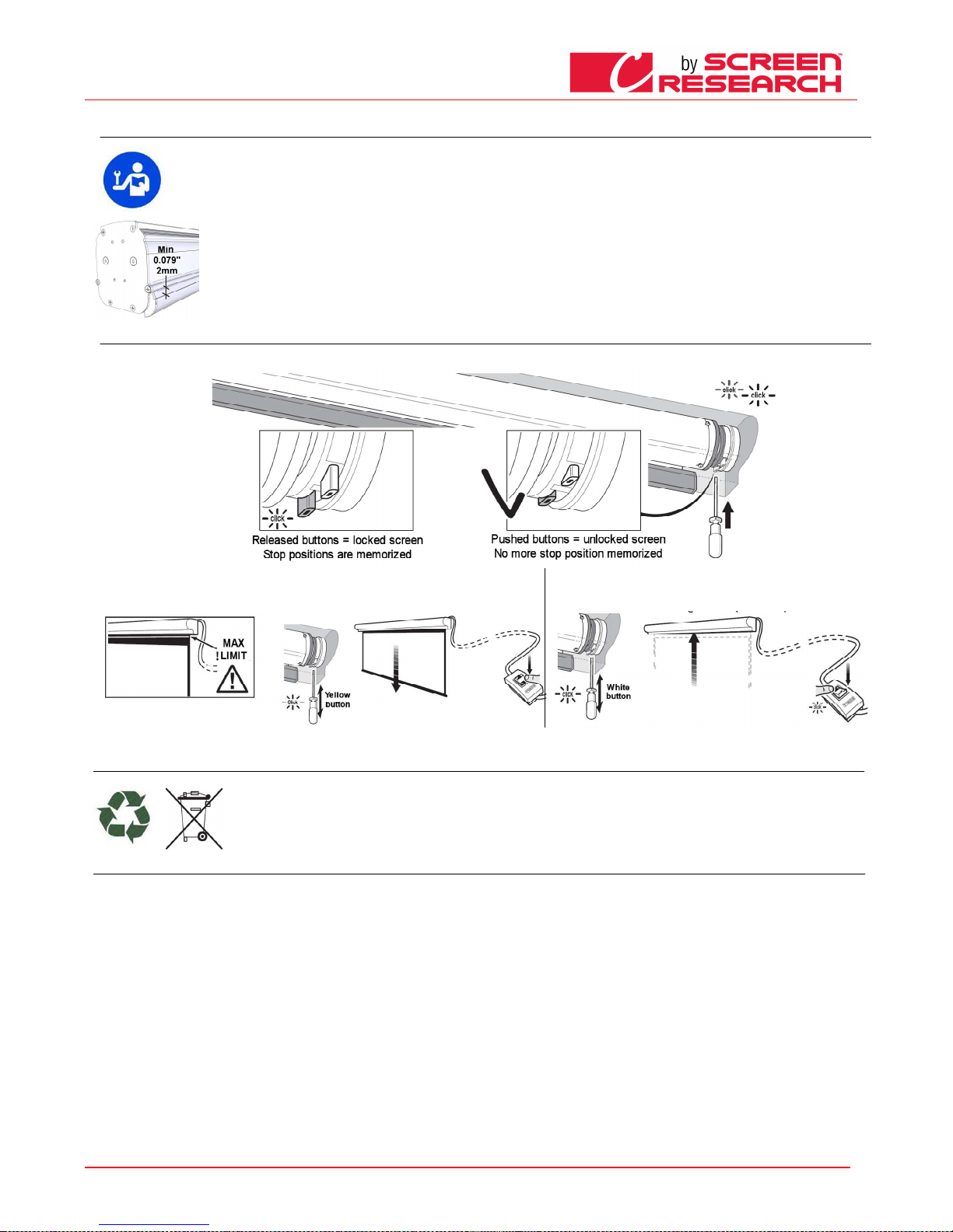
DEUTSCH - Betriebsanleitung Projektionswand
Made by Adeo Screen sp.
Z o.o. (Polska) Specifications a
re subject to change without notice. E&OE
Please verify that you are working with the latest revision of this document before specifying your screen.
Doc: Manual CLCTS-CLCLT rev5 | 03.02.2015| Download at: www.screenresearch.com 2015 AdeoSreen All Rights Reserved.
Page
17
10 EINSTELLUNG DES ENDSCHALTERS
10 EINSTELLUNG DES ENDSCHALTERS10 EINSTELLUNG DES ENDSCHALTERS
10 EINSTELLUNG DES ENDSCHALTERS
ACHTUNG, VOR DEM E INSTELLEN LESEN
ACHTUNG, VOR DEM E INSTELLEN LESENACHTUNG, VOR DEM E INSTELLEN LESEN
ACHTUNG, VOR DEM E INSTELLEN LESEN
Die angegebenen Eins tellungen dürfen nur von hierzu befugtem Fachpe rsonal vorgenommen werden. Durch die nicht korrekt e Ausführung der beschriebenen Vorgänge können
Beschädigungen des P rodukts verursacht werden; solche Schäden sind nicht von der Garantie gedeckt.
BITTE BEACHTEN
BITTE BEACHTENBITTE BEACHTEN
BITTE BEACHTEN
“DER OBERE ENDSCH ALTER IST IMMER AUF 2 mm VOM GEHÄUSE EINZUSTE LLEN “ – siehe Bild rechts.
Der Endschalter wird s o eingestellt, dass die Projektionsleinwand mindestens anderthalb Mal um die Rolle gewickelt werden kan n, um das Ablösen der Leinwand zu verhindern.
Zur Veränderung des S ichtbereichs können die Endschalter verstellt werden, w obei besonders vorsichtig vorzugehen ist. Durch di e fehlerhafte Einstellung des Endschalters kann
folgendes verursacht w erden:
- Ablösung der Leinwa nd von der Rolle
- Aufrollen der Projekt ionsleinwand in umgekehrter Richtung, wodurch die Ebe nheit der Projektionsfläche und die Wickelmechan ismen beschädigt werden.
- Zerstörung der Schwe ißnaht des unteren schwarzen Randes (umrandete Pro jektionswände).
- Überlastung des Moto rs mit möglicher Beschädigung und Auslösen des dari n enthaltenen Thermowiderstandes.
- Übermäßiges Aufwic keln des Endschalter-Justiersystems mit daraus f olgender Beschädigung der Mechanik.
GARANTIE
GARANTIEG ARANTIE
GARANTIE
Bei Aufbrechen der Sie gel und bei Schäden, die auf eine falsche Einstellung zu rückzuführen sind, werden die anfallenden Repara turen nicht als Garantiefall behandelt.
EINSTELLUNG DER ENDSCHALTER SOMFY
EINSTELLUNG DER ENDSCHALTER SOMFYEINSTELLUNG DER ENDSCHALTER SOMFY
EINSTELLUNG DER ENDSCHALTER SOMFY
- Die weiße und die gel be Taste drücken, um die gespeicherten Endschalte r freizugeben.
--Stellen Sie das Gewebe in der unteren Endlage, ACHTUNG nicht auf die Grenze in der Projektion Leinwand
angegeben überschreiten und lassen Sie den gelbe Knopf
- Stellen Sie das Gewebe in der unteren top, und lassen Sie den weißen K nopf
PRODUKTENTSORGUNG
PRODUKTENTSORGUNGPRODUKTENTSORGUNG
PRODUKTENTSORGUNG
Produkt gilt, gilt auch am Ende der Lebensd auer für seine Entsorgung: sie ist von Fachpersonal vorzunehmen.
Dieses Produkt besteht aus verschiedenen Material ien: einige können wieder verwertet werden, andere sind zu entsorgen. Holen Sie In formationen über das in Ihrem
Land geltende Recycling- und Entsorgungss ystem für diese Produktkategorie ein.
Wie Sie aus dem Symbol hier links ersehen können, ist es verboten, das Produkt in den Hausmüll zu geben. Befolgen Sie also die Vorga ben zur Mülltrennung nach den
in Ihrem Land geltenden Vorschriften oder geben Sie das Produkt beim Neukauf eines gleichwertigen Artikels an den Händler zurück.
ACHTUNG:
ACHTUNG:ACHTUNG:
ACHTUNG: die örtlichen Gesetze könne n schwere Strafen bei missbräuchlicher Entsorgung dieses Produkts vorsehen
GARAN
GARANGARAN
GARANTIE
TIETIE
TIE
1. GARANTIE
1. GARANTIE1. GA RANTIE
1. GARANTIE Die Firma ScreenResearch garantiert unter folgenden Bedingungen und mit folgenden Fristen, dass das von ihr gefertigte Produkt frei von Fabrikationsmängeln ist, die auf Material- und
Verarbeitungsfehler zurückzuführen sind. Für die Projektionsgewebe und Profile wird eine Garantie von fünf (5) Jahren ab Originalrechnung gewährt. Für Motoren, Motorsteuerungen, Fernbedienungen und
Montageteile wird eine Garantie von drei (3) Jahren ab Originalrechnung gewährt.
2. BEDINGUNGEN UND EINSCHRÄNK
2. BEDINGUNGEN UND EINSCHRÄNK2. BEDINGUNGEN UND EINSCHRÄNK
2. BEDINGUNGEN UND EINSCHRÄNKUNGEN
UNGENUNGEN
UNGEN Diese Garantie unterliegt den folgenden Bedingungen und Einschränkungen. Bei Benutzung oder Handhabung des Produkts unter Missachtung der im
Lieferumfang enthaltenen Anleitungen, bei missbräuchlicher oder zweckwidriger Verwendung, bei Beschädigung infolge eines Unfalls oder Nachlässigkeit während des Transports, oder wenn der Fehler auf
Reparaturen oder Eingriffe durch unbefugtes Personal zurückzuführen ist, ist die Garantie ungültig und nicht anwendbar. Das Produkt muss von einem von ScreenResearch befugten Fachmann installiert
werden und die im Benutzerhandbuch aufgeführten Wartungseingriffe sind regelmäßig durchzuführen.
3. RÜCKSENDUNGEN
3. RÜCKSENDUNGEN3. RÜCKSENDUNGEN
3. RÜCKSENDUNGEN Ohne schriftliche Genehmigung (RMA-Nummer) von ScreenResearch wird keine Warenrücksendung angenommen. Das Produkt muss in der Originalverpackung oder in einer
gleichwertigen Verpackung zurückgeschickt werden, um Transportschäden zu vermeiden. Verpackung und Rücksendung an ScreenResearch oder an eine Vertragswerkstatt gehen zu Lasten des Kunden. Die
Rückgabe nach Reparatur erfolgt auf Kosten von ScreenResearch. Dem zurückgeschickten Produkt muss eine schriftliche Beschreibung des Fehlers und eine Fotokopie des Original-Kaufbelegs beiliegen. Auf
diesem Beleg müssen Modell und Seriennummer, Kaufdatum, Name und Anschrift des Käufers und des Fachhändlers, sowie der vom Käufer bezahlte Preis klar und deutlich angegeben sein. ScreenResearch
behält sich das Recht vor, das Design jedes Produkts ohne jegliche Verpflichtung in Bezug auf vorher hergestellte Produkte zu überarbeiten und die Preise bzw. Leistungsmerkmale jedes Produkts ohne
Vorankündigung und ohne jegliche Verpflichtung gegenüber irgendeiner Person zu ändern.
4. ABHILFE
4. ABHILFE4. ABHILFE
4. ABHILFE Wenn das Produkt nicht der obigen Garantie entspricht, ist die einzige Abhilfe für den Käufer im Sinne der vorliegenden eingeschränkten Garantie die Rücksendung des Produkts an
ScreenResearch oder an eine Vertragswerkstatt. Die Nichtkonformität wird ohne Kosten für Arbeitszeit oder Ersatzteile beseitigt.
5. BESCHRÄNKUNG AUF DEN ERSTKÄUFER
5. BESCHRÄNKUNG AUF DEN ERSTKÄUFER 5. BESCHRÄNKUNG AUF DEN ERSTKÄUFER
5. BESCHRÄNKUNG AUF DEN ERSTKÄUFER Diese Garantie gilt ausschließlich für den Erstkäufer des garantierten Produkts und ist bei einem Weiterverkauf desselben nicht auf den Erwerber übertragbar.
6. VERSCHIEDENES
6. VERSCHIEDENES6. VERSCHIEDENES
6. VERSCHIEDENES Alle impliziten Garantieansprüche in Bezug auf die Produkte von ScreenResearch sind auf die Dauer dieser Garantie beschränkt. Die Garantie deckt keine dem Käufer eventuell
unmittelbar oder mittelbar entstandenen Schäden. Einige Staaten oder Länder erlauben keine Einschränkungen der Dauer eines impliziten Garantieanspruchs, noch den Ausschluss oder die Einschränkung
der Unfall- oder Folgeschäden, daher sind die obigen Einschränkungen oder Ausnahmen möglicherweise nicht anwendbar. Mit dieser Garantie werden spezifische rechtliche Ansprüche gewährt und unter
Umständen können auch andere Ansprüche vorliegen, die von Staat zu Staat bzw. von Land zu Land variieren.
7. ANFRAGEN
7. ANFRAGEN7. ANFRAGEN
7. ANFRAGEN in Bezug auf die obige eingeschränkte Garantie können an den Vertragshändler von ScreenResearch gerichtet werden.
8. ERBRINGEN DER GARANTIELEISTUNG DURCH VERTRAGSHÄNDLER
8. ERBRINGEN DER GARANTIELEISTUNG DURCH VERTRAGSHÄNDLER8. ERBRINGEN DER GARANTIELEISTUNG DURCH VERTRAGSHÄNDLER
8. ERBRINGEN DER GARANTIELEISTUNG DURCH VERTRAGSHÄNDLER Die Firma ScreenResearch hat den Vertrieb ihrer Produkte in vielen Ländern weltweit autorisiert. In jedem Land ist der
Vertragshändler/Importeur für die Ausführung der Garantieeingriffe an den im jeweiligen Land verkauften Produkten verantwortlich. Die Garantieleistung muss beim Importeur, bzw. bei dem Händler, bei dem
das Produkt erworben wurde, angefordert werden
Page 18
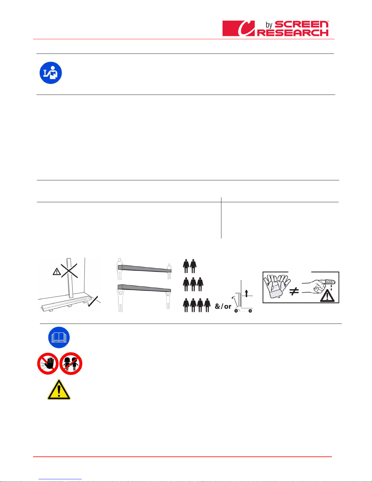
ESPANOL - Manual de uso de la pantalla
Made by Adeo Screen sp.
Z o.o. (Polska) Specifications a
re subject to change without notice. E&OE
Please verify that you are working with the latest revision of this document before specifying your screen.
Doc: Manual CLCTS-CLCLT rev5 | 03.02.2015| Download at: www.screenresearch.com 2015 AdeoSreen All Rights Reserved.
Page
18
01
01 01
01 INTRODU
INTRODUINTRODU
INTRODUCCI
CCICCI
CCIÓÓÓÓNNNN
El presente manual forma parte integrante del producto y su lectura y comprensión revisten importancia fundamental para la seguridad. En el manual se indican las normas y modos de
empleo para que el cliente utilice la pantal la correctamente y con seguridad. El manual deberá acompañar siempre al producto y debe rá ser guardado en un lugar que garantice su
integridad y que esté al alcance de las pers onas autorizadas a consultarlo. Cada usuario del producto será responsable de la c orrecta conservación del manual. El usuario también es
responsable de controlar la funcionalid ad de la pantalla y de la reparación o sustitución de piezas sujetas a desgaste que podrían proc urar daños.
Las imágenes contenidas en este manual t ienen la finalidad de describir en detalle las funciones, características o procedimientos. Sin embargo, pueden diferir por el tipo de modelo
representado, lo que no implica cambios en el significado descriptivo de la imagen.
02 CARACTERĺSTICAS GENERALES DEL PRODUCTO
02 CARACTERĺSTICAS GENERALES DEL PRODUCTO02 CARACTERĺSTICAS GENERALES DEL PRODUCTO
02 CARACTERĺSTICAS GENERALES DEL PRODUCTO
Las pantallas se fabrican de conformidad con las disposiciones de las siguientes directivas CE: 2006-95-CE LDV
2004-108-CE EMC
1999-05-CE R&TTE
2005-32-CE Eco design
2011-65-CE ROHS
2002-96-CE RAEE
2001-95-CE SEGURIDAD
La pantalla que se describe en este m anual tiene que utilizarse exclusivamente como soporte para la proyección de vídeo. Cualquier uso no contemplado en este manual, no está permitido.
La pantalla dispone de una o más tela s de proyección en PVC plastificado sin cadmio o en FIBRA de VIDRIO impregnada con PVC plastificad o, y cada tela se puede clasificar en la categoría:
- M1 o M2 de a cuerdo con las normas francesas (LNE Labora toire national de métrologie et d’essais – SME Centre de recherches du Bouchet -
WARRINGTONFIRE GENT La boratoire de métrologie
et d’essais – IFTH Laboratoire accreditè )
- B1 o B2 de acue rdo con las normas alemanas (LNE Laboratoire national d e métrologie et d’essais – SME Centre de recher ches du Bouchet - WARRINGTONFIRE GENT Labor
atoire national de
métrologie et d’essais)
- UL94HB de acuerdo con las normas de los EE.UU. (THE GOVMARK Organization, Inc.)
Puesto que aún no existe en Europ a una armonización entre las diferentes normativas nacionales de clasificación , se precisa que la clase M1 francesa corresponde a material no inflamable y la clase
M2
corresponde a material difícilmente inf lamable.
03 DESEMBALAJE DE LA PANTALLA Y DESPLAZAMIENTO DEL PRODUCTO
03 DESEMBALAJE DE LA PANTALLA Y DESPLAZAMIENTO DEL PRODUCTO 03 DESEMBALAJE DE LA PANTALLA Y DESPLAZAMIENTO DEL PRODUCTO
03 DESEMBALAJE DE LA PANTALLA Y DESPLAZAMIENTO DEL PRODUCTO
Controle que ninguna parte de la pantalla haya sufrido desperfectos durante el transporte. En caso de anomalías, informe de inmediato al revendedor. Controle que estén presentes todos los accesorios
para el tipo de pantalla descrito en el manual.
Pantalla enrollable motorizada o con control radio integrado
Pantalla enrollable motorizada o con control radio integradoPantalla enrollable motorizada o con control radio integrado
Pantalla enrollable motorizada o con control radio integrado
Pantalla enrollable con manivela
Pantalla enrollable con manivelaPantalla enrollable con manivela
Pantalla enrollable con manivela
-
2 Kits de soportes para la instalación (para pantallas de hasta 3 m de ancho)
-3 Kits de soportes para la instalación (para pantallas de más de 3 m de ancho)
-2 Soportes laterales (para pantallas sin carcasa)
-1 interruptor unipolar 10°, 250V “hombre presente”, con flechas direccionales, incluida caja para el montaje en la pared
-1 transmisor radio frecuencia (para pantallas versión radio integrado)
-1 llave hexagonal de plástico
-1 manual de instrucciones
(no se incluyen ni tornillos ni tacos para la pared)
-
2 Kits de soportes para la instalación (para pantallas de hasta 3m de ancho)
-3 Kits de soportes para la instalación (para pantallas de más de 3m de
ancho)
-1 varilla de mando
-1 manual de instrucciones
(no se incluyen ni tornillos ni tacos para la pared)
ATENCIÓN
ATENCIÓNATENCIÓN
ATENCIÓN no utilizar ni una cuchilla ni un objeto puntiagudo para abrir el embalaje, utilizar siempre guantes de protección durante la apertura del embalaje y la instalación o desplazamiento del producto.
Desplazar e instalar el producto mínimo entre dos, tres o cuatro personas, según el peso del producto (valores de referencia de carga por persona: 25kg macho - 15kg hembra). En caso de pesos superiores
se recomienda utilizar equipos de elevación específicos.
04 NORMAS GENERALES DE SEGURIDAD
04 NORMAS GENERALES DE SEGURIDAD 04 NORMAS GENERALES DE SEGURIDAD
04 NORMAS GENERALES DE SEGURIDAD
Lea detenidamente y comprenda bien las instrucciones y advertencias que contiene este manual antes de comenzar a utilizar el producto y antes de llevar a cabo intervenciones
de mantenimiento. Está prohibido terminantemente de instalar la pantalla sobre àreas de posible trànsito de personas.
Antes y durante el uso controle que la pantalla no genere situaciones de peligro.
No altere, quite o deteriore ningún elemento o parte de la pantalla.
No lleve nunca a cabo operaciones de mantenimiento en la pantalla con el motor encendido (para mayor seguridad se recomienda desconectarlo de la alimentación).
Está prohibido terminantemente a los niños utilizar el producto. Está terminantemente prohibido dejar que los niños se acerquen a la pantalla durante su movimiento.
Todas las pantallas están garantizadas y la validez de la garantía depende del respeto efectivo y del cumplimiento de las instrucciones que contiene este manual.
ATENCIÓN:::: el kit de instalación de la pantalla no dispone de tornillos y tacos de expansión para la fijación a las paredes/ techos. El instalador es responsable de la elección
adecuada de los tornillos y de los sistemas de fijación, de acuerdo con los diferentes tipos de material de las paredes o techos en los que tiene que instalar la pantalla. Una
instalación incorrecta podría comprometer la seguridad de las personas que utilizarán el producto, el fabricante no es responsable de daños a bienes o personas provocados por
una instalación incorrecta, un uso inadecuado de la pantalla o un mantenimiento escaso o insuficiente.
El fabricante no es responsable de problemas vinculados con errores de instalación En caso de necesidad, póngase en contacto con nuestro departamento técnico para obtener
más aclaraciones.
La instalación de la pantalla, las conexiones eléctricas y las comprobaciones en caso de fallo del enrollamiento motorizado tiene que efectuarlos el distribuidor autorizado o
personal competente y que conozca los riesgos que puede representar la energía eléctrica. El cable de conexión no se puede sustituir. Si el cable se deteriora será necesario
sustituir la pantalla. La alteración del final de recorrido o la perforación del sello situado encima de los agujeros provoca la anulación de la garantía.
AL CONCLUIR EL MONTAJE DE LA PANTALLA EN LOS SOPORTES ES OBLIGATORIO COMPROBAR QUE ESTÉ PERFECTAMENTE HORIZONTAL ANTES DE UTILIZARLA
Page 19
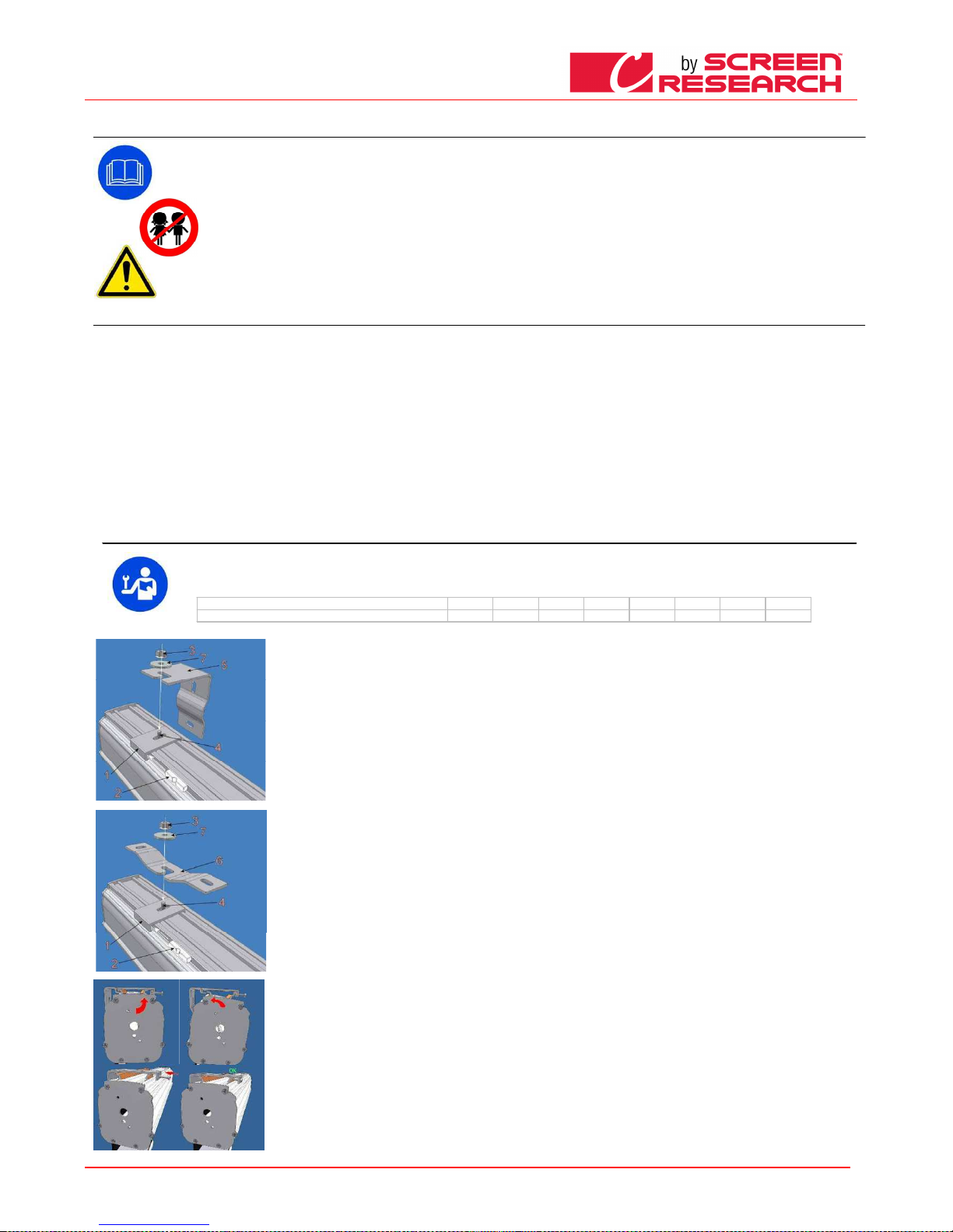
ESPANOL - Manual de uso de la pantalla
Made by Adeo Screen sp.
Z o.o. (Polska) Specifications a
re subject to change without notice. E&OE
Please verify that you are working with the latest revision of this document before specifying your screen.
Doc: Manual CLCTS-CLCLT rev5 | 03.02.2015| Download at: www.screenresearch.com 2015 AdeoSreen All Rights Reserved.
Page
19
05
05 05
05 ADVERTENCIAS Y PRECAUCIONES PARA EL USO
ADVERTENCIAS Y PRECAUCIONES PARA EL USOADVERTENCIAS Y PRECAUCIONES PARA EL USO
ADVERTENCIAS Y PRECAUCIONES PARA EL USO
Las pantallas están destinadas para su utilización en interiores con temperatura (20 - 25 °C) y humedad normales. Deberán tomarse precauciones particulares para su
utilización en exteriores, sobre todo con relación a las condiciones de temperatura y polvo. La exp osición a temperaturas superiores a 50 °C podría provocar deformaciones
permanentes de la planeidad de la tela, o la separación de la tela del tubo de enrollamiento.
No deje la tela de proyección expuesta durante períodos largos a la luz solar para evitar que se amarillee (también controle que a causa de la exposición a la luz solar la
pantalla no alcance los niveles de temperatura antedichos).
Ya que el material del que está hecha la tela de proyección (PVC) tiende a cargarse electrostáticamente, el exceso de polvo en el ambiente de proyección puede provocar un
degrado de las cualidades ópticas de la tela a causa del depósito de polvo por atracción electrostática (véase también limpieza de la tela de proyección).
ATENCIÓN
ATENCIÓNATENCIÓN
ATENCIÓN: no fuerce manualmente la salida de la tela, porque podría averiar el motor o desprender la carcasa de contención de los soportes de fijación.
No permita que los niños jueguen con los dispositivos de mando fijos. Mantenga los mandos a distancia fuera del alcance de los niños.
Controle la pantalla mientras está subiendo y mantenga a las personas alejadas hasta que la pantalla no esté completamente cerrada.
Está prohibido bloquear, impedir y forzar el movimiento de la pantalla, asirse o colgarse, añadir o aplicar cualquier objeto en la tela o remarco y modificar la estructura de la
pantalla, puesto que podría provocar problemas al sistema de enrollamiento con daños consiguientes a bienes o personas.
06
06 06
06 NETTOYAGE ET ENTRETIEN
NETTOYAGE ET ENTRETIENNETTOYAGE ET ENTRETIEN
NETTOYAGE ET ENTRETIEN
L’écran et les toiles de projection des écrans sont délicats : il faut dont prêter une attention particulière et suivre les instructions suivan tes pour le nettoyage.
Ne jamais utiliser de so lvants, produits chimiques ou abrasifs, ni d’outil s pointus pour nettoyer la surface.
Éviter tout contact avec d’autres matériaux (peintures, encres, etc.) car il pou rrait être impossible de les éliminer de la surface de la toile.
TOILES DE PROJECTI ON CLEARPIX:
TOILES DE PROJECTI ON CLEARPIX: TOILES DE PROJE CTION CLEARPIX:
TOILES DE PROJECTI ON CLEARPIX: utiliser un chiffon doux, propre et hu midifié en effectuant toujours des mouvements partant du c entre de la zone de projection pour aller vers les b ords. Il n’est permis
d’utiliser une brosse mo ntée sur un aspirateur que si les poils sont doux et parfaitement propres.
TOILES DE PROJECTI ON
TOILES DE PROJECTI ONTOILES DE PROJECTION
TOILES DE PROJECTI ON
SOLIDPIX, MULT IPIX,
SOLIDPIX, MULTIPIX,SOL IDPIX, MULTIPIX,
SOLIDPIX, MULTIPIX, : Pour nettoyer la toile de projection, utiliser un chiffon doux, propre, hum idifié, avec un détergent à base neutre ou de l’alcool si nécessaire. Étant donné
qu’après le nettoyage la toile pourrait se charger d’électricité statique à cause du frottement du chiffon, il est conseillé de passer, ave c un chiffon propre, un liquide antistatique sur la toile a fin d’éviter que la
poussière ne soit à nouv eau attirée par l’écran.
TOILES DE PROJECTI ON SILVEPIX
TOILES DE PROJECTI ON SILVEPIX TOILES DE PROJECTI ON SILVEPIX
TOILES DE PROJECTI ON SILVEPIX est obligatoire de lire les instr uctions fournies en écran tissu
PROFILS
PROFILSPROFILS
PROFILS:
::
: Pour nettoyer le caisso n, utiliser un chiffon doux propre et un détergent non agressif si nécessaire.
PROFILS VELOUTÉS
PROFILS VELOUTÉSPR OFILS VELOUTÉS
PROFILS VELOUTÉS :
: :
: Pour nettoyer le profil, dépou ssiérer en utilisant un chiffon doux et propre, ou bien u ne brosse à poils doux et antistatiques. Il n’est pe rmis d’utiliser une brosse montée sur un aspirateur
que si les poils sont dou x et parfaitement propres.
STRUCTURE ET BRIDES DE FIXATION
STRUCTURE ET BRIDES DE FIXATIONSTRUCTURE ET BRIDES DE FIXATION
STRUCTURE ET BRIDES DE FIXATION :
: :
: Il est obligatoire de vérifier régul ièrement l’état du produit et la tenue des brides de fix ation. En cas de déformations, lacérations ou de flé chissements structurels des
brides, vis et autres élémen ts qui composent le produit, il est obligatoire de m ettre immédiatement en sécurité la zone où l’écran est installé, afin d’éviter tout type de dommage aux choses ou aux personnes.
Ensuite, il est obligatoire de procéder à la substitution immédiate du composa nt défectueux et à la réparation du produit.
07
07 07
07 INSTRUCCIONES PARA LA INSTALACIÓN
INSTRUCCIONES PARA LA INSTALACIÓN INSTRUCCIONES PARA LA INSTALACIÓN
INSTRUCCIONES PARA LA INSTALACIÓN
ATENCIÓN:
ATENCIÓN:ATENCIÓN:
ATENCIÓN: Es 's absolutamente proh ibido la instalación de la pantalla en las paredes móviles o cables inestables, los soportes deben ser aplicado sobre superficies que garanticen en
el tiempo la distancia. La pantal la se deberá instalar utilizando tornillos y tacos adecuados para el peso y el tipo de pared o techo sobre los que se fijarán los soportes, antes de
comenzar la instalación escoja el tipo de taco o fijación de acuerdo con el siguiente esquema:
Pantalla c
Pantalla cPantalla c
Pantalla c
on ancho hasta cm
on ancho hasta cmon ancho hasta cm
on ancho hasta cm
160
160160
160
200
200200
200
250
250250
250
300
300300
300
360
360360
360
410
410410
410
520
520520
520
620
620620
620
Peso total a considerar
Peso total a considerarPeso total a considerar
Peso total a considerar
Kg 20
Kg 20Kg 20
Kg 20
Kg 25
Kg 25Kg 25
Kg 25
Kg 30
Kg 30Kg 30
Kg 30
Kg 35
Kg 35Kg 35
Kg 35
Kg 45
Kg 45Kg 45
Kg 45
Kg 50
Kg 50Kg 50
Kg 50
Kg 100
Kg 100Kg 100
Kg 100
Kg 150
Kg 150Kg 150
Kg 150
INSTALACIÓN EN LA PARED:
INSTALACIÓN EN LA PARED:I NSTALACIÓN EN LA PARED:
INSTALACIÓN EN LA PARED:
Coloque el tornillo 4 con la rosca vuelta ha cia arriba en la placa 1 y enrosque un poco la tuerca 3 dejando 4-5 mm de huelgo; enganche la placa 1 en la
carcasa e introduzca un pasador de plástico 2 en la cavidad del soporte. Cabe señalar que, sólo en relación al montaje, es indiferente si se monta la placa en
una dirección o en la otra, puesto que los pe rfiles de enganche de la carcasa son perfectamente simétricos. Fije en la pared el soporte 5 co n tacos de
expansión adecuados para el tipo de p ared (mínimo Ø 8 mm), y fije la placa 1 con el soporte 5 utilizando la arandela 7 y el perno 3.
INSTALACI
INSTALACIINSTALACI
INSTALACIÓN EN E L TECHO:
ÓN EN EL TECHO: ÓN EN EL TECHO:
ÓN EN EL TECHO:
fije los soportes 6, entregados de serie con la pantalla, en el techo utilizando tacos de expansión adecuados para el tipo de techo (mínimo Ø 8 mm), a unos
10 - 15 cm del extremo de la carcasa. Par a las pantallas de ancho superior a 350 cm, el tercer soporte se coloca en el centro de la carcasa . Ponga el tornillo
4 con la rosca vuelta hacia arriba en la pla ca 1 y enrosque un poco la tuerca 3 dejando 4-5 mm de huelgo; enganche la placa 1 en la carcasa e introduzca un
pasador de plástico 1 en la cavidad de l soporte. Fije la placa 1 con el soporte 6 utilizando la arandela 7 y el perno 3.
instalación en el techo directamente con las placas de fijación:
Es posible instalar en el techo directamente las placas de enganche 1 si usted quiere que la carcasa quede lo más pegada posible al techo ( atención: para
que dicha instalación sea fácil y rápida es necesaria una perfecta planeidad del techo y una alineación perfecta de las placas). Fije las placa s con tacos de
expansión adecuados para el tipo de p ared (mínimo Ø 8 mm), a unos 10 -15 cm del extremo de la carcasa. Para este tipo de montaje e l lado de la placa para
el pasador de fijación, por lo general, queda dirigido hacia el lado delantero de la car casa para facilitar la introducción del pasador. Controle la perfecta
alineación y horizontalidad de las placas. A tal fin se pueden utilizar distanciadores, c omo las arandelas metálicas incluidas en el embalaje. Ponga atención
porque la precisión de tal operación es la que determina la velocidad y la facilidad de enganche de la carcasa a la placa. Para las pantallas de anch o superior
a 350 cm la tercera placa se coloca en el cent ro de la carcasa. Coloque la carcasa en las placas con un movimiento semigiratorio (enganche automático) e
introduzca el pasador de plástico que asegu ra la fijación de la carcasa a las placas.
INSTALACIÓN CON SISTEMA RAPID O
INSTALACIÓN CON SISTEMA RAPID OINSTALACIÓN CON SISTEMA RA PIDO
INSTALACIÓN CON SISTEMA RAPID O
1) fije con tacos de expansión adecuados ( mínimo Ø 8 mm) el soporte (es posible la fijación en el techo o en la pared) controlando su nivelación;
2) fije la pantalla en los soportes de acuerd o con la fig.7;
Page 20
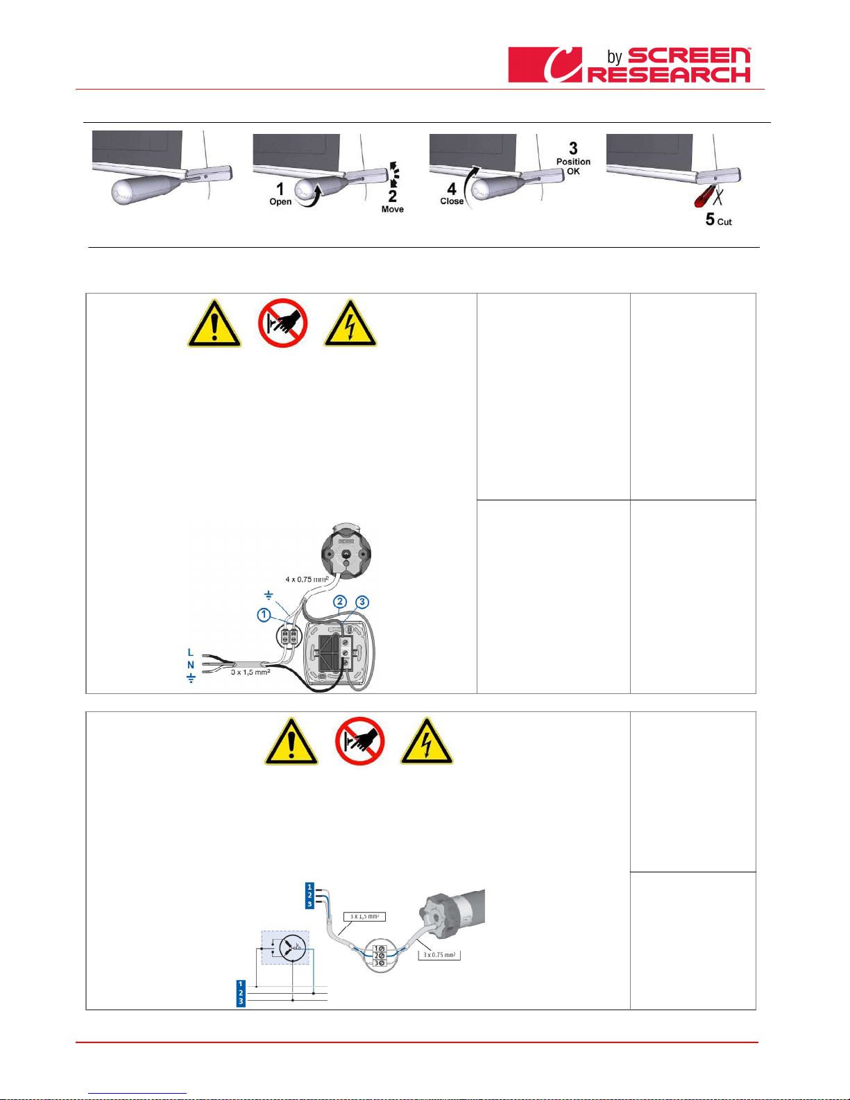
ESPANOL - Manual de uso de la pantalla
Made by Adeo Screen sp.
Z o.o. (Polska) Specifications a
re subject to change without notice. E&OE
Please verify that you are working with the latest revision of this document before specifying your screen.
Doc: Manual CLCTS-CLCLT rev5 | 03.02.2015| Download at: www.screenresearch.com 2015 AdeoSreen All Rights Reserved.
Page
20
08
08 08
08 REG
REGREG
REGULACION DE CONTRAPESO DE TENSIONAMENTO
ULACION DE CONTRAPESO DE TENSIONAMENTOULACION DE CONTRAPESO DE TENSIONAMENTO
ULACION DE CONTRAPESO DE TENSIONAMENTO
09 IDENTIFICACIÓN DEL TIPO DE MOTOR
09 IDENTIFICACIÓN DEL TIPO DE MOTOR 09 IDENTIFICACIÓN DEL TIPO DE MOTOR
09 IDENTIFICACIÓN DEL TIPO DE MOTOR ––––
CARACTERÍSTICAS
CARACTERÍSTICAS CARACTERÍSTICAS
CARACTERÍSTICAS –––– CONEXIÓN ELÉCTRICA
CONEXIÓN ELÉCTRICA CONEXIÓN ELÉCTRICA
CONEXIÓN ELÉCTRICA
El tipo de motor instalado en el producto se identifica en la etiqueta en la que aparece el logo CE y que se aplica en todos los productos; al abrir el embalaje se recomienda controlar esta etiqueta e
identificar el modelo correcto de motor para efectuar una instalación y un cableado correctos. Si la potencia del motor no corresponde a la potencia de la línea eléctrica del lugar de instalación, tendrá que
ponerse en contacto con un técnico electricista y utilizar un adecuado transformador de corriente y Hz.
CONEXIÓN ELÉCTRICA:
CONEXIÓN ELÉCTRICA:CONEXIÓN ELÉCTRICA:
CONEXIÓN ELÉCTRICA:
el cableado eléctrico tiene que respetar las normas CEI en vigor. La norma CEI EN 60335-1 prevé que la red de
alimentación cuente con un dispositivo de desconexión omnipolar con una distancia de apertura de los contactos de
por lo menos 3 mm. Para accionar la pantalla utilice sólo el interruptor que se entrega de serie, o un modelo
equivalente, siguiendo las indicaciones del esquema de conexión de la Fig. 4 (si el motor está montado a la izquierda
los colores de los cables se tendrán que invertir, es decir bajada = marrón, subida = negro). El interruptor tiene que
estar instalado a la vista del producto y a una altura comprendida entre 1,5 y 1,8 m de altura del suelo.
Para conectar los cables al interruptor que se entrega de serie, saque las placas frontales para acceder a los botones
de bloqueo/desbloqueo
ATENCIÓN:
ATENCIÓN: ATENCIÓN:
ATENCIÓN:
La ejecución correcta de las conexiones eléctricas, con todas las de la ley y respetando las normas vigentes, es
importante para prevenir accidentes y para un funcionamiento apropiado y duradero de la pantalla.
Antes de efectuar una operación sobre las partes eléctricas, controle que no haya tensión.
En las pantallas con carcasa, el motor está situado a la derecha de la pantalla vista de frente (si se solicita, podemos
montarlo a la izquierda). No conecte nunca dos o varios motores al mismo interruptor sin un mando para grupo, o dos
interruptores al mismo motor.
Somfy
Somfy Somfy
Somfy 230V 50Hz
230V 50Hz230V 50Hz
230V 50Hz
Carac
CaracCarac
Características del motor
terísticas del motorterísticas del motor
terísticas del motor
Frecuencia: ~Hz50
Potencia: 90W
Par: 6Nm
Velocidad: 12Rpm
N° máximo de ciclos: 2
Longitud del cable: 2.5m
Resistencia mecánica:
de acuerdo con la norma EN14202
T° de funcionamiento:
entre –20 y +55 °C
Conexión para cada motor:
Conexión para cada motor:Conexión para cada motor:
Conexión para cada motor:
Azul (Comùn)
Marron (Subida)
Negro (Bajada)
Amarillo verde (Tierra 230V)
Somfy
Somfy Somfy
Somfy 120V 60Hz
120V 60Hz120V 60Hz
120V 60Hz
Características del motor
Características del motorCaracter ísticas del motor
Características del motor
Frecuencia: ~Hz60
Potencia: 80W
Par: 88in.lb
Velocidad: 14r/min
N° máximo de ciclos: 2
Longitud del cable: 2.5m
Resistencia mecánica:
de acuerdo con la norma EN14202
T° de funcionamiento:
entre –20 y +55 °C
Conexión para cada motor:
Conexión para cada motor:Conexión para cada motor:
Conexión para cada motor:
Blanco(Comùn)
Negro (Bajada)
Rojo (Subida)
Amarillo verde (Tierra 120V)
CONEXIÓN ELÉCTRICA:
CONEXIÓN ELÉCTRICA:CONEXIÓN ELÉCTRICA:
CONEXIÓN ELÉCTRICA:
el cableado eléctrico tiene que respetar las normas CEI en vigor. La norma CEI EN 60335-1 prevé que la red de alimentación disponga de un dispositivo de
desconexión omnipolar con una distancia de apertura de los contactos de por lo menos 3 mm por cada uno de los motores (por ej. clavija de enchufe, etc.) En caso
de necesidad, este dispositivo garantiza una desconexión rápida y segura de la corriente eléctrica.
Utilizar los cables para la conexión tal como se describe en la imagen.
ATENCIÓN:
ATENCIÓN:ATENCIÓN:
ATENCIÓN:
La ejecución correcta de las conexiones eléctricas, con todas las de la ley y respetando las normas vigentes, es importante para prevenir accidentes y para un
funcionamiento apropiado y duradero de la pantalla.
Antes de efectuar una operación sobre las partes eléctricas, controle que no haya tensión.
El motor en las pantallas que disponen de carcasa se encuentra a la derecha de la pantalla vista de frente
La pantalla se acciona mediante un mando a distancia que se entrega de serie.
Somfy RTS 230V 50Hz
Somfy RTS 230V 50HzSomfy RTS 230V 50Hz
Somfy RTS 230V 50Hz
Características del motor
Características del motorCaracterísticas del motor
Características del motor
Frecuencia: ~Hz50
Potencia: 120W
Par: 10Nm
Velocidad: 17Rpm
N° máximo de ciclos: 2
Longitud del cable: 3m
T° de funcionamiento: entre –20 y
+55 °C
Frecuencia: 433.92 MHz
Alcance transm: 150m
Conexión para cada motor:
Conexión para cada motor:Conexión para cada motor:
Conexión para cada motor:
Marrón (Fase 230V)
Azul (neutro)
Amarillo-Verde (Tierra)
Page 21
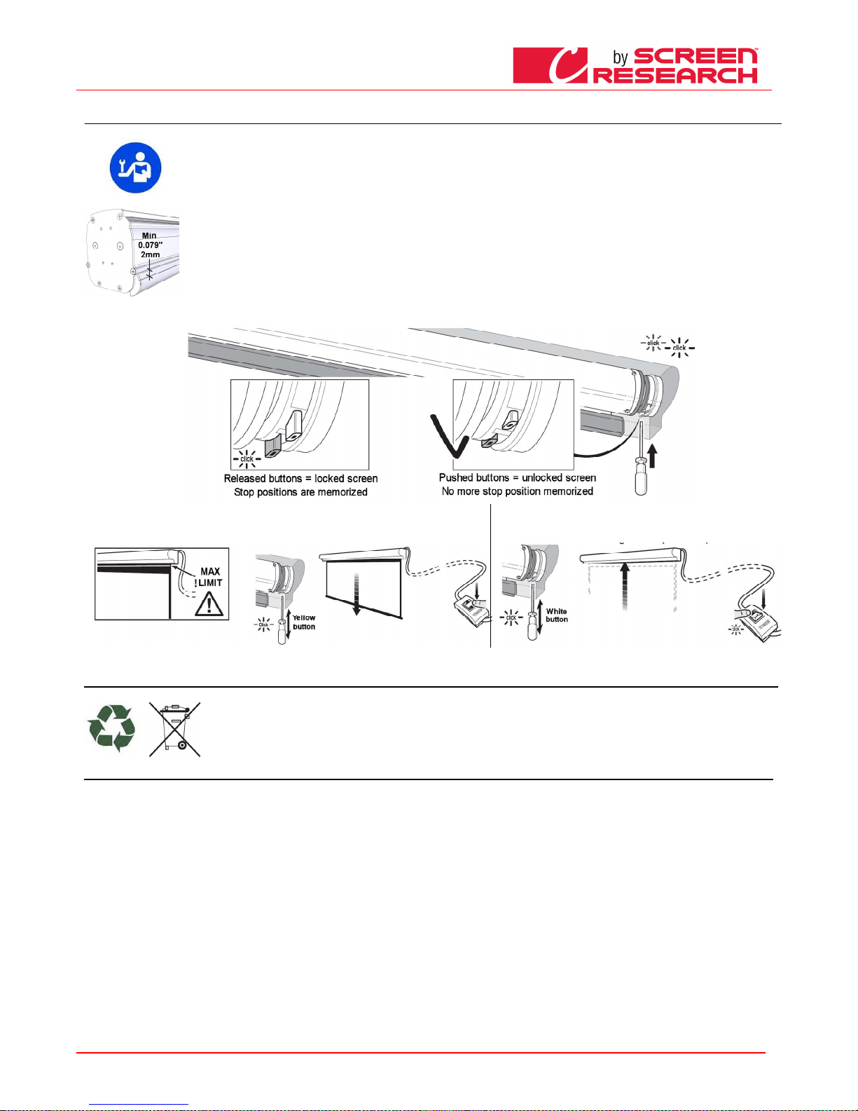
ESPANOL - Manual de uso de la pantalla
Made by Adeo Screen sp.
Z o.o. (Polska) Specifications a
re subject to change without notice. E&OE
Please verify that you are working with the latest revision of this document before specifying your screen.
Doc: Manual CLCTS-CLCLT rev5 | 03.02.2015| Download at: www.screenresearch.com 2015 AdeoSreen All Rights Reserved.
Page
21
10
10 10
10 REGULACION DE LOS FINALES DE CARRERA
REGULACION DE LOS FINALES DE CARRERAREGULACION DE LOS FINALES DE CARRERA
REGULACION DE LOS FINALES DE CARRERA
ATENCIÓN LEA DETE NIDAMENTE ANTES DE HACER LAS REGULACIO NES
ATENCIÓN LEA DETE NIDAMENTE ANTES DE HACER LAS REGULACIO NESATENCIÓN LEA DETE NIDAMENTE ANTES DE HACER LAS REGULACIO NES
ATENCIÓN LEA DETE NIDAMENTE ANTES DE HACER LAS REGULACIO NES
las regulaciones indicad as deberán ser hechas sólo por personal autor izado y experto, la ejecución incorrecta de los procedimiento s descritos puede causar daños al producto
que no serán reconocid os por la garantía.
ADVERTENCIAS
ADVERTENCIASADVE RTENCIAS
ADVERTENCIAS
“EL FINAL DE CARRERA SUPERIOR SIEMPRE DEBE SER REGULADO A 2mm D E LA CARCASA” véase imagen de la derecha.
El final de carrera está regulado en modo de permitir que la tela de proyecció n quede enrollada al menos 1,5 vueltas alrededor del tu bo para que no se desprenda. Ponga
mucha atención en el c aso en que la regulación de los finales de carrera debi era permitir desenrollar la tela de proyección más allá d e la configuración de fábrica. Una
regulación incorrecta de los finales de carrera podría causar:
-El desprendimiento de la tela de proyección del tubo
-El enrollamiento en sen tido contrario de la tela de proyección, perjudicando la planeidad de la superficie de proyección y de los mec anismos de enrollamiento.
-La rotura de la soldadu ra del borde negro inferior (pantallas con bordes).
-Un esfuerzo excesivo e n el motor con posible avería y activación de la resiste ncia térmica montada en el mismo.
-Un enrollamiento exce sivo del sistema de regulación del final de carrera con consiguiente rotura de la parte mecánica.
GARANTÍA
GARANTÍAGARAN TÍA
GARANTÍA
Se recuerda a los opera dores que en caso de alteración de los precintos y da ños derivados de una regulación incorrecta, las reparaci ones no estarán cubiertas por la garantía.
- Apretó los botones bla nco y amarillo para desbloquear las posiciones de parada final.
- Mueva la tela de proyección en la posición final hacia abajo, ATENCION n o exceda el límite especificado en el
lienzo de proyección y suelte el botón amarillo
- Mueva la tela de proyección en la posición final hacia superior, y suelte e l
botón blanco
ELIMINACION DEL PRODUCTO
ELIMINACION DEL PRODUCTOELIMINACION DEL PRODUCTO
ELIMINACION DEL PRODUCTO
Así como para los trabajos de instalaci ón, también al final de la vida útil de este producto, el desguace deberá ser hecho por personal experto.
Este producto está formado de varios tipos de materiales: algunos pueden ser reciclados, otros deberán ser eliminados. Infórm ese sobre los sistemas de reciclaje o
eliminación previstos por las normas vigent es en su territorio para esta categoría de producto.
El símbolo de al lado indica que está p rohibido desechar este producto con los residuos domésticos. Por lo tanto, haga la “rec ogida selectiva” según los métodos
previstos por las normas vigentes en su territorio, o bien entregue el producto al vendedor en el momento de la compra de un producto nuevo equivalente.
Atención: las normas locales pueden preve r sanciones pesadas en caso de eliminación abusiva de este producto.
GARANTIE
GARANTIEGARANTIE
GARANTIE
1.GARANTIE
1.GARANTIE1.GARANTIE
1.GARANTIE ScreenResearch garantit que le produit fabriqué est exempt de tout défaut de fabrication dans les matériaux et dans les usinages, conformément aux termes et conditions ci-après. Les toiles de
projection et les profils sont garantis pour une période de cinq (5) ans à compter de la date de la facture originale. Moteurs, commandes moteur, télécommandes, et matéri
el de montage sont garantis trois (3)
ans à compter de la date de la facture originale.
2.CONDITIONS ET LIMITATIONS
2.CONDITIONS ET LIMITATIONS2.CONDITIONS ET LIMITATIONS
2.CONDITIONS ET LIMITATIONS La présente garantie est soumise aux conditions et limitations suivantes. La garantie est nulle et inapplicable si le produit a été utilisé ou manipulé de manière non conforme
au manuel d’instructions contenu dans l’emballage du produit, s’il est mal utilisé ou utilisé de manière impropre, s’il a été endommagé par accident ou par négligence pendant le transport, ou si le défaut est
dû à des réparations ou modifications effectuées par un personnel non autorisé. Le produit doit être installé par un professionnel dûment autorisé par ScreenResearch et les opérations d’entretien indiquées
dans le manuel doivent être exécutées régulièrement.
3.RETOURS DE MARCHANDISE
3.RETOURS DE MARCHANDISE3.RETOURS DE MARCHANDISE
3.RETOURS DE MARCHANDISE Aucun produit restitué ne sera accepté sans autorisation écrite (RMA) de la part de ScreenResearch. Le produit doit être retourné emballé dans son emballage original ou
équivalent, afin d’éviter tout endommagement pendant le transport. Le produit doit être emballé et restitué à ScreenResearch ou à un centre de réparation autorisé, à la charge du client. Les frais de
restitution du produit sont à la charge de ScreenResearch. Le produit restitué doit être accompagné d’une description écrite du défaut et d’une photocopie du reçu original d’achat. Ce reçu doit indiquer
clairement la liste des modèles et le numéro de série, la date d’achat, le nom et l'adresse de l'acheteur et du revendeur autorisé, et le prix payé par l'acheteur. ScreenResearch se réserve le droit de modifier
le design de tout produit, sans aucune obligation par rapport aux produits fabriqués précédemment, et de modifier les prix ou les spécifications de tout produit sans préavis ou obligation d’aucune sorte.
4.SOLUTIONS
4.SOLUTIONS4.SOLUTIONS
4.SOLUTIONS Au cas où le produit ne serait pas conforme à la garantie ci-dessus, l'unique solution pour l’acheteur selon les dispositions de la présente Garantie Limitée est de restituer le produit à
ScreenResearch ou à un centre de recherche autorisé. La non-conformité sera rectifiée sans frais de main d’œuvre ni frais de substitution des composants.
5.LIMITE AU PREMIER ACHETEUR
5.LIMITE AU PREMIER ACHETEUR5.LIMITE AU PREMIER ACHETEUR
5.LIMITE AU PREMIER ACHETEUR Cette garantie n’est valable que pour le premier acheteur du produit et ne peut pas être transférée à un acheteur successif du produit.
6.DIVERS
6.DIVERS6.DIVERS
6.DIVERS Toutes les garanties implicites relatives aux produits ScreenResearch sont limitées à la durée de cette garantie. La garantie ne s’étend pas à d’éventuels dommages directs ou indirects à l'acheteur.
Certains pays ne permettent pas de limitations sur la durée d’une garantie implicite ou l'exclusion ou la limitation des dommages accidentels ou conséquents ; les susdites limitations ou exclusions
pourraient donc ne pas être applicables. Cette garantie confère des droits légaux spécifiques, et il est également possible d’obtenir d’autres doits en fonction du pays de résidence.
7.DEMANDES
7.DEMANDES7.DEMANDES
7.DEMANDES Pour toute demande concernant la garantie limitée ci-dessus, veuillez vous adresser au revendeur autorisé ScreenResearch.
8. ASSISTANCE SOUS GARANTIE GÉRÉE PAR LES DISTRIBUTEURS AUTORISÉS
8. ASSISTANCE SOUS GARANTIE GÉRÉE PAR LES DISTRIBUTEURS AUTORISÉS8. ASSISTANCE SOUS GARANTIE GÉRÉE PAR LES DISTRIBUTEURS AUTORISÉS
8. ASSISTANCE SOUS GARANTIE GÉRÉE PAR LES DISTRIBUTEURS AUTORISÉS Screen Research autorise la distribution de ses produits dans de nombreux pays du monde. Pour chaque pays, le distributeur
autorisé/importateur est responsable de l'assistance sous garantie des produits vendus dans son pays. Le service de garantie doit être revendiqué auprès du revendeur, importateur ou distributeur, auprès
duquel le produit a été acheté.
Page 22
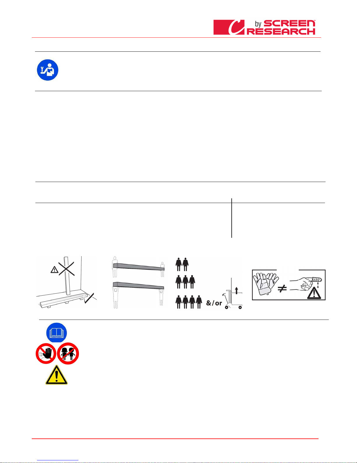
POLSKI - Instrukcja obsługi dla ekranów
Made by Adeo Screen sp.
Z o.o. (Polska) Specifications a
re subject to change without notice. E&OE
Please verify that you are working with the latest revision of this document before specifying your screen.
Doc: Manual CLCTS-CLCLT rev5 | 03.02.2015| Download at: www.screenresearch.com 2015 AdeoSreen All Rights Reserved.
Page
22
01
01 01
01 WSTEP
WSTEPWSTEP
WSTEP
Niniejszy podręcznik stanowi część skła dową produktu, a jego przeczytanie i zrozumienie mają podstawowe znaczenie dla zachowan ia bezpieczeństwa. Zostały w nim opisane zasady i
sposoby użytkowania, pozwalające klien towi na właściwe i bezpieczne korzystanie z ekranu. Podręcznik powinien zawsze znajdować się w pobliżu produktu, należy przechowywać go w
miejscu gwarantującym nie zniszczenie oraz łatwo dostępnym dla osób upoważnionych. Każdy użytkownik ekranu jest odpow iedzialny za przechowywanie podręcznika. Użytkownik jest
również odpowiedzialny za kontrolę dzia łania ekranu oraz za naprawy lub wymiany części podlegających zużyciu, mogących spow odować uszkodzenia.
Rysunki zawarte w podręczniku mają za zadanie opisać w sposób szczegółowy funkcje, charakterystykę lub procedury. Rysunki mogą róż nić się z zależności od przedstawionego modelu,
nie powoduje to jednak zmiany opisowego z naczenia rysunku.
02
02 02
02 OGÓLNA CHARAKTERYSTYKA PRODUKTU
OGÓLNA CHARAKTERYSTYKA PRODUKTUOGÓLNA CHARAKTERYSTYKA PRODUKTU
OGÓLNA CHARAKTERYSTYKA PRODUKTU
Ekran projekcyjny jest wytwarzany zgod nie z przepisami następujących dyrektyw CE:: - 2006-95-CE LDV Niskiego napięcia
- 2004-108-CE EMC Zgodności elekt romagnetycznej
- 1999-05-CE R&TTE aparatury radiowej i terminali telekomunikacyjnych
- 2005-32-CE dotyczącą Ekoprojektu dla produktów wykorzystujących energię
- 2011-65-CE ROHS Ograniczenie stosowa nia niektórych niebezpiecznych substancji
- 2002-96-CE RAEE w sprawie utylizac ji zużytego sprzętu elektrycznego
- 2001-95-CE Ogólne bezpieczeństwo produktów
Ekran opisany w niniejszym podręcznik u musi być stosowany wyłącznie jako wsparcie dla projekcji wideo. Wszelkie inne użcie jest niez godne oraz nie jest objęte treścią niniejszego podręcznika.
Ekran posiada jedną lub więcej tkanin projekcyjnych z plastycznego PVC nie za wierających kadmu lub z impregnowanego wł ókna szklanego impregnowanego plastycz
nym PVC, k ażda tkanina może być
sklasyfikowana w następujący sposób:
- M1 lub M2 zgodnie z r egulacjami francuzkimi (LNE Laboratoire national de m étrologie et d’essais – SME Centre de recherches du Bouchet -
WARRINGTONFIRE GENT La boratoire de métrologie et
d’essais – IFTH Laboratoire accreditè ) ,
- B1 lub B2 zgodnie z regulacjami niemieckimi (LNE Laboratoire national de métrologie et d’essais – SME Centre de recherches du Bouchet -
WARRINGTONFIRE GENT Laboratoire national de
métrologie et d’essais),
- UL94HB zgodnie z regulacjami am erykańskimi (THE GOVMARK Organization, Inc.).
Ponieważ nie istnieje jeszcze ha rmonizacja na poziomie europejskim pomiędzy różnymi krajowymi norm ami klasyfikacji trudnopalności, wyjaśniamy, że francuska
klasa M1 odpowiada materiałom n iepalnym a
klasyfikacja M2 materiałom nie łatwopaln .
03 ROZPAKOWANIE EKRANU I PRZEMIESZCZANIE PRODUKTU
03 ROZPAKOWANIE EKRANU I PRZEMIESZCZANIE PRODUKTU03 ROZPAKOWANIE EKRANU I PRZEMIESZCZANIE PRODUKTU
03 ROZPAKOWANIE EKRANU I PRZEMIESZCZANIE PRODUKTU
Należy upewnić się, że żaden z elementów ekranu nie został uszkodzony podczas transportu. W razie wystąpienia anomalii należy natychmiast zawiadomić o tym fakcie sprzedawcę. Sprawdzić czy w
opakowaniu znajduje się całość wyposażenia opisanego w instrukcji, odpowiednio dla danego typu ekranu.
Ekran z napędem wysuwu z wbudowanym sterowaniem radiowym
Ekran z napędem wysuwu z wbudowanym sterowaniem radiowymEkran z napędem wysuwu z wbudowanym sterowaniem radiowym
Ekran z napędem wysuwu z wbudowanym sterowaniem radiowym
Ekran z napędem wysuwu na korbkę
Ekran z napędem wysuwu na korbkęEkran z napędem wysuwu na korbkę
Ekran z napędem wysuwu na korbkę
-
2 zestawy listew do instalacji (dla ekranów do szerokości 3 m)
-3 zestawy listew do instalacji (dla ekranów powyżej szerokości 3 m)
-2 listwy boczne (dla ekranów w wersji bez kasety)
-1 przełącznik jednobiegunowy 10°, 250V obsługiwany ręcznie, ze strzałkami kierunkowymi, zawierający puszkę do montażu na ścianie
-1 nadajnik radiowy (dla ekranów z wbudowanym sterowaniem radiowym)
-1 klucz sześciokątny plastikowy
-1 instrukcja użytkowania
(opakowanie nie zawiera wkrętów i kołków rozporowych do ścian)
-
2 zestawy listew do instalacji (dla ekranów do szerokości 3 m)
-3 zestawy listew do instalacji (dla ekranów powyżej szerokości
3 m)
-1 drążek sterujący
-1 instrukcja użytkowania
(opakowanie nie zawiera wkrętów i kołków rozporowych do
ścian)
UWAGA
UWAGAUWAGA
UWAGA do otwierania opakowania nie należy używać nożyków czy innych ostrych narzędzi. Stosować zawsze rękawice ochronne podczas otwierania i instalacji czy przenoszenia produktu. Produkt należy
przenosić czy instalować minimum w dwie lub cztery osoby, w zależności od ciężaru ekranu (wartości odnośnie dopuszczalnego ciężaru na osobę to: 25kg mężczyzna - 15kg kobieta). W przypadku większych
ciężarów zaleca się stosowanie odpowiednich urządzeń do podnoszenia ładunków.
04
04 04
04 OGÓLNE NORMY BEZPIECZEŃSTWA
OGÓLNE NORMY BEZPIECZEŃSTWAOGÓLNE NORMY BEZPIECZEŃSTWA
OGÓLNE NORMY BEZPIECZEŃSTWA
Przed rozpoczęciem użytkowania produktu oraz wykonaniem jakichkolwiek czynności konserwacyjnych upewnić się, że informacje zawarte w tym podręczniku zostały przeczytane i
dobrze zrozumiane. Sprawdzać przed rozpoczęciem i podczas użytkowania czy ekran nie powoduje powstawania niebezpiecznych sytuacji. Zakaz instalacji ekranów projekcyjnych
nad ciągami komunikacyjnymi. Nie demontować, nie usuwać i nie uszkadzać żadnego elementu lub części ekranu.
Nie wykonywać nigdy czynności naprawczych przy załączonym silniku ekranu (dla zwiększenia bezpieczeństwa odłączyć od zasilania).
Zabrania się używania produktu przez dzieci. Absolutnie zabrania się dziecion zbliżania do ekranu podczas jego funkcjonowania.
Każdy ekran posiada gwarancję, której ważność zależy od rzeczywistego stosowania się do instrukcji zawartych w tym podręczniku i postępowania zgodnie z nimi.
UWAGA:
UWAGA:UWAGA:
UWAGA: Błędna instalacja może zagrażać bezpieczeństwu osób, które używają ekran. Producent nie ponosi odpowiedzialności za szkody materialne i uszczerbki na zdrowiu osób
spowodowane błędną instalacją, nieodpowiednim użytkowaniem ekranu, złą lub niewystarczającą konserwacją.
Producent nie ponosi odpowiedzialności za problemy spowodowane błędami przy instalacji.
Instalacja ekranu, połączenia elektryczne oraz kontrola w wypadku złego funkcjonowania automatycznego zwijania powinny być wykonywane przez autoryzowanego sprzedawcę
lub przez przeszkolony personel, znający niebezpieczeństwa, jakie może spowodować prąd elektryczny. Nie wolno wymieniać przewodu zasilania. Jeśli przewód jest uszkodzony
ekran musi być wymieniony. Naruszenie wyłączników krańcowych lub przerwanie plomby umieszczonej powyżej otworów powoduje utratę gwarancji. W wypadku konieczności
wyjaśnień prosimy o skontaktowanie się z naszym biurem technicznym.
PO ZAKOŃCZENIU MONTAŻU EKRANU NA LISTWACH NIEZBĘDNE JEST SKONTROLOWANIE DOKŁADNOŚCI USTAWIENIA W POZIOMIE PRZED ROZPOCZĘCIEM UŻYTKOWANIA.
Page 23
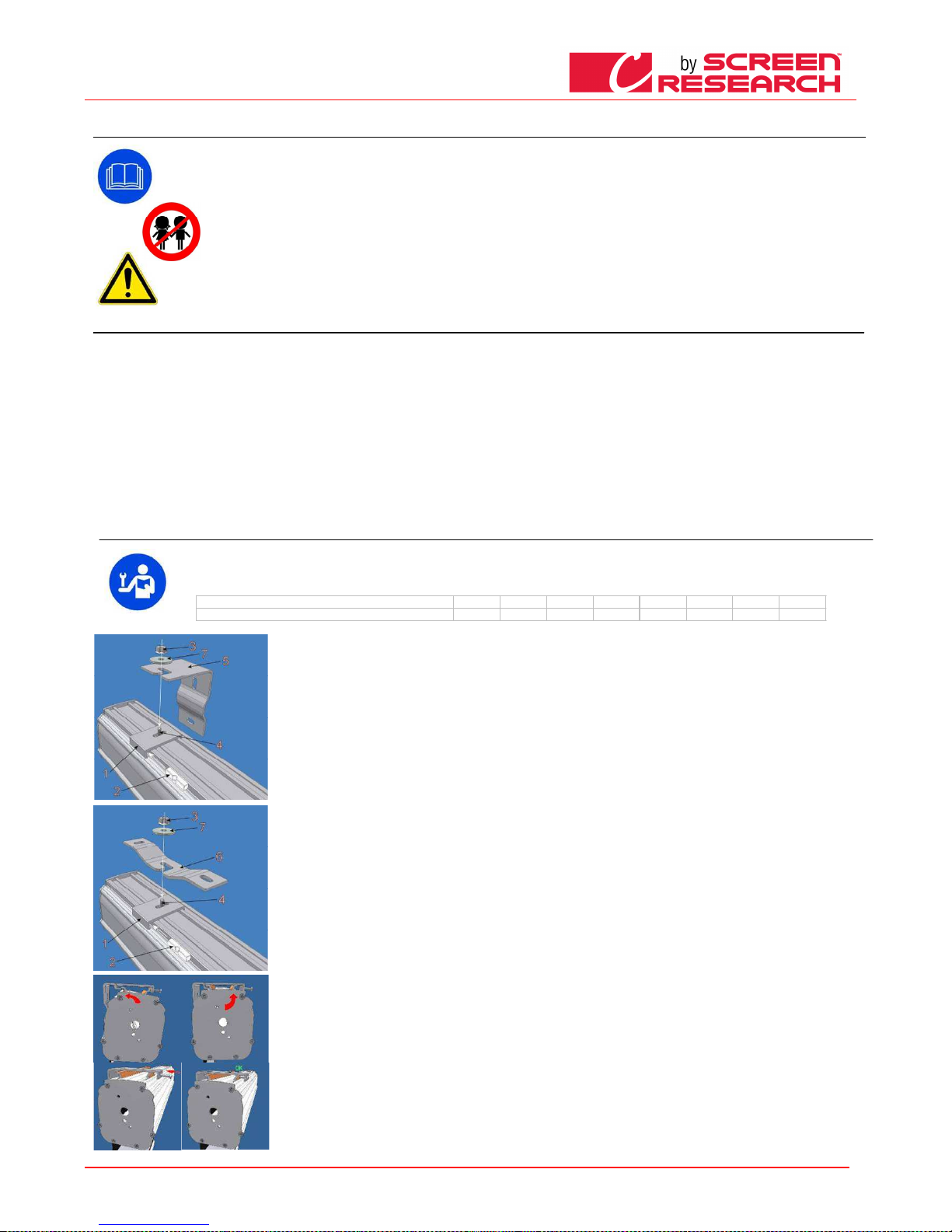
POLSKI - Instrukcja obsługi dla ekranów
Made by Adeo Screen sp.
Z o.o. (Polska) Specifications a
re subject to change without notice. E&OE
Please verify that you are working with the latest revision of this document before specifying your screen.
Doc: Manual CLCTS-CLCLT rev5 | 03.02.2015| Download at: www.screenresearch.com 2015 AdeoSreen All Rights Reserved.
Page
23
05
05 05
05 OSTRZEŻENIA I UWAGI DO UŻYTKOWANIA
OSTRZEŻENIA I UWAGI DO UŻYTKOWANIA OSTRZEŻENIA I UWAGI DO UŻYTKOWANIA
OSTRZEŻENIA I UWAGI DO UŻYTKOWANIA
Ekrany dedykowane są do zastosowań w pomieszczeniach o normalnych warunkach temperatury (20 - 25 °C) i wilgotności. Szczególną ostrożność należy zachować przy
zastosowaniu na zewnątrz, przede wszystkim w odniesieniu do temperatur i zapylenia. Wystawienie na temperatury powyżej 50 °C może spowodować stałe odkształcenie
powierzchni ekranu lub odklejenie się materiału projekcyjnego od rolki zwijania.
Dla uniknięcia żółknięcia ekranu, nie należy wystawiać go przez dłuższy czas na działanie promieni słonecznych (należy sprawdzać także czy z powodu działania takich promieni,
ekran nie osiąga poziomów temperatur wskazanych powyżej).
Ponieważ materiał, z którego wykonana jest powierzchnia projekcyjna (PVC) może w łatwy sposób zostać naładowany elektrostatycznie, nadmierne zapylenie otoczenia
spowodować może obniżenie właściwości optycznych ekranu, co związane jest z odkładaniem się pyłów przyciąganych elektrostatycznie (patrz także: czyszczenie ekranu
projekcyjnego).
UWAGA:
UWAGA:UWAGA:
UWAGA: Nie wymuszać ręcznego wysuwania ekranu ponieważ mogłoby to spowodować uszkodzenie silnika lub oderwanie kasety od elementów montażowych.
Nie pozwalać dzieciom bawić się stałymi urządzeniami sterującymi. Pilot przechowywać w miejscu niedostępnym dla dzieci.
Obserwować ekran gdy znajduje się w ruchu dopilnowując, aby nikt nie zbliżał się do ekranu dopóki nie zostanie on całkowicie zamknięty.
Zabrania się blokować, zatrzymywać czy wymuszać ruch ekranu, przytrzymywać się lub zawieszać, dołączać lub instalować jakiekolwiek przedmioty na ekranie lub na tylnej jego
części, modyfikować konstrukcję ekranu; zachowania takie mogą spowodować uszkodzenia sytemu zwijania, co z kolei mogłoby sprowokować niebezpieczeństwo dla osób czy
przedmiotów.
06
06 06
06 CZYSZCZENIE I KONSERWACJA
CZYSZCZENIE I KONSERWACJACZYSZCZENIE I KONSERWACJA
CZYSZCZENIE I KONSERWACJA
Ekran oraz tkaniny proje kcyjne stosowane na ekranach są wykonane z materia łów delikatnych, należy więc zachować szczególną ostro żność przy ich czyszczeniu, wykonując te czynności w nast ępujący sposób:
Nigdy nie używać rozpus zczalników, produktów chemicznych, ściernych c zy też zaostrzonych przyrządów do czyszczenia powierzchni.
Unikać wszelkiego kontaktu z innymi materiałami (lakiery, tusz itp.), pon ieważ usunięcie ich z tkaniny może okazać się niemożliwe.
TKANINY PROJEKCYJ NE CL
TKANINY PROJEKCYJ NE CLTKANINY P ROJEKCYJNE CL
TKANINY PROJEKCYJ NE CLEARPIX
EARPIXEARPIX
EARPIX: Stosować miękką, czystą, wilgotną ściereczkę, wykonując ruchy poczynając o d środka powierzchni projekcyjnej w kierunku na zewnątrz. Możliwe jest używanie szczotki
zamontowanej na odkur zaczu, ale wyłącznie wtedy, gdy jej włosie jest miękkie i dokładnie oczyszczone.
TKANINY PROJEKCYJ NE
TKANINY PROJEKCYJ NE TKANINY PROJEKCYJ NE
TKANINY PROJEKCYJ NE SOLIDPIX, MULTIPIX,
SOLIDPIX, MULTIPIX,SOL IDPIX, MULTIPIX,
SOLIDPIX, MULTIPIX,: Do c zyszczenia materiału projekcyjnego stosować m iękką, czystą, wilgotną ściereczkę, ewentualnie w połąc zeniu z detergentami na bazie obojętnej lub alkoholu.
Ponieważ po oczyszczen iu ekran z powodu tarcia ściereczki może naładować s ię prądem statycznym, doradza się przetrzeć materiał cz ystą ściereczką nasączoną płynem antystatycznym, dla u niknięcia
ponownego przyciągania pyłów. Okresowo kontrolować system mocując y i połączenia elektryczne
TKANINY PRO
TKANINY PROTKANINY PRO
TKANINY PRO JEKCYJNE SILVERPIX
JEKCYJNE SILVERPIX JEKCYJNE SILVERPIX
JEKCYJNE SILVERPIX ob owiązkowe jest przeczytanie instrukcji dołączonych ekra n tkaniny
PROFILE
PROFILE PROFILE
PROFILE Do czyszczenia profilu stosować miękką, czystą ściereczkę lub szczotki z miękkim i antystatycznym włosiem
PROFILE RAMY z WELURU
PROFILE RAMY z WELURUPRO FILE RAMY z WELURU
PROFILE RAMY z WELURU: Do czyszczenia pr ofilu stosować m iękką, czystą ściereczkę lub szczotk i z miękkim i antystatycznym włosiem. Możliwe je st używanie szczotki zamontowanej na odk
urzaczu, ale
wyłącznie wtedy, gdy jej włosie jest miękkie i dokładnie oczyszczone.
KONSTRUKCJA i LISTWY MONTAŻOW E:
KONSTRUKCJA i LISTWY MONTAŻOW E:KONSTRU KCJA i LISTWY MON TAŻOWE:
KONSTRUKCJA i LISTWY MONTAŻOW E: Niezbędne jest ok resowe kontrolowania stanu produktu oraz wytr zymałości listew montażowy ch. W przypadku p ojawienia się odkształce ń, rozdarć l
ub konstrukcy jnych
uszkodzeń listew, wkrętów czy komponentów produktu należy nieodzownie zabezpieczyć okoliczną strefę dla uniknięc
ia wszelkich szkód czy zagrożeń dla osób i przedm iotów. Następnie trze ba podjąć
działania mające na cel u natychmiastową wymianę uszkodzonej części i naprawę produktu.
07
07 07
07 INSTRUKCJA INSTALACJI
INSTRUKCJA INSTALACJIINSTRUKCJA INSTALACJI
INSTRUKCJA INSTALACJI
UWAGA:
UWAGA:UWAGA:
UWAGA: Jest to absolutnie zabronione, aby zainstalować ekran na ruchomymi ścianami lub kabli niestabilnych, wsporniki należy stoso wać na powierzchniach, które zapewniają w tym
czasie dystans. Do instalacji ekranu na leży zastosować wkręty i kołki rozporowe odpowiednie dla ciężaru i rodzaju ściany lub sufitu , na jakich zamierzamy zamontować elementy
mocujące. Przed rozpoczęciem montaż u wybrać rodzaj kołków lub mocowania zgodnie z następującym schematem:
Ekran o szerokości do cm
Ekran o szerokości do cmEkran o szerokości do cm
Ekran o szerokości do cm
16
1616
16
0000
200
200200
200
250
250250
250
300
300300
300
360
360360
360
410
410410
410
520
520520
520
620
620620
620
Całkowity ciężar jaki należy prz ewidzieć
Całkowity ciężar jaki należy prz ewidziećCałkowity ciężar jaki należ y przewidzieć
Całkowity ciężar jaki należy prz ewidzieć
Kg 20
Kg 20Kg 20
Kg 20
Kg 25
Kg 25Kg 25
Kg 25
Kg 30
Kg 30Kg 30
Kg 30
Kg 35
Kg 35Kg 35
Kg 35
Kg 45
Kg 45Kg 45
Kg 45
Kg 50
Kg 50Kg 50
Kg 50
Kg 100
Kg 100Kg 100
Kg 100
Kg 150
Kg 150Kg 150
Kg 150
INSTALACJA NA ŚCIANIE:
INSTALACJA NA ŚCIANIE:INSTALACJA NA ŚCIANIE:
INSTALACJA NA ŚCIANIE:
wprowadzić wkręt 4 z gw intem skierowanym w górę, do płytki 1 i lekko przykręcić nakrętkę 3 pozostawiając 4-5 mm luzu; założyć płytkę 1 na kasetę i
wprowadzić plastikowy kołek 2 do wysunięcia w listwie. N ależy podkreślić, że dla montażu nie jest istotne którą stroną montujemy płytkę, ponieważ profile,
które zaczepiane są do ka sety są całkowicie symetryczne. Umocować do ściany listwę 5 za pomocą kołków rozporowych, odpow iednich do rodzaju ściany
(minimum Ø 8 mm), a następnie zamontow ać płytkę 1 za pomocą listwy 5 używając w tym celu podkładki 7 i nakrętki 3.
INSTALACJA DO SUFITU:
INSTALACJA DO SUFITU: IN STALACJA DO SUFITU:
INSTALACJA DO SUFITU:
umocować do sufitu listwy 6, dostarczo ne standardowo wraz z ekranem, za pomocą kołków rozporowych odpowiednich do rodza ju ściany (minimum Ø 8 mm),
w odległości około 10 - 15 cm od końców kasety. W wypadku ekranów o szerokości większej niż 350 cm trzecia lista powinna być umieszczo na w środku
kasety. Wprowadzić wkręt 4 z gwintem skierowanym w górę, do płytki 1 i lekko przykręcić nakrętkę 3 pozostawiając 4-5 mm luzu; założyć pły tkę 1 na kasetę i
wprowadzić plastikowy kołek 2 do wys unięcia w listwie. Zamontować płytkę 1 za pomocą listwy 6 używając w tym celu podkładki 7 i nakrętki 3.
Bezpośrednia instalacja do sufitu za pomo cą płytek mocujących:
Możliwa jest instalacja bezpośrednio d o sufitu płytek mocujących 1 jeśli chcemy, aby kaseta dokładnie przylegała do sufitu (uwaga: d la łatwego i szybkiego
wykonania instalacji sufit powinien być możliwie najbardziej równy, a płytki zamocowane idealnie w linii). Płytki przymocować z a pomocą kołków rozporowych,
odpowiednich do rodzaju podłoża (min imum Ø 8 mm), około 10 - 15 cm od końców kasety. W wypadku takiego montażu strona płyt ki, w którą montowany jest
kołek mocujący, zwykle skierowana jes t do przedniej części kasety, aby ułatwić wprowadzenie kołka. Sprawdzić dokładnie ułożenie w linii i wypoziomowanie
płytek. W celu wyregulowania płytek st osować można podkładki metalowe załączone w opakowaniu. Pamiętać należy, że od dokładnośc i wykonania tej
czynności zależy szybkość i łatwość nas tępnej, czyli umocowania kasety do płytek. W wypadku ekranów o szerokości większej niż 350 cm trzecia lista powinna
być umieszczona w środku kasety. Umo cować kasetę w płytkach ruchem półobrotowym (mocowanie impulsowe) oraz wprowadzić ko łki plastikowe dla
zabezpieczenia mocowania kasety w pł ytkachINSTALLAZIONE
INSTACJA ZA POMOCĄ UCHWYTU S ZYBKIEGO MONTAŻU:
INSTACJA ZA POMOCĄ UCHWYTU S ZYBKIEGO MONTAŻU:INSTACJA ZA POMOCĄ UCHWYTU SZYBKIEGO MONTAŻU:
INSTACJA ZA POMOCĄ UCHWYTU S ZYBKIEGO MONTAŻU:
1) wykonać mocowanie listew za pomocą odpowiednich kołków rozporowych (minimum Ø 8 mm) (możliwe jest mocowanie do sufitu lub na ścianie)
kontrolując ich wypoziomowanie;
2) umocować ekran do listew ;
Page 24
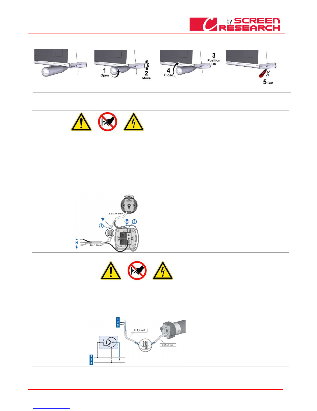
POLSKI - Instrukcja obsługi dla ekranów
Made by Adeo Screen sp.
Z o.o. (Polska) Specifications a
re subject to change without notice. E&OE
Please verify that you are working with the latest revision of this document before specifying your screen.
Doc: Manual CLCTS-CLCLT rev5 | 03.02.2015| Download at: www.screenresearch.com 2015 AdeoSreen All Rights Reserved.
Page
24
08
08 08
08 REGULACJA NAPIĘCIA OBCIĄŻNIKA W SYSTEMIE TENSIO
REGULACJA NAPIĘCIA OBCIĄŻNIKA W SYSTEMIE TENSIOREGULACJA NAPIĘCIA OBCIĄŻNIKA W SYSTEMIE TENSIO
REGULACJA NAPIĘCIA OBCIĄŻNIKA W SYSTEMIE TENSIO
09
09 09
09 CHARAKTERYSTYKA
CHARAKTERYSTYKACHARAKTERYSTYKA
CHARAKTERYSTYKA SILNIKA
SILNIKA SILNIKA
SILNIKA –––– DANE TECHNICZNE
DANE TECHNICZNE DANE TECHNICZNE
DANE TECHNICZNE –––– POŁĄCZENIE ELEKTRYCZNE
POŁĄCZENIE ELEKTRYCZNEPOŁĄCZENIE ELEKTRYCZNE
POŁĄCZENIE ELEKTRYCZNE
Typ zainstalowanego w produkcie silnika opisany jest na etykiecie posiadającej oznakowanie CE, a znajdującej się na każdym produkcie. W trakcie otwierania opakowania należy skontrolować etykietę i
ustalić rodzaj silnika, aby wykonać poprawną instalację i prawidłowe okablowanie. W przypadku, kiedy moc silnika nie odpowiada mocy linii elektrycznej w miejscu instalacji urządzenia, prosimy o
skontaktowanie się z elektrykiem i wyposażenie we właściwy transformator prądu i częstotliwości.
POŁĄCZENIE ELEKTRYCZNE
POŁĄCZENIE ELEKTRYCZNEPOŁĄCZENIE ELEKTRYCZNE
POŁĄCZENIE ELEKTRYCZNE:
Okablowanie elektryczne musi respektować obowiązujące normy CEI. Norma CEI EN 60335-1 przewiduje w sieci
zasilania urządzenie rozłączające wielobiegunowe, o szerokości otwarcia styków co najmniej 3 mm. Do sterowania
ekranu używać jedynie przełącznik dostarczony z ekranem, lub inny odpowiednik, zgodnie ze wskazówkami schematu
połączeń na Rys. 4 (jeśli silnik zamontowany j est po lewej stronie należy odwrócić kolory przewodów w następujący
sposób: w dół = brązowy, w górę = czarny). Przełącznik powinien zostać zamontowany w widocznym miejscu, na
wysokości pomiędzy 1.5 a 1.8 m od podłogi. Podłącznie przewodów do przełącznika znajdującego się na
wyposażeniu wykonać należy usuwając przednie klawisze, uzyskując w ten sposób dostęp do przycisków zał./wył.
UWAGA:
UWAGA:UWAGA:
UWAGA:
Właściwe wykonanie połączeń elektrycznych, zgodnie ze sztuką i w zachowaniu obowiązujących norm prawnych, jest
istotne dla zabezpieczenia przed wypadkami oraz właściwego i niezmiennego działania ekranu.
Przed wykonaniem jakichkolwiek czynności w instalacji elektrycznej, upewnić się, że napięcie zostało odłączone.
Silnik ekranów wyposażonych w kasetę umieszczony jest po prawej stronie ekranu patrząc od jego frontu (na
zamówienie możliwe jest umieszczenie silnika po stronie lewej). Nie podłączać nigdy dwóch lub więcej silników do
jednego przełącznika bez sterowania połączonego lub dwóch przełączników przy tym samym silniku.
Somfy
Somfy Somfy
Somfy 230V 50Hz
230V 50Hz230V 50Hz
230V 50Hz
Dane techniczne silnika
Dane techniczne silnikaDane techniczne silnika
Dane techniczne silnika
Częstotliwość: ~Hz50
Moc: 90W
Moment obrotowy: 6Nm
Prędkość: 12Rpm
Maksymalna liczba cykli: 2
Długość przewodu: 3m
Wytrzymałość mechaniczna:
zgodnie z normą EN14202
Temperatura pracy:
od –20 do +55 °C
Połączenia dla każdego silnika:
Połączenia dla każdego silnika:Połączenia dla każdego silnika:
Połączenia dla każdego silnika:
Niebiesky (Wspòlny)
Brazowy (Gorà)
Czamy (Dol)
Żółto-zielony (Uziemienie
230V)
Somfy
SomfySomfy
Somfy120V 60Hz
120V 60Hz120V 60Hz
120V 60Hz
Dane techniczne silnika
Dane techniczne silnikaDane techniczne silnika
Dane techniczne silnika
Częstotliwość: ~Hz60
Moc: 80W
Moment obrotowy: 88.in.lb
Prędkość: 14r/min
Maksymalna liczba cykli: 2
Długość przewodu: 3m
Wytrzymałość mechaniczna:
zgodnie z normą EN14202
Temperatura pracy:
od –20 do +55 °C
Połączenia dla każdego silnika:
Połączenia dla każdego silnika:Połączenia dla każdego silnika:
Połączenia dla każdego silnika:
Bialy(Wspòlny)
Czamy (Dol)
Czerwony (Gorà)
Żółto-zielony (Uziemienie
120V)
PODŁĄCZENIE ELEKTRYCZNE:
PODŁĄCZENIE ELEKTRYCZNE:PODŁĄCZENIE ELEKTRYCZNE:
PODŁĄCZENIE ELEKTRYCZNE:
Okablowanie elektryczne musi respektować obowiązujące normy WE. Norma WE EN 60335-1 przewiduje w sieci zasilania istnienie wielobiegunowego urządzenia
rozłączającego, o szerokości otwarcia styków co najmniej 3 mm dla każdego silnika (z wyłączeniem wtyczki itp.). W razie potrzeby to urządzenie zapewnia bezpieczne
i szybkie odcięcie źródła zasilania. Kable łączyć jak pokazano na rysunku po prawej stronie.
UWAGA:
UWAGA:UWAGA:
UWAGA:
Właściwe wykonanie połączeń elektrycznych, zgodnie ze sztuką i w zachowaniu obowiązujących norm prawnych, jest istotne dla zabezpieczenia przed wypadkami
oraz właściwego i niezmiennego działania ekranu. Przed wykonaniem jakichkolwiek czynności w instalacji elektrycznej, upewnić się, że napięcie zostało odłączone.
Silniki umieszczone są po prawej stronie ekranu patrząc od jego frontu.
Uruchamianie wykonywane jest za pomocą pilota na fale radiowe dostarczanego w standardzie.
Somfy RTS 230V 50Hz
Somfy RTS 230V 50HzSomfy RTS 230V 50Hz
Somfy RTS 230V 50Hz
Dane techniczne silnika
Dane techniczne silnikaDane techniczne silnika
Dane techniczne silnika
Częstotliwość: ~Hz50
Moc: 120W
Moment obrotowy: 10Nm
Prędkość: 17Rpm
Maksymalna liczba cykli: 2
Długość przewodu: 3m
Temperatura pracy:
od –20 do +55 °C
Częstotliwość: 433.92 MHz
Zasięg nadajnika: 150mt
Połączenia dla każdego silnika:
Połączenia dla każdego silnika:Połączenia dla każdego silnika:
Połączenia dla każdego silnika:
Brązowy (Linia 230V)
Niebieski (Faza 230V)
Żółto-zielony (Uziemienie
230V)
Page 25
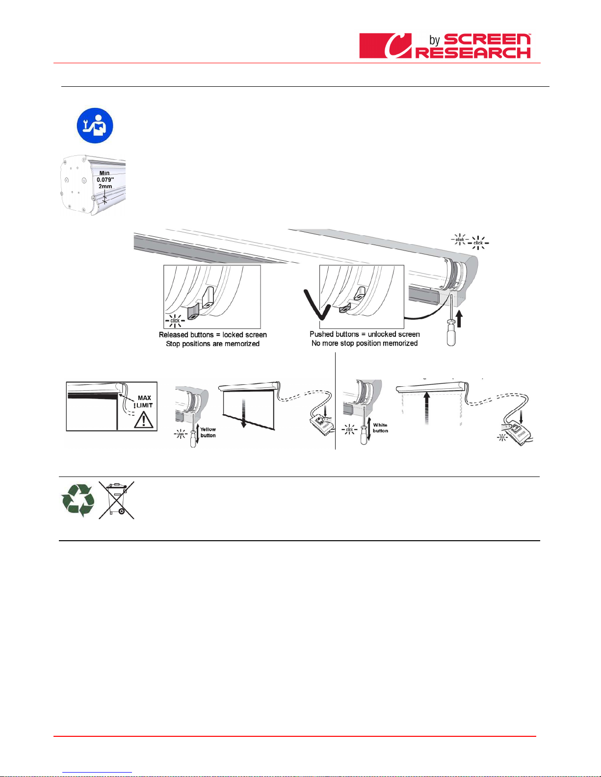
POLSKI - Instrukcja obsługi dla ekranów
Made by Adeo Screen sp.
Z o.o. (Polska) Specifications a
re subject to change without notice. E&OE
Please verify that you are working with the latest revision of this document before specifying your screen.
Doc: Manual CLCTS-CLCLT rev5 | 03.02.2015| Download at: www.screenresearch.com 2015 AdeoSreen All Rights Reserved.
Page
25
10
10 10
10 REGULACJA OGRANICZNIKÓW KRAŃCOWYCH EKRANÓW
REGULACJA OGRANICZNIKÓW KRAŃCOWYCH EKRANÓWREGULACJA OGRANICZNIKÓW KRAŃCOWYCH EKRANÓW
REGULACJA OGRANICZNIKÓW KRAŃCOWYCH EKRANÓW
UWAGA PRZECZYTAĆ PRZED WYKONANIEM REGULACJI
UWAGA PRZECZYTAĆ PRZED WYKONANIEM REGULACJIUWAGA PRZECZYTAĆ PR ZED WYKONANIEM REGULACJI
UWAGA PRZECZYTAĆ PRZED WYKONANIEM REGULACJI
Regulacje wskazane p owinny być wykonywane jedynie przez upoważnion y i specjalistyczny personel. Postępowanie niezgodne z opisanymi procedurami spowodować może
uszkodzenie produktu , nie uznawane w ramach gwarancji.
OSTRZEŻENIE
“GÓRNY OGRANICZNIK KRAŃCOWY POWINIEN BYĆ ZAWSZE USTAWIONY 2 mm OD KASETY” patrz rysunek po lewej stronie.
Ogranicznik krańcowy wyregulowany jest w taki sposób, aby materiał projekcyj ny pozostawał zawinięty na rolce co najmniej na 1,5 o brotu, dla uniknięcia jego oderwania.
Szczególnej uwagi wym aga regulacja ogranicznika wykonywana w celu r ozwijania materiału projekcyjnego poza wymiar ustawiony fabrycznie. Niewłaściwa regulacja
ograniczników może s powodować:
-Oderwanie materiału projekcyjnego od rolki
-Zwijanie materiału pr ojekcyjnego w odwrotnym kierunku uszkadzające gładko ść powierzchni projekcyjnej i mechanizm zwijania .
-Zniszczenie zgrzewu p rzy czarnej ramce, w dole (ekrany z ramką).
-Przeciążenie silnika z możliwym uszkodzeniem oraz uruchomienie oporu termicznego znajdującego się w silniku.
-Nadmierne zawinięci e systemu tarowania ograniczników krańcowych i w k onsekwencji zniszczenie części mechanicznej.
GWARANCJA
Przypomina się opera torom, że w przypadku naruszenia plomb zabezpie czających i uszkodzeń spowodowanych błędną regulac ją, wszelkie naprawy wykonywane będą poza
gwarancją.
--W celu odblokowania ustawień wyłączników krańcowych wcisnąć przyciski Biały i Żółty, jak pokazano na rysunku.
- W celu ustawienia dolnego wyłącznika krańcowego należy wysunąć powierzchnię projekcyjną do żądanej
wysokości, po czym zwolnić przycisk Żółty
- W celu ustawienia górnego wyłącznika krańcowego należy zwinąć
powierzchnię
projekcyjną do żądanej pozycji, po czym zwolnić przycisk Biały
USUWANIE ZUŻYTEGO PRODUKTU
USUWANIE ZUŻYTEGO PRODUKTUUSUWANIE ZUŻYTEGO PRODUKTU
USUWANIE ZUŻYTEGO PRODUKTU
Podobnie jak w przypa dku czynności instalacyjnych, również czynności wykonywane n a zakończenie pracy tego produktu przy jego usuw aniu powinny być zrealizowane przez
wyspecjalizowany personel. Produkt skonstruowany został z różnych materiałów: niektóre z nich mogą zostać poddane recyklingowi, inne muszą być usunięte. Nale ży
zasięgnąć informacji o sposobach recyklingu oraz u suwania odpadów, przewidzianych przez prawo obowiązujące w danym kraju i dla danej kategorii produktu. Zabronione
jest usuwanie produktu do domowych odpadów, co pokazuje symbo l zamieszczony obok. Należy więc segregować odpady przy usuwaniu produktu, zgodnie z metodami
przewidzianymi przez prawo obowiązują ce w danym kraju albo przekazać produkt sprze dawcy w momencie zakupu nowego.
Uwaga: miejscowe regulacje prawne mogą przewidywać poważne sankcje w wypadku usuwania produktu w sposób zakazany prawem.
GWARANCJA
GWARANCJAGWARANCJA
GWARANCJA
1. OGRANICZONA GWARANCJA
1. OGRANICZONA GWARANCJA1. OGRANICZONA GWARANCJA
1. OGRANICZONA GWARANCJA Screen Research gwarantuje, że niniejszy produkt jest wolny od materiałowych i wykonawczych wad produkcyjnych zgodnie z warunkami określonymi w niniejszej gwarancji.
Materiał powierzchni oraz rama są objęte pięcioletnią (5) gwarancją począwszy od daty otrzymania faktury przez oryginalnego nabywcę. Silniki, kontrolery silników, urządzenia zdalnego sterowania oraz
powiązane części montażowe są objęte trzyletnią (3) gwarancją począwszy od daty otrzymania faktury przez oryginalnego nabywcę.
2. WARUNKI I OGRANICZENIA
2. WARUNKI I OGRANICZENIA2. WARUNKI I OGRANICZENIA
2. WARUNKI I OGRANICZENIA Niniejsza Gwarancja podlega ograniczeniom wyszczególnionym poniżej. Niniejsza Gwarancja traci ważność w przypadku, gdy produkt był wykorzystywany lub obsługiwany w
sposób niezgodny ze wskazówkami zawartymi w instrukcji obsługi, używany niewłaściwie, uszkodzony w wyniku wypadku, zaniedbania lub podczas przewozu, albo gdy wada jest wynikiem naprawy lub
modyfikacji produktu przez podmiot inny niż Screen Research lub autoryzowany przez Screen Research punkt dystrybucji lub montażu. Instalacji produktu powinien dokonać autoryzowany przez Screen
Research sprzedawca lub punkt montażowy, konserwacja produktu powinna być przeprowadzana w sposób zgodny z pisemnymi wskazówkami.
3. ZWROTY
3. ZWROTY3. ZWROTY
3. ZWROTY Nie przyjmuje się zwrotów produktu bez uprzedniej pisemnej autoryzacji przez Screen Research. Produkt powinien być umieszczony w oryginalnym opakowaniu, wraz z oryginalną zawartością, lub w
opakowaniu równie dobrze zabezpieczonym, tak aby uniknąć uszkodzeń w trakcie transportu. Produkt w opakowaniu należy zwrócić do Screen Research bądź do autoryzowanego centrum serwisowego Screen
Research. Użytkownik jest odpowiedzialny za dokonanie zwrotu i ponosi jego koszt. Screen Research dokona opłaty za przesyłkę zwrotną wybranego rodzaju. DO ZWRÓCONEGO PRODUKTU POWINIEN BYĆ
DOŁĄCZONY PISEMNY OPIS WADY ORAZ KSEROKOPIA ORYGINALNEGO DOWODU ZAKUPU. Dowód zakupu powinien w sposób wyraźny wskazywać model, datę zakupu, nazwisko i adres nabywcy oraz
autoryzowanego sprzedawcy, a także cenę nabycia. Screen Research zastrzega sobie prawo modyfikacji konstrukcji dowolnego produktu bez uprzedzenia i bez zobowiązań wobec nabywców uprzednio
wyprodukowanych produktów, a także do zmiany cen lub specyfikacji dowolnego produktu.
4. ŚRODKI NAPRAWCZE
4. ŚRODKI NAPRAWCZE4. ŚRODKI NAPRAWCZE
4. ŚRODKI NAPRAWCZE W okresie obowiązywania niniejszej Ograniczonej Gwarancji, w przypadku gdy produkt nie spełnia warunków określonych w niniejszej Gwarancji nabywca, zgodnie z niniejszą
Ograniczoną Gwarancją, ma prawo wyłącznie do zwrotu produktu do Screen Research lub autoryzowanego przez Screen Research centrum serwisowego, gdzie wada zostanie usunięta bez obciążania
użytkownika kosztami robocizny i części zamiennych.
5. OGRANICZENIE GWARANCJI DO ORYGINALNEGO NABYWCY
5. OGRANICZENIE GWARANCJI DO ORYGINALNEGO NABYWCY5. OGRANICZENIE GWARANCJI DO ORYGINALNEGO NABYWCY
5. OGRANICZENIE GWARANCJI DO ORYGINALNEGO NABYWCY Niniejsza Gwarancja obejmuje wyłącznie oryginalnego nabywcę objętego nią produktu. Nie istnieje możliwość przeniesienia jej na kolejnych
nabywców produktu.
6. POSTANOWIENIA RÓŻNE
6. POSTANOWIENIA RÓŻNE6. POSTANOWIENIA RÓŻNE
6. POSTANOWIENIA RÓŻNE Wszelkie domniemane gwarancje dotyczące produktów Screen Research ograniczone są czasem trwania niniejszej Gwarancji. Gwarancja nie obejmuje odpowiedzialności za szkody
przypadkowe lub wynikowe nabywcy. Niektóre państwa nie dopuszczają ograniczeń terminu obowiązywania domniemanych gwarancji ani wyłączania lub ograniczania odpowiedzialności za szkody
przypadkowe lub wynikowe, tym samym powyższe ograniczenia mogą nie mieć zastosowania w Państwa przypadku. Na mocy niniejszej Gwarancji przysługują Państwu określone prawa. Dodatkowo mogą
Państwu przysługiwać inne prawa w zależności od jurysdykcji.
7. GWARANT
7. GWARANT7. GWARANT
7. GWARANT Zapytania dotyczące niniejszej Ograniczonej Gwarancji można kierować na następujący adres odpowiedni dla kraju zakupu:
8. WSPARCIE GWARANCYJNE AUTORYZOWANEGO DYSTRYBUTORA
8. WSPARCIE GWARANCYJNE AUTORYZOWANEGO DYSTRYBUTORA8. WSPARCIE GWARANCYJNE AUTORYZOWANEGO DYSTRYBUTORA
8. WSPARCIE GWARANCYJNE AUTORYZOWANEGO DYSTRYBUTORA Screen Research dysponuje siecią autoryzowanych dystrybutorów w wielu krajach na całym świecie. W przypadku każdego kraju
autoryzowany Dystrybutor dokonujący importu odpowiedzialny jest za wsparcie gwarancyjne produktów sprzedawanych w danym kraju przez takiego dystrybutora lub sprzedawcę detalicznego. Serwis
gwarancyjny świadczony jest przez sprzedawcę detalicznego lub dystrybutora dokonującego importu, od którego został nabyty produkt.
Page 26
Manual
Made by Adeo Screen sp.
Z o.o. (Polska) Specifications a
re subject to change without notice. E&OE
Please verify that you are working with the latest revision of this document before specifying your screen.
Doc: Manual CLCTS-CLCLT rev5 | 03.02.2015| Download at: www.screenresearch.com 2015 AdeoSreen All Rights Reserved.
Page
26
ADEO SCREEN Sp. Z o.o.
ADEO SCREEN Sp. Z o.o.ADEO SCREEN Sp. Z o.o.
ADEO SCREEN Sp. Z o.o.
Ul. Boleslawa Krzywoustego 31
59-500 Zlotoryja, POLAND
Phone +48 76 850 53 01
Fax + 48 76 850 53 70
Email
EmailEmail
Emailssss
For commercial inquiries: [email protected]
For technical inquiries: [email protected]
© Copyright 2015 Adeo Screen. All rights reserved.
Adeo Screen products are covered by one or more of the following patents:
No. 08.02361 (France); No. 09.03989 (France); No. 167.61.72 (Europe); No. 167.75.55 (Europe); No. EP 2277083 (Europe);
No. US 7 777 947-B2 (USA); No. US 7 466 483-B2 (USA); No. US 2011 043908 (USA); USPTO : 200 701 71 522 (USA);
No. 200480025260.9 (China); No. 1126/CHENP/2007 (India); No. 2006-524398 (Japan) pending;
ClearPix 2, ClearPix 4, SilverPix 3D, SilverPix 3D Sonic, MultiPix 4K, SolidPix, SolidPix Sonic, X-Mask, E-Mask, LeWing, TheaterCurve, Pi-Grip, E-Grip, StopLight, DécorMask,
TailorMade and the Screen Research logo are all trademarks of Adeo Screen.
THX is a trademark of THX Ltd.
ISF is a trademark of Imaging Science Foundation Inc..
Sivoia QED and Sivoia QS are the registered trademarks of Lutron Electronics Co., Inc..
All other trademarks are the property of their respective owners.
 Loading...