

Page 1
Wave Digital Marine TV Antenna
MOUNTING OPTIONS
FITTING ‘F’ CONNECTOR
Vari abl e S ignal Bo oster x 1
‘F’ to Coax ial F lyl ead x 1
12/ 24V fu sed p ower cable x 1
Scr ew x 2
A:
B:
C:
D:
A
B
PACK CONTENTS
D
E
F
No pictu re on T V
■ Che ck amp lif ier LE D is on
■ Che ck coa xia l c able connecti ons
■ Adju st ga in of am plifie r
■ TV or s et top b ox not tune d in
■ Poor r ecepti on ar ea
Pic tur e bre aks u p o r fre ezes
■ Adju st ga in of am plifie r
■ Poor r ecepti on
Pow er LED d oes n ot illum ina te when pow er is sw itched on
■ No power, chec k oth er devic es on sa me el ectric al ci rcuit
■ Fuse has b
low n
H
■ Helpline: +44 (0) 1553 811000
FAULT FINDING
2 YEAR GUARANTEE
A:
B:
C:
D:
E:
F:
G:
H
:
Wall fixing hole
On/off power switch
LED power indicator
Gain control knob
12/ 24V po wer i nput
Antenn a i nput
TV/ Radio ou tput
TV/ Radio ou tput
SAFETY WARNINGS
C
SPECIFICATIONS
1
/4”
Des ign ed for
con tin uou s use
Des ign ed for
ind oor use only
Thi s s ignal bo oster is g uara nteed again st de fec tive parts or
wor kma nsh ip for 2 year s fro m tim e of purchase. T his e xclude s any
mal fun cti on cause d b e imp roper us e, ac cident al or mali cious
dam age
or remo val o f t he ou ter c asi ng. Th is do es no t aff ect yo ur
sta tutory ri ght s.
TO
AER IAL
EXT RA TV/RA DIO
OUT PUT IF REQU IRED
POWE R CON NEC TIO N
RED +12/ 24V BL ACK 0 V
TO TV ‘ F’
COAX IAL
FLYLEAD
12/ 24V FU SED C ONN ECT ION
ON
1. Slid e pow er sw itch to right. LED indic ato r s hould no w be on.
2. Tur n g ain c ontrol knob cloc kwi se to in crease sign al st rength.
10m m
12m m
1
2
CONNECTION DIAGRAM
FITTING ‘F’ CONNECTOR
MOUNTING OPTIONS
OPERATION
Vari abl e S ignal Bo oster x 1
‘F’ to Coax ial F lyl ead x 1
12/ 24V fu sed p ower cable x 1
Scr ew x 2
Scr ew Ca p x 2
‘F’ Co nnecto r x 2
A:
B:
C:
D:
E:
F:
A
B
PACK CONTENTS
D
E
F
Ins tal lat ion in struc tio ns inside
No pictu re on T V
■ Che ck amp lif ier LE D is on
■ Che ck coa xia l c able connecti ons
■ Adju st ga in of am plifie r
■ TV or s et top b ox not tune d in
■ Poor r ecepti on ar ea
Pic tur e bre aks u p o r fre ezes
■ Adju st ga in of am plifie r
■ Poor r ecepti on
Pow er LED d oes n ot illum ina te when pow er is sw itched on
■ No power, chec k oth er devic es on sa me el ectric al ci rcuit
■ Fuse has b
low n
H
■ Helpline: +44 (0) 1553 811000
■ Email: cust_serv@maxview.co.uk
■ Visit: www.maxview.co.uk
Maxview Reserve the right to change
specifications without prior notice
FAULT FINDING
2 YEAR GUARANTEE
A:
B:
C:
D:
E:
F:
G:
H
:
Wall fixing hole
On/off power switch
LED power indicator
Gain control knob
12/ 24V po wer i nput
Antenn a i nput
TV/ Radio ou tput
TV/ Radio ou tput
SAFETY WARNINGS
C
SPECIFICATIONS
1
/4”
Des ign ed for
con tin uou s use
Des ign ed for
ind oor use only
Thi s s ignal bo oster is g uara nteed again st de fec tive parts or
wor kma nsh ip for 2 year s fro m tim e of purchase. T his e xclude s any
mal fun cti on cause d b e imp roper us e, ac cident al or mali cious
dam age
or remo val o f t he ou ter c asi ng. Th is do es no t aff ect yo ur
sta tutory ri ght s.
TO
AER IAL
EXT RA TV/RA DIO
OUT PUT IF REQU IRED
POWE R CON NEC TIO N
RED +12/ 24V BL ACK 0 V
TO TV ‘ F’
COAX IAL
FLYLEAD
12/ 24V FU SED C ONN ECT ION
ON
1. Slid e pow er sw itch to right. LED indic ato r s hould no w be on.
2. Tur n g ain c ontrol knob cloc kwi se to in crease sign al st rength.
10m m
12m m
1
2
CONNECTION DIAGRAM
FITTING ‘F’ CONNECTOR
MOUNTING OPTIONS
OPERATION
Code: PF AN NTV002
ENG
Install the antenna in accordance with the following procedures to
insure maximum performance of the antenna.
• The antenna should be installed in the place where is an all
round clear view of the horizon and as high as possible.
• Please keep clear the antenna from any obstacles.
• The mounting platform should be rigid enough and not
subjected to excessive vibration. The movement of the antenna
can be minimized by installing at the center of the vessel. For
optimal performance of the antenna, it is not recommended to
install at any corner of the vessel, where the movement of the
vessel is the greatest.
• In case of through-hole deck installation do not install the
antenna onto a metal surface or enclosure.
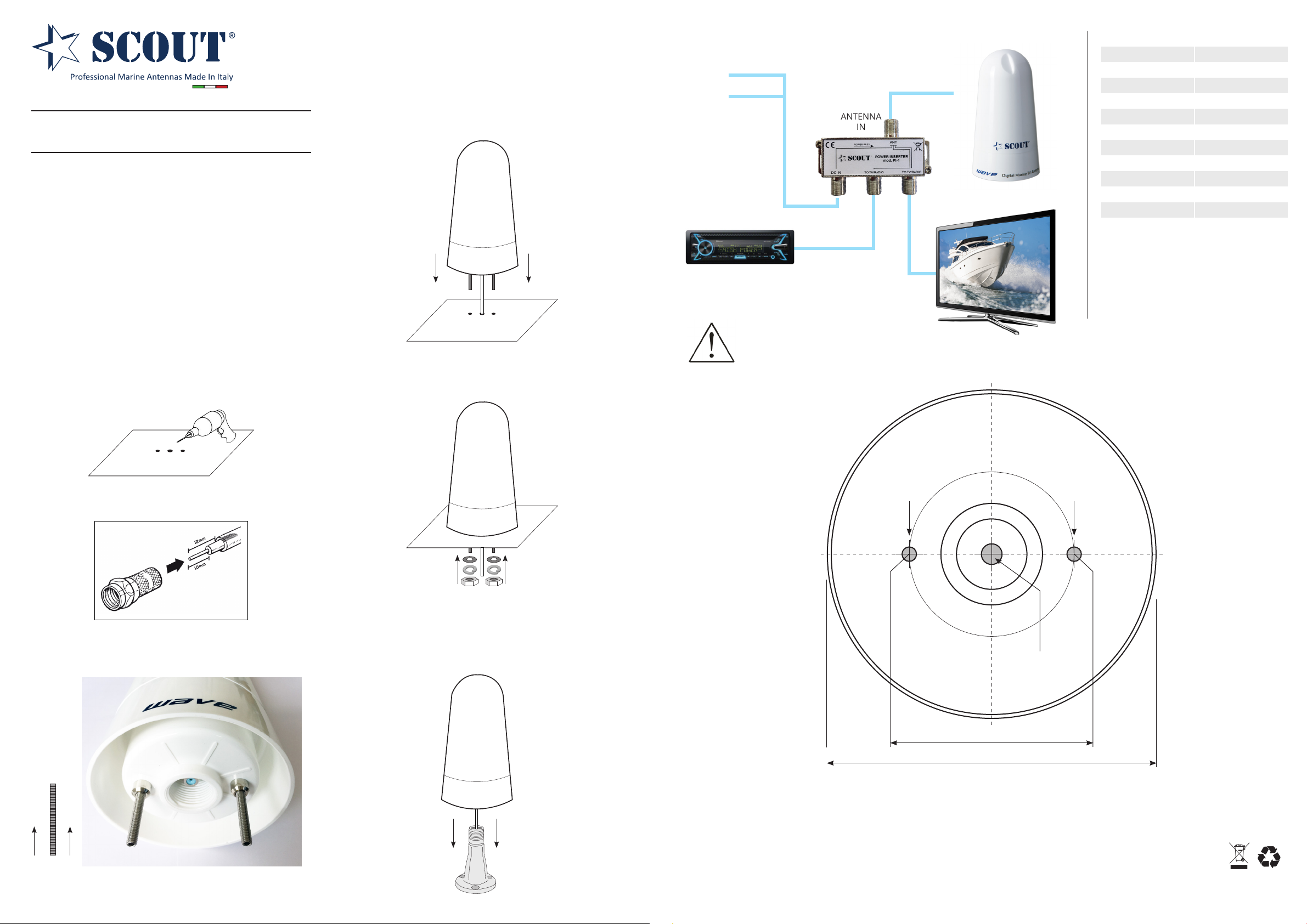
Installation type 1 - through-hole deck mounting
1 - Use the mounting template that you’ll nd at the end of this guide
to drill the three holes on the at surface where the antenna must
be mounted.
Mounting instructions
rev. 01/2023
4 - Connect the F male connector that you tted on the termination
of the coax cable to the F female connector on the bottom of the antenna, then set the antenna on the surface in a way that both screws
enter into the holes that you drilled earlier.
5 - Insert the washers and the nuts and secure the antenna on the
surface. The installation is now complete.
Wiring - Wire the antenna as shown in the picture below.
RED +
BLACK -
Coax cable 75 Ohm
10 m (33’)
ANTENNA
IN
12V fused power cable
TV/RADIO
OUT
Radio cable*
* Not supplied with the antenna.
To be purchased separately.
TV cable 1 m (3.3’)
ATTENTION - To avoid damaging the antenna amplier or splitter, connect the power only after having completed all the other
connections indicated above.
Wave mounting template
Do not install the antenna onto
a metal surface or enclosure.
TV/RADIO
OUT
Technical specications
Reception Omnidirectional
Frequency Range 40-790 MHz
Impedance 75 ohm
Channels 2-69
Gain 25 dB
Input power 12V DC
Noise gure <1.7 dB
Output 2
Connectors F
Antenna diameter 11 cm (4”)
Height 20 cm (8”)
Material UV resistant ASA
2 - Run the coax cable through the central hole and t the F male
connectors on both its terminations.
3 - Tighten the screws for approx 1 cm.
Installation type 2 - mounting on a mount 1” x 14 thread
1 - Connect the F male connector that you tted on the termination of
the coax cable to the F female connector on the bottom of the antenna, then set the antenna on the mount by screwing it. The installation
is now complete.
Drill hole,
5 mm (0.2 in)
diameter
Drill hole,
5 mm (0.2 in)
diameter
Drill hole,
7 mm (0.3 in)
diameter
Support
• Wave is guaranteed against defective parts or workmanship for 2 years from time of purchase. This excludes any malfunction caused by
improper use, accidental or malicious damage. This doesn’t aect your statutory rights.
• If you do experience a problem with the product contact Scout Customer Services on +39 059 8754474.
• All instructions and models are subject to change without prior notice.
• Please keep these instructions safe for future reference.
• Recycle packaging where facilities exist.
Scout S.r.l. Via Enrico Fermi 90 - 41010 Limidi di Soliera MO - Italy - VAT nr. IT03625890367
Tel. +39 059 8754474 - [email protected] - www.scoutantenne.com
53 mm (2.1 in) bolt circle diameter
106 mm (4.1 in) complete unit
Page 2
Wave Digital Marine TV Antenna
MOUNTING OPTIONS
FITTING ‘F’ CONNECTOR
Vari abl e S ignal Bo oster x 1
‘F’ to Coax ial F lyl ead x 1
12/ 24V fu sed p ower cable x 1
Scr ew x 2
A:
B:
C:
D:
A
B
PACK CONTENTS
D
E
F
No pictu re on T V
■ Che ck amp lif ier LE D is on
■ Che ck coa xia l c able connecti ons
■ Adju st ga in of am plifie r
■ TV or s et top b ox not tune d in
■ Poor r ecepti on ar ea
Pic tur e bre aks u p o r fre ezes
■ Adju st ga in of am plifie r
■ Poor r ecepti on
Pow er LED d oes n ot illum ina te when pow er is sw itched on
■ No power, chec k oth er devic es on sa me el ectric al ci rcuit
■ Fuse has b
low n
H
■ Helpline: +44 (0) 1553 811000
FAULT FINDING
2 YEAR GUARANTEE
A:
B:
C:
D:
E:
F:
G:
H
:
Wall fixing hole
On/off power switch
LED power indicator
Gain control knob
12/ 24V po wer i nput
Antenn a i nput
TV/ Radio ou tput
TV/ Radio ou tput
SAFETY WARNINGS
C
SPECIFICATIONS
1
/4”
Des ign ed for
con tin uou s use
Des ign ed for
ind oor use only
Thi s s ignal bo oster is g uara nteed again st de fec tive parts or
wor kma nsh ip for 2 year s fro m tim e of purchase. T his e xclude s any
mal fun cti on cause d b e imp roper us e, ac cident al or mali cious
dam age
or remo val o f t he ou ter c asi ng. Th is do es no t aff ect yo ur
sta tutory ri ght s.
TO
AER IAL
EXT RA TV/RA DIO
OUT PUT IF REQU IRED
POWE R CON NEC TIO N
RED +12/ 24V BL ACK 0 V
TO TV ‘ F’
COAX IAL
FLYLEAD
12/ 24V FU SED C ONN ECT ION
ON
1. Slid e pow er sw itch to right. LED indic ato r s hould no w be on.
2. Tur n g ain c ontrol knob cloc kwi se to in crease sign al st rength.
10m m
12m m
1
2
CONNECTION DIAGRAM
FITTING ‘F’ CONNECTOR
MOUNTING OPTIONS
OPERATION
Vari abl e S ignal Bo oster x 1
‘F’ to Coax ial F lyl ead x 1
12/ 24V fu sed p ower cable x 1
Scr ew x 2
Scr ew Ca p x 2
‘F’ Co nnecto r x 2
A:
B:
C:
D:
E:
F:
A
B
PACK CONTENTS
D
E
F
Ins tal lat ion in struc tio ns inside
No pictu re on T V
■ Che ck amp lif ier LE D is on
■ Che ck coa xia l c able connecti ons
■ Adju st ga in of am plifie r
■ TV or s et top b ox not tune d in
■ Poor r ecepti on ar ea
Pic tur e bre aks u p o r fre ezes
■ Adju st ga in of am plifie r
■ Poor r ecepti on
Pow er LED d oes n ot illum ina te when pow er is sw itched on
■ No power, chec k oth er devic es on sa me el ectric al ci rcuit
■ Fuse has b
low n
H
■ Helpline: +44 (0) 1553 811000
■ Email: cust_serv@maxview.co.uk
■ Visit: www.maxview.co.uk
Maxview Reserve the right to change
specifications without prior notice
FAULT FINDING
2 YEAR GUARANTEE
A:
B:
C:
D:
E:
F:
G:
H
:
Wall fixing hole
On/off power switch
LED power indicator
Gain control knob
12/ 24V po wer i nput
Antenn a i nput
TV/ Radio ou tput
TV/ Radio ou tput
SAFETY WARNINGS
C
SPECIFICATIONS
1
/4”
Des ign ed for
con tin uou s use
Des ign ed for
ind oor use only
Thi s s ignal bo oster is g uara nteed again st de fec tive parts or
wor kma nsh ip for 2 year s fro m tim e of purchase. T his e xclude s any
mal fun cti on cause d b e imp roper us e, ac cident al or mali cious
dam age
or remo val o f t he ou ter c asi ng. Th is do es no t aff ect yo ur
sta tutory ri ght s.
TO
AER IAL
EXT RA TV/RA DIO
OUT PUT IF REQU IRED
POWE R CON NEC TIO N
RED +12/ 24V BL ACK 0 V
TO TV ‘ F’
COAX IAL
FLYLEAD
12/ 24V FU SED C ONN ECT ION
ON
1. Slid e pow er sw itch to right. LED indic ato r s hould no w be on.
2. Tur n g ain c ontrol knob cloc kwi se to in crease sign al st rength.
10m m
12m m
1
2
CONNECTION DIAGRAM
FITTING ‘F’ CONNECTOR
MOUNTING OPTIONS
OPERATION
Codice: PF AN NTV002
ITA
L’installazione dell’antenna deve procedere seguendo le presenti
istruzioni per assicurarne la massima performance.
• Installare l’antenna in una posizione con visuale totalmente
aperta dell’orizzonte e il più in alto possibile.
• Mantenere la visuale dell’antenna libera da ostacoli.
• Il piano dove eettuare l’installazione deve essere il più rigido
possibile e non soggetto a eccessive vibrazioni. L’oscillazione
dell’antenna può essere minimizzata montandola al centro
dell’imbarcazione. Evitare il montaggio in posizioni periferiche
dove il movimento oscillatorio è maggiore.
• In caso di installazione a lo evitare di posizionare l’antenna su
una supercie metallica.
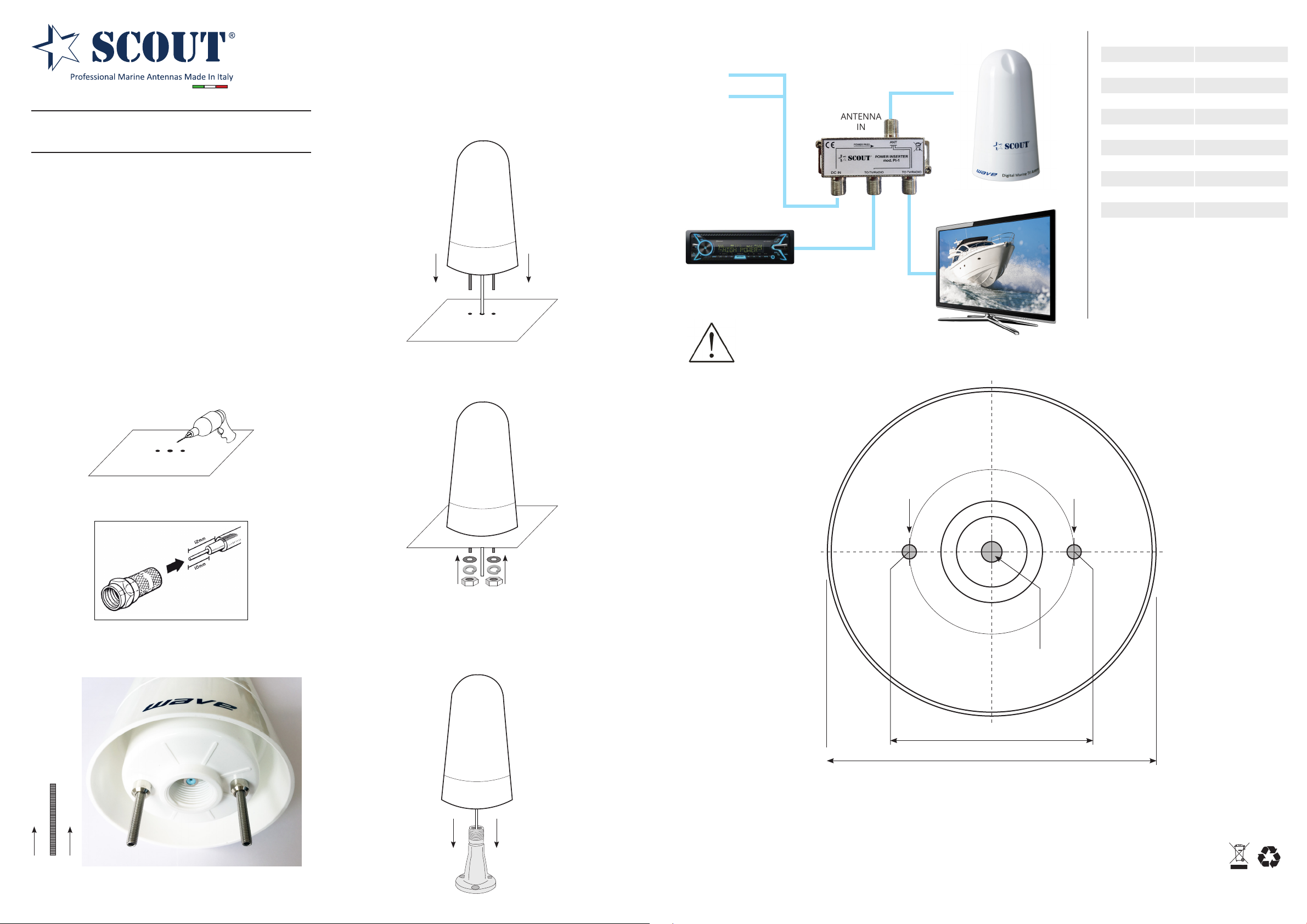
Installazione tipo 1 - montaggio su supercie piana
1 - Utilizzate la dima di foratura che trovate alla ne di questa guida
per operare i tre fori sulla supercie piana sulla quale volete instal-
lare l’antenna.
Istruzioni di montaggio
rev. 01/2023
4 - Avvitate il connettore F maschio presente all’estremità del cavo al
connettore F femmina presente nel basamento dell’antenna, quindi
posizionate l’antenna sulla supercie in modo che le viti entrino nei
due fori creati in precedenza.
5 - Inserite le rondelle e i dadi per ssare l’antenna sul piano di montaggio. L’installazione è completata.
Collegamento - Collegare l’antenna seguendo lo schema sotto riportato.
ROSSO +
NERO -
Cavo coassiale
75 Ohm 10 m
ANTENNA
IN
cavo alimentazione 12V
TV/RADIO
OUT
TV/RADIO
OUT
Cavo radio*
* Non fornito con l’antenna.
Da acquistare separatamente.
Cavo TV 1 m
ATTENZIONE - Per evitare il danneggiamento dell’amplicatore dell’antenna o dello splitter procedere al collegamento della
corrente solo dopo avere ultimato tutti gli altri collegamenti sopra indicati.
Dima di installazione Wave
Non installare l’antenna su una
supercie metallica.
Speciche tecniche
Ricezione Omnidirezionale
Frequenza 40-790 MHz
Impedenza 75 ohm
Canali 2-69
Guadagno 25 dB
Input power 12V DC
Cifra di rumore <1.7 dB
Uscite 2
Connettori F
Diametro antenna 11 cm
Altezza 20 cm
Materiale ASA con ltro UV
2 - Fate scorrere il cavo coassiale attraverso il foro centrale e montate
i connettori F su entrambe le estremità.
3 - Avvitate le viti nei due fori di montaggio presenti nel basamento
dell’antenna, avvitandoli per circa 1 cm.
Installazione tipo 2 - montaggio su base 1” x 14 letti
1 - Avvitate il connettore F maschio presente all’estremità del cavo al
connettore F femmina presente nel basamento dell’antenna, quindi
posizionate l’antenna sulla base avvitandola. L’installazione è completata.
Forare
5 mm
Forare
5 mm
Forare
7 mm
Supporto
• Wave è garantita per 2 anni da difetti di fabbricazione in termini di materiale e lavorazione dal momento dell’acquisto. La
garanzia esclude ogni malfunzionamento derivante da uso improprio o accidentale dell’oggetto.
• In caso di problema tecnico potete contattate il servizio clienti di Scout al numero +39 059 8754474.
• Le speciche tecniche qui contenute possono variare a discrezione del produttore.
• Conservare le presenti istruzioni per consultazioni future.
• A ne vita non gettare questo apparecchio nella normale raccolta dei riuti, ma portalo presso dei punti di raccolta
autorizzati. In questo modo contribuirai a preservare l’ambiente.
Scout S.r.l. Via Enrico Fermi 90 - 41010 Limidi di Soliera MO - Italy - VAT nr. IT03625890367
Tel. +39 059 8754474 - [email protected] - www.scoutantenne.com
53 mm
106 mm
 Loading...