

Scott TC Shock,Equalizer TC Shock Owner's Manual
CONFORME AUX EXIGENCES DE SECURITE - NF R30-020
T
OWNERS MANUAL
BEDIENUNGSANLEITUNG
MANUEL D’UTILISATION
BIKE
OWNERS
MANUAL
2007
©2005 Sc
ott Sports SA – all rights r
eserv
ed
WWW.SCOTT-SPORTS.COM
Scott Sports SA
Route du Crochet 17
1762 Givisiez / Switzerland
www
.sc
ott-sports.c
om
«SAG-BOY»
The length of the grey beam shows the optimum eye-to-eye distance of the rear shocks.
Der graue Balken zeigt den optimalen Bolzenabstand des Dämpfers.
La longueur de la barre grise représente l’écart optimal entre les points de fixation
de l’amortisseur.
EQUALIZER TC SHOCK

ENGLISH
01
00
CONTENT
DEUTSCH
FRANÇAIS
> Traction Control-Functions P. 02
> Power Stabilizer P. 02
> Intelligent Rebound Valve P. 03
> Oil Transfer Shock P. 03
> Picture of the Equalizer TC Shock
and Remote Control Lever P. 04
> Basic Set-Up of the Remote
Control Equalizer TC Shock P. 05
> Mount of the remote control of P. 05
Equalizer TC Shock
> Recommended Tools for the
Shock Set-Up P. 06
> Set-Up of Positive Air Chamber
Equalizer TC Shock P. 07
> Set-Up of Negative Air Chamber
Equalizer TC Shock P. 07
> Set-Up of Rebound Equalizer TC Shock P. 08
> More Details about Shock Set-Up
Equalizer TC Shock P. 09
> Maintenance / Service Guide P. 09
> Warranty P. 12/13
CONTENT
The basic set-up of a Scott Equalizer TC Shock is easy
and can be done within a few minutes.
The Scott Equalizer TC Shock should be adjusted exactly
to the current rider for reaching maximum safety and
fun while riding.
All adjustments should be done at the local dealer
or following this manual.
ENGLISH
03
02
DEUTSCH
FRANÇAIS
The heart of the TC-System is the newly developed
and innovative Scott Equalizer TC Shock, offering three
functions which make this system possible.
By using the remote lever you can choose between following functions:
1. ALL TRAVEL MODE: full travel of 165mm
2. TRACTION MODE: by reducing the chamber volume
inside the shock the travel of the shock will be reduced
to around 60% (approx. 100mm), the characteristic of
the air spring gets harder. This results in climbing
without “bobbing” and offers still optimum traction of
the rear wheel.
3. LOCK OUT MODE: the shock is locked, climbing on
asphalt roads is now possible without any power loss.
Simultaneously a blow-off-system prevents the shock
being damaged in case the rider did not open the system while crossing obstacles.
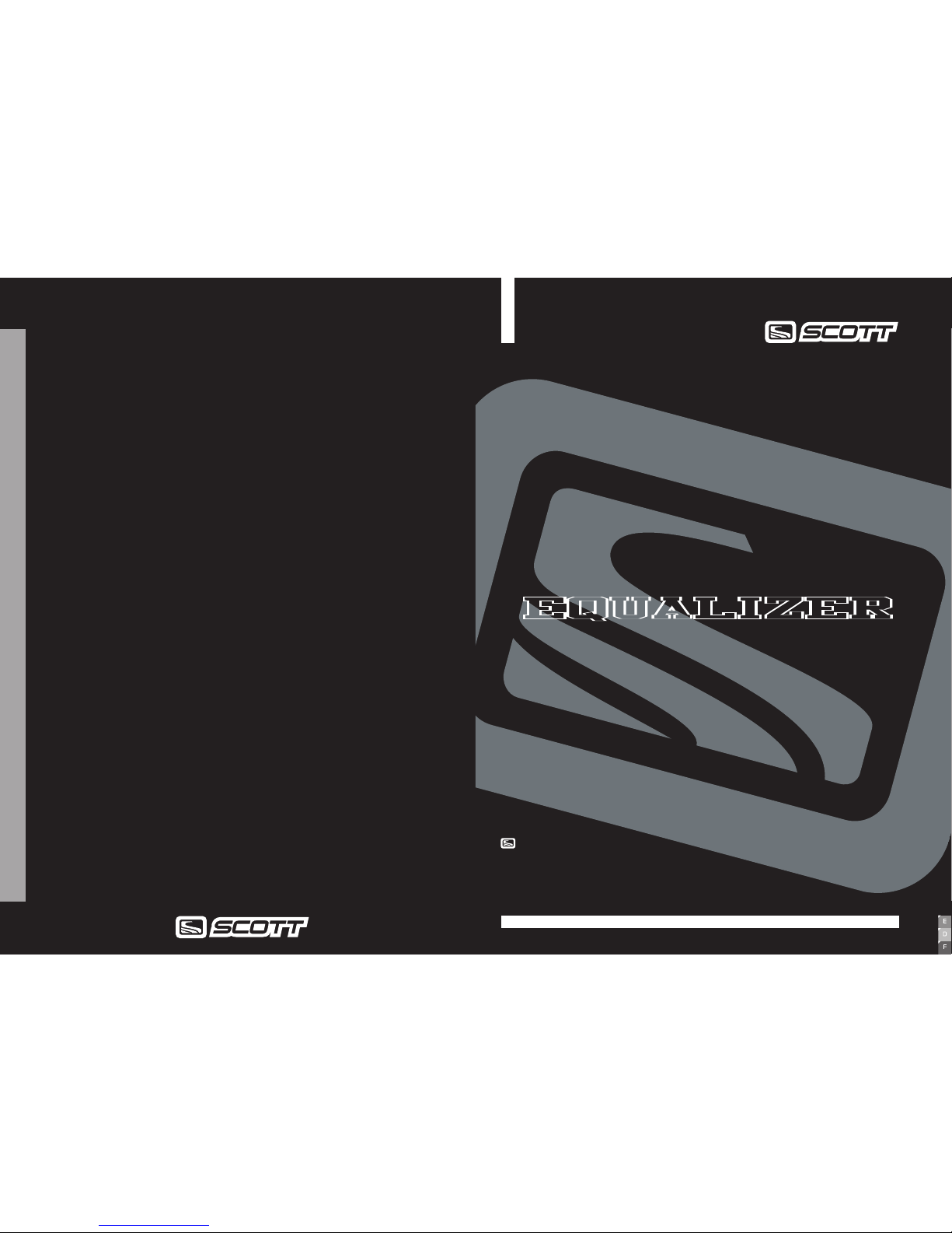
You will find following positions on the remote lever.
[1]
TRACTION CONTROLFUNCTIONS INTELLIGENT REBOUND VALVE OIL TRANSFER SHOCK
In contrary to conventional systems which have the
piston with compression and rebound shim stack
moving in an oil bath, our new developed OTS-system pushes the oil through a fixed piston from one
oil chamber to another.
By using this fixed piston Scott was able to integrate more functions (e.g. Power Stabilizer,
Intelligent Rebound Valve) beside the standard
compression/ rebound adjustment devices.
In addition the shock works with a bigger volume
of oil which results in a bigger heat resistance
and a reduced wear and tear of the oil.
Scott found a revolutionary way to design a valve that
adjusts itself by the speed of impact on the rebound
motion.
In contrary to conventional systems our new designed
Intelligent Rebound Valve system can distinguish
if the shock should rebound fast or slow.
On small impacts the system stays fully active and
reacts with a fast rebound.
After a jump or big impacts/grooves the rebound is
slowed down automatically. Doing so, the kick back of
the saddle that results from too fast rebound, is eliminated.
1
remote lever
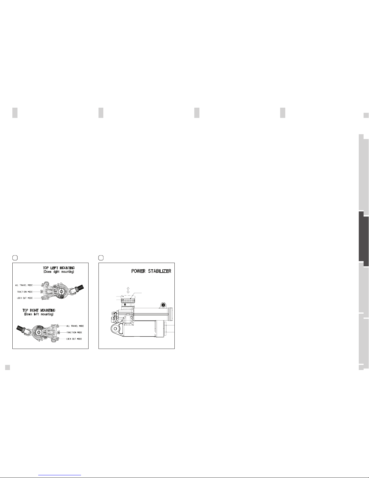
The Power Stabilizer is a option to ride with or
without Pedal Platform by just tapping one button on
the shock.
By pulling the rebound adjuster knob upward you
switch off the pedal platform for a supple break
away.
By pushing the rebound adjuster knob downward you
switch on the pedal platform for a better climbing
without bobbing when standing on the pedals. [2]
2
PowerSt abilizer OFF
PowerSt abilizer ON
PUSH / PULL
ADJUSTER KNOB
rebound knob/ps knob

ENGLISH
05
04
DEUTSCH
FRANÇAIS
In the drawing of the shock and remote lever, shown
below, you will see the parts indicated with numbers
which will be used in the manual for the adjustment
and set-up.
EQUALIZER TC SHOCK AND
REMOTE CONTROL LEVER
BASIC SET-UP OF THE REMOTE
CONTROL OF EQUALIZER
TC SHOCK
1. Put the remote lever (L1) to position “lock-out”
2. Fix the remote control cable (L2) with the cable fixation screw (S9) using a 3mm allen key (tightening
torque: 3 Nm) on the Mode Lever (S12)
3. Put the remote lever now to position “Traction Mode”
The Lock Out Pin (S11) should be pulled out approx.
1mm.
4. When putting now the remote lever to position “All
Travel” the cable will pull the Mode Lever (S12) including the Traction Mode Pin (S10) and the shock will
offer now the full travel.
5. Check now the set-up for perfect function of remote
lever and shock
6. In case you want to fine-tune the brake-away power
of the remote lever, you can do this by using a 2mm
allen key and by turning the allen screw (L4). In case
you want to readjust the tension of the remote control
cable you can do this by using the tension screw (L3).
[1]
S1 Upper Shock Bolt
S2 Lower Shock Bolt
S3 Left Piggy-Back
S4 Right Piggy-Back
S5 Shock Piston
S6 Rebound Adjuster/Power Stabilizer Knob
S7 Positive Chamber Valve
S8
Negative Chamber V
alve
S9 Remote Cable Fixation Screw
S10 Traction Mode Pin
S11 Lock Out Pin
S12 Mode Lever
L1 Remote Lever
L2 Remote Control Cable
L3 Tension Screw
L4 Allen Screw
L5
Allen Screw
L6 Cable Guide Hanger
1
MOUNT OF THE
REMOTE CONTROL
OF EQUALIZER TC SHOCK
To switch the TC2 Lever from one side of the bar to the
other one, please proceed as explained below:
[2] [3]
1. Remove the inner cable from the system as shown
in the Equalizer TC manual
2. Unscrew the clamp fixing screw on the bar clamp
with a 3 mm Allen key
3. Unscrew screw L1 by using a 3mm Allen key
4. Take the cable guide assembly (L2 + L3 + L4) away
5. Unscrew screw L5 with a 2 mm allen key
6. Unscrew the main screw L8 with a 4 mm allen key
7. Lift parts L8, L9 (2x) and L10 . Take the spri ng L6
and the ball L7 out of the assembly. Pay attention not
to loose them.
8. Remove screw L12 with 1.5mm allen key
9. Loosen base plate fixing screw L11 with a 3 mm
allen key
10. Turn index plate L13 to the position of your choice
(turn it of 180° for left or right position ), see detail
pictures.
2
 Loading...