

Scott Spark,Spark 2014 Owner's Manual
SPARK
N
SCOTT 2014
BIKE OWNER’S
MANUAL
SCOTT SP ORTS SA | 17 RTE DU CROC HET | 1762 GIVIS IEZ | SWITZERL AND
© 2013 SCOTT S PORTS SA, ALL R IGHTS RESERV ED | SCOTT-SPORTS .COM
DISTRIBUTION: SSG (EUROPE) DISTRIBUTION CENTER SA
P.E.D ZON E C1, RUE DU KIE LL 60 | 6790 AUBANG E | BELGIUM | V3 .2/201307 10
SPARK
2 scott-sports.com 3
BIKE OWNER’S MANUAL
ENGLISH
CONTENT
The Spark should be adjusted exactly to the individual
rider to achieve maximum safety and fun while riding.
All adjustments should be done at a local SCOTT dealer
or by strictly following this manual.
In order to avoid any harm or in the case of technical
problems or doubts please contact your authorized
SCOTT dealer.
Spark Concept ..................................................................P.004
Geometry/Technical Data Spark 27.5”/650B .....................................P.005
Geometry/Technical Data Spark 29” .............................................P.006
TC Shock Technology/TWINLOC Levers .........................................P.0 07
Basic Set-Up of the TWINLOC Remote Control .................................. P.01 4
Recommended Tools for the Shock Set-Up .......................................P.0 1 8
Set-Up Spark with FOX Nude Shock .............................................P. 019
Spark Cable Routing .............................................................P.028
Adjustment of Seatpost-Height ..................................................P. 03 4
Replaceable Drop Out Systems ..................................................P.0 3 4
Front Fork Set-Up/Change of Front Fork ........................................P.03 7
Pivot Maintenance ...............................................................P.03 7
Warranty ........................................................................P. 03 8
SPARK
4 scott-sports.com 5
BIKE OWNER’S MANUAL
ENGLISH
SPARK CONCEPT
The new Spark is the result of 2 years of research and development for one of the
lightest mountain bike frame set available on the market, hitting the scale at below
1800 grams (4 lbs) including the frame, FOX Nude shock and the unique TWINLOC
remote control.
SCOTT’s focus was not only on lightweight but also on a durable and stiff frame with
an innovative suspension technology in combination with an optimized kinematics of
the rear swingarm.
The combination of an optimized kinematics with an extraordinary suspension
technology closes the gap between superlight hardtail bikes (e.g. SCOTT Scale) and
the new generation of marathon/trail bikes (e.g. SCOTT Genius).
Spark was designed for riders looking for a dual suspended race and marathon bike
offering a maximum rear wheel travel of 120mm (27.5”)/100mm (29”).
SCOTT does not see frame and rear shock as single components which are assembled
together on a bike, but as a concept with all these components working together and
offering an outrageous function by matching perfectly.
The Spark Concept is based on a multi-pivot technology.
The damping performance was improved in comparison to the already famous
“old” Spark, and with reworking also the kinematics we were able to reach a better
progression in the end of the stroke/travel of the swingarm.
The SCOTT system, named TC (Traction Control) will allow you to reduce by remote
control the rear wheel travel from 120 (27.5”)/100 (29”)mm to 85 (27.5”)/70(29”)mm
including a more progressive spring rate but still offering a supple break away.
No power will be lost and an optimum power transfer is guaranteed as the swingarm,
in contrary to locked or automatic-locking systems, can follow the trail surface and will
offer perfect traction and higher speed while standing on the pedals.
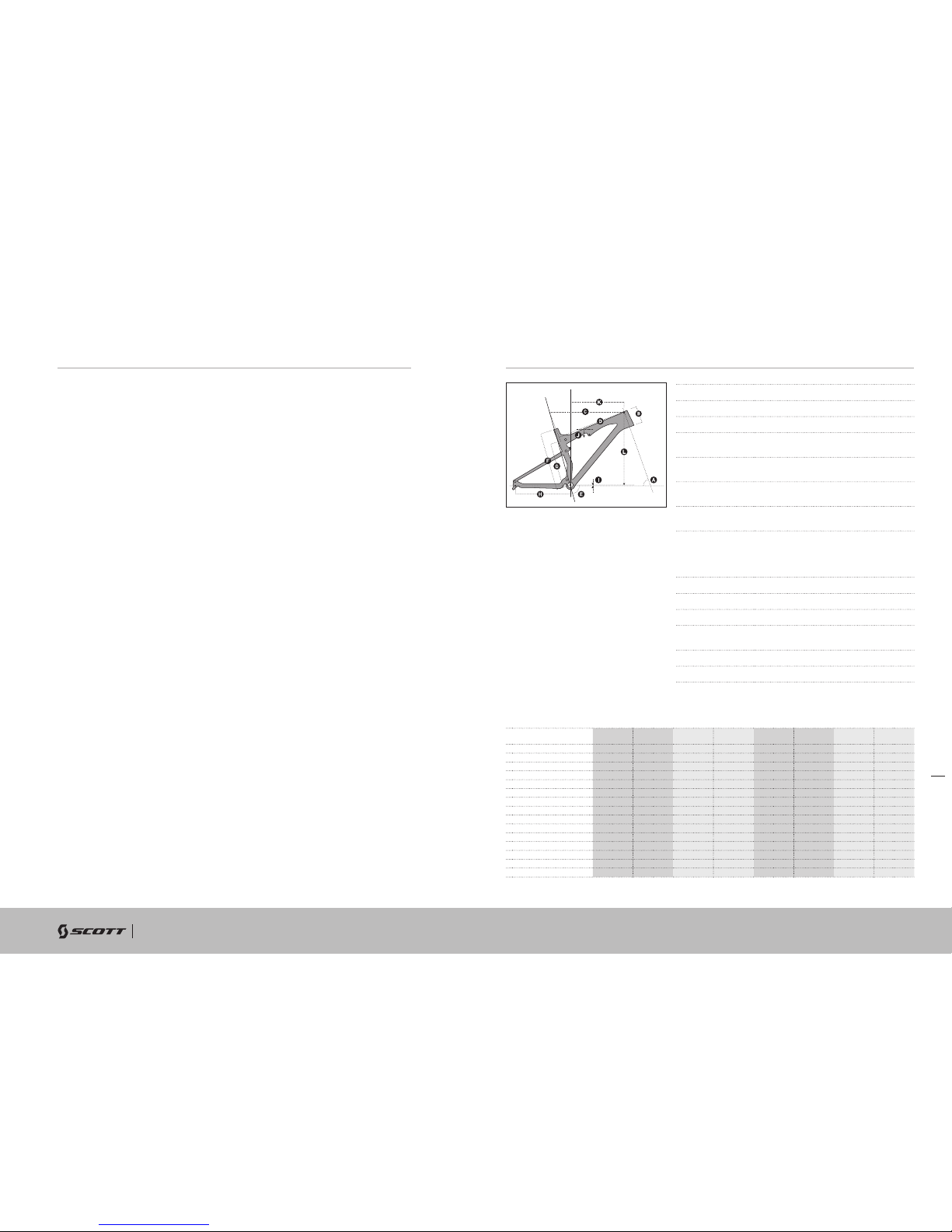
GEOMETRY/TECHNICAL DATA SPARK 27.5”/650B
SPARK 27.5”/650B
Tra ve l 120/85/0mm
Suspension Ratio 2.40
Piston stroke 50mm
Shock length
(Eye to Eye)
190mm
Hardware
Mainframe
22,2mm x 8mm
Hardware
Swingarm
22.2mm x 8mm
Seatpost
diameter
31.6mm
Headset semi integr. for tapered 1 1/8-1.5
(44/54.9mm inner diameter
of frame) or with 1 1/8 straight
(44.0mm)
Fork travel 120mm
Fork length 507mm
BB housing BB PF 92 carbon / 73mm alloy
Front derailleur Shimano E-Type / SRAM S3 direct
mount
Bearings 2 x IGUS, 6 x 6802 (24x15x5)
Max. tire width 57mm/2.25”
S
HIGH BB SettInG
S
LOW BB SettInG
M
HIGH BB SettInG
M
LOW BB SettInG
L
HIGH BB SettInG
L
LOW BB SettInG
XL
HIGH BB SettInG
XL
LOW BB SettInG
AHEAD TUBE ANGLE 68.7° 68.0° 68.7° 68.0° 68.7° 68.0° 68.7° 68.0°
B HEADTUBE LENGTH 110mm 4.3in 110mm 4.3in 120mm 4.7in 120mm 4.7in 140mm 5.5in 140mm 5.5in 160mm 6.3in 160mm 6.3in
C TOPTUBE LENGTH HORIZONTAL 553mm 21.8in 555mm 21.9in 589mm 23.2in 590mm 23.2in 618mm 24.3in 620mm 24.4in 648mm 25.5in 650mm 25.6in
DTOPTUBE LENGTH ACTUAL 509mm 20.0in 509mm 20.0in 540mm 21.3in 540mm 21.3in 570mm 22.4in 570mm 22.4in 602mm 23.7in 602mm 23.7in
E SEAT TUBE ANGLE 74.2° 73.5° 74.2° 73.5° 74.2° 73.5° 74.2° 73.5°
F BB CENTER TO TOP OF SEATTUBE 400mm 15.7in 400mm 15.7in 450mm 17.7in 450mm 17.7in 490mm 19.3in 490mm 19.3in 540mm 21.3in 540mm 21.3in
GBB CENTER TO TOPTUBE CENTER 331mm 13.0in 331mm 13.0in 347mm 13.7in 347mm 13.7in 395mm 15.6in 395mm 15.6in 435mm 17.1in 435mm 17.1in
HCHAINSTAY LENGTH 420mm 16.5in 420mm 16.5in 420mm 16.5in 420mm 16.5in 420mm 16.5in 420mm 16.5in 420mm 16.5in 420mm 16.5in
I BB OFFSET 2mm 0.1in -8mm -0.3in 2mm 0.1in -8mm -0.3in 2mm 0.1in -8mm -0.3in 2mm 0.1in -8mm -0.3in
BB HEIGHT 342mm 13.5in 332mm 13.1in 342mm 13.5in 332mm 13.1in 342mm 13.5in 332mm 13.1in 342mm 13.5in 332mm 13.1in
J STANDOVER HEIGHT 757mm 29.8in 753mm 29.6in 767mm 30.2in 763mm 30.0in 804mm 31.7in 800mm 31.5in 835mm 32.9in 830mm 32.7in
WHEELBASE
1072mm 42.2in 1073mm 42.2in
1108mm 43.6in 1109mm 43.7in 1140mm 44.9in 1141mm 44.9in 1172mm 46.1in 1173mm 46.2in
K REACH 397mm 15.6in 391mm 15.4in 429mm 16.9in 423mm 16.7in 453mm 17.8in 448mm 17.6in 478mm 18.8in 473mm 18.6in
L STAC K 552mm 21.7in 556mm 21.9in 561mm 22.1in 565mm 22.2in 579mm 22.8in 583mm 23.0in 598mm 23.5in 602mm 23.7in
STEM LENGTH 70mm 70mm 80mm 80mm 90mm 90mm 100mm 100mm
SPARK
6 scott-sports.com 7
BIKE OWNER’S MANUAL
ENGLISH
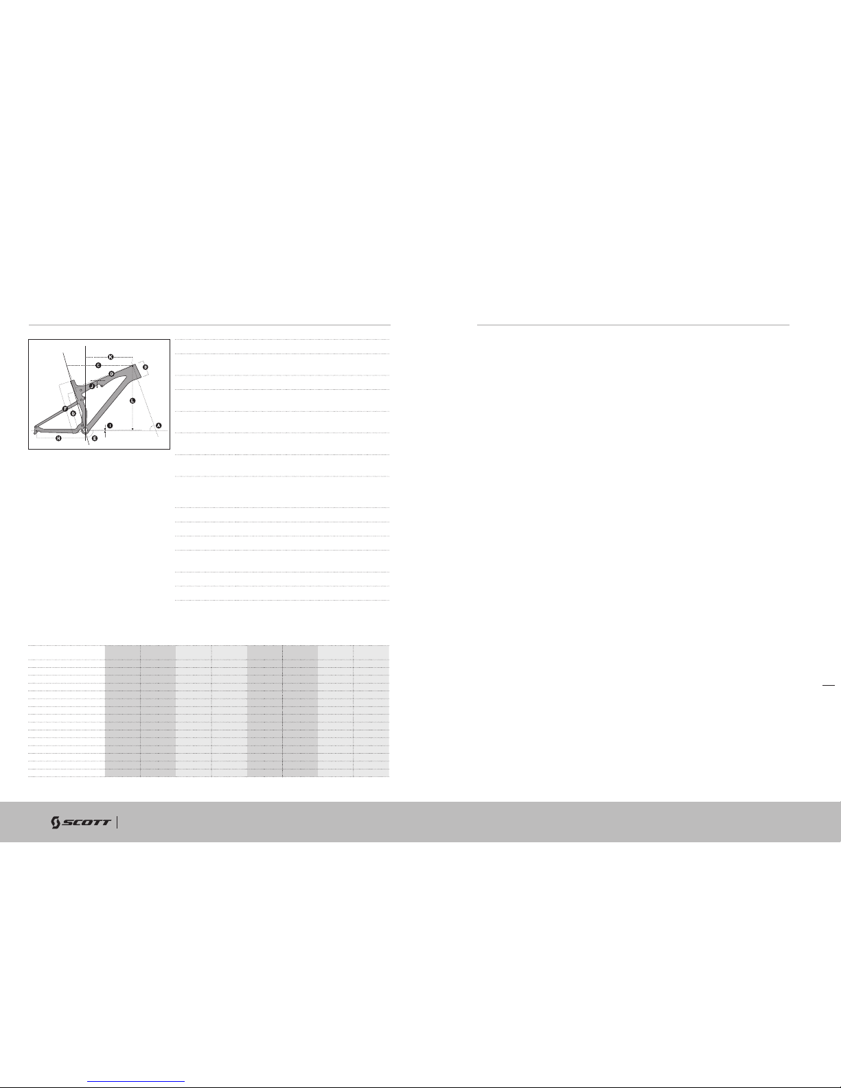
GEOMETRY/TECHNICAL DATA SPARK 29“
Tra ve l 100/70/0mm
Suspension
Ratio
2.63
Piston stroke 38mm
Shock length
(Eye to Eye)
165mm
Hardware
Mainframe
22,2mm x 8mm
Hardware
Swingarm
22.2mm x 8mm
Seatpost
diameter
31.6mm
Headset semi integr. for tapered 1 1/8-1.5
(44/54.9mm inner diameter of frame) or
with 1 1/8 straight (44.0mm)
Fork travel 100mm
Fork length 506mm
BB housing BB PF 92 carbon / 73mm alloy
Front
derailleur
Shimano E-Type / SRAM S3 direct
mount
Bearings 2 x IGUS, 6 x 6802 (24x15x5)
Max. tire width 57mm/2.25”
SPARK 29"
SHOCK TECHNOLOGY
The heart of the TC-System is the FOX Nude Shock, offering three functions which
make this system possible.
The TWINLOC remote control lever is the evolution of the already outstanding
TRACLOC system of SCOTT.
While TRACLOC allowed only the change on the SCOTT TC rear shocks between
the SCOTT patented climb, traction and full-mode on the fly from the handlebar,
the TWINLOC allows also the remote control of the front fork to shift between lockout and open mode at the same time when you change the modes on the SCOTT
rear shox.
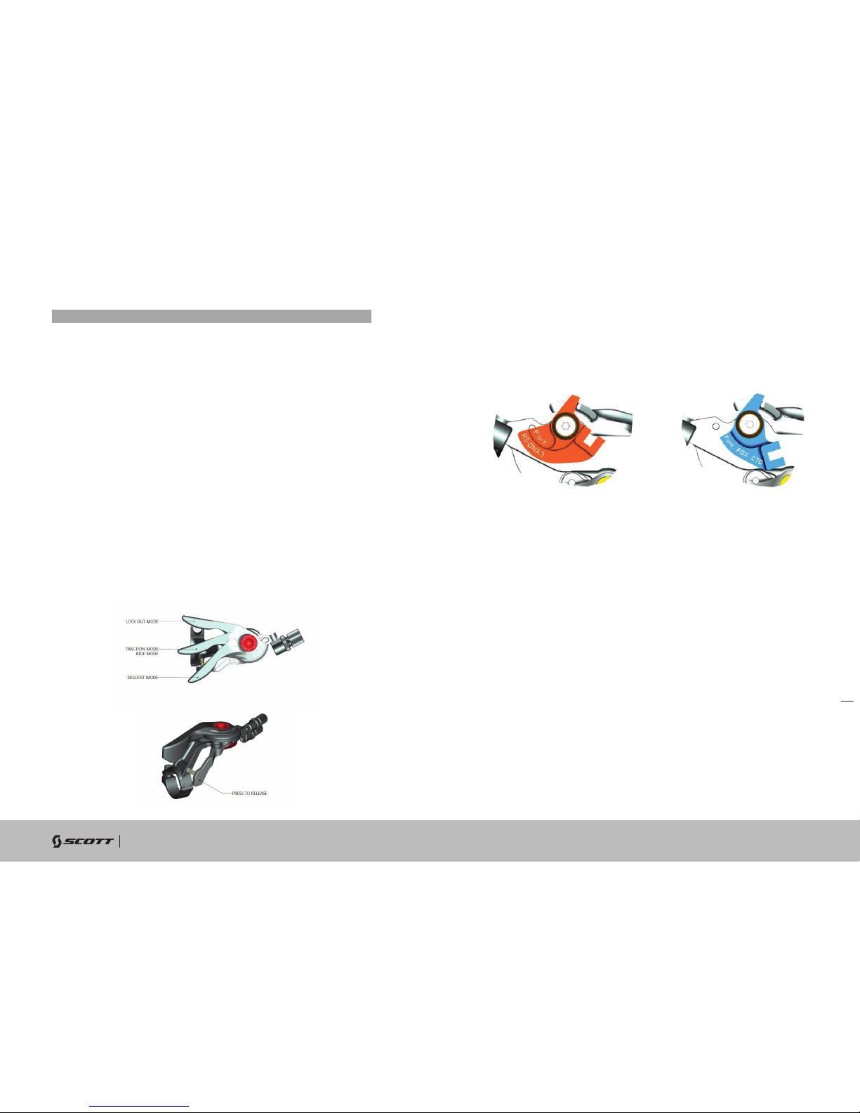
In combination with SRAM/RockShox DNA 3 or FOX CTD forks it is also possible to
have a traction mode on the fork.
The 3 modes of CTCD in combination with FOX Nude are:
- CLIMB-OUT MODE: Climb rear, climb front
- TRACTION MODE: Traction mode rear, (incl. geometr y change and
reduced travel), platform mod e front
- DESCENT MODE: Full travel rear, full travel front
The 3 modes of CTD in combination with FOX CTD are:
- CLIMB-OUT MODE: Climb rear, climb front
- RIDE MODE: Platform(ride)mode rear, platform mode front
- DESCENT MODE: Full travel rear, full travel front
Therefore SCOTT offers 2 different TWINLOC levers with following fork/rear shock
combinations:
- FOX Nude with differe nt rolls for FOX CTD fo rk and RockShox DNA 3 fork
(SCOTT Article number: 230097)
- FOX CTD with different rolls for FOX C TD fork and RockShox DNA 3 fork
(SCOTT Article number: 230098)
Please note that the FOX CTD rear shock does not offer a traction mode, but a ride
mode, featuring a platform. In contrary to FOX Nude the air chamber volume of the
positive chamber remains the same throughout the different modes.
S
HIGH BB SettInG
S
LOW BB SettInG
M
HIGH BB SettInG
M
LOW BB SettInG
L
HIGH BB SettInG
L
LOW BB SettInG
XL
HIGH BB SettInG
XL
LOW BB SettInG
AHEAD TUBE ANGLE 70.1° 69.5° 70.1° 69.5° 70.1° 69.5° 70.1° 69.5°
B HEADTUBE LENGTH 105mm 4.1in 105mm 4.1in 105mm 4.1in 105mm 4.1in 115mm 4.5in 115mm 4.5in 125mm 4.9in 125mm 4.9in
C TOPTUBE LENGTH HORIZONTAL 568mm 22.4in 570mm 22.4in 598mm 23.5in 600mm 23.6in 628mm 24.7in 630mm 24.8in 649mm 25.6in 650mm 25.6in
DTOPTUBE LENGTH ACTUAL 518mm 20.4in 518mm 20.4in 539mm 21.2in 539mm 21.2in 566mm 22.3in 566mm 22.3in 588mm 23.1in 588mm 23.1in
E SEAT TUBE ANGLE 73.1° 72.5° 73.1° 72.5° 73.1° 72.5° 73.1° 72.5°
F BB CENTER TO TOP OF SEATTUBE 400mm 15.7in 400mm 15.7in 440mm 17.3in 440mm 17.3in 481mm 18.9in 481mm 18.9in 541mm 21.3in 541mm 21.3in
GBB CENTER TO TOPTUBE CENTER 335mm 13.2in 335mm 13.2in 350mm 13.8in 350mm 13.8in 403mm 15.9in 403mm 15.9in 448mm 17.6in 448mm 17.6in
HCHAINSTAY LENGTH 448mm 17.6in 448mm 17.6in 448mm 17.6in 448mm 17.6in 448mm 17.6in 448mm 17.6in 448mm 17.6in 448mm 17.6in
I BB OFFSET -41mm -1.6in -48mm -1.9in -41mm -1.6in -48mm -1.9in -41mm -1.6in -48mm -1.9in -41mm -1.6in -48mm -1.9in
BB HEIGHT 324mm 12.8in 317mm 12.5in 324mm 12.8in 317mm 12.5in 324mm 12.8in 317mm 12.5in 324mm 12.8in 317mm 12.5in
J STANDOVER HEIGHT 762mm 30.0in 758mm 29.8in 768mm 30.2in 764mm 30.1in 806mm 31.7in 802mm 31.6in 836mm 32.9in 833mm 32.8in
WHEELBASE
1082mm 42.6in 1082mm 42.6in
1112mm 43.8in 1112mm 43.8in 1143mm 45.0in 1143mm 45.0in 1163mm 45.8in 1163mm 45.8in
K REACH 386mm 15.2in 379mm 14.9in 416mm 16.4in 409mm 16.1in 442mm 17.4in 436mm 17.2in 456mm 18.0in 453mm 17.8in
L STAC K 602mm 23.7in 606mm 23.9in 602mm 23.7in 606mm 23.9in 611mm 24.1in 615mm 24.2in 623mm 24.5in 625mm 24.6in
STEM LENGTH 70mm 70mm 80mm 80mm 90mm 90mm 100mm 100mm
SPARK
8 scott-sports.com 9
BIKE OWNER’S MANUAL
ENGLISH
You have 3 positions of the TWINLOC remote lever.
1. CLIMB MODE:
The shock is nearly locked; climbing on asphalt roads is now possible without any
power loss. Simultaneous a blow-off-system prevents the shock being damaged in
case the rider did not open the system while crossing obstacles.
2. TRACTION MODE/RIDE MODE:
For Traction: by reducing the internal chamber volume inside the shock the travel of
the shock will be reduced to around 80% (approx. 96/80mm) the characteristic of
the air spring gets harder, the SAG is shorter and the geometry steeper. This results
in climbing without “bobbing” and offers still optimum traction of the rear wheel.
For Ride: by adding a platform o n the compression dampin g system the shock will
not bounce while standing on the peda ls.
3. DESCENT MODE:
Full travel of 120/100mm (27.5”/29”)
You will find the following positions on the remote lever:
IMPORTANT:
You can only assemble the TWINLOC remote lever in “left side upward position” on
the handlebar.
For the assembly of the remote control of the front fork lock-out 2 different cable rolls
which are changeable are existing.
The different roll for the pull of the fork remote cable can be changed within few
minutes to adapt the lever to your fork model/brand.
You will see on the downside of the roll the indication of the fork brand or the fork
model.
Scott offers 2 different TWINLOC levers with following fork/rear shock combinations:
- FOX Nude with different rolls for FOX CTD fork and RockShox DNA 3 fork
(Scott Article number: 230097)
- FOX CTD with different rolls for FOX CTD fork and RockShox DNA 3 fork
(Scott Article number: 230098)
Please kindly note that the cable roll of a RockShox DNA3 or FOX CTD fork-lever is
not interchangeable with the regular rolls of 2 step forks. You need to use another
lever!
For details on this please contact your authorized Scott dealer.

SPARK
10 scott-sports.com 11
BIKE OWNER’S MANUAL
3
2
FORK CABLE
ENGLISH
To change the rolls to match another fork brand please follow the diagrams below:
ROLL FORK MOUNTING
ROLL FORK UNMOUNTING
ASSEMBLY OF THE REMOTE CABLE
SRAM/ROCKSHOX FORKS:
IMPORTANT:
Please make sure the lockout of SRAM/RockShox or FOX fork is activated after
transport correctly. Therefore please compress fork 5-10 times before following the
manual on remote cable installation and adjustment.
The lever should show on the downside of the cable roll the brand name of the fork
you are going to use. Please do not try to use a RockShox roll with a FOX fork or vice
versa.
To assemble the cable please bring the lever into the Descent Mode, push the cable
into the lever-eyelet as shown on drawing below, push it through the pre-cut cable
housing and fix it at the assembly unit on top of the right side of the fork crown.
Fix the cable with the 2mm allen screw on the barrel adjuster on the fork crown
with a tightening torque of 0.9Nm/8 lb/in, cut the cable and secure it with a cable
end-cap. Please refer for this action also to the manual of SRAM/RockShox or FOX
attached to the bike.
TIP:
To check for accurate cable tension, please try to move the
plastic end cap of the cable housing at the barrel adjuster
on the remote lever. There should be “no-play” between
cap and barrel adjuster.
In case of “play” please turn the barrel adjuster clockwise
until “no-play”.
Fork cable
2mm allen
Rock Shox
Fork
 Loading...