

Page 1
WWW.SCOTT-SPORTS.COM
WWW.SCOTT-SPORTS. COM
SCOTT Spor ts SA
Route du Crochet 17, CH–1762 Givisiez
Phone: +41 26 460 16 16 | Fax: +41 26 460 16 00
Email: scottsupport@scott-sports.com
All rights r eserved © 2016 S COTT Sports SA
Distribution:
SSG (Europ e) Distribution Ce nter SA, P.E.D. Zon e C1, Rue du Ki ell 60, 6790 Aub ange, Belgi um
v6.2/15122016
USER MANUAL
SCOTT SPARK MY2017
Page 2
WWW.SCOT T-SPORTS.CO M
ENGLISHENGLISH
Spark Concept . . . . . . . . . . . . . . . . . . . . . . . . . . . . . . . . . . . 04
Geometry/Technical Data Spark RC 2 7. 5 " . . . . . . . . . . . . . . . . . . . 05
Geometry/Technical Data Spark RC 29" . . . . . . . . . . . . . . . . . . . . 06
Geometry/Technical Data Spark 27.5" . . . . . . . . . . . . . . . . . . . . . .07
Geometry/Technical Data Spark 29" . . . . . . . . . . . . . . . . . . . . . . 08
Geometry/Technical Data Spark Plus. . . . . . . . . . . . . . . . . . . . . . 09
TWINLOC . . . . . . . . . . . . . . . . . . . . . . . . . . . . . . . . . . . . . . .10
Basic Set- Up of Shock & Forks. . . . . . . . . . . . . . . . . . . . . . . . . . . 11
SAG . . . . . . . . . . . . . . . . . . . . . . . . . . . . . . . . . . . . . . . . . . 12
Rebound Shock Set- Up . . . . . . . . . . . . . . . . . . . . . . . . . . . . . . .13
Replaceable Rear Dropout . . . . . . . . . . . . . . . . . . . . . . . . . . . . .14
Pivot Maintenance . . . . . . . . . . . . . . . . . . . . . . . . . . . . . . . . . .15
Cable Guides and Cabling. . . . . . . . . . . . . . . . . . . . . . . . . . . . . .16
BB Standards/FD Mounting Details . . . . . . . . . . . . . . . . . . . . . . . .17
Adjustment . . . . . . . . . . . . . . . . . . . . . . . . . . . . . . . . . . . . . .17
Guarantee on SCOTT Bikes. . . . . . . . . . . . . . . . . . . . . . . . . . . . .18
•
CONTENTS
The SCOT T Spark should be adjusted exactly to the individual
rider to achieve ma ximum saftey and fun while riding.
SCOTT reco mmends that all adju stments b e carried out by
your local authorized SCOTT dealer. Some basic maintenance
can be done if strictly following the manuals supplied with
this bike.
Please contact your authorized SCOT T dealer for advice in o rder
to avoid any harm and assist you with any questions or technical
problems .
03 |
BIKE USE R MANUAL | SPARK MY 2017SPARK MY2017 | BIKE USER MANUAL
| 02
Page 3
S M L
A HEAD TUBE ANGLE 68.5 ° 68.5 ° 68.5 °
B HEA D TUBE LENGTH 95.0 mm 3.7 in 100.0 mm 3.9 in 110.0 mm 4.3 in
C TOP TUBE HORIZONTAL 570.0 mm 22.4 in
600.0
mm
23.6 in 625.0 mm 24.6 in
D STANDOVER HEIGHT
E BB O FFSET -34.0 mm -1.3 in -34.0 m m -1 .3 in -34.0 mm -1.3 in
F BB HEIGHT 317. 5 mm 1 2.5 in 317. 5 mm 12 .5 in 317. 5 mm 12 .5 in
G WHEEL BASE
1,082.3
mm
42.6 in 1,112. 8 mm 43. 8 in 1,138.7 mm 44 .8 in
H BB CENT ER TO TOPTUBE CENT ER 345.0 mm 13 .6 in 375.0 mm 1 4.8 in 425.0 mm 1 6.7 in
I BB CENTER TO TOP O F SEATTUBE 410.0 mm 1 6.1 in
440.0
mm
17.3 in 490.0 mm 1 9.3 in
J SE AT ANG LE 73.5 ° 73.5 ° 73.5 °
K CH AIN STAY 425.0 mm 1 6.7 in 425.0 mm 1 6.7 in 425.0 mm 1 6.7 in
L R EACH 403.9 mm 15 .9 in 432.5 m m 17.0 in 454 .8 mm 17. 9 in
M STACK 5 60.8 mm 2 2.1 in 565. 4 mm 22. 3 in 5 74.7 m m 22.6 in
N STEM LENGTH 60.0 mm 2.4 in 70.0 mm 2.8 in 80.0 mm 3 .1 in
0 TRAIL 91.2 mm 3.6 in 91.2 mm 3.6 i n 91.2 mm 3.6 in
ENGLISHENGLISH
•
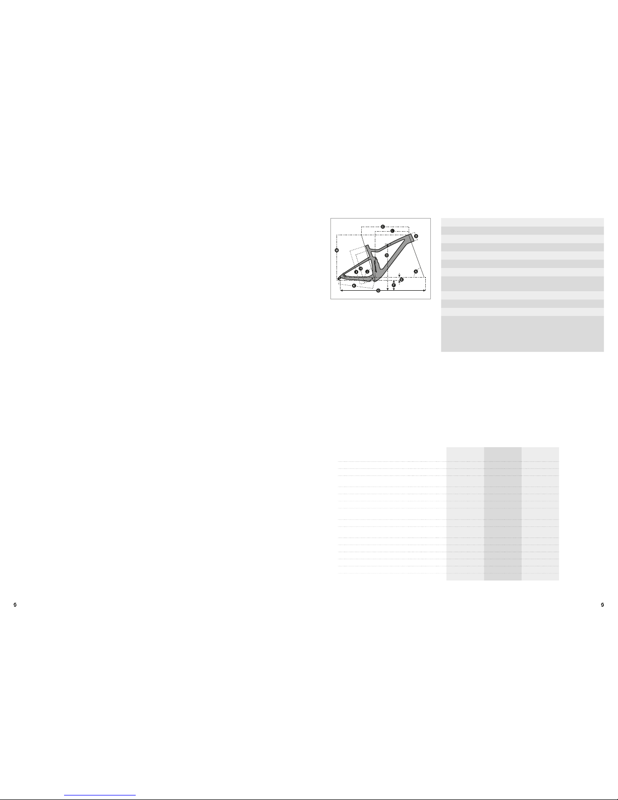
GEOMETRY/TECHNICAL DATA SPARK RC 27.5"
•
SPARK CONCEPT
The Spark has the most succe ssful pedigree of any cross- country full suspension bike
ever made. At les s than 1749 grams with rear shock, the top of th e line model is one of
the lightest full suspensio n frames available on the market. The new platform was not only
designed to provide a lighter and stiffer frame, but also to optimize kinematics. The bike
includes a h ost of minute, exquisitely detailed smart techn ical solutions which combine to
make it one of the best overall full suspension cross country packages of all time.
The SCOT T Spark RC 700 series was enginee red with incredibly light materials. With
a combined we ight of 1749 grams, its f rame inclu ding shock is o ne of the lightest f ull
suspensio n rig to date. Meetin g our requirements for stif fness values and applying the
Boost standard to our race bike family, our engineers designed the Spark RC series with a
dedicated , no-co mpromise race target group in mind. The benchmark weight was not only
achieved by utilizing the lightest car bon fibers, but also thanks to our intelligent carbo n layup process.
Our historic expertise of carbon engineering is just one element that allows us to create such
light frame s. Utilizing a mix of new high-end carbo n fibers is another. Our HMX-SL Spark
frame utilizes th e strongest and lightest filaments to date. O ur choice of the m ost advance d
carbon fibers is followed by intensive use of specific tools, like FE A (Finite Element Analysis)
software , to map out the carbon lay-up. With our proprietary EvoLap -Technology, we can
simulate different forces on a virtual frame model an d adjust fra me construction accordin gly;
this allows us to build h ighly technic al frames.
When we designed the all new S park, we had o ne goal in min d: create the ultimate fullsuspensio n Cross-Co untry bike. C omparing the old and the n ew Spark, we’ve moved from a
single pivot top link design to a single pivot rocker link layout with a Trunnio n shock mount.
Refined suspension characteristics were one of our m ain intentions . We created a system
that offers sensitive characteristics at th e beginnin g of the travel, the perfect support from
sag point onwards plus an optimized end progression. The new Spark furthermore has a
higher main pivot position to offer the most ef ficient pe daling characteristics .
The new platform enable d us to realize everything you could want f rom modern fullsuspensio n geometr y- a slacker head angle for maximum stability, shorter chain stays for
agile handling and lower stand over height /center of gravity for a more planted feel . We
designed it with a low stack for an o ptimized race fit and with a long reach with shorter
stem options for the same fit and better han dling. A stee per seat tube offers more balanced
weight distrib ution and bet ter power transfer. With a large numbe r of riders and a wide
range of uses in mind, we develo ped no- compromise s, high per formance g eometry- a
modern interpretation of what progressive race rs and riders need.
Trav el 100mm/70mm/Climb
Suspension ratio 2.50
Shock length 165mm
Shock stroke 40mm
Hardware mainframe Tr un ni on
Hardware linkage 20x10 mm
Seatpost diameter 31.6
Headset bearing s: 51.9x40x8 45 ° x 45 °/
41.8x3 0.5x8 45 ° x 45 °
Fork travel 110mm
Fork length 48 7.7 mm
BB Housing BB PF92
Max tire widt h 2.35/60mm
Please note:
Tire size s often vary from b rand to brand.
Ensur e the tire cleara nce is adequate
when replacing your tires!
05 |
BIKE USE R MANUAL | SPARK MY 2017SPARK MY2017 | BIKE USER MANUAL
| 04
Page 4

S M L XL
A HEAD TUBE ANGLE 68.5 ° 68.5 ° 68.5 ° 68.5 °
B HEA D TUBE LENGTH 95.0 mm 3.7 in 95.0 mm 3.7 in 105.0 mm 4.1 in 115.0 mm 4.5 in
C TOP TUBE HORIZONTAL 570.0 mm 22.4 in
600.0
mm
23.6 in 630.0 mm 24 .8 in 650.0 mm 25.6 i n
D STANDOVER HEIGHT
E BB O FFSET -50.5 mm -2 .0 in -50.5 mm -2. 0 in -50.5 mm -2.0 in -50.5 mm -2.0 in
F BB HEIGHT 319.5 m m 12. 6 in 31 9.5 mm 12.6 in 319.5 mm 12.6 in 319.5 mm 12.6 in
G WHEEL BASE
1,0 97.7
mm
43.2 in 1, 127.7 mm 44 .4 in
1,158.6
mm
45.6 in 1,1 79.6 mm 46.4 in
H BB CENT ER TO TOPTUBE CENT ER
I BB CENTER TO TOP O F SEATTUBE 410.0 mm 1 6.1 in
440.0
mm
17.3 in 490.0 mm 1 9.3 in 540.0 mm 21 .3 in
J SE AT ANG LE 73.8 ° 73.8 ° 73.8 ° 73.8 °
K CH AIN STAY 435.0 mm 17.1 in 435 .0 mm 17.1 in 43 5.0 mm 17.1 i n 435.0 mm 17.1 i n
L R EACH 399.5 mm 15.7 in 429. 5 mm 16.9 in 456 .8 mm 1 8.0 in 474.1 m m 18.7 in
M STACK 58 6.9 mm 23. 1 in 586.9 mm 23.1 in 596. 2 mm 23. 5 in 605 .5 mm 23. 8 in
N STEM LENGTH 60.0 mm 2.4 in 70.0 mm 2.8 in 80.0 mm 3 .1 in 90.0 mm 3.5 in
0 TRAIL 90.9 mm 3.6 i n 90.9 mm 3. 6 in 90.9 mm 3 .6 in 90.9 mm 3.6 in
S M L
A HEAD TUBE ANGLE 67. 0 ° 67.0 ° 67. 0 °
B HEA D TUBE LENGTH 100.0 mm 3 .9 in 105.0 mm 4.1 in 115.0 mm 4 .5 in
C TOP TUBE HORIZONTAL 575.0 m m 22.6 i n 605.0 mm 2 3.8 in 63 5.0 mm 25. 0 in
D STANDOVER HEIGHT
E BB O FFSET -26.0 m m -1 .0 in -2 6.0 mm -1.0 in -26.0 mm -1.0 in
F BB HEIGHT 32 5.5 mm 12. 8 in 325. 5 mm 12.8 in 325.5 mm 1 2.8 in
G WHEEL BASE 1,115.2 mm 43.9 in
1,145.8
mm
45.1 in 1, 177. 0 mm 46 .3 in
H BB CENT ER TO TOPTUBE CENT ER 345.0 mm 13 .6 in 375.0 mm 1 4.8 in 425.0 mm 1 6.7 in
I BB CENTER TO TOP O F SEATTUBE 410.0 mm 1 6.1 in
440.0
mm
17.3 in 490.0 mm 1 9.3 in
J SE AT ANG LE 73.8 ° 73.8 ° 73.8 °
K CH AIN STAY 428.0 mm 16. 9 in 42 8.0 mm 16.9 in 428. 0 mm 1 6.9 in
L R EACH 409.7 mm 16.1 in 438.4 mm 1 7.3 in 465.7 mm 1 8.3 in
M STACK 568.9 mm 22.4 in 573. 5 mm 22 .6 in 582.7 mm 22.9 i n
N STEM LENGTH 50.0 mm 2.0 in 60.0 mm 2.4 in 70.0 mm 2 .8 in
0 TRAIL 101.4 mm 4.0 in 101.4 m m 4.0 in 101 .4 mm 4.0 in
ENGLISHENGLISH
•
GEOMETRY/TECHNICAL DATA SPARK RC 29"
•
GEOMETRY/TECHNICAL DATA SPARK 27.5"
Trav el 100mm/70mm/Climb
Suspension ratio 2.50
Shock length 165mm
Shock stroke 40mm
Hardware mainframe Tr un ni on
Hardware linkage 20x10 mm
Seatpost diameter 31.6
Headset bearing s: 51.9x40x8 45 ° x 45 °/
41.8x3 0.5x8 45 ° x 45 °
Fork travel 110mm
Fork length 500.8mm
BB Housing BB PF92
Max tire widt h 2.35/60mm
Please note:
Tire size s often vary from b rand to brand.
Ensur e the tire cleara nce is adequate
when replacing your tires!
Trav el 120mm/85mm/Climb
Suspension ratio 2.67
Shock length 165mm
Shock stroke 45mm
Hardware mainframe Tr un ni on
Hardware linkage 20x10 mm
Seatpost diameter 31.6
Headset bearing s: 51.9x40x8 45 ° x 45 °/
41.8x3 0.5x8 45 ° x 45 °
Fork travel 120mm
Fork length 50 7.7m m
BB Housing BB PF92
Max tire widt h 2.35/60mm
Please note:
Tire size s often vary from b rand to brand.
Ensur e the tire cleara nce is adequate
when replacing your tires!
07 |
BIKE USE R MANUAL | SPARK MY 2017SPARK MY2017 | BIKE USER MANUAL
| 06
Page 5

S M L XL
A HEAD TUBE ANGLE 67. 2 ° 67. 2 ° 67. 2 ° 67. 2 °
B HEA D TUBE LENGTH 95.0 mm 3.7 in 95.0 mm 3.7 in 105.0 mm 4.1 in 115.0 mm 4.5 in
C TOP TUBE HORIZONTAL 575.0 m m 22.6 i n 605.0 mm 2 3.8 in 63 5.0 mm 25. 0 in 655.0 m m 25.8 in
D STANDOVER HEIGHT
E BB O FFSET -43 .0 mm -1.7 in -43.0 mm -1.7 in -43.0 mm -1.7 in -43 .0 mm -1.7 in
F BB HEIGHT 327.0 mm 1 2.9 in 3 27.0 m m 12. 9 in 32 7.0 mm 12.9 in 327.0 mm 1 2.9 in
G WHEEL BASE 1,121. 6 mm 44. 2 in 1,151.6 mm 45.3 i n
1,182.8
mm
46.6 in
1,203.9
mm
47.4 in
H BB CENT ER TO TOPTUBE CENT ER 345.0 mm 13 .6 in 375.0 mm 1 4.8 in 425.0 mm 1 6.7 in 475.0 m m 18.7 in
I BB CENTER TO TOP O F SEATTUBE 410.0 mm 1 6.1 in
440.0
mm
17.3 in 490.0 mm 1 9.3 in 540.0 mm 21 .3 in
J SE AT ANG LE 73.8 ° 73.8 ° 73.8 ° 73.8 °
K CH AIN STAY 438.0 mm 17. 2 in 4 38.0 mm 1 7.2 in 438.0 mm 1 7.2 i n 438.0 m m 17.2 in
L R EACH 402.7 mm 15 .9 in 432.7 m m 17.0 in 460.0 mm 18.1 in 47 7.3 m m 18 .8 in
M STACK 593.1 mm 2 3.4 in 593. 1 mm 23.4 in 602.4 mm 23.7 in 611.6 mm 24 .1 in
N STEM LENGTH 50.0 mm 2.0 in 60.0 mm 2.4 in 70.0 mm 2 .8 in 80.0 mm 3.1 in
0 TRAIL 100. 2 mm 3. 9 in 1 00.2 mm 3 .9 in 100.2 mm 3 .9 in 100.2 mm 3 .9 in
S M L XL
A HEAD TUBE ANGLE 66.9 ° 66.9 ° 66. 9 ° 66. 9 °
B HEA D TUBE LENGTH 95.0 mm 3.7 in 95.0 mm 3.7 in 105.0 mm 4.1 in 115.0 mm 4.5 in
C TOP TUBE HORIZONTAL 576.9 m m 22 .7 in 6 07.0 m m 23 .9 in 6 37.0 mm 25 .1 in 65 7.0 m m 25 .9 in
D STANDOVER HEIGHT
E BB O FFSET -36.0 mm -1.4 in -36.0 mm -1.4 in -36.0 m m -1 .4 in -3 6.0 mm -1.4 in
F BB HEIGHT 329. 0 mm 1 3.0 in 329.0 mm 13 .0 in 3 29.0 mm 13.0 in 329 .0 mm 13.0 in
G WHEEL BASE 1,128.1 mm 44. 4 in 1,158.1 mm 45.6 in
1,189.3
mm
46.8 in
1,210.5
mm
47.7 i n
H BB CENT ER TO TOPTUBE CENT ER 345.0 mm 13 .6 in 375.0 mm 1 4.8 in 425.0 mm 1 6.7 in 475.0 m m 18.7 in
I BB CENTER TO TOP O F SEATTUBE 410.0 mm 1 6.1 in
440.0
mm
17.3 in 490.0 mm 1 9.3 in 540.0 mm 21 .3 in
J SE AT ANG LE 73.2 ° 73.2 ° 73.2 ° 73. 2 °
K CH AIN STAY 438.0 mm 1 7.2 i n 438. 0 mm 17.2 in 43 8.0 mm 17. 2 in 438.0 mm 1 7.2 in
L R EACH 396. 3 mm 15.6 in 426 .4 mm 16.8 in 453 .6 mm 17. 9 in 470.9 mm 18.5 in
M STACK 5 98.1 mm 23 .5 in 598.1 m m 23.5 in 60 7.3 mm 23 .9 in 616. 5 mm 24.3 in
N STEM LENGTH 50.0 mm 2.0 in 50.0 mm 2.0 in 60.0 mm 2 .4 in 70.0 mm 2.8 in
0 TRAIL 100.2 mm 3.9 in 100.2 mm 3.9 in 100.2 mm 3.9 in 100.2 mm 3.9 in
ENGLISHENGLISH
•
GEOMETRY/TECHNICAL DATA SPARK 29"
•
GEOMETRY/TECHNICAL DATA SPARK PLUS
Trav el 120mm/85mm/Climb
Suspension ratio 2.67
Shock length 165mm
Shock stroke 45mm
Hardware mainframe Tr un ni on
Hardware linkage 20x10 mm
Seatpost diameter 31.6
Headset bearing s: 51.9x40x8 45 ° x 45 °/
41.8x3 0.5x8 45 ° x 45 °
Fork travel 120mm
Fork length 572.1mm
BB Housing BB PF92
Max tire widt h 2.35/60mm
Please note:
Tire size s often vary from b rand to brand.
Ensur e the tire cleara nce is adequate
when replacing your tires!
Trav el 120mm/85mm/Climb
Suspension ratio 2.67
Shock length 165mm
Shock stroke 45mm
Hardware mainframe Tr un ni on
Hardware linkage 20x10 mm
Seatpost diameter 31.6
Headset bearing s: 51.9x40x8 45 ° x 45 °/
41.8x3 0.5x8 45 ° x 45 °
Fork travel 130mm
Fork length 53 7.1 mm
BB Housing BB PF92
Max tire widt h 2.35/60mm
Please note:
Tire size s often vary from b rand to brand.
Ensur e the tire cleara nce is adequate
when replacing your tires!
09 |
BIKE USE R MANUAL | SPARK MY 2017SPARK MY2017 | BIKE USER MANUAL
| 08
Page 6

ENGLISHENGLISH
•
IMPORTANT!
SCOTT Spark is designed around the BOOST pl atform so ma ny of the fitted parts: cranks/
wheels/dropo uts/forks d iffer fro m traditional cycle par ts. Always consult your aut horized
SCOTT dealer for advice on replacing or repairing any part of your SCOTT bike!
•
TWINLOC
The TWINLOC system offe rs simultaneous control of the front and rear shocks with a single
lever allowing the ride of the bike to be adjusted at the flick of a fi ng er.
The 3 basic fu nctions of T WINLOC syste m are:
- Climb-out Mode: Climb rear / climb front
- Traction Mode: Traction mode rear / platform mode front
- Descent Mode: Full travel rear / fu ll travel front
You can only assemble the “standard” TWI NLOC remote lever in “left side upward position”
on the handl ebar (this is usually fitted on bikes with x2 front chainrings.)
On bikes with x1 chainring on the front the under ba r TWINLOC remote lever in “left side
downward” positio n can be fitted as standard.
It is possible to ch ange the TWINLOC lever to the un derbar option if the bikes gears have
been chan ged to x1 system, a new alternative lever will be re quired for this a djustment ;
please consult your local S COT T dealer for more information on obtaining the correct lever
for you bike.
There are 3 positions of the TWI NLOC remote l ever.
1. CLIMB MODE:
The shock is nearly locked; climbing on asphalt roads is now possible with lit tle power loss.
A simultane ous blow-of f-system prevents the shock being damage d in case the rider does
not open the system while crossin g obstacles.
2. TRAC TION MODE:
By reducing th e internal cha mber volume inside the shock the travel of the sho ck will
be reduced , the charac teristic of the air spring gets h arder this results in climbing with
reduced “bobbing” an d offers still optimum traction of the rear wheel.
3. DESCENT MODE:
Full travel of the front and rear shocks.
You will find the following positions on the remote lever:
•
BASIC SET-UP OF SHOCK & FORKS
Recommended tools for th e shock setup:
- The SAG tool that came with your bike.
- A shock pum p with a dial up to 20bars/300psi with a specia l air valve conne ctor (not
supplied with this bike), this will help stop air f rom escaping while removing the pump
from the shock valve.
Please note that air will flow into the hose and indicator when counterch ecking the air
pressure, this will give the appearance that the shock has less air pressure then it was setup,
your shock may need to be adjusted once this action is made.
Please also n ote that the indicators of shock pumps have a tolerance of max. 10% .
For bikes spec ’d with Fox shock and forks:
You can find more specific inform ation about Fox set u p on Fox’s website, please use your
fork/shock I D number to find more useful setup tips for your exac t fork and sho ck (please
visit: ridefox.com)
11 |
BIKE USE R MANUAL | SPARK MY 2017SPARK MY2017 | BIKE USER MANUAL
| 10
Page 7

* Fox Nude model shown
ENGLISHENGLISH
•
SAG
You r SCOTT bike will be supplied with a SAG tool to help set up your bikes suspension, these
SAG tools can be easily clipped on the shock body and fork dus t seal.
For the best performance it is recommended you sta rt with SAG of 25-30% for shock s and
15-2 0% fo r forks.
1. Make sure before any adjustment is made that your shock and forks are in the “open”
position.
2. With the shock pu mp attache d to the rear shock valve, pump your d esired pressu re
into the shock. Once the pressure is achieved slowly compress and d ecompress your
shock throug h 25% of its travel 10 times. This will equalize the positive and negative air
chambers and will change the pressure on the pump gauge, if need ed add or reduce
pressure and repeat.
Note the compression/decompression of the rear shock through the travel must also
be done if th e pressure i s reduced!
3. Once your desired pressure is reached slide the rubber O -ring on the shock and for k leg
against the dust seal, clip on your SAG tool if required.
4. Sit on your bike in your usual riding position (in your riding ge ar: if you carry a bag/
Hydration-system put it on,) d on’t “boun ce” the suspension while doing this, use a wall or
a friend for support if needed.
5. Get off the bike gently without b ouncing an d check the O -ring position on the shaf t or
the fork stan chion, with th e SAG adjuster clipped on. This makes it easy to see where your
SAG is set. Example bel ow.
The same op eration is use d on the forks.
•
IMPORTANT!
Do not sit on your bike with the shock pump at tached to the bike!
•
REBOUND SHOCK SET-UP
“Rebou nd” describes the speed the shock retu rns back to its original length after absor bing
an obstacle, setting of this is very important for the h andling an d correct function of the bike.
The reboun d adjustment lever can be fou nd on the head of the shock
After the shock pressure/sag is co rrectly set ride your bike in a safe area with your riding
gear/backpack, etc. While re maining in the saddle, ride you bike off a drop/kerb of about
10-15 cm .
- If it bounce s 1-2 times and settles the set-u p is good.
- If it bounce s more than 3 time s the rebound is too fast, turn the knob 1-2 “clicks”
clockwise and repeat.
- If there is no bounce the rebound is too slow, turn the knob 1-2 click counter clockwise
and repeat.
- Repeat these steps until the d esired result is achieved .
You r SCOTT SPARK bike was desig ned to be used in conjunction with a specific sh ock and
forks, cha nging the shock or forks on your bike may cause poor/unsafe riding characteristic s
or damage to frame and components , please consult your SCOTT dealer for any assistance
you need, f ailure to do this may af fect your warranty
13 |
BIKE USE R MANUAL | SPARK MY 2017SPARK MY2017 | BIKE USER MANUAL
| 12
Page 8

ENGLISHENGLISH
If your dropout needs to be replaced, we recom mend this work should be ca rried out by
your local S COTT dealer as the rear dera illeur may need adjustment, failure to ad just this
correctly may result in accident o r damage to your b ike.
•
IMPORTANT!
We recommend all work should be carried out by your authorised SCOTT dealer!
If you wish to change this item yourself, please ensure the b ike is suppor ted correctly to
prevent damage by referring to the general manual instructions supplied with your bike .
•
REPLACEABLE REAR DROPOUT
On SCOT T SPARK mod els for 2017 the re ar deraille ur hanger is replaceable, depending on
your model of S COT T SPARK there are 5 different hangers availa ble, 2 for carbon swingarms
and 3 alloy swing arms, these parts can be seen be low, please consult your SCOT T dealer for
information on the correct part.
FOR CARBON SWINGARMS ONLY:
Sram and non-direct
mount derailleurs
SCOT T part
number 254090
Sram and non-direct
mount derailleurs
SCOT T part
number 2540 92
Non-Direct mount
derailleurs and boost
Q/R wheels
SCOT T part
number 254094
Shimano direct mount
derailleurs
SCOT T part
number 2540 91
Shimano direct mount
derailleurs
SCOT T part
number 251093
FOR ALLOY SWINGARMS ONLY:
Before installing the new hanger first
make sure the area is clean; insert
the hanger.
Insert th e end cap through the fram e and
into the hanger.
Make sure the location arrow is pointing
to the lower bolt hol e; insert th e bolt (Max
torque 1.5 N/M)
Insert th e second bolt in the rear of the
dropout (Ma x torque 1.5 N/M)
(Carbon swingarm fitting sh own)
Once the bike is reassemble d please insure the wheels are refitted correc tly and the gears
are set correctly including th e over shift stops , please consult your authorized SCOT T dealer
for assistance.
•
PIVOT MAINTENANCE
The pivot and be arings on the S COT T SPARK are easy to maintain.
If you have to change the bearings or pivots please consult your local SCOT T deal er for the
purchase and fitting of the kit as special tools are required for disassembly and reass em bly.
To prolong the life of your pivot be arings an external treatment with water repelle nt after
every bike wash will help repel excess water. We do not recommend heavy grease sprays
since these will leave a film on the pa rts which are difficult to remove. We recommend the
same for the chain also after washing and b efore chain lub e; Do not let sp ray or oils come
into contac t with the disc brake pads or rotor!
Please refer to the manuals supplied with this bike for wash and care instructions for your
SCOT T bike.
15 |
BIKE USE R MANUAL | SPARK MY 2017SPARK MY2017 | BIKE USER MANUAL
| 14
Page 9

ENGLISHENGLISH
•
CABLE GUIDES AND CABLING.
On the carb on SCOT T SPARK the cable guid es on the headtube can be changed if required
so different cable configurations c an be used, the inside of the c able guide is stamped with a
number or n umbers , these numb ers dictate what c ables can be used, these are the same for
left and right.
The numbe rs indicate what cables fit the guide; the g uide shown will ho ld 2 mechanical
cables an d one hydraulic.
They are available in the following combinations and are available f rom your SCOTT d eale r.
4 = mechanical cable
5 = hydraulic cables
DI2 = DI2
Blank= no cable
Combinations:
4, 4-5-5,
5, 4-4-5,
4-4, DI2,
4-5, 4-DI2,
5-5, 5- DI2,
4-5-DI2
Please be aware , to prevent damage to the frame and c ables there should be minimum cable
clearance between the b ottom of the bottom bracket and th e cables.
The measure ment should be a minimum of 25mm taken in the centre line of the bottom
bracket, as in dicated in the image.
These cable guides are f itted with a single bolt, the fixing torque of this must not exceed
0.75-1 N/M.
With the many dif ferent cabling options it is possible to customise the cable routing slightly
depending what compo nents you wish to ru n, it is recommended that h andlebar cables
that come from th e right hand side enter the fra me on the lef t, and handlebar cables that
come from the left hand side enter the fra me on the right, while this is not crucial to the
perform ance of the bike it may help to prevent any cable rub
Below is an example of a bike set up “European style” with a 1X set up and a dropper seatpost.
Please note t hat below is an example and that your bikes brakes need to be set up as per
the law in your co untry, please check with your local SCOTT deale r for this information.
•
BB STANDARDS/FD MOUNTING DETAILS
The SCOT T SPARK has a Press fit PF92 bot tom bracket with an inner diameter of 41mm, this
is a press fit system and special tools are required for removal and ref itting, please contact
your SCOT T dealer for assistance.
The SCOT T SPARK (non RC models) uses a high direct mount side swin g front derailleur
only, this must be used with the use of an FD adaptor plate.
It is not poss ible to mount a front
derailleur to RC frames/bikes.
•
ADJUSTMENT
We recommend all adjustments are carried out by your local authorized S COTT dealer but
basic maintenance and che cks should b e done regularly before each ride as described in the
general m anual that was supplied with you r bike.
Please pay attention to all instructions and torque settings , if you have any doubts please
contact your deal er,
*in addition to the torque set tings please note a ll bikes wit h a dropper type seat post
have a seatpo st clamp maximum torque of 5 N/M .
17 |
BIKE USE R MANUAL | SPARK MY 2017SPARK MY2017 | BIKE USER MANUAL
| 16
Page 10

SCOTT Bikes
Gambler, Voltage FR, Volt-X
5
ENGLISHENGLISH
•
GUARANTEE ON SCOTT BIKES
•
WARNING!
SCOTT Spo rts SA is not r esponsible or lia ble for any i njury caused by any missing
complia nce with th ese inst ructions, particularly but not lim ited to mis use, inco rrect
maintenance, incorrect set-up and handlin g, neglect or abuse. Failure to follow these
instructions can result in component failure, serious personal injury. Component failure
can lead to loss of control of the bi cycle and result in serious pers onal injury.
What is Cover ed?
This warrant y covers defect s in materials an d workmanship at the time of transfer of risks in
frames, swingarms and forks (provided it is a fork of SC OTT ) on SCOTT bra nded bikes sold
completely as sembled by S COTT or an authorized SCOT T deal er (“Produ ct”).
How long do es coverage las t?
This voluntar y manufacturer’s warranty is limited to five years for fram es and swinga rms,
respectively two years for fork s, from the date of p urchase of the Product and is lim ited
to the first purchaser of the Prod uct and subject to the prior re gistration of you r SCOT T
bike on www.scott-sports .com within 10 days as of the date of purchase. Transfer of
the Product f rom the first p urchaser to another person terminates this lim ited warranty.
The limited warranty of five year s for the frames and swingarms shall only be granted
in case once a year a maintenance service has been effected according to maintenance
requireme nts as set forth in the manual. The effe cted annual maintenance service shall
be confirmed by stamp and signature. In case such an annual maintena nce service has
not been ef fected the warranty of five yea rs for the frame shall be reduced to three years.
Costs for maintenance and service have to be borne by the owner of th e Produc t.
On Gambler, Voltage FR and Volt-X the warranty period is limited to two years.
Repaired or re placed Prod ucts are covered fo r the remaind er of the original warranty
period and subject to the co nditions outlined in the original warranty, to the extent
permi tted by law.
Hereby SCOTT grants a worldwide voluntarily man ufacturer ’s warranty. To the extent
permitted by law and unless a sh orter duration is stipulated by law, any warranties implied
by law are limited in duration to maximum five, respectively two years, from the date of
purchase of the P roduct and a re limited to the first purchaser of th e Product.
What will SCOTT do?
SCOT T will replace or repair any defective Product, or will refun d your purchase p rice (as
evidenced by your tendered receipt of purchase of th e Product), at SC OTT ’s option. You
must pay charges in connec tion with replacement of any non -defec tive parts . In such a
case, you will b e alerted to the a dvisabilit y of replacing n on-defective part s, so you can
pre-authorize the costs .
What does t his limi ted warran ty not cover?
This limited warranty does n ot cover defects which did not exist b efore the transfer of
risks. This limited warrant y does not cover Pro ducts use d in rental operations. This limited
warranty does not cover purchases of not completely assembled bikes. This limited warranty
does not cover any defect caused by “wear and tear” (a complete list of all pa rts of “wear
and tear” c an be found in th e general manual that c ame with your bike), accident, neglec t,
improper handling, co lour fade d ue to exposure to sunlight, abuse, misuse, an act of God,
improper assembly, non-compliance with recommended maintenance and care procedures,
improper or incorrectly p erformed maintenance or repairs performe d by someone oth er
than an autho rized SCOT T dealer, use of parts or devices not consistent with the Product,
and alteration of the Product.
All Product s come with a manual; please c arefully follow the instructions located th ere
or affixed e lsewhere to the Prod uct. To the extent permitted by law, consequential and
incidenta l damages are not recoverable under this limited warranty.
How do you make a claim under this lim ited warranty?
To make a claim under this li mited warrant y, you must notify S COTT of the claime d defect
within the warra nty period and timely return the Product to SCOT T at your expense for
inspection. Please contact your authorized SCOTT dealer, call S COTT ’s customer service
or the national SCOT T distributor (dealer locator: www.scott-sports.com). All returned
Products m ust be accompanied by proof of p urchase (receipt) from an authorized SC OTT
dealer or this limited warranty will not apply. In case of replacement or refu nd, returne d
Product becomes the property of SCOTT.
A protocol for the handing over of the Product (which you will find at the end of the manual)
will remain in copy at the SCOT T deal er after acce ptance and signature of the consumer. It
is obligator y to show this protocol of han ding over togethe r with the defective part in case
of a warranty cl aim given that it provid es evidence of purchase or this limited warranty will
not app ly.
How do state laws affec t your right s under this limited warranty?
This limited warranty gives you sp ecific legal rights, and you may also have other rights,
which vary f rom state to state .
Recommendation
We strongly recomm end that you use only authorized S COTT dealers for yearly maintenance
services and for repairs, as improper or incorrectly performed maintenance or repairs voids
this limited warranty. Costs for m aintenance se rvice have to be bor ne by the con su mer.
19 |
BIKE USE R MANUAL | SPARK MY 2017SPARK MY2017 | BIKE USER MANUAL
| 18
 Loading...