

Page 1

SCOTT 2011
BIKE OWNERS
MANUAL
SCOTT SPORTS SA | 17 RTE DU CROCHET | 1762 GIVISIEZ | SWITZERLAND
© 2009 SCOTT SPORTS SA, ALL RIGHTS RESERVED | SCOTT-SPORTS.COM
C
SPARK
Page 2
CONTENT
Spark Concept P. 004
Geometry Spark P. 005
Technical data Spark P. 006
The Spark should be adjusted exactly to the current rider
for reaching maximum safety and fun while riding.
SPARK
All adjustments should be done at the local Scott dealer or
following to this manual.
TWINLOC remote control P. 007
Assembly of the remote cable P. 011
Nude TC Shock and TWINLOC remote control P. 014
Basic Set-Up of the TWINLOC remote control of Nude TC shock P. 015
Recommended Tools for the Shock Set-Up P. 018
Set-Up Spark with Nude TC Shock P. 019
Set-up of Rebound Nude TC Shock P. 021
Set-up of other Shock Models P. 023
Scott Smart Cable Routing P. 023
Adjustment of Seatpost-Height P. 024
Replaceable Drop Out P. 024
Front Fork Set-Up/ Change of Front Fork P. 025
Pivot Maintenance P. 025
Warranty P. 026
SPARK
ENGLISH
2 2011 SCOTT BIKE OWNERS MANUAL
3
Page 3

SPARK CONCEPT
Spark is the result of 2 years of research and development for the lightest mountain
bike frame set available on the market, hitting the scale at below 1800 grams (4
pounds) including the frame, Scott Nude TC shock and TWINLOC remote control.
Scott’s focus was not only on lightweight but also on a durable frame with an
innovative suspension technology in combination with an optimized kinematics of the
rear swingarm.
The combination of an optimized kinematics with an extraordinary suspension
technology closes the gap between superlight hardtail bikes (e.g. Scott Scale) and the
new generation of marathon bikes (e.g. Scott Genius).
SPARK
Spark was designed for riders looking for a dual suspended race and marathon bike
offering a maximum rear wheel travel of 110mm.
Scott does not see frame, rear shock and kinematics as single components which are
assembled together on a bike, but as a concept with all these components working
together and offering an outrageous function by matching perfectly.
GEOMETRY SPARK
Size
A
Head
angle
length
°
C IHGEB D
Effective
top tube
horizontal
Seat angleHead tube
BB center
to top of
seattube
F
BB center
to top tube
center
mm inches
Chainstay
length
BB
offset
Standover
height
Stem
length
mm°mm mm inches mm inches mm inches mm inchesmm inches
Crankarm
length
mm
SPARK
Kinematics
The Spark Concept is based on a new designed multi-pivot technology.
In combination with the linear shock characteristics the chain tension will be reduced
and doing so the pedaling will not influence function or movement of the rear
swingarm.
The Scott system, named TC (Traction Control) will allow you to reduce by remote
control the rear wheel travel from 110mm to 70mm including a more progressive spring
rate but still offering a supple break away.
No power will be lost and an optimum power transfer is guaranteed as the swingarm,
in contrary to locked or automatic-locking systems, can follow the trail surface and will
offer perfect traction and higher speed while standing on the pedals.
SPARK CARBON
69.5°
S
69.8°
M
70.0°
L
70.0°
XL
SPARK ALLOY
69.0°
S
69.0°
M
69.0°
L
69.0°
XL
28.6
29.8
32.5
28.6
29.8
32.5
90
170
90
175
100
31.1
31.1
175
110
175
90
170
90
175
100
175
110
175
ENGLISH
23.0
24.0
25.2
23.0
24.0
25.2
73.5°
400
450
490
540
400
450
490
540
15.7
17.7
19.3
21.3
15.7
17.7
19.3
21.3
21.9
73.5°
73.5°
73.5°
73.5°
21.9
73.5°
73.5°
73.5°
422
16.6
-10
-0.4
337
13.3
422
387
429
479
337
387
429
479
16.6
15.2
422
16.6
16.9
422
16.6
18.9
422
16.6
13.3
422
16.6
15.2
422
16.6
16.9
422
16.6
18.9
727
-10
-0.4
758
-10
-0.4
789
-10
-0.4
825
-7
-0.3
727
-7
-0.3
758
-7
-0.3
789
-7
-0.3
825
110
43
555
120
4.7
585
140
5.5
610
160
6.3
640
110
43
555
120
4.7
585
140
5.5
610
160
6.3
640
4 2011 SCOTT BI KE OWNERS MANUAL
5
Page 4
TECHNISCHE DATEN SPARK TWINLOC – REMOTE CONTROL LEVER
4
3
Travel 110/70/0mm
Suspension Ratio 2.97
Piston stroke 37mm
Shock (Eye to Eye) 165mm
Hardware Mainframe 22,2mm x 6mm
Hardware Swingarm 22,2mm x 6mm
Seatpost diameter carbon frames 34,9mm; alloy frames 31.6mm
SPARK
Headset 1 1/8“semi integr. with 44.0mm cups
Fork travel 100 - 120mm
Fork length 471 - 491mm
BB housing 73mm
Front derailleur Downswing 34.9mm Downpull
Bearings 2 x 61900 (22x10xT6)
6 x 63800 (19x10xT7)
The TWINLOC remote control lever is the evolution of the already outstanding
TRACLOC system of Scott.
While TRACLOC allows the change on the Scott rear shocks Nude TC and Equalizer
2 between the Scott patented Lock-out, traction and full-mode on the fly from the
handlebar, the TWINLOC now allows also the remote control of the front fork to shift
between lock-out and open mode at the same time when you change the modes on
the Scott rear shox.
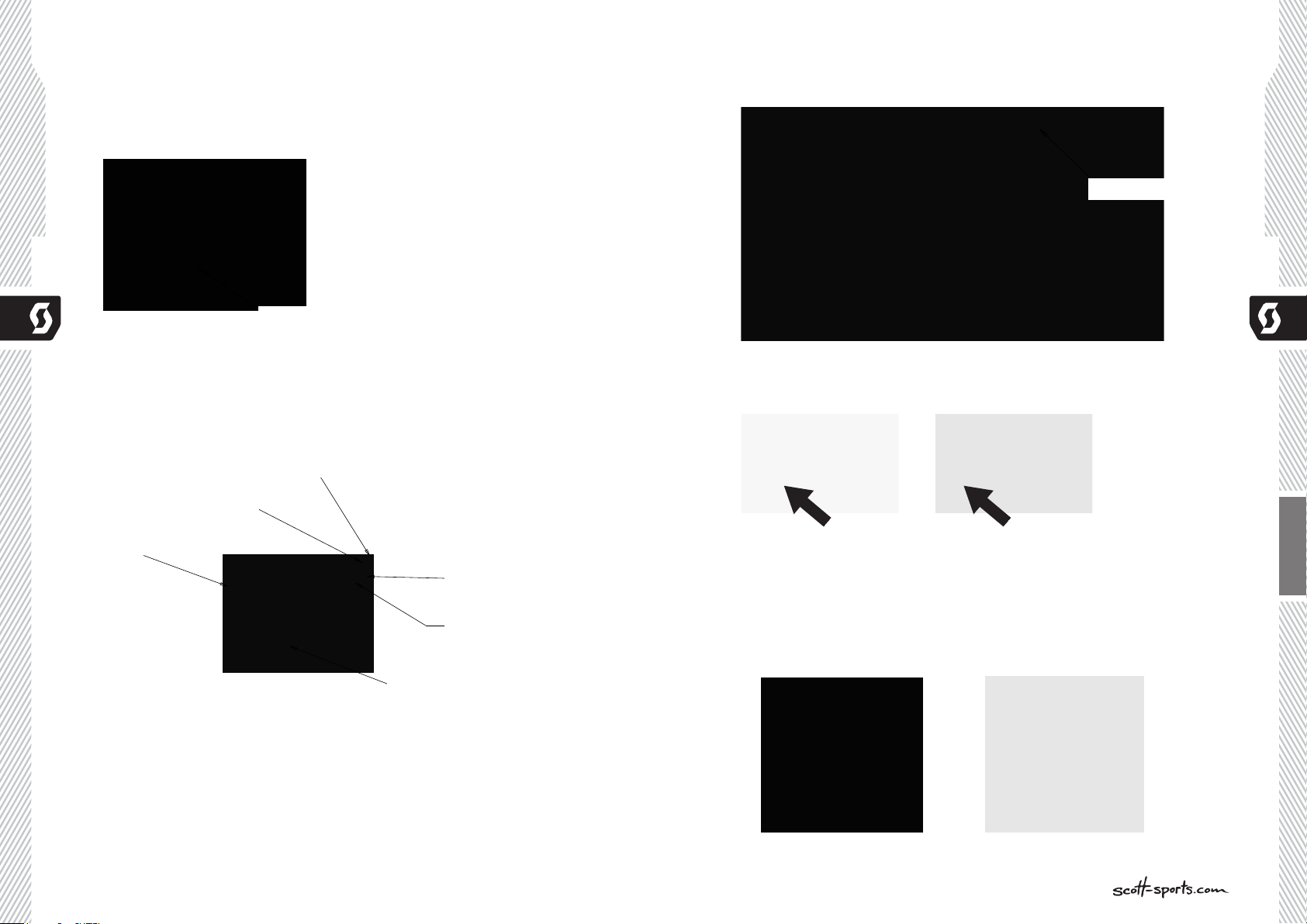
The 3 modes on the lever and suspension units are:
- FullTravelMode: full travel rear, full travel front
- TractionMode: traction mode rear, full travel front
- Lock-outMode: lock-out rear, lock-out front
Scott offers different TWINLOC levers with following fork/rear shock combinations:
- Nude TC with adapters for SRAM /RockShox fork and FOX fork/DT Swiss fork
(Scott Article number: 216351)
- DT M210 with adapters for SRAM /RockShox fork and FOX fork/DT Swiss fork
(Scott Article number: 216352)
Please note that the DT Swiss M210 rear shock does not offer a traction mode, but only
lock-out and full-mode.
Important: You can only assemble the TWINLOC remote lever in “left side upward
position” on the handlebar.
You have 3 positions on the TWINLOC remote lever.
- mostforwardposition: lock-out rear, lock-out front
- middleposition: traction mode rear, full travel front
- mostbackwardposition: full travel rear, full travel front
SPARK
ENGLISH
6 2011 SCOTT B IKE OWNERS MANUAL
Lock Out Mode
Traction Mode
Full Travel Mode
7
Page 5
3
2
4
3
2
LOCK OUT MODE
TRACTION MODE
ALL TRAVEL MODE
PRESS TO RELEASE
Change the modes by pushing the lever with your fingers frontward and release them
4
3
2
ROCK SHOX ROLL FORK
SEE DETAIL A
4
3
2
ROCK SHOX ROLL FORK
FOX - DT ROLL FORK
SEE DETAIL A
4
3
4
3
4
3
2
FORK REMOTE CONTROL CABLE
by tapping the release button (one mode per push/release)
Please note that the cable for the rear shock is ALWAYS the upper cable on the lever
as shown in drawing below.
FORK CABLE
rear shock cable
SPARK
Press to release
For the different parts of the TWINLOC lever mentioned in the following instruction
please refer to the drawing with parts names below:
Fork remote control cable
FORK CABLE TENSION SCREW
Fork cable tensien screw
REMOTE LEVER
Remote lever
SHOCK REMOTE CONTROL CABLE
Shock remote control cable
SHOCK CABLE TENSION SCREW
Shock cable tensien screw
RELEASE BUTTON
Release button
SPARK
There are different versions for different rear shock models.
Please make sure that your lever fits to the rear shock of the bike.
For the assembly of the remote control of the front fork lock-out 2 different cable
ENGLISH
systems are existing.
The different roll for the pull of the fork remote cable can be changed within few minutes
to adapt the lever to your fork model/brand.
You will see on the downside of the roll the indication of fork brand.
8 2011 SCOT T BIK E OWNERS MANUAL
9
Page 6

3
2
3
2
D C B A
3
To change the rolls to match another fork brand pls follow the drawings below:
4
3
ROCK SHOX ROLL FORK
SEE DETAIL A
4
3
2
ROCK SHOX ROLL FORK
SEE DETAIL A
3
2
ASSEMBLY OF THE REMOTE CABLE
Roll fork unmounting
SPARK
Torx T10
Fox-DT Roll fork
FOX-DT ROLL FORK
FIXATION HOLE
fixation hole
Rock Shox Roll fork
ROCK SHOX ROLL FORK
FIXATION HOLE
fixation hole
SRAM/RockShox forks:
Important:
Please make sure the lockout of SRAM/RockShox fork is activated after transport
correctly. Therefore please compress fork 5-10 times before following the manual on
remote cable installation and adjustment.
The lever should show on the downside of the able roll follow indication:
SPARK
See Detail A
To assemble the cable please bring the lever into the All Travel Mode, push the cable
into the lever-eyelet as shown on drawing below, push it through the pre-cut cable
housing and fix it at the assembly unit on top of the right side of the fork crown.
FORK CABLE
Fork cable
Detail A
ENGLISH
Roll fork mounting
Torx T10
10 2011 SCOTT BIKE OWNERS MANUAL
Fix the cable with the 2mm allen screw on the barrel adjuster on the fork crown with a
tightening torque of 0.9Nm/ 8lb/in, cut the cable and secure it with a cable end-cap.
Please refer for this action also to the manual of SRAM/RockShox attached to the bike.
2mm allen
11
Page 7

FOX-DT Swiss forks
4
3
ROCK SHOX ROLL FORK
FOX - DT ROLL FORK
4
3
2
ROCK SHOX ROLL FORK
FOX - DT ROLL FORK
SEE DETAIL A
Important:
Please make sure the lockout of FOX/DT fork is activated after transport correctly.
Therefore please compress fork 5-10 times before following the manual on remote
cable installation and adjustment.
The lever should show on the downside of the cable roll follow indication:
and secure the cable by fixing the 2mm allen screw with a tightening torque of
0.9Nm/ 8lb/in as shown on the drawing below on the roll.
SPARK
See Detail B
To assemble the cable please bring the lever into the Full (Travel) Mode
push the pre-cut cable through the pre-cut cable housing into the lever as shown on
drawing below
Full mode
Fork cable
Detail B
Contact (Roll/screw)
SPARK
!!! roll position !!!
Cut the cable 5mm behind the roll and secure it with a cable end-cap.
Please refer for this action also to the manual of FOX or DT Swiss attached to the bike.
In case you need to remove the remote cable completely from the forks of FOX
or DT Swiss please follow the instructions of the related fork manuals of the fork
manufacturers or contact a fork service center / your local dealer to do so.
TIP:
To check for accurate cable tension, please try to move the plastic end cap of the cable
housing at the barrel adjuster on the remote lever. There should be “no-play” between
cap and barrel adjuster.
ENGLISH
In case of “play” please turn the barrel adjuster clockwise until “no-play”.
12 2011 SCOTT BIKE OWN ERS MANUAL
13
Page 8

NUDE TC SHOCK UND TWINLOC
3
2
FORK CABLE
REMOTE CONTROL LEVER
BASIC SET-UP OF THE TWINLOC
REMOTE CONTROL OF NUDE TC SHOCK
In der untenstehenden Abbildung des Dämpfers und des Fernbedienungshebels können
Sie die Bauteile mit Nummern bezeichnet finden, die in dieser Bedienungs anleitung
verwendet werden.
S5S6S4
SPARK
S2
S9 S3 S8 S7
L1
L2
L3
L4
To ensure perfect function of the Nude TC shock it is very important to follow the steps
shown below exactly
IMPORTANT
For all following actions the TWINLOC lever needs to be in “ALL TRAVEL-MODE”
position!
SPARK
S1
thread in cable along the groove
1
and pull it tight gently
press the release lever twice whilst
2
still pulling the cable to set the
lockout-lever into the
«open» position
Thread in the cable...
3
ENGLISH
4
...make it stepping out along the
piggy back
S1 Front eyelet/ Shock Bolt L1 Remote Lever
S2 Rear eyelet/ Shock Bolt
S3 Piggy-Back
S4 Shock Housing
S5 Rebound-Screw
S6 Positive Chamber Valve
S7 Lock Out Barrel
S8 Cable fixing Screw
S9 Shock Piston
14 2011 SCOTT BIKE OWNERS MANUAL
L2 Release Lever
L3 Tension Screw
L4 Allen Screw
5
Unmount the M4 headless screw.
15
Page 9

Put on the end cap and make sure
9
to have at least 17mm of free cable
SPARK
17mm (min)
Create a loop and put it into the
6
open groove on the remote wheel..
length.
SPARK
view from below
In Traction Mode about parallel to
shock body
ENGLISH
Pull the cable tight...
7
...then tighten the headless 4mm-
8
screw by using a 2mm-Allen key
(max 1.3Nm)
hang in cable
16 2011 SCOTT BIKE OWNERS MANUAL
17
Page 10

BENÖTIGTE WERKZEUGE FÜR DAS
3
2
3
DÄMPFER SET-UP
SET-UP SPARK WITH NUDE TC SHOCK
For the set-up of the shock we recommend to use a shock pump with a scale up to 20
bars/300 psi with a special air valve connector preventing from air getting away while
removing the pump from the shock valve, this will result in an exact air pressure.
Pleasenotethatairwillflowintothehoseandindicatorwhencountercheckingthe
airpressure,soyouhavetosetupagaintherecommendedpressureafterthisaction.
Makesuretobalanceatleastthisairlosswhenyoumakeacheckoftheairpressure
oftheshock.Plsalsonotethattheindicatorsofshockpumpshaveatoleranceof
SPARK
max.10%
1
2
3
The Set-Up of the Scott Nude TC Shock can be easy done within a few minutes.
IMPORTANT
For all adjustments of the air spring the remote lever has to be in position “all travel”.
To adjust the air pressure of the positive chamber of the Scott Nude TC Shock please
refer to the following instruction:
1. Remove the valve cap of the valve (S6) located on the shock housing (S4).
2. Mount the shock pump with its adaptor on the valve
3. Pls take into account that it takes some air pressure from inside the shock to drive the
indicator on the pump. Make sure to balance at least this air loss when you make a
check of the air pressure of the shock. Pls also note that the indicators of shock
pumps have a tolerance of max. 10%
4. Pump the recommended pressure into the shock. On the inner side of the left
seatstays you will find a table showing the recommended air pressure of the positive
chamber according to the rider’s weight.
5. When you reached the needed pressure remove the pump and put the valve cap on
the valve
Recommended Air Pressure
SPARK
ENGLISH
18 2011 SCOTT BIKE OWN ERS MANUAL
19
Page 11

SAG
The SAG should be 5mm on the shock piston.
To check the adjustment, please follow as shown below:
1. Sit on the bike, put your feet on the pedal
2. Put your feet back on the ground and stand over the bike without bouncing the bike
during this action
3. Check if the o-ring on the shock piston has a distance of 5mm to the main dust
wiper/seal between shock housing and piston.
- if the distance between the o-ring and the main dust wiper/seal is less than 5mm,
the air pressure of the air chamber is too high and should be carefully reduced by
SPARK
using the bleed knob of the shock pump until the distance is 5mm.
- if the distance between the main dust wiper/seal is bigger than 5mm, the air
pressure of the air chamber is too low and should be increased by using the shock
pump until the distance is 5mm.
5mm
SET-UP OF REBOUND NUDE TC SHOCK
“Rebound” describes the speed the shock comes back to its original length after
absorbing an obstacle.
By using the red rebound screw (S6) you can adjust the rebound step by step.
Please refer to the following instruction:
Ride your bike off a pavement (remain in the saddle) and check how many times it
bounces.
- if it bounces 1-2 times, the set up is good.
- If it bounces more than 3 times the rebound is too fast.
Turn the screw 1-2 “clicks” clockwise
- If it does not bounce the rebound is too slow.
Turn the screw 1-2 “clicks” counter clockwise.
SPARK
IMPORTANT
Please note that the maximum pressure of the Nude TC shock is 15.4bar/223psi which
means a maximum weight of the rider of 110kg/243lbs incl. riding gear and load.
20 2011 SCOTT BIKE OWNERS MAN UAL
ENGLISH
21
Page 12

In case you want even more detailed figures of air pressure or tuning hints, you can
download a program under www.scott-sports.com as a MS Excel file.
SET-UP OF OTHER SHOCK MODELS
ScottstronglyrecommendsusingonlytheoriginallyassembledShockwiththe
Sparkbike,aswedesignedbothpartsforaperfectmatchingcombination.
For further set up instructions on those shocks please follow the manuals of the shock
producers attached to the bike.
If you want to use a different rear shock model than the one originally on the bike,
please make sure that the shock will not in any position hit the frame and cause
a damage to the frame.
SPARK
IMPORTANT:
Note that you have to mount the Scott Nude TC Shock always as shown underneath.
Mounting the rear shock in a different position can cause severe damages to the frame,
the linkage levers and the rear shock.
Please follow the instruction below:
Please make sure that the rear shock or its accessory parts do not touch the frame
when mounting or suspending.
For doing so release the air/remove the coil, install the shock and compress the shock
completely.
If the shock touches the frame while doing so, do not use this shock in order to avoid
damage to frame, swingarm or shock.
SCOTT SMART CABLE ROUTING
The direct and straight cable system on all our full suspension models allows Smart
Cable Routing which is very resistant against water and dirt.
To change the cables simply unscrew and open the cable brackets on the downtube.
SPARK
ENGLISH
IMPORTANT:
After a dismantlement of the rear shock, both fixing bolts should be tightened with a
tightening torque of 5Nm/44in-lbs.
If this is not done correctly the rear shock can be damaged.
22 2011 SCOTT BIKE OWNERS MANUAL
23
Page 13

MECHANICS HINT
The outer housing of the cables can also be fixed on the bottle cage with cable fixers,
the two brackets below the cage are not needed anymore..
ADJUSTMENT OF SEATPOST-HEIGHT
SPARK
FRONT FORK SET-UP /
CHANGE OF FRONT FORK
For the set up of the front fork please use the fork specific manual attached to the bike.
We recommend using front forks with a travel of 100 - 120mm, as this will not influence
the geometry and alter handling of the bike.
SPARK
IMPORTANT:
The seatpost has to be inserted into the seattube at a minimum of 100mm.
Never use another seatpost diameter than 34.9mm on carbon frames or 31.6mm on
alloy frames or try to use a shim/reducer between seatpost and frame.
REPLACEABLE DROPOUT
On Spark bikes you can replace the rear derailleur hanger.
In case the replaceable hanger is damaged by a crash or accident you can order at
your local Scott dealer the replacement part with Scott article number 206473
PIVOT MAINTENANCE
The pivot and bearings on SCOTT Spark are extremely easy to maintain.
An external treatment with a grease spray after every bike wash is all you have to do.
We do not recommend heavy grease sprays since these will leave a film on the parts
which is difficult to remove. We recommend the same for the chain also.
If you have to change the bearings you can order them included in a service kit at your
local SCOTT dealer or buy them with international parts number as shown above in the
specs list in a hardware store.
In case of a change of the bearings or of the rear swingarm you should contact your
local SCOTT dealer as you need special tools for disassembly and assembly
ENGLISH
24 2011 SCOTT B IKE OWNERS MANUAL
25
Page 14

WARRANTY
Model
Year
Size
SPARK
Frame Nr.
Shock Nr.
Date of purchase
WARRANTY
SCOTT bikes are made using the most innovative production and quality methods. They
are equipped with best components of well known parts suppliers.
Doing so SCOTT warrants its frames and swingarms for five years (subject to compliance
with maintenance ranges, see below) and SCOTT forks (provided it is a fork of SCOTT)
for two years for defects in material and/or workmanship in case of purchase of
completely assembled bikes.
This warranty of 5 years for the frames shall only be granted in case once a year a
maintenance service has been effected according to maintenance requirements as set
forth in this manual by an authorised SCOTT dealer.
The authorised SCOTT dealer shall confirm the effected annual maintenance service by
stamp and signature.
In case such an annual maintenance service has not been effected the warranty of
5 years for the frame shall be reduced to 3 years.
Costs for maintenance and service have to be born by the owner of the SCOTT bike.
On Gambler, Voltage Fr and Volt-X the warranty period is limited to 2 years.
The warranty period starts at the day of purchase. This warranty is limited to the first
buyer, what means the first person who uses the bike and only with the use it was made
for. Furthermore, this warranty is limited to purchases via authorized SCOTT-dealers
The warranty is solely granted in case of purchase of a completely assembled bike to the
explicit exclusion of purchases of not completely assembled bikes.
In case of a warranty claim the decision to repair or to replace the defective part is up
to SCOTT. Non defective parts will only be replaced at the guarantee’s own expense.
Fair wear and tear is not covered by the warranty.
A complete list of all parts of wear and tear can be found in the next chapter of this
manual.
In addition, you will find at the end of this manual a protocol for the handing over of the
bike which will remain in copy at the SCOTT dealer after acceptance and signature of
the consumer.
It is obligatory to show this protocol of handing over together with the defective part
in case of a warranty claim given that it provides evidence of purchase. Otherwise no
warranty is granted.
In principle, this warranty is granted worldwide. Claims must be made through an
authorized dealer, for information regarding the nearest dealer, write or call this
company or the national SCOTT distributor.
Normal wear, accident, neglect, abuse, improper assembly, improper maintenance by
other than an authorized dealer or use of parts or devices not consistent with the use
originally intended for the bicycle as sold are not covered by this warranty.
Hereby SCOTT grants a voluntarily manufacturer’s warranty. Additional entitlements
according to national warrant of merchantability are reserved.
For warranty info on shock please refer to the attached manual of the manufacturer.
SPARK
ENGLISH
26 2011 SCOTT BIKE OWNERS MANUAL
27
 Loading...