

Page 1
OPERA TION AND MAINTENANCE INSTRUCTIONS
SEMS™
SCOTT ELECTRONIC MANAGEMENT SYSTEM
PDA–PERSONAL DISTRESS ALARM AND
PDR–PERSONAL DISTRESS RECEIVER
USER ACCOUNTABILITY SYSTEM AND PERSONAL DISTRESS ALARM
FOR THE SCOTT AIR-PAK® 2.2 / 3.0 / 4.5 /
SELF-CONTAINED BREATHING APPARATUS
FIFTY
WARNING
THE SCOTT SEMS USER ACCOUNTABILITY SYSTEM IS INTENDED FOR USE WITH SCOTT
SELF-CONTAINED BREATHING APPARATUS (SCBA) WHICH MAY SUPPORT HUMAN LIFE
IN HAZARDOUS ATMOSPHERES. FAILURE TO CAREFULLY READ AND UNDERSTAND
THE FOLLOWING INSTRUCTIONS MAY RESULT IN SERIOUS INJURY OR DEATH TO THE
SCBA USER.
USE OF A RESPIRATOR INTEGRATED WITH THE SEMS USER ACCOUNTABILITY SYSTEM
WILL REQUIRE MODIFICATION OF THE RESPIRATOR "REGULAR OPERATIONAL
INSPECTION PROCEDURES" AND WILL REQUIRE TRAINING OF THE RESPIRATOR USER
IN THE USE OF SUCH RESPIRATORS.
THE FOLLOWING INSTRUCTIONS SUPPLEMENT BUT DO NOT REPLACE THE OPERATING
AND MAINTENANCE INSTRUCTIONS SUPPLIED WITH EACH RESPIRATOR.
1
Page 2
WARNING
READ AND UNDERSTAND THIS COMPLETE INSTRUCTION MANUAL BEFORE USING A
RESPIRATOR EQUIPPED WITH A SEMS ACCOUNTABILITY SYSTEM. FAILURE TO USE THE
SEMS ACCOUNTABILITY SYSTEM IN ACCORDANCE WITH THESE INSTRUCTIONS MAY
LEAD TO CIRCUMSTANCES WHICH COULD RESULT IN SERIOUS INJURY OR DEATH.
BASE
STA TION
SENSOR MODULE
PORT ABLE UNIT
FIGURE 1
DESCRIPTION
The SCOTT Electronic Management System (SEMS) provides a
method of communication between respirator users in a hazardous
area and a designated person outside of the hazardous area. The
SCOTT SEMS PDA Personal Distress Alarm is an optional accessory
which is intended to be integrated only with SCOTT AIR-PAK® 2.2 /
Fifty
3.0 / 4.5 /
self-contained breathing apparatus (SCBA). The SEMS
equipment consists of individual SEMS PDA Portable Units with Control Console attached to the SCOTT AIR-PAK self-contained breathing apparatus and a SEMS PDR Personal Distress Receiver Base
Station. The equipment can transmit and receive specific information
between the respirator users and the Base Station operator. The specific information consists of user identification and status as well as
alerts for evacuation. Complete training in the use of the SEMS equipment is required before actual use in a hazardous environment.
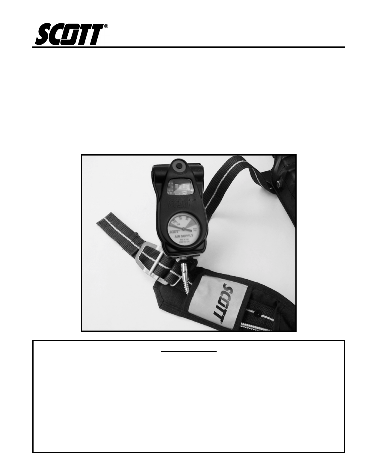
The SEMS PDA Control Console is integrated into the SCOTT AIRPAK SCBA as a part of the remote air pressure gauge which hangs
over the right shoulder of the respirator user. The Control Console
also operates the PERSONAL ALERT SAFETY SYSTEM (P ASS) distress alarm intended to assist in locating a respirator user who is incapacitated or in need of assistance. The Control Console has a set of
status lights, a four character digital display , a dial air pressure gauge,
and three control buttons which can easily be pressed with gloved
hands. Power is supplied by batteries in both the Control Console and
in the SEMS PDA distress alarm battery compartment on the SCBA
backframe.
2
NOTE
USE ONL Y IN ACCORDANCE WITH NFPA 1500,
"
STANDARD ON FIRE DEPARTMENT
OCCUPATIONAL SAFETY AND HEALTH
PROGRAM."
Page 3

The SEMS PDA
distress alarm warns the user when the air supply
cylinder has reached 50% of its full capacity and also functions as an
electronic end of service time indicator for the respirator by sounding
an alarm when the air supply cylinder has been depleted to 25% of its
full capacity. The Control Console digital display shows the approximate cylinder pressure. Details of the end of service time indicator
operation are also discussed in the Operation and Maintenance instructions provided with the respirator.
The SEMS PDR Base Station is a compact battery operated device
that can be tripod mounted or carried by a strap. A digital display
provides information about status of the respirator users who are logged
onto the Base Station. Simple dedicated function buttons control the
transmission and receipt of signals with the respirator users. The Base
Station can be easily interfaced with a computer for programming and
advanced applications.
When a respirator user opens the cylinder valve and begins use of an
AIR-PAK SCBA equipped with the SEMS PDA, the Portable Unit will
automatically begin to operate. If the SEMS PDR Base Station is
present at time of entry, the SEMS PDA must log-in with the Base
Station before entry into the hazardous area. Contact between the
SEMS PDA Portable Unit and the Base Station will continue until the
respirator user terminates use of the SCBA.
Each installation of SEMS equipment operates as a distinct set of
Portable Units and Base Station that transmit and receive on a single
frequency. If another installation of SEMS equipment is used in the
same area, the operation of each group will remain discreet and
separate between Portable Units and Base Stations. The SEMS
equipment operates between 453.0375 and 465.6375 MHz on radio
channels defined in FCC Title 47 (Telecommunications) Part 90 section 20, Limitation (27) and requirement Part 90.238. Programming
of the Portable Units and Base Station is essential and must be
performed prior to training and use. See SEMS Programming Guide,
SCOTT P/N 89506-01 for complete details of programming the SEMS
equipment.
The installation of the SCOTT SEMS PDA distress alarm is approved
by the National Institute of Occupational Safety and Health (NIOSH)
Fifty
on all models of SCOTT AIR-PAK 2.2 / 3.0 / 4.5 /
SCBA.
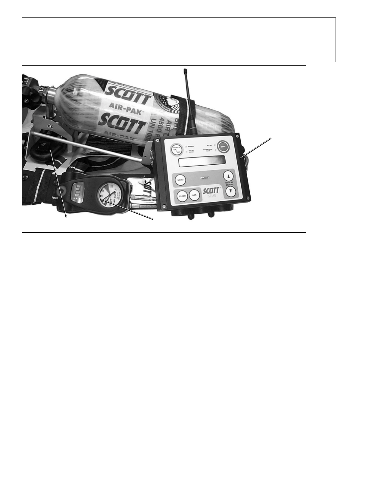
The SCOTT SEMS PDA distress alarm Portable Unit, when added to
a SCOTT Air-Pak respirator, as shown in FIGURE XX, consists of a
Sensor Module with battery compartment mounted to the bottom of
the respirator backframe, a pressure gauge with transducer, and a
Control Console mounted on the wearer’s right shoulder strap at the
pressure gauge location. The SEMS PDA Portable Unit requires three
(3) nine volt batteries to operate: two in the Sensor Module on the
backframe and one in the Control Console.
Installation of the SCOTT SEMS PDA distress alarm requires some
disassembly of the respirator and should only be performed by an
authorized service center. Contact SCOTT HEALTH AND SAFETY,
Monroe, NC at 1-800-247-7257 for details.
WARNING
NO PERSONAL ALERT SAFETY SYSTEM, RESPIRATOR OR COMBINATION OF PERSONAL
ALERT SAFETY SYSTEM AND RESPIRATOR,
BY THEMSELVES, CAN PROVIDE COMPLETE
PROTECTION IN FIRE SITUA TIONS. HOWEVER,
USING AN ALARM AND A RESPIRATOR IN
ACCORDANCE WITH THE REQUIREMENTS
OF AN ORGANIZED RESPIRAT OR Y PROTECTION PROGRAM IS ONE OF THE MANY
SAFETY PRECAUTIONS WHICH SHOULD BE
TAKEN TO AVOID PERSONAL INJURY OR
DEATH.
3
Page 4

DETECTING AND A VOIDING
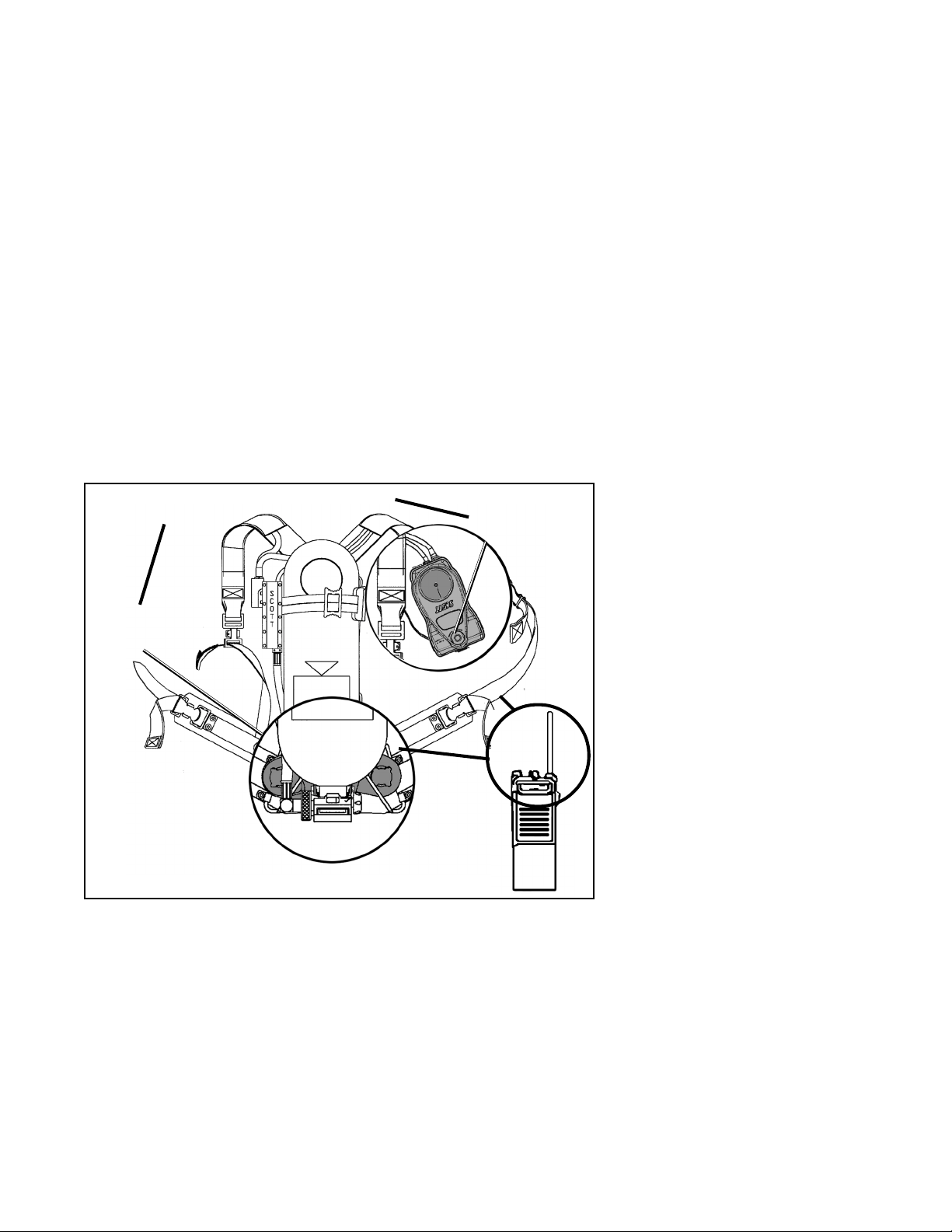
RADIO FREQUENCY INTERFERENCE:
When any electronic device is adversely affected by radio waves, Radio
Frequency Interference (RFI) is said to have occurred. All electronic
devices like the SEMS PDA distress alarm may be subject to the effects of RFI. Radio transmissions from the antennas of radios including those used by fire fighters, police and other public safety related
personnel may produce RFI in the SEMS PDA distress alarm. RFI
may occur while the radio is transmitting if the respirator equipped
with the SEMS PDA distress alarm is in close proximity to a base
station or high-powered vehicle mounted radio, or if the antenna of a
personal portable hand held radio is touching or within six (6) inches
of the Control Console or Sensor Module of the SEMS PDA distress
alarm (See FIGURE 4).
Be aware of the symptoms of RFI. A SEMS PDA distress alarm affected by RFI may temporarily give false indications such as the sudden sounding of the loud continuous three-tone chirp of the full alarm.
In some instances the lights on the Control Console may flash without
sounding the alarm. In rare circumstances, an alarm which was sounding may stop.
If the SEMS PDA exhibits any of the symptoms of RFI, identify the
source of the RFI and do the following:
· If the symptoms of RFI occur when standing near a base sta-
tion transmitting antenna or a truck mounted radio antenna,
move away from the antenna until the symptoms stop.
· If the symptoms of RFI occur while transmitting on a hand-
held radio, move the radio away from the SEMS PDA.
CHECK THE CONTROL CONSOLE AND BE CERT AIN THE GREEN
LIGHT IS FLASHING NORMALLY WHEN THE INTERFERENCE
STOPS, REGARDLESS OF THE SOURCE.
In normal usage with the air cylinder open, the SEMS PDA distress
alarm will typically resume normal operation after experiencing RFI.
In some circumstances after experiencing RFI, it may be necessary to
remove the unit from service. Remove and reinstall the battery to reset the unit (see BATTERY REPLACEMENT section of this instruction). Then inspect and return the unit to service.
W ARNING
KEEP THE ANTENNAS OF HAND-HELD
RADIOS AT LEAST SIX (6) INCHES AWAY
FROM THE CONTROL CONSOLE AND THE
SENSOR MODULE OF THE SEMS PDA
DISTRESS ALARM WHEN TRANSMITTING.
Close proximity of RADIO EQUIPMENT to the
SEMS PDA DISTRESS ALARM during radio
transmission may cause the unit to MALFUNCTION. FAILURE TO RECOGNIZE A MALFUNCTION OF THE SEMS PDA DISTRESS
ALARM AND TAKE THE PROPER CORRECTIVE
ACTION MAY RESULT A NONWORKING DISTRESS ALARM WHICH WILL NOT SOUND IF
THE USER STOPS MOVING AND LEAD TO SERIOUS INJURY OR DEATH.
W ARNING
USERS OF RESPIRATORS EQUIPPED WITH
THE SEMS PORTABLE UNIT MUST BE AW ARE
OF THE PROPER OPERATION OF THE
EQUIPMENT. FAILURE TO RECOGNIZE A
MALFUNCTION OF THE SEMS PORTABLE
UNIT AND TAKE PROPER CORRECTIVE ACTION
MAY RESULT IN SERIOUS INJURY OR DEATH.
4
Page 5
If the SEMS PDA distress alarm is affected by RFI when the respirator
air supply is turned off or the cylinder is empty, the distress alarm
could be turned off during use. If this occurs, depress the RED Manual
Alarm Button and hold at least two seconds to activate the alarm.
IF THE SYMPTOMS OF RFI OCCUR, THE RESPIRATOR USER
MUST CHECK THE SEMS PDA DISTRESS ALARM TO VERIFY THA T
IT IS FUNCTIONING PROPERLY. IF THE GREEN LIGHT ON THE
CONTROL CONSOLE DOES NOT RESUME FLASHING IN THE
NORMAL MANNER AFTER EXPERIENCING THE SYMPTOMS OF
RFI, OR IF THE UNIT CONTINUES TO MALFUNCTION IN ANY
OTHER WAY , PROCEED T O A SAFE AREA, REMOVE THE RESPIRA TOR FROM SERVICE AND TAG FOR REPAIR BY AUTHORIZED
PERSONNEL.
Minimize or eliminate the effects of RFI by protecting the SEMS PDA
with the following steps:
• Maintain a safe distance from a base station transmitting antenna
or a truck mounted radio antenna.
• Keep the antennas of hand held radios at least six (6) inches away
from the CONTROL CONSOLE or the SENSOR MODULE (See
FIGURE 2).
KEEP RADIO ANTENNAS A T LEAST
SIX (6) INCHES FROM THESE AREAS
SENSOR
MODULE
FIGURE 2
RFI WARNING AREAS
CONTROL
CONSOLE
WARNING
BE AWARE OF THE POTENTIAL EFFECT OF
RADIO TRANSMISSIONS FROM BASE STA TION
OR TRUCK MOUNT RADIOS WHEN USING A
RESPIRATOR WITH THE SEMS PDA DISTRESS
ALARM. Close proximity of RADIO EQUIPMENT
to the SEMS PDA DISTRESS ALARM during radio transmission may cause the unit to MALFUNCTION. FAILURE TO RECOGNIZE A MALFUNCTION OF THE SEMS PDA DISTRESS
ALARM AND TAKE THE PROPER CORRECTIVE
ACTION MAY RESULT A NONWORKING DISTRESS ALARM WHICH WILL NOT SOUND IF THE
USER STOPS MOVING AND LEAD TO SERIOUS
INJURY OR DEATH.
5
Page 6

FCC NOTICE
This equipment has been tested and found to comply with the requirements of United States Federal Communications Commission,
Code of Federal Regulations, FCC title 47, part 90 Section 20, limitation (27) and requirement Part 90.238 over frequency range 453.0375
to 465.6375 MHz, as well as FCC Section 1.1310 for Occupational/
Controlled Exposure limits.
If the SEMS Base Station or Portable Unit has been damaged, DO
NOT use this equipment. Maintenance or repair of this equipment
must only be performed by an authorized SCOTT service center.
Unauthorized service may void the manufacturers warranty and may
cause damage to the equipment. Use only Scott authorized accessories, cables, and power connectors. Consult the operating and service manuals for instructions on battery replacement, battery maintenance, and use of accessory cables.
RADIO FREQUENCY INTERFERENCE (RFI)
When any electronic device is adversely affected by radio waves, Radio Frequency Interference (RFI) is said to have occurred. All electronic devices like the SEMS PDA distress alarm may be subject to the
effects of RFI, most of which are temporary in nature. Users of the
SCOTT AIR-P AK SCBA with the integrated SEMS PDA distress alarm
must be familiar with the normal operation of the distress alarm and
must also be familiar with how to identify and avoid the effects of RFI
(see DETECTING AND A VOIDING RADIO FREQUENCY INTERFERENCE on page 14). If RFI occurs to the SEMS PDA distress alarm, it
may be caused by transmissions from two-way radio base stations or
high-powered vehicle mounted radios or transmissions from hand-held
or personal radios where the radio antenna is touching or very close to
(less than 6 inches from) components of the SEMS PDA distress alarm.
INTRINSICALL Y SAFE LISTING
The SEMS PDA distress alarm, when installed on a SCOTT respirator,
is listed as intrinsically safe in Class I Division 1 Groups A, B, C and D
hazardous locations by Entela Testing Laboratories. T o maintain Intrinsic Safe Listing, the respirator with SEMS PDA distress alarm must be
inspected regularly per the following Regular Operational Inspection
procedures. SEMS PDA distress alarm components must not be tampered with in any manner. Only batteries of the type indicated on the
Sensor Module label and in the Battery Replacement instructions may
be installed. The battery compartments must only be opened in an
area known to be free of flammable or explosive hazards.
PROGRAMMING
Before SEMS equipment can be put into service, the Base Station and
each Portable Unit must be programmed to work with each other. The
amount and detail of the information programmed in will depend on the
requirements of the organization using the SEMS. At a minimum, the
equipment must be setup so that the Base Station will recognize each
Portable Unit in the group and associate an identity of the respirator
user with the Portable Unit. In this way, specific users who have entered a particular region of the hazardous area can be contacted individually to evacuate to a safe atmosphere. In addition, if a Portable Unit
transmits a DISTRESS SIGNAL, the Base Unit will display the identity
of the respirator user. See SEMS Programming Guide, SCOTT P/N
89506-01 for complete details of programming the SEMS equipment.
W ARNING
RADIO FREQUENCY INTERFERENCE (RFI)
MA Y CAUSE A MALFUNCTION OF THE SEMS
PDA DISTRESS ALARM. USERS OF RESPIRATORS EQUIPPED WITH THE SEMS PDA
DISTRESS ALARM MUST BE AW ARE OF THE
PROPER OPERATION OF THE DISTRESS
ALARM. FAILURE TO RECOGNIZE A MALFUNCTION OF THE SEMS PDA DISTRESS
ALARM AND TAKE PROPER CORRECTIVE
ACTION MAY RESULT IN SERIOUS INJURY OR DEATH.
6
Page 7

BASIC FUNCTIONS OF THE SEMS EQUIPMENT
The SEMS equipment has two primary functions:
· Personal Alert Safety System (PASS) Distress Alarm
· Evacuation Signal
1. The PASS Distress Alarm is joined to the SEMS PDA distress
alarm operation. The Portable Unit will send a signal to the Base
Station when the SEMS PDA distress alarm goes into full alarm.
Activation of the full alarm can be either by manual activation of
the user or by automatic activation from lack of user movement
for the time period set on the SEMS PDA distress alarm. Once
acknowledged by the Base Station operator, “PASS” will appear
on the Control Console display.
2. The Evacuation Signal is sent from the Base Station to the SEMS
PDA Portable Unit. It can be handled one of two ways:
a) All-Call Signal: The Base Station will send a signal to all SEMS
PDA Portable Units logged on to it. When received, the Control Console will display “EVAC” and sound an audible signal.
Every respirator user must acknowledge this signal by press-
twice
ing
will continue to read “EVAC” until user leaves hazardous area
and shuts down the respirator.
b) Selective Evacuation Alarm The Base Station will send a sig-
nal to only one individual unit logged on to it. When received,
the Control Console will display “EVAC” and sound an audible
alarm. The selected respirator user must acknowledge this signal by pressing
sole. Display will continue to read “EVAC” until user leaves
hazardous area and shuts down the respirator.
the RESET button on the Control Console. Display
twice
the RESET button on the Control Con-
Other additional functions include:
1. The Contact Signal is an automatic signal sent by the Base Sta-
tion to every Portable Unit that is logged in to the Base Station.
Any respirator user who does not return an acknowledgment to
the Contact Signal within 120 seconds will be shown on the Base
Station as “OUT OF RANGE.”
2. Air supply cylinder levels are monitored by the Portable Unit and
the Base Station. The user can press and hold the RESET button at any time for a digital display of the remaining air supply
cylinder pressure. The approximate cylinder pressure is displayed.
The user receives a “½ AIR” warning in the display with an audible alarm when the cylinder reaches one-half of full pressure.
The user also receives a “LOW AIR” warning in the display with
an audible alarm when the cylinder reaches one quarter of full
pressure. The “LOW AIR” warning is also transmitted to the Base
Station. The “LOW AIR” alarm will continue to operate until the
respirator is shut down.
3. Users can inform the Base Station that they are withdrawing from
the hazardous atmosphere by pressing and holding the “WITHDRAW” button on the Control Console for at least two seconds.
The display will read “W–D” until the user leaves the hazardous
area and shuts down the respirator.
7
Page 8
OPERA TION OF THE SEMS PDA DISTRESS ALARM
With proper batteries installed and a charged air cylinder, the SEMS
PDA distress alarm (PASS) is automatically activated when the respirator is pressurized by opening the cylinder valve of the respirator. If
batteries are completely discharged or have not been installed, there
will be no light or sound indicating that the unit will not work at all.
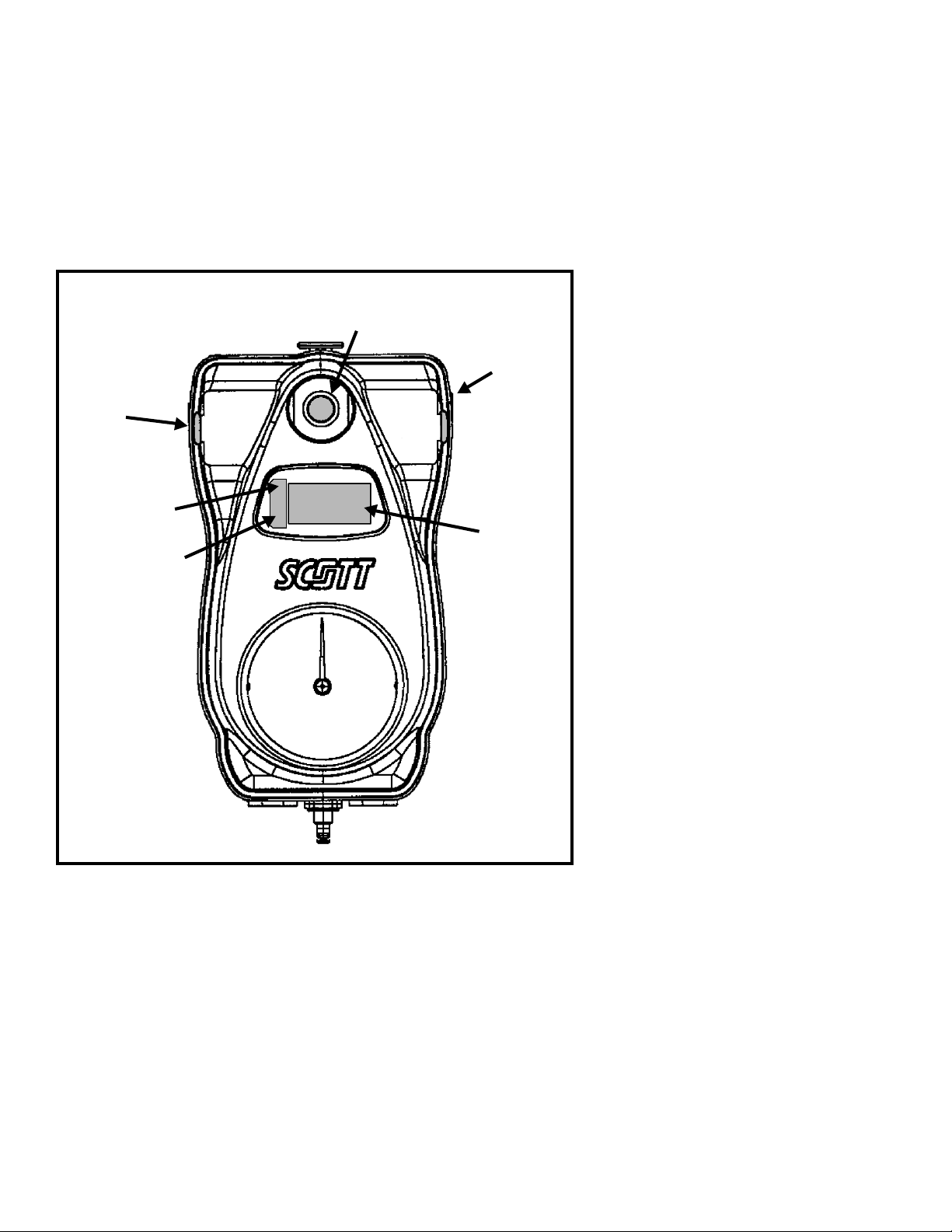
Activation is indicated by 3 quick audible chirps from the Sensor Module. On activation, a green light located on the Control Console, shown
in FIGURE 3, will begin to flash approximately once a second. The
SEMS PDA distress alarm is now in the automatic mode.
MANUAL
WITHDRAW
BUTTON (BLUE
INDICATOR)
RED SIGNAL
LIGHT
GREEN SIGNAL
LIGHT
WITHDRAW
ALARM BUTTON
(RED INDICAT OR)
MANUAL
ALARM
RESET
RESET
BUTTON
(YELLOW
INDICATOR)
CONSOLE
DISPLAY
W ARNING
THE SEMS PDA DISTRESS ALARM IS INTENDED TO ASSIST IN LOCATING A PERSON WHO MAY BE IN A LIFE THREATENING SITUATION. FAILURE TO FOLLOW
THE INSTRUCTIONS FOR OPENING,
CHANGING ALL BATTERIES AND RE-CLOSING BOTH B ATTERY COMPARTMENTS MAY
RESULT IN DAMAGE WHICH COULD CAUSE
FAILURE OF THE PASS DURING A LIFE
THREATENING EMERGENCY OR COULD
CAUSE A FIRE OR EXPLOSION IN A FLAMMABLE OR EXPLOSIVE ATMOSPHERE POSSIBLY RESULTING IN SERIOUS INJURY OR
DEATH.
W ARNING
USERS OF RESPIRATORS EQUIPPED WITH
THE SEMS PDA DISTRESS ALARM MUST BE
AWARE OF THE PROPER OPERATION OF
THE DISTRESS ALARM. FAILURE TO RECOGNIZE A MALFUNCTION OF THE SEMS PDA DISTRESS ALARM AND TAKE PROPER CORRECTIVE ACTION MA Y RESULT IN SERIOUS INJURY OR DEATH.
FIGURE 3
THE PORTABLE UNIT
If the any of the batteries needs replacement, the SEMS PDA distress
alarm will indicate as follows:
• SENSOR MODULE – A single audible chirp from the Sensor Module once every 2 seconds and the green light on the control module will not flash.
• CONTROL CONSOLE – “BATT” will appear in the display but all
other functions will operate normally.
If any low battery condition appears at start-up, immediately change
all the batteries before use of the respirator. See the BATTERY REPLACEMENT section of this instruction. If a low battery condition appears while the respirator is in use, the SEMS PDA distress alarm will
continue to operate for a period of time greater then the longest duration cylinder available for the respirator.
8
Page 9

Once activated, the SCOTT SEMS PDA distress alarm will remain
activated until:
1. The respirator air cylinder is turned off with the residual air pres-
sure purged from the regulator
AND
2. The reset button on the control module has been pressed twice.
In the automatic mode the SCOTT SEMS PDA distress alarm con-
stantly monitors motion of the respirator backframe. The motion sensor is located in the Sensor Module along with the audible alarm. If
the Sensor Module does not sense motion of the respirator for 20
seconds the SEMS PDA distress alarm will signal a pre-alarm condition. If there is still no motion of the respirator for the next 12 seconds
the full alarm will sound.
PRE ALARM:
Once the respirator is pressurized, the SEMS PDA distress alarm will
automatically sound a pre-alarm if the respirator remains motionless
for more than 20 seconds.
When the pre-alarm occurs, the green flashing lights on the Control
Console and backframe are replaced by bright red lights which flash
approximately once a second and are accompanied by an ascending/
descending audible tone which increases in volume during the prealarm cycle.
If the user is
not incapacitated or not in need of assistance, the prealarm is normally reset by movement of the respirator. When reset,
the flashing red lights will be replaced by the flashing green lights and
the ascending/descending tone will stop.
A pre-alarm may also be reset by pressing and holding the reset button on the side of the Control Console until three (3) quick audible
chirps are heard and the red flashing lights on the Control Console
and backframe are replaced by the green flashing lights.
Remember that the motion sensor is in the Sensor Module under the
air cylinder valve and not in the Control Console so that actual movement of the respirator backframe is required for reset. Shaking the
Control Console
will not reset the SEMS PDA distress alarm .
WARNING
USERS OF RESPIRATORS EQUIPPED WITH
THE SEMS PDA DISTRESS ALARM MUST BE
AWARE OF THE PROPER OPERATION OF
THE DISTRESS ALARM. IF THE GREEN LIGHT
IS NOT FLASHING NORMALL Y, OR IF THE UNIT
EXHIBITS ANY OTHER SIGNS OF A MALFUNCTION WITHOUT THE USER TAKING PROPER
CORRECTIVE ACTION, IT MAY LEAD TO CIRCUMSTANCES THAT RESULT IN SERIOUS INJURY OR DEATH.
FULL ALARM:
If the user is incapacitated or in need of assistance and can not move,
the SEMS PDA distress alarm will go into full alarm 12 seconds after
the pre-alarm starts.
Full alarm is indicated by a loud, almost continuous 3 tone chirp from
the Sensor Module accompanied by the flashing of the red signal lights
on the Control Console and “PASS” will appear in the display . The full
alarm condition can only be cleared by manually pressing twice on the
reset button, located on the side of the Control Console, shown in
FIGURE 3.
After the full alarm has been silenced by pressing the reset button,
releasing it and pressing it again, the SEMS PDA distress alarm will
remain activated with the green lights flashing once every 2 seconds.
In the activated or “automatic” mode, it will again go into pre-alarm
followed by full alarm unless there is movement of the respirator at
least once every 20 seconds as long as the respirator is pressurized.
9
Page 10

MANUAL ALARM:
If the respirator user is in a situation where immediate assistance is
required, the SEMS PDA distress alarm provides a manual alarm button, located on the front of the Control Console on the user’s right
shoulder, shown in FIGURE 2.
The manual alarm causes the Full Alarm signal to be given. The
manual alarm may be activated at any time by pressing the manual
alarm button and holding at least two seconds, even when the respirator is not pressurized, provided a good battery is in the SEMS PDA
distress alarm. If the manual alarm button has been pressed without
the respirator pressurized, the alarm can be silenced by pressing the
reset button twice. The SEMS PDA distress alarm is now on and in
automatic mode. To turn the unit off, press the reset twice again while
the unit is not in alarm mode.
TURNING OFF THE SEMS PDA DISTRESS ALARM:
The SEMS PDA distress alarm can not be turned off if the respirator
cylinder valve is open and/or pressure remains in the respirator . Pressing the reset button when the respirator is pressurized will only reset
an alarm condition and return the SEMS PDA distress alarm to automatic mode.
When the use of the SEMS PDA distress alarm and respirator is no
longer required, first close the cylinder valve on the respirator, then
vent the residual air from the respirator system by opening the regulator purge valve. After waiting until the air flow stops, close the regulator purge valve and turn off the SEMS PDA distress alarm by pressing
the reset button twice after the flashing green light sequence. The
unit will say “OFF” in the display , sound a quick two tone chirp, and the
SEMS PDA distress alarm will be inactive. If there is no pressure in
the system when the reset button is pressed twice, there will be no
beep sequence.
If the respirator is turned off and depressurized without pressing the
reset button twice, the SEMS PDA distress alarm will continue to monitor motion in automatic mode. This means that the SEMS PDA distress alarm may be used to monitor motion after the respirator is turned
off and depressurized. Resetting the full alarm after the respirator has
been depressurized
will not turn off the SEMS PDA distress alarm.
The reset switch must be depressed twice after the flashing green
light sequence with no alarm condition to turn off the SEMS PDA distress alarm (the display will say “OFF” and two tone chirp should be
heard).
Remember, the loud audible alarm and flashing red lights can be turned
on at any time by pressing the manual alarm button and holding at
least two seconds.
W ARNING
NO PERSONAL ALERT SAFETY SYSTEM, RESPIRATOR OR COMBINATION OF PERSONAL
ALERT SAFETY SYSTEM AND RESPIRATOR,
BY THEMSELVES, CAN PROVIDE COMPLETE
PROTECTION IN FIRE SITUA TIONS. HOWEVER,
USING AN ALARM AND A RESPIRATOR IN
ACCORDANCE WITH THE REQUIREMENTS
OF AN ORGANIZED RESPIRAT OR Y PROTECTION PROGRAM IS ONE OF THE MANY
SAFETY PRECAUTIONS WHICH SHOULD BE
TAKEN TO AVOID PERSONAL INJURY OR
DEATH.
10
Page 11

OTHER OPERA TIONAL FEA TURES
END OF SERVICE TIME INDICATOR
The SEMS PDA
distress alarm also provides an electronic end of ser-
vice time indicator and cylinder pressure display as follows:
1/2 full cylinder
When the air supply cylinder has reached 1/2 full capacity, the
audible signal will sound and the display will read “1/2 AIR” for 10
seconds.
1/4 full cylinder
When the air supply cylinder has reached 1/4 full capacity, the
audible signal will sound and the display will read “LOW AIR” and
then flash the remaining cylinder air pressure in psig until the user
responds by pressing the RESET button. However, the alarm will
continue to repeat actuation until the system is shut down or until
the unit detects no movement by the user at which time the SEMS
PDA distress alarm sequence will begin with PRE ALARM and
FULL ALARM as stated above.
Cylinder pressure display
Pressing and holding the RESET at any time will show the approximate cylinder pressure remaining in psig on the display.
WARNING
THE RESPIRATOR USER MUST IMMEDIATELY LEAVE THE AREA REQUIRING
RESPIRATORY PROTECTION WHEN AN
END OF SERVICE INDICATOR ALARM
ACTUATES. ACTUATION OF AN END OF
SERVICE INDICATOR ALARM WARNS
THAT APPROXIMATELY 25% OF FULL
PRESSURE REMAINS IN THE AIR SUPPLY
CYLINDER (THAT IS, APPROXIMATELY
3/4 OF THE TOTAL AIR SUPPLY HAS
BEEN USED). A DELAY IN LEAVING THE
AREA AFTER ALARM ACTUATION MAY
RESULT IN SERIOUS INJURY OR
DEATH.
BA TTERY TEST
When the SEMS PDA distress alarm is in the off condition (cylinder
valve closed with no flashing green lights, the batteries in the Sensor
Module can be checked by depressing and holding the reset button
on the console.
A green LED will illuminate on the console to indicate sufficient battery
power remaining; a red light indicates that the batteries must be replaced before the respirator is to be used again.
WARNING
FAILURE TO REPLACE THE BATTERIES AND/
OR CONTINUING WITH MULTIPLE USES OF
THE RESPIRATOR AFTER THE LOW BATTERY CONDITION HAS BEEN INDICATED BY
THE SEMS PDA DISTRESS ALARM MAY RESULT IN FAILURE OF THE SEMS PDA DISTRESS ALARM DURING USE AND POSSIBLE INJURY OR DEATH OF THE USER.
11
Page 12

USE OF THE SEMS PDA PORT ABLE UNIT
Users of SCOTT respirators equipped with the SEMS PDA Portable
Unit must be fully trained in the operation of the equipment as part of
a complete respiratory protection program before entering a hazardous environment.
1. Start-up
a) Use of the SEMS PDA Portable Unit begins when the user
opens the cylinder valve on the respirator to start respirator
usage. The unit will sound three chirps to indicate activation.
b) After a brief start-up sequence of less than ten seconds, the
green light in the Control Console and the display will show
“<<<<“ until the unit is acknowledged and logged onto a base
station. An alert tone, a “BE-doop” to indicate the system activity, is used for several functions. Whenever the alert tone
occurs, the user should look at the Portable Unit display for
information.
2. Initialization and Range
a) After the start-up sequence, the SEMS PDA Portable Unit will
send an Initialization signal to the Base Station to log in. The
Base Station will respond by showing “ACK” for the identity
assigned to that Portable Unit.
b) If the respirator user moves too far from the Base Station after
logging-in, the Control Console will begin to display “RNGE”
indicating out of range until the user moves back into the Base
Station field of operation (up to one-half mile line-of-sight).
c) If the Portable Unit is too far away from the Base Station at
start-up, or if the Base Station is not powered up, the Control
Console display will read “RNGE” right from start-up and not
be logged into the Base Station. The SEMS PDA Portable Unit
will continue trying to log-in to a Base Station until one comes
into range or is powered up.
d) Except for those functions which involve communication with
the Base Station, all other functions of the Control Console
and SEMS PDA distress alarm are still operational when the
Portable Unit is either out of range or not logged into a Base
Station.
3. Air Supply Cylinder Pressure
a) To check the air supply cylinder pressure, the user must press
and hold the RESET button on the Control Console. The approximate pressure remaining in the cylinder will be shown in
the display as PSIG.
b) When the cylinder reaches one-half of full pressure, the Con-
trol Console will display “1/2 AIR” for ten seconds.
c) When the cylinder reaches one-quarter of full pressure, the
Control Console will display “LOW AIR”. A low air signal will be
sent to the Base Station within ten seconds. The Base Station
operator must press “ACK” on the Base Station to acknowledge the user’s low air signal.
W ARNING
USERS OF RESPIRATORS EQUIPPED WITH
THE SEMS PDA DISTRESS ALARM MUST BE
AWARE OF THE PROPER OPERATION OF
THE DISTRESS ALARM. FAILURE TO RECOGNIZE A MALFUNCTION OF THE SEMS PDA DISTRESS ALARM AND TAKE PROPER CORRECTIVE ACTION MA Y RESULT IN SERIOUS INJURY OR DEATH.
12
Page 13

4. Distress Alarm
a) If the user is in distress or becomes immobile, the SEMS PDA
distress alarm will operate in conjunction with the Portable Unit.
If the distress alarm is activated, either by the user pressing
and holding the MANUAL ALARM for at least two seconds, or
from the user being immobile for the required time duration,
the Portable Unit will send a distress signal to the Base Station. The distress alarm will override all other messages and
actions of the Portable Unit.
b) When the Base Station acknowledges the user’s distress sig-
nal by pressing the “ACK” button on the Base Station, the Control Console will respond by displaying “PASS” and continuing
to sound the distress alarm on the respirator. The distress alarm
will continue until the user shuts down the respirator.
5. Evacuation
a) If the respirator users are required to leave the hazardous area,
the Base Station operator can send an evacuation message to
the Portable Units of logged-in respirator users. This message
can be sent either to all logged-in users or to selected loggedin users as chosen from the list on the Base Station.
b) The Portable Unit will emit the alert sound and “EVAC” will
appear flashing in the Control Console display.
c) When an “EVAC” message appears on the Control Console
twice
display, the respirator user must press
the RESET button on the Control Console to respond to the evacuation message. “EVAC” will continue to appear in the display of the Control Console until the user leaves the hazardous area and shuts
down the respirator.
6. Withdraw
a) The respirator user may choose to leave the hazardous area.
Pressing and holding the WITHDRAW button on the Control
Console will send that message to the Base Station.
b) When the Base Station receives a user withdrawal message,
the operator presses the “ACK” button on the Base Station to
respond.
c) When the Portable Unit receives the acknowledgment re-
sponse, the Control Console will display “W–D” until the respirator user leaves the hazardous area and shuts down the respirator.
7. Shutdown
a) After leaving the hazardous area and confirming that respira-
tor use is no longer required, doff the respirator according the
user instructions provided with the respirator.
b) Close the cylinder valve.
c) Press the RESET button twice.
d) The Control Console will sound the alert tone and flash “OFF”
in the display. The Portable Unit is now off.
8. Batteries
Battery operation is as stated in the SEMS PDA distress alarm
section of this instruction.
WARNING
IF THE LOW BATTER Y INDICA TION OCCURS A T
ANY TIME DURING USE OF THE RESPIRA T OR,
THE BATTERIES MUST BE CHANGED BEFORE
THE NEXT USE OF THE RESPIRA TOR. USE OF
A RESPIRATOR WITH DEPLETED BATTERIES
MAY LEAD TO A FAILURE OF THE RESPIRATOR WHICH COULD RESULT IN SERIOUS INJURY OR DEATH.
13
Page 14

USE OF THE SEMS BASE ST ATION
The SEMS PDR Base Station must be properly programmed before
field use. See SEMS Programming Guide SCOTT P/N 89506-01 for
complete details of SEMS programming.
The SEMS PDR Base Station requires batteries for operation. See the
BA TTER Y REPLACEMENT section of this instruction. An optional external power supply is available.
The SEMS PDR Base Station must be operated by a fully trained individual as part of a complete respiratory protection program. The Base
Station operator must have the ability to direct rescue operations as
needed.
1. Start-up
a) Press the POWER button on the Base Station to begin opera-
tion.
b) All Portable Units that were initialized before the Base Station
was powered up will be logged-in as indicated by “ACK” registered with the user’s identity.
c) Any Portable Units initialized after the Base Station is powered
up will also be logged-in as indicated by “ACK” registered with
the user’s identity.
d) The base station tracks the time for each Portable Unit from
log-in until each respirator user leaves the hazardous area and
shuts down their respirator.
W ARNING
THE SEMS BASE STATION MUST BE MONITORED BY A FULLY TRAINED INDIVIDUAL
WITH THE ABILITY TO DIRECT RESCUE OPERATIONS AT ALL TIMES WHEN LOGGED-IN
RESPIRAT OR USERS MA Y BE IN A HAZARDOUS
AREA. FAILURE TO PROVIDE A PROPERLY
TRAINED BASE STATION OPERATOR MAY
PERMIT A SITUATION TO OCCUR WHICH
COULD RESULT IN SERIOUS INJURY OR
DEATH.
POWER
BUTTON
MENU
BUTTON
EV AC
BUTTON
NORMAL
POWER EVAC
OUT OF
RANGE
DIGIT AL DISPLAY WINDOW
MENU
CLEAR
CLEAR
ACK
ACKNOWLEDGE
BUTTON
EXT
DC
LOW
BATT
ALARM
BUTTON
FIGURE 4
BASE ST A TION
ALARM
LIGHT
SCROLL
BUTTONS
14
Page 15

2. Evacuation
a) To send an evacuation message to all logged-in respirator us-
ers, the Base Station operator must press and hold the “EVAC”
button on the Base Station and then choose “ALL-CALL” from
the menu on the display. The “EVAC message will be sent to
all logged-in respirator users.
b) To send an evacuation message to only selected respirator
users, the Base Station operator uses the scroll buttons to move
up and down the list of logged-in respirator users and presses
the “EVAC” button when the selected users are highlighted in
the display.
c) The respirator users who receive the “EVAC” message must
press the RESET button on the Control Console to acknowledge the message.
d) The Base Station listing of logged-in users will display “CONF”
with each respirator user who has responded to the “EVAC”
message.
3. Air Supply Monitoring
a) When the air supply cylinder reaches one-quarter of full pres-
sure, the alert sound will occur and the Control Console will
display “LOW AIR”. A low air signal will be sent to the Base
Station within ten seconds. This end of service time indicator
(EOSTI) alarm cannot be silenced by the user until the user
leaves the hazardous area and shuts down the respirator.
b) The Base Station operator must press “ACK” on the Base Sta-
tion to acknowledge the user’s low air signal.
15
Page 16

EVENT LOG
Software within the Base Station maintains a data record or EVENT
LOG of each communication to or from the Base Station from the time
it is powered for use unitl it is powered down. To acces and use the
EVENT LOG, proceed as follows:
BASE UNIT INTERF ACE SETUP
Plug the Base Unit Interface Cable into a COM port as instructed in
the COMPUTER SETUP section the SEMS Programming Instructions SCOTT P/N 89506-01.
1. Plug the other end of the Base Unit Interface Cable into the connector on the side of the Base Unit.
2. Run the SEMS Fire Department Software and select the tab labeled
“EVENT LOG.” See FIGURE 5.
FIGURE 5
EVENT LOG SCREEN
3. On the Base Unit, press and hold the EVAC button while turning
on the unit by pressing the POWER ON/OF button. Continue holding the EV AC button until the screen displays, “COMMAND MODE:
CS =0X2A58”. (NOTE: CS number may vary depending on version of Base Unit.)
4. Choose either “SAVE” or “SAVE & PURGE” to save the information in the EVENT LOG. The data will be saved as a text (.txt) file
to a folder called “Event Logs” in the same folder where the SEMS
Fire Department Software resides on your computer
[e.g.:(drive)\Program Files\SEMS Service Center\Event
Logs\(folder)].
a) “SAVE” will save the EVENT LOG file to the Event Logs folder
but leaves the EVENT LOG information on the Base Unit.
b) “SAVE & PURGE” will save the EVENT LOG file to the Event
Logs folder and then erase the EVENT LOG information from the
Base Unit.
16
Page 17

5. The EVENT LOG file is a text (.txt) which may be viewed in either
Microsoft Excel or Microsoft Word. The data is in columns separated (delimited) by commas. It may require some manipulation
of the columns to facilitate reading as shown in FIGURE 6. The
columns contain information as follows:
Column 1 Event number Identification
Column 2 Date of Event
Column 3 Time of Event
Column 4 Fire Company (blank if the PDA and the Base Unit have
the same name.)
Column 5 Truck Number
Column 6 Seat Number or Position
Column 7 Event (LOGON, PASS, ACK, etc.)
Column 8 Cylinder Pressure at time of Event
Column 9 Total time the AIR-P AK respirator had been on at time
of Event
FIGURE 6
SAMPLE EVENT LOG
Columns 4, 5, and 6 identify a particular AIR-PAK respirator
equipped with the SEMS PDA that has logged on to the Base Unit
in the course of the incident. The events include LOGON, PASS
activation, Withdrawal, Acknowledgement (ACK) of of messages,
etc.
17
Page 18

REGULAR OPERA TIONAL INSPECTION
When installed on a SCOTT SCBA, inspection and test of the SCOTT
SEMS PDA distress alarm is to be conducted along with inspection
and test of the respirator before each use. To do this, the REGULAR
OPERATIONAL INSPECTION procedures in your respirator instructions will require modification. The instructions below are to be added
to the instructions for REGULAR OPERA TIONAL INSPECTION of your
respirator. If, during the inspection, any malfunction of the respirator
or the SEMS PDA distress alarm is noted remove the respirator from
service and tag for repair by authorized personnel.
REGULAR OPERA TIONAL INSPECTION of the SEMS PDA Portable
unit installed on a SCOTT SCBA requires inspection of both the Distress Alarm (P ASS) functionality and the Portable Unit interaction with
the SEMS PDR Base Station.
Before REGULAR OPERA TIONAL INSPECTION, verify that the batteries are fresh and properly installed. Batteries are located in two
locations on the SEMS PDA distress alarm Portable Unit. Each location notifies separately when the batteries require replacement:
• As the batteries in the Sensor Module begin to approach the end
of their useful life, the Sensor Module will sound a chirp approximately every two seconds, the green lights on the control module
will go out.
• When the battery in the Control Console requires changing, “BATT”
will appear in the display .
In either condition the SEMS PDA distress alarm will continue to operate normally, going into pre-alarm after 20 seconds with no motion
and full alarm after 12 more seconds of no motion.
While in a low battery condition, the SEMS PDA distress alarm will
continue to operate for a period of time greater then the longest duration cylinder available for the respirator. However, the batteries must
be replaced before the respirator is used again. See BATTERY REPLACEMENT section of these instructions.
BA TTERY TEST
When the SEMS PDA distress alarm is in the off condition (cylinder
valve closed with no flashing green lights, the batteries in the Sensor
Module can be checked by depressing and holding the reset button
on the console.
A green LED will illuminate on the console to indicate sufficient battery
power remaining; a red light indicates that the batteries must be replaced before the respirator is to be used again.
W ARNING
FOLLOW REGULAR OPERATIONAL INSPECTION PROCEDURE EXACTLY. IF THE SEMS
PDA DISTRESS ALARM DOES NOT ACTUATE, OR DOES NOT OPERATE AS DESCRIBED OR IF ANY OTHER OPERATIONAL
MALFUNCTION IS NOTED, DO NOT USE THE
RESPIRATOR.
W ARNING
FAILURE TO REPLACE THE BATTERIES AND/
OR CONTINUING WITH MULTIPLE USES OF
THE SEMS EQUIPMENT AFTER THE LOW
BATTERY CONDITION HAS BEEN INDICATED MAY RESULT IN FAILURE OF THE
SEMS ACCOUNTABILITY SYSTEM DURING
USE WHICH COULD LEAD TO SERIOUS INJURY OR DEATH.
W ARNING
IN SEVERAL OF THE INSPECTION PROCEDURES DESCRIBED A FULL ALARM WILL
BE OBSERVED. THE FULL ALARM CONDITION INCLUDES AN AUDIBLE TONE THAT
CAN EXCEED 95 dBA AT 3 METERS (9.9 FT.).
IN ORDER TO PREVENT POSSIBLE HEARING DAMAGE DURING TEST, THE ALARM
SHOULD BE RESET IMMEDIATELY ON VERIFICATION THAT
ERLY. HEARING PROTECTION SHOULD BE
WORN IF PROLONGED EXPOSURE TO A
FULL ALARM CONDITION IS ANTICIPATED.
EMS
IS FUNCTIONING PROP-
CAUTION
THE PERFORMANCE PROPERTIES OF THE
SEMS PDA DISTRESS ALARM CANNOT BE
PROPERLY TESTED IN THE FIELD.
NOTE
IF THIS INSPECTION IS DONE IN DIRECT SUNLIGHT IT MAY BE HELPFUL TO SHADE THE
LENS ON THE CONTROL MODULE WITH YOUR
HAND TO BE SURE THE GREEN LIGHT IS
FLASHING.
18
Page 19

INSPECTION OF SEMS PDA DISTRESS ALARM
1. While performing the visual inspection of the respirator visually
inspect all SEMS PDA distress alarm enclosures, lenses, and wire
conduits for cracks, wear or other damage. If damage is noted,
remove respirator from service and tag respirator for repair by
qualified personnel.
2. Before pressurizing the respirator by opening the cylinder valve,
check the SEMS PDA distress alarm manual alarm feature by
pressing the manual alarm button, located on the front of the Control Console. Press and hold the manual alarm button at least two
seconds. The manual alarm shall begin sounding a loud almost
continuous 3 tone chirp accompanied by flashing of the red signal
light on the Control Console and backframe. Reset the manual
alarm by pressing twice on the reset button located on the side of
the Control Console (fully depress reset button, release and
press again). Unit will sound three chirps and green light will flash.
Turn the unit off by pressing the reset button twice again. Unit will
sound a two tone chirp and green lights will go out.
3. Open the cylinder valve to pressurize the system. The SEMS PDA
distress alarm shall sound 3 quick chirps and the lights on the Control Console and backframe shall begin flashing green about once
a second. The 3 chirps will sound approximately the same time the
VIBRALERT® in the mask mounted regulator actuates briefly.
4. Check pre-alarm: With respirator pressurized but with air flow
stopped (with switch depressed on “donning switch” or “E-Z FLO™”
regulators or with facepiece held to face on standard models),
leave respirator motionless for 20 seconds. The green flashing
lights shall be replaced by red flashing lights. An ascending/descending tone will sound increasing in volume.
5. Check pre-alarm reset: With respirator pressurized but with air
flow stopped (see step 4 above) leave respirator motionless until
pre-alarm condition occurs. Within 12 seconds, move the respirator to activate the Sensor Module. SEMS PDA distress alarm shall
reset. The red flashing lights shall be replaced by green flashing
lights and the ascending/descending tone shall stop.
Continue with regular operational inspection of respirator as directed by respirator instructions or your approved respiratory protection plan procedure. During the inspection the respirator must
be moved or turned every 30 seconds or less to prevent the sounding of the full alarm.
Perform the following checks after completion of all respirator checks and before turning off cylinder valve:
6. Check manual reset of pre-alarm: With respirator pressurized but
with air flow stopped (see step 4 above) leave respirator motionless until pre-alarm condition occurs. Within 12 seconds press
and hold reset button. Three (3) chirps shall sound, then release
button. The SEMS PDA distress alarm shall reset to the automatic
mode and the flashing red lights will be replaced by a flashing
green lights.
7. Check full alarm: Again, as in step 6 above, leave respirator mo-
tionless until pre-alarm condition occurs. Do not reset. Within 12
seconds a loud, almost continuous 3 tone chirping shall begin,
accompanied by the flashing of the red lights on the Control Console and backframe. Display will read “PASS.”
19
WARNING
IF THE LOW BATTERY INDICATION (ONE
STEADY CHIRP EVERY TWO SECONDS
WITH NO FLASHING LIGHTS) OCCURS AT
ANY TIME DURING REGULAR OPERATIONAL
INSPECTION, DO NOT USE THE RESPIRAT OR.
CHANGE THE BATTERY IN THE BATTERY
COMPARTMENT IMMEDIATELY AND REPEAT THE REGULAR OPERATIONAL TEST
OR T AKE THE RESPIRA T OR OUT OF SERVICE
UNTIL THE BATTERY IS CHANGED AND THE
REGULAR OPERATIONAL TEST IS SUCCESSFULLY PERFORMED.
WARNING
IF THE SEMS PDA DISTRESS ALARM IS
USED IN AN AREA OF EXPLOSIVE OR
FLAMMABLE HAZARDS, FAILURE T O REGULARLY INSPECT AS INSTRUCTED, FAILURE
TO CORRECT DAMAGE BEFORE USE OR
THE INSTALLATION OF INCORRECT BATTERY MAY LEAD TO A FIRE OR EXPLOSION
WHICH MA Y RESULT IN PERSONAL INJURY
OR DEATH.
REGULAR OPERATIONAL INSPECTION
CONTINUED ON NEXT PAGE...
Page 20

8. Check alarm reset: While in full alarm, fully depress reset button,
release, and depress again. The SEMS PDA distress alarm shall
reset to the automatic mode. The loud alarm shall stop and the
red flashing lights shall be replaced by green flashing lights.
9. Check continuing operation of the SEMS PDA distress alarm:
After finishing all respirator checks involving air flow, turn of f cylinder valve (push in and turn clockwise), purge all residual pressure
in respirator (open purge valve and wait for air flow to stop, close
purge valve). The SEMS PDA distress alarm shall remain active
with green light flashing. Do not move respirator, pre-alarm shall
occur with 20 seconds. Move respirator slightly, pre-alarm shall
reset, green lights shall start flashing again.
10. Check operation of end of service time indicator:
a) Open cylinder valve again to charge system, then push in and
rotate cylinder valve knob clockwise to close.
b) When cylinder valve is fully closed, open purge valve slightly
to vent residual air pressure from system.
c) As the residual air pressure vents from the system, the remote
pressure gauge needle will swing from “FULL” and move towards “EMPTY.” Close the purge valve when the gauge needle
crosses the “¼” mark but before the beginning of the red
“EMPTY” band. The end of service indicator alarms shall actuate along with the SEMS PDA electronic end of service time
indicator.
d) After verifying that all alarms are functioning (the SEMS PDA
electronic end of service time indicator will flash in the display
“LOW AIR”) open the purge valve slightly to vent the remaining residual air pressure from the system. All alarms shall cease
operation when the system pressure drops to zero except the
electronic end of service time indicator.
e) To terminate the electronic end of service time indicator, press
the Reset button on the Control Console twice after the flashing green light sequence. When air flow stops completely, return purge valve to the fully closed position (pointer on knob
upward).
11. Turn SEMS PDA distress alarm off: With cylinder valve closed
and all residual air purged from respirator (see step 9 above) depress reset button twice (press, release and press again) and then
twice again after the flashing green light sequence. The display
will say “OFF,” the unit will sound a quick two tone chirp and the
SEMS PDA distress alarm will be inactive. The SEMS PDA distress alarm is now in the “OFF” condition.
NOTE
IF THERE IS STILL RESIDUAL PRESSURE IN THE SYSTEM, THE
UNIT WILL REMAIN “ON” IN AUTOMATIC MODE.
W ARNING
IF THE LOW BATTER Y INDICA TION OCCURS A T
ANY TIME DURING REGULAR OPERATIONAL
INSPECTION, DO NOT USE THE RESPIRA TOR.
CHANGE ALL BATTERIES IMMEDIATELY AND
REPEAT THE REGULAR OPERATIONAL TEST
OR TAKE THE RESPIRATOR OUT OF SERVICE
UNTIL THE BATTERIES ARE CHANGED AND
THE REGULAR OPERATIONAL TEST IS SUCCESSFULLY PERFORMED. USE OF A RESPIRATOR WITH DEPLETED BATTERIES MAY
LEAD TO A FAILURE OF THE RESPIRATOR
WHICH COULD RESULT IN SERIOUS INJURY
OR DEATH.
INSPECTION OF SEMS PDA PORT ABLE UNIT
When installed on a SCOTT SCBA, inspection and test of the SCOTT
SEMS PDA Portable Unit is to be conducted along with inspection
and test of the respirator and the SEMS PDA distress alarm before
each use. To do this, the REGULAR OPERATIONAL INSPECTION
procedures in your respirator instructions will require modification. The
instructions below are to be
added to the instructions for REGULAR
20
Page 21

MANUAL
ALARM BUTTON
(RED INDICA TOR)
WITHDRAW
BUTTON (BLUE
INDICATOR)
RED SIGNAL
LIGHT CONSOLE
GREEN SIGNAL
LIGHT
WITHDRAW
M
A
N
U
AL
ALARM
PUSH 2X
TO RESET
FIGURE 5
THE CONTROL CONSOLE
RESET
BUTTON
(YELLOW
INDICATOR)
DISPLAY
OPERA TIONAL INSPECTION of your respirator . If, during the inspection any malfunction of the respirator or the SEMS PDA Portable Unit
is noted, remove the respirator from service and tag for repair by authorized personnel.
1. While performing the visual inspection of the respirator inspect all
SEMS PDA Portable Unit enclosures, lenses, and wire conduits
for cracks, wear or other damage. If damage is noted, remove
respirator from service and tag respirator for repair by qualified
personnel.
2. Check the operation of the SEMS PDA distress alarm in accor-
dance with the REGULAR OPERATIONAL INSPECTION section
of this instruction for the SEMS PDA distress alarm installed on
your SCBA.
3. With an operating Base Station, verify that the SEMS PDA Por-
table Unit initializes and logs-in to the Base Station. When testing
the SEMS PDA alarms, verify that the Portable Unit and Base
Station are communicating with each other properly.
4. Verify that the batteries are properly installed and that there is no
“BATT” indication on the display.
5. Send an “EVAC’ signal to the SEMS PDA Portable Unit and check
the response. Verify that both the ALL-CALL and the Selective
Evacuation signals are properly received by the Portable Unit.
6. When testing the “LOW AIR” alarm operation, verify that the proper
signal is transmitted to the Base Station.
On a regular basis established by your respiratory protection program,
each SEMS Base Station must be inspected and tested for proper
operation. Each of the functions defined in the USE OF THE SEMS
BASE STATION section of this instruction must be checked and verified to be operating properly. If any malfunction is found, remove the
Base Station from service and tag for repair by authorized personnel.
21
WARNING
FOLLOW REGULAR OPERA TIONAL INSPECTION PROCEDURE EXACTLY. IF THE SEMS
PORTABLE UNIT OR BASE STATION DOES
NOT OPERATE AS DESCRIBED OR IF ANY
OTHER OPERATIONAL MALFUNCTION IS
NOTED, DO NOT USE THE RESPIRATOR.
USE OF A MALFUNCTIONING RESPIRATOR
MAY RESULT IN SERIOUS INJURY OR
DEATH.
Page 22

BA TTERY REPLACEMENT
SEMS PDA DISTRESS ALARM PORT ABLE UNIT
Three batteries are required to operate the SEMS PDA Distress Alarm
Portable unit: two in the Sensor Module assembly and one in the Control Console. It is recommended to replace ALL batteries at the
same time. To change batteries, place the respirator in a clean, nonhazardous area. Close respirator cylinder valve, open regulator purge
valve letting out all the trapped air, close regulator purge valve, press
the reset button twice and twice again after the flashing green light
sequence. Display will say “OFF”, unit will sound a two tone chirp and
green light will go out.
NOTE
ALWAYS BE SURE THAT CYLINDER VALVE IS OFF AND SEMS
PDA DISTRESS ALARM IS COMPLETELY INACTIVE BEFORE
CHANGING BATTERY. NEVER REMOVE OR REPLACE BATTERY
WITH SYSTEM PRESSURIZED OR DAMAGE MAY OCCUR TO
ELECTRONIC COMPONENTS.
BACKFRAME BA TTERIES
1. When replacing batteries on respirators equipped with Backframe,
P/N 804415-XX, remove the cylinder and position the respirator
with the Sensor Module facing upward as shown in FIGURE 6.
DEPRESS
REMOVE
CAUTION
SYSTEM MUST NOT BE PRESSURIZED
WHEN BATTERIES ARE INSTALLED.
DAMAGE TO THE ELECTRONIC COMPONENTS MAY RESULT IF BATTERIES ARE INSTALLED WITH SYSTEM PRESSURIZED.
W ARNING
THE SEMS PDA DISTRESS ALARM IS INTENDED TO ASSIST IN LOCATING A PERSON WHO MAY BE IN A LIFE THREATENING SITUATION. FAILURE TO FOLLOW
THE INSTRUCTIONS FOR OPENING,
CHANGING ALL BATTERIES AND RE-CLOSING BOTH B ATTERY COMPARTMENTS MAY
RESULT IN DAMAGE WHICH COULD CAUSE
FAILURE OF THE PASS DURING A LIFE
THREATENING EMERGENCY OR COULD
CAUSE A FIRE OR EXPLOSION IN A FLAMMABLE OR EXPLOSIVE ATMOSPHERE POSSIBLY RESULTING IN SERIOUS INJURY OR
DEATH.
RET AINING SPRING
FIGURE 6
2. Depress the SEMS PDA distress alarm retaining spring and slide
the Sensor Module from Backframe as shown in FIGURE 6.
COVER SCREW (4 PLACES)
FIGURE 7
BA TTERY COVER
3. Turn Sensor Module over to expose the battery cover, shown in
FIGURE 7 and replace batteries as instructed in paragraphs 5
through 9 of this section.
22
Page 23

4. When replacing batteries on respirators equipped with Harness
and Backframe, P/N 804173-XX, position respirator with the cylinder down exposing the battery cover on the back of the Sensor
Module, as shown in FIGURE 8.
COVER SCREW
(4 PLACES)
FIGURE 8
BA TTERY COVER
5. To remove battery cover, first loosen all 4 cover screws 1 or 2
turns each, then fully loosen the screws so the cover can be removed. Carefully remove cover and set aside.
6. Remove used batteries from battery compartment by lifting edge
of batteries at contact end, using a finger or the flat blade of a
screw driver, being careful not to damage battery contacts or sealing rib around battery compartment.
7. Install two (2) fresh new batteries. Always replace both batter-
ies at the same time. Use only pairs of the following: Eveready
Alkaline No. 522 or EN22, Duracell Alkaline No. PC1604 or
MN1604, or for increased service life use Ultralife Lithium Battery
No. U9VL. Be sure batteries are installed with the terminals positioned as indicated by symbols molded in bottom of battery compartment.
8. The battery cover must be installed so that it is water tight after
replacement. Clean the sealing rib around battery compartment
and sealing face of the cover, shown in FIGURE 9, by wiping with
a clean damp cloth to remove any dirt or foreign matter which
might prevent a proper seal. Check cover gasket for tears or
cuts. If damage is found, remove respirator from service and tag
for repair by authorized personnel.
SEALING RIBSEALING AREA
FIGURE 9
BATTERY COMPARTMENT AND COVER SEAL
9. Install battery cover and evenly tighten 4 cover screws by moving
around the cover in a clockwise direction, turning each screw 1 or
2 turns at a time until cover is fully seated. On Backframe, P/N
804415-XX, reinstall the Sensor Module by sliding in backframe
until retaining spring snaps into place as shown in FIGURE 6.
BA TTER Y REPLACEMENT CONTINUED ON NEXT PAGE...
23
CHECK YOUR WORK!
BEFORE ASSEMBLY OF BATTERY COVER,
CHECK TO SEE BATTERY IS A FRESH, NEW
BATTERY OF THE TYPE INDICATED AND THAT
EMS HAS BEEN INSTALLED PROPERLY.
Page 24

CONTROL CONSOLE BATTERY
1. To replace the battery in the Control Console, position the respirator so the Control Console battery cover is accessible as shown in
FIGURE 10.
CONTROL CONSOLE
BATTERY COVER
FIGURE 10
2. To remove battery cover, first loosen all 4 cover screws 1 or 2
turns each, then fully loosen the screws so the cover can be removed. Carefully remove cover and set aside.
3. Remove used battery from battery compartment by lifting bottom
of battery, using a finger or the flat blade of a screw driver, being
careful not to damage battery contacts or sealing rib around battery compartment.
4. Install one (1) fresh new battery. Use only one of the following:
Eveready Alkaline No. 522 or EN22, Duracell Alkaline No. PC1604
or MN1604, or for increased service life use Ultralife Lithium Battery
No. U9VL. Be sure battery is installed with the terminals positioned
as indicated by symbols on label in bottom of battery compartment.
5. The battery cover must be installed so that it is water tight after
replacement. Clean the sealing rib around battery compartment
and sealing face of the cover, shown in FIGURE 1 1, by wiping with
a clean damp cloth to remove any dirt or foreign matter which
might prevent a proper seal. Check cover seal for tears or cuts. If
damage is found, remove respirator from service and tag for repair by authorized personnel.
COVER
SEAL
CLEAN RIB AROUND
BATTERY COMPARTMENT
FIGURE 11
BATTERY COMPARTMENT AND COVER SEAL
6. Install battery cover and evenly tighten 4 cover screws by moving around the cover in a clockwise direction, turning each
screw 1 or 2 turns at a time until cover is fully seated. AFTER
REPLACEMENT OF BATTERIES, PERFORM A REGULAR
OPERATIONAL INSPECTION BEFORE RETURNING RESPIRATOR TO SERVICE.
24
CHECK YOUR WORK!
BEFORE ASSEMBLY OF BATTERY COVER,
CHECK TO SEE BATTERY IS A FRESH, NEW
BATTERY OF THE TYPE INDICATED AND THAT
EMS HAS BEEN INSTALLED PROPERLY.
Page 25

SEMS PDR BASE STA TION
Battery replacement for the SEMS PDR Base Station is as follows:
1. Place the Base Station in a clean, non-hazardous area. Verify
that the unit is not in use and is OFF.
2. Set the Base Station with the control panel face up and the bot-
tom of the unit accessible.
3. Remove the three (3) battery caps from the battery compartments
BA TTERY ORIENT A TION
AS SHOWN
BATTERY
CAPS (3)
FIGURE 12
BA TTERY COMPARTMENTS ON BASE STATION
by unthreading them counterclockwise. See FIGURE 12.
4. Remove the six (6) depleted batteries.
5. Install six (6) fresh new “C” cell batteries, two in each battery
compartment. Use six (6) of the following: Duracell MN1400, or
Eveready Alkaline No. E93 or EN93. Insert batteries with the bottom “–” end first and with the top “+” end toward the battery cap.
Be sure orientation of batteries is as noted.
6. Replace the three (3) battery caps by threading them on clock-
wise until snug.
7. Power up the Base Station and perform the REGULAR OPERA-
TIONAL INSPECTION as defined in this instruction.
MAINTENANCE
Except for programming and battery changing, there are no service
operations or user serviceable parts available to the user.
CHECK YOUR WORK!
BEFORE ASSEMBLY OF BATTERY COVER,
CHECK TO SEE BATTERY IS A FRESH, NEW
BATTERY OF THE TYPE INDICATED AND THAT
EMS HAS BEEN INSTALLED PROPERLY.
25
Page 26

WARNING
READ AND UNDERSTAND THE COMPLETE INSTRUCTION MANUAL BEFORE USING A RESPIRATOR WITH A SEMS PDA DISTRESS ALARM INSTALLED.
QUICK REFERENCE GUIDE TO USE OF THE SEMS PDA DISTRESS ALARM:
WHEN YOU WANT TO: YOU DO: THE SEMS PDA
DISTRESS ALARM
DOES:
Turn it on. Open cylinder valve
(cylinder must have air
in it).
Reset pre-alarm
Reset full alarm
Turn it off (finished
with use)
Turn on the
manual alarm.
Move so that the respirator
moves or press reset
button once.
Press reset button on
control console twice
(push, release, push again).
Close cylinder valve, open
regulator purge valve letting
out all the trapped air, close
regulator purge valve, press
reset button twice after
flashing green light sequence.
Press alarm button on
control console (works
whether the SEMS PDA
distress alarm is on or off).
3 quick audible chirps,
green flashing light on
control console.
Red flashing light changes
to green, ascending/descending tone stops (3
quick audible chirps if
button was pressed).
Loud 3 tone chirp stops,
3 quick chirps, then red
flashing light changes to
green flashing light.
The flashing light goes out
and display will say OFF.
Unit will sound a two tone
chirp at turn off.
Goes into full alarm, loud 3
tone chirps from sensor
module and bright red
flashing light from control
console.
WHEN THE SEMS PDA
DISTRESS ALARM IS:
Quiet. No lights or sound
Flashing the green light
Flashing the red light and sounding an
ascending/descending tone.
Flashing the red light and sounding a
loud continuous 3 tone chirp
Chirping once every 2 seconds with no
light flashing
IT INDICA TES THA T:
The SEMS PDA distress alarm is off or the
batteries are used up or removed.
The SEMS PDA distress alarm is on, in
automatic mode, and monitoring your
motion.
You have not moved in the last 20 seconds, SEMS PDA distress alarm will go
into full alarm in 12 seconds or less if you
do not move.
Full alarm: Y ou have not moved in the last
30 seconds or more or you pushed the
manual alarm button and held at least two
seconds.
The backframe batteries are low. You must
replace all batteries before using the SEMS
PDA distress alarm again (it will work in
low battery condition long enough to let
you finish the cylinder of air you are on).
26
Page 27

PERFORMANCE SPECIFICA TIONS
Sound Levels:
Pre-Alarm....................... 70 to 105 dBA incrementally at left ear
Full-Alarm....................... 95 to 100 dBA @ 9.9 Ft (3m)
Frequency Range .......... 1.5 KHz to 4 KHz
Battery Life (fresh battery)
Alkaline Battery:
Automatic (green flashing light, no sound) .....Approx. 60 hours
Full Alarm (red flashing light, 95 dBA sound).......Approx. 8 hours
Lithium Battery:
Automatic (green flashing light, no sound) ............. > 120 hours
Full alarm (red flashing light, 95 dBA sound) ......... 8-16 hours
Compliance
The Scott SEMS PDA distress alarm is a NIOSH approved accessory for use on only the following Scott AIR-PAK and AIR-PAK
FIFTY respirators:
(NIOSH approval numbers have been included for identification):
Scott 2.2 Air-Pak (30 min.) TC-13F-80
Scott 3.0 Air-Pak (30 min.) TC-13F-366
Scott 4.5 Air-Pak (30 min.) TC-13F-76
Scott 4.5 Air-Pak (45 min.) TC-13F-212
Scott 4.5 Air-Pak (60 min.) TC-13F-96
NOTE
DO NOT USE A FIBERGLASS WRAPPED ONE HOUR CYLINDER ON A MODEL 4.5 AIR PAK EQUIPPED WITH A SEMS PDA
DISTRESS ALARM AS THE WEIGHT WILL EXCEED THE 35 LBS
APPROVAL LIMIT FOR SCBA’s ESTABLISHED BY NIOSH.
Report any operational malfunctions to the certification agency Safety
Equipment Institute (SEI), 1307 Dolley Madison Blvd. Suite 3A,
McLean, VA 22101, (703) 442-5732, FAX (703) 442-5756.
27
Page 28

NOTICE:
THESE USER INSTRUCTIONS
ARE TO BE REMOVED ONLY
BY THE END USER.
Health & Safety Products
Monroe Corporate Center
PO Box 569
Monroe, NC 281 11
T elephone 1-800-247-7257
FAX (704) 291-8330
www.scotthealthsafety.com
89502-01 Rev A 6/03 Printed in USA
28
 Loading...