

Page 1

Copy No.:
Instruction Manual
Model No. : Scotty 5000.................
Year of Manufacture : 2006.......
Manufactured by :..........
Document Number : F--9999--8........
Issue : 1.....................
Date of Issue : August 2006..............
Page 2

ISSUE NOTE
This is Issue 1; Date of Issue: August 2006
Copyright 2006
Page 3

I
F--9999--8 Issue 1
TABLE OF CONTENTS
1 INTRODUCTION AND SAFETY 1--1........................................................
1.1 Introduction 1--3....................................................................
1.1.1 Scotty 5000 Machine Specifications and Utility Requirements 1--4.......................
1.2 General Safety Guidelines 1--6.......................................................
1.3 Safety Features 1--7.................................................................
1.3.1 Emergency Stop 1--7.............................................................
1.3.2 Stop and Safe 1--7...............................................................
1.3.3 Main Power Switch 1--8...........................................................
1.3.4 Compressed Air Valve 1--8........................................................
1.3.5 Guards and Covers 1--9...........................................................
1.3.6 Safety Devices 1--9...............................................................
1.4 Warnings, Cautions & Notes 1--10.....................................................
1.4.1 Warnings 1--10....................................................................
1.4.2 Cautions 1--10....................................................................
1.4.3 Notes 1--10.......................................................................
1.5 Warnings 1--11.......................................................................
1.5.1 Heat Hazards 1--11................................................................
1.5.2 Electrical Shock Hazards 1--11......................................................
1.6 Safety Procedures 1--12..............................................................
1.6.1 Compressed Air Valve 1--12........................................................
1.6.2 Safety Devices 1--12...............................................................
1.6.3 Appropriate Dress 1--12............................................................
1.6.4 Keep Area Clean 1--13.............................................................
1.6.5 Grease and Oil 1--13..............................................................
1.6.6 Manual Usage 1--13...............................................................
2 INSTALLATION 2--1......................................................................
2.1 Installation Requirements 2--3........................................................
2.1.1 Pre-Installation Requirements 2--4..................................................
2.1.2 Uncrating & Placement 2--5........................................................
3 OPERATION 3--1.........................................................................
3.1 General Information 3--3.............................................................
3.1.1 Before Operating the Machine 3--3.................................................
3.2 Operating Controls and Indicators Descriptions 3--4...................................
3.2.1 Operator’s Control Panel Layout 3--4................................................
3.2.2 Machine Stopping Device 3--4.....................................................
3.2.3 Main Operator’s Panel Control Descriptions 3--5......................................
3.2.4 Scotty 5000 with Telemecanique PLC Control 3--12....................................
3.3 Preliminary Inspection and Start-Up Procedure 3--13....................................
3.3.1 Preliminary Set-Up 3--13...........................................................
3.3.2 Adjust Hub Roller 3--26............................................................
3.3.3 Adjust Drive Roller 3--26...........................................................
Page 4

II
F--9999--8 Issue 1
3.3.4 Side Guide Set--Up 3--27...........................................................
3.3.5 Kick Out Solenoid Set--Up 3--28.....................................................
3.3.6 Sheet Hold Down Straps 3--28......................................................
3.3.7 Set Up For Production 3--29........................................................
3.3.8 Run Production 3--30..............................................................
3.4 Handwheel and Tab Set-Up 3-34..........................................................
3.4.1 Hand Wheel and Tab Set-Up Definitions 3-35.........................................
HANDWHEEL SET-UPS FOR 5” SHEET WITH 3/16” MARGINS 3-36...............................
HANDWHEEL SET-UPS FOR 6” SHEET WITH 3/16” MARGINS 3-37...............................
HANDWHEEL SET-UPS FOR 7-1/4” SHEET WITH 3/16” MARGINS 3-38...........................
HANDWHEEL SET-UPS FOR 7-1/4” SHEET WITH 1/4” MARGINS 3-39.............................
HANDWHEEL SET-UPS FOR 7-3/4” SHEET WITH 3/16” MARGINS 3-40...........................
HANDWHEEL SET-UPS FOR 7-3/4” SHEET WITH 1/4” MARGINS 3-41.............................
HANDWHEEL SET-UPS FOR 8” SHEET WITH 3/16” MARGINS 3-42...............................
HANDWHEEL SET-UPS FOR 8-1/2” SHEET WITH 3/16” MARGINS 3-43...........................
HANDWHEEL SET-UPS FOR 8-1/2” SHEET WITH 1/4” MARGINS 3-44.............................
HANDWHEEL SET-UPS FOR 8-1/2” SHEET WITH 1/2” MARGINS 3-45.............................
HANDWHEEL SET-UPS FOR 9” SHEET WITH 3/16” MARGINS 3-46...............................
HANDWHEEL SET-UPS FOR 9-1/2” SHEET WITH 3/16” MARGINS 3-47...........................
HANDWHEEL SET-UPS FOR 9-1/2” SHEET WITH 1/4” MARGINS 3-48.............................
HANDWHEEL SET-UPS FOR 9-1/2” SHEET WITH 1/2” MARGINS 3-49.............................
HANDWHEEL SET-UPS FOR 11” SHEET WITH 1/8” MARGINS 3-50...............................
HANDWHEEL SET-UPS FOR 11” SHEET WITH 3/16” MARGINS 3-51..............................
HANDWHEEL SET-UPS FOR 11” SHEET WITH 1/4” MARGINS 3-52...............................
HANDWHEEL SET-UPS FOR 11” SHEET WITH 1/2” MARGINS 3-53...............................
HANDWHEEL SET-UPS FOR 12” SHEET WITH 3/16” MARGINS 3-54..............................
HANDWHEEL SET-UPS FOR 12” SHEET WITH 1/4” MARGINS 3-55...............................
HANDWHEEL SET-UPS FOR 12” SHEET WITH 1/2” MARGINS 3-56...............................
HANDWHEEL SET-UPS FOR 14” SHEET WITH 3/16” MARGINS 3-57..............................
HANDWHEEL SET-UPS FOR 14” SHEET WITH 1/4” MARGINS 3-58...............................
HANDWHEEL SET-UPS FOR 14” SHEET WITH 1/2” MARGINS 3-59...............................
METRIC HANDWHEEL SET-UPS FOR A4 (297mm x 210mm) TAB SIDE: 297 MM MARGIN: 0 MM 3-60
METRIC HANDWHEEL SET-UPS FOR A4 (297mm x 210mm) TAB SIDE: 210 MM MARGIN: 0 MM 3-61
METRIC HANDWHEEL SET-UPS FOR A4 (297mm x 210mm) TAB SIDE: 297 MM MARGIN: 1 MM 3-62
METRIC HANDWHEEL SET-UPS FOR A4 (297mm x 210mm) TAB SIDE: 210 MM MARGIN: 1 MM 3-63
4 MAINTENANCE 4--1......................................................................
4.1 Maintenance 4--3....................................................................
4.1.1 Machine Lubrication 4--3..........................................................
4.1.2 Vacuum Pump Maintenance 4--6...................................................
4.1.3 Machine Timing 4--8..............................................................
4.1.4 Preparation for Timing Procedures 4--10..............................................
4.1.5 Timing Procedures 4--11...........................................................
4.1.5.2 Plastic Feed & Cut Operating Arm 4--12..............................................
4.1.6 Reinstall Chains 4--15..............................................................
4.2 Calibration 4--16.....................................................................
4.2.1 Preparation for Calibration Procedures 4--16..........................................
4.2.2 Handwheel Settings 4--17..........................................................
4.2.3 Handwheel Calibration Procedures 4--18.............................................
4.2.4 Pile Feeder 4--22
..................................................................
Page 5

III
F--9999--8 Issue 1
4.2.5 Paper Stocks 4--26................................................................
4.2.6 Procedure To Set Tab Cutting Knives 4--28............................................
4.2.7 Set Tab Cut Cylinder 4--30..........................................................
4.2.8 Kick Out Solenoid Set Up 4--30......................................................
4.2.9 Plastic Tip Die 4--32...............................................................
4.2.10 Paper Stop Adjustment 4--34........................................................
4.2.1 1 Plastic Reel Holder Adjustment Procedure 4--36.......................................
4.3 Fiber Optics 4--37....................................................................
4.3.1 Fiber Optic Sensor Locations 4--37..................................................
4.3.2 Fiber Optic Adjustment 4--38........................................................
4.3.3 Fiber Optic Sensor Cleaning 4--40...................................................
4 MAINTENANCE 4--1......................................................................
4.1 Maintenance 4--3....................................................................
4.1.1 Machine Lubrication 4--3..........................................................
4.1.2 Vacuum Pump Maintenance 4--6...................................................
4.1.3 Machine Timing 4--8..............................................................
4.1.4 Preparation for Timing Procedures 4--10..............................................
4.1.5 Timing Procedures 4--11...........................................................
4.1.5.2 Plastic Feed & Cut Operating Arm 4--12..............................................
4.1.6 Reinstall Chains 4--15..............................................................
4.2 Calibration 4--16.....................................................................
4.2.1 Preparation for Calibration Procedures 4--16..........................................
4.2.2 Handwheel Settings 4--17..........................................................
4.2.3 Handwheel Calibration Procedures 4--18.............................................
4.2.4 Pile Feeder 4--22..................................................................
4.2.5 Paper Stocks 4--26................................................................
4.2.6 Procedure To Set Tab Cutting Knives 4--28............................................
4.2.7 Set Tab Cut Cylinder 4--30..........................................................
4.2.8 Kick Out Solenoid Set Up 4--30......................................................
4.2.9 Plastic Tip Die 4--32...............................................................
4.2.10 Paper Stop Adjustment 4--34........................................................
4.2.1 1 Plastic Reel Holder Adjustment Procedure 4--36.......................................
4.3 Fiber Optics 4--37....................................................................
4.3.1 Fiber Optic Sensor Locations 4--37..................................................
4.3.2 Fiber Optic Adjustment 4--38........................................................
4.3.3 Fiber Optic Sensor Cleaning 4--40...................................................
4.4 Machine Cleaning 4--41...............................................................
4.4.1 Clean Platen Unit 4--41............................................................
5 SCOTTY 5000 PARTS 5-1.................................................................
5.1 ASSEMBLY LOCATOR 5-4...............................................................
5.2 PILE FEED - REGISTER BOARD ADJUSTMENT 5-6........................................
5.3 PILE FEED - DRIVE ROLLER ASSEMBLY 5-8
..............................................
5.4 PILE FEED DRIVE 5-10...................................................................
5.5 PILE FEED DRIVE & TENSIONER 5-12.....................................................
5.6 PILE FEED - VACUUM BAR DRIVE 5-14....................................................
5.7 PILE FEED - VACUUM BAR 5-16..........................................................
5.8 PILE FEED - PAPER GUIDE 5-18..........................................................
Page 6

IV
F--9999--8 Issue 1
5.9 PILE FEED - OPTIC MOUNTING 5-20......................................................
5.10 PILE HEIGHT ASSEMBLY 5-22...........................................................
5.11 PILE LIFT DRIVE 5-24...................................................................
5.12 PILE LIFT FRAME 5-26..................................................................
5.13 PILE LIFT HANDWHEEL 5-28............................................................
5.14 PILE FEED - SHEET SEPARATOR 5-30...................................................
5.15 PILE FEED -- STACK GUIDE 5-32.........................................................
5.16 PILE FEED - PNEUMATIC FITTINGS 5-34.................................................
5.17 PILE FEED - GUARDS, COVERS 5-36....................................................
5.18 PILE FEED - OPTIC MOUNTING 5-38.....................................................
5.19 PILE FEED - PNEUMATIC CONTROLS “A” 5-40............................................
5.20 PILE FEED - PNEUMATIC CONTROLS “B” 5-42............................................
5.21 PILE FEED - BELT & CHAIN LAYOUT 5-44.................................................
5.22 PLATEN UNIT 5-46.....................................................................
5.23 REGISTER BOARD - HOLD DOWN PLATE 5-48............................................
5.24 REGISTER BOARD - CONVEYOR 5-50...................................................
5.25 MIDDLE REGISTER - HOLD DOWN PLATE 5-52...........................................
5.26 MIDDLE REGISTER - CONVEYOR 5-54...................................................
5.27 MIDDLE REGISTER BOARD UNIT 5-56...................................................
5.28 MIDDLE REGISTER BOARD DRIVE (A) 5-58...............................................
5.29 MIDDLE REGISTER BOARD DRIVE (B) 5-60...............................................
5.30 TAB CUTTER - KNIFE CARRIER (L.H.) 5-62...............................................
5.31 TAB CUTTER - KNIFE CARRIER (R.H.) 5-64...............................................
5.32 TAB CUTTER (A) 5-66...................................................................
5.33 TAB CUTTER (B) 5-68...................................................................
5.34 TAB CUTTER DRIVE LINKAGE 5-70......................................................
5.35 TIP DIE UNIT 5-72......................................................................
5.36 HANDWHEEL UNIT/ PLASTIC POSITION/ TAB POSITION 5-74..............................
5.37 HANDWHEEL UNIT/ PLASTIC SIZE 5-76..................................................
5.38 HANDWHEEL UNIT/ TAB SIZE 5-78.......................................................
5.39 HANDWHEEL LOCATOR 5-80............................................................
5.40 PLASTIC FEED UNIT ASSEMBLY (A) 5-82.................................................
5.41 PLASTIC FEED UNIT ASSEMBLY (B) 5-84.................................................
5.42 PLASTIC FEED ASSEMBL Y (C) 5-86......................................................
5.43 PLASTIC FEED UNIT - ROLLERS 5-88....................................................
5.44 PLASTIC FEED - SLIDE 5-90.............................................................
5.45 PLASTIC FEED - DRIVE 5-92............................................................
5.46 PLASTIC FEED - COVERS & GUARDS 5-94...............................................
5.47 PLASTIC CUT - BASE 5-96..............................................................
5.48 PLASTIC CUT ASSEMBLY 5-98..........................................................
5.49 PLASTIC REEL HOLDER 5-100...........................................................
5.50 PNEUMATIC CONTROLS --1 5-102........................................................
5.51 PNEUMATIC CONTROLS --2 5-104........................................................
5.52 PAPER TRAY ASSEMBLY 5-106...........................................................
5.53 GUARDS & COVERS
5-108...............................................................
5.54 BASE & DRIVE 5-110....................................................................
5.55 MAIN MOTOR & VACUUM PUMP 5-112....................................................
5.56 HOLD DOWN BAR 5-114.................................................................
5.57 DRIVE BELT & CHAIN ASSEMBLY 5-116...................................................
5.58 CHIP REMOVAL VACUUM 5-118..........................................................
Page 7

V
F--9999--8 Issue 1
6 ELECTRICAL AND PNEUMATICS 6-1...
Page 8

1 Introduction and Safety
1--1
F--9999--8 Build 8 Issue 1
1 INTRODUCTION AND SAFETY
Page 9

1 Introduction and Safety
1--2
F--9999--8 Build 8 Issue 1
Important Warranty Information
All Scott machines require clean, dry air. The warranty does not cover damage to machines due to
impurities or water in the air supply system. An optional coalescing filter with auto drain is available.
Contact your Scott representative for details.
Page 10
1 Introduction and Safety
1--3
F--9999--8 Build 8 Issue 1
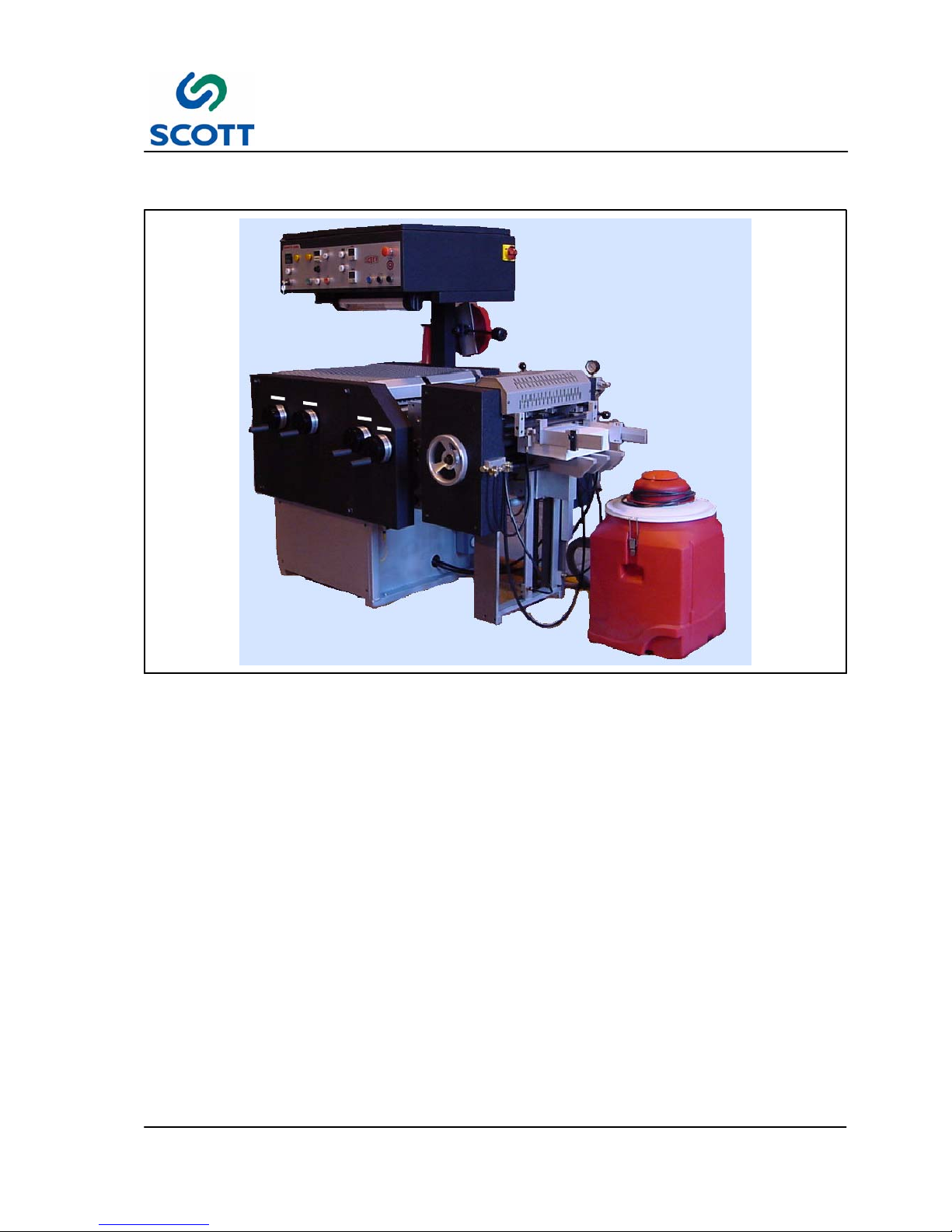
1.1 Introduction
Fig. 1-1. Scotty 5000t
The Scotty 5000t uses a vacuum feeder for accuracy with many stocks, a platen mylar applicator which
only heats the tab extension, tab cutting knives, and efficient receiving stacker for hands--off operation.
Tab sizes range from 1/2 inch to 5 inches (12.7 mm to 127 mm) by simply rotating the Tab Size handwheel.
The extra long tool steel knives quickly and easily cut a one inch (25.4 mm) tab in the first position on a 14
inch (355.6 mm) long sheet. As the tab widens, or the tab position moves toward the center of the sheet, the
sheet size capability increases accordingly.
Page 11

1 Introduction and Safety
1--4
F--9999--8 Build 8 Issue 1
1.1.1 Scotty 5000 Machine Specifications and Utility Requirements
Model Scotty 5000t
Speed
Up to 5000 tabs cut per hour
Up to 4200 tabs laminated and cut per hour
Sheet Size
355.6 mm x 342.9 mm (14” x 13--1/2”) maximum
127 mm x 111.1 mm (5” x 4--3/8”) minimum
Plastic Size
139.7 mm (5--1/2”) maximum
25.4 mm (1”) minimum
Tab Cut Size
127 mm (5”) maximum
12.7 mm (1/2”) minimum
Paper Load
Approximately 2000 sheets
Counter
1 -- 999999
Motor
1HorsePower
Electrical Requirements
30 Amps, 220VAC single phase, 50 or 60 Hz
Air Requirements
6 ScFm @ 80 P.S.I. (170LPM @ 5.3 bar)
Air Quality
Clean Dry Air filtered to 5 micron
Decibel Rating
94db
Dimensions
L--85” W--52” H--63” (L--2159mm W--1320.8mm H--1600.2mm)
Shipping Weight
2000 lbs (910 Kg)
Warranty
One year against defects in parts and workmanship
Note ! All Scott Machines require clean, dry air.
Optional air filters are available, contact your Scott representative for more details.
Page 12
1 Introduction and Safety
1--5
F--9999--8 Build 8 Issue 1
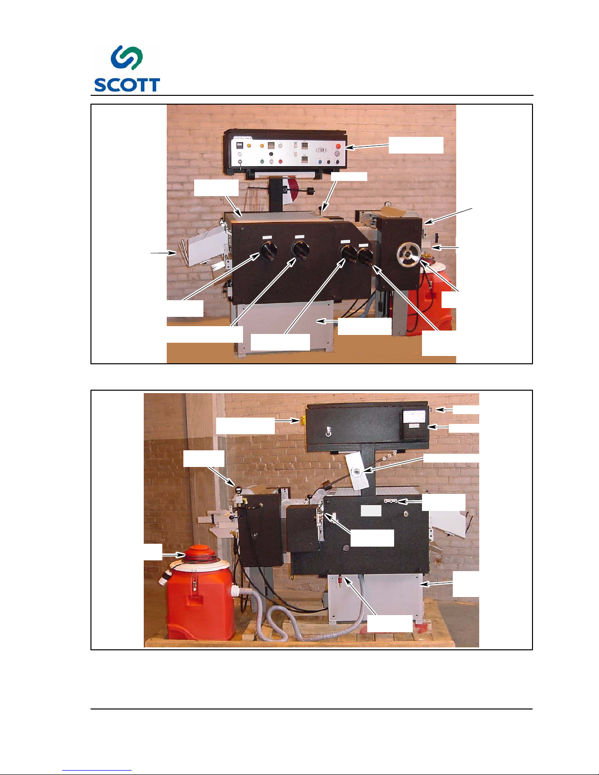
PAPER
SUPPORT
PAP ER
CATCHER
OPERATORS
PAN EL
PILE
FEEDER
TIP DIE
TAB
CUTTER
ELECTRICAL
BOX
PAPER LIFT
HANDWHEEL
PLASTIC
POSITION
HANDWHEEL
PLASTIC SIZE
HANDWHEEL
TAB POSITION
HANDWHEEL
TAB S IZE
HANDWHEEL
Fig. 1-2. Machine Front View
FILM
GUIDES
VACUUM
UNIT
TRANSFORMER
MAIN POWER
SWITCH
REEL HOLDER
PLASTIC
FEEDER
VACUUM
GAGE
DRIVE
MOTOR
AREA
AIR INLET
VALV E
TAB CUTTER OFF
Fig. 1-3. Machine Back View
Page 13

1 Introduction and Safety
1--6
F--9999--8 Build 8 Issue 1
1.2 General Safety Guidelines
Providing a safe working environment for operating your machine is the responsibility of the user. The
suggested precautions, material safety data and other suggestions that follow do not have preference over
the user’s own plant practices, regulations or safety committee recommendations.
Personal injury and equipment damage can be avoided by the continued adherence to the safety features
provided with this machine and in keeping with the necessary governmental requirements. The guarding
and interlocking safety switches have been installed on the machine for the operator’s safety. These items
should be maintained in good working order by the user.
It is assumed that the user’s safety department has established a safety program that is in keeping with a
complete analysis of industrial hazards. Before installing and operating or performing maintenance and
clean--up procedures on the machine, it is suggested that the safety program be reviewed to ensure that it
covers the possible hazards that might occur with the operation of this machine.
Due consideration must be given to those hazards which arise from the presence of electrical power, high
temperature, and cleaning materials used in the operational areas of the machine. Proper installation and
care of protective devices and over--pressure protective equipment should be considered an essential part of
any safety program.
Special lock--out features are to prevent the possibility of applying power to the equipment at any time when
maintenance work is in progress.
In general, personnel should be guided by all basic rules of safety associated with the equipment and the
process. It should be further understood that information contained in this manual does not relieve operating
and maintenance personnel of the responsibility of exercising normal good judgment in operating and care of
the machine and its attendant equipment.
Page 14
1 Introduction and Safety
1--7
F--9999--8 Build 8 Issue 1
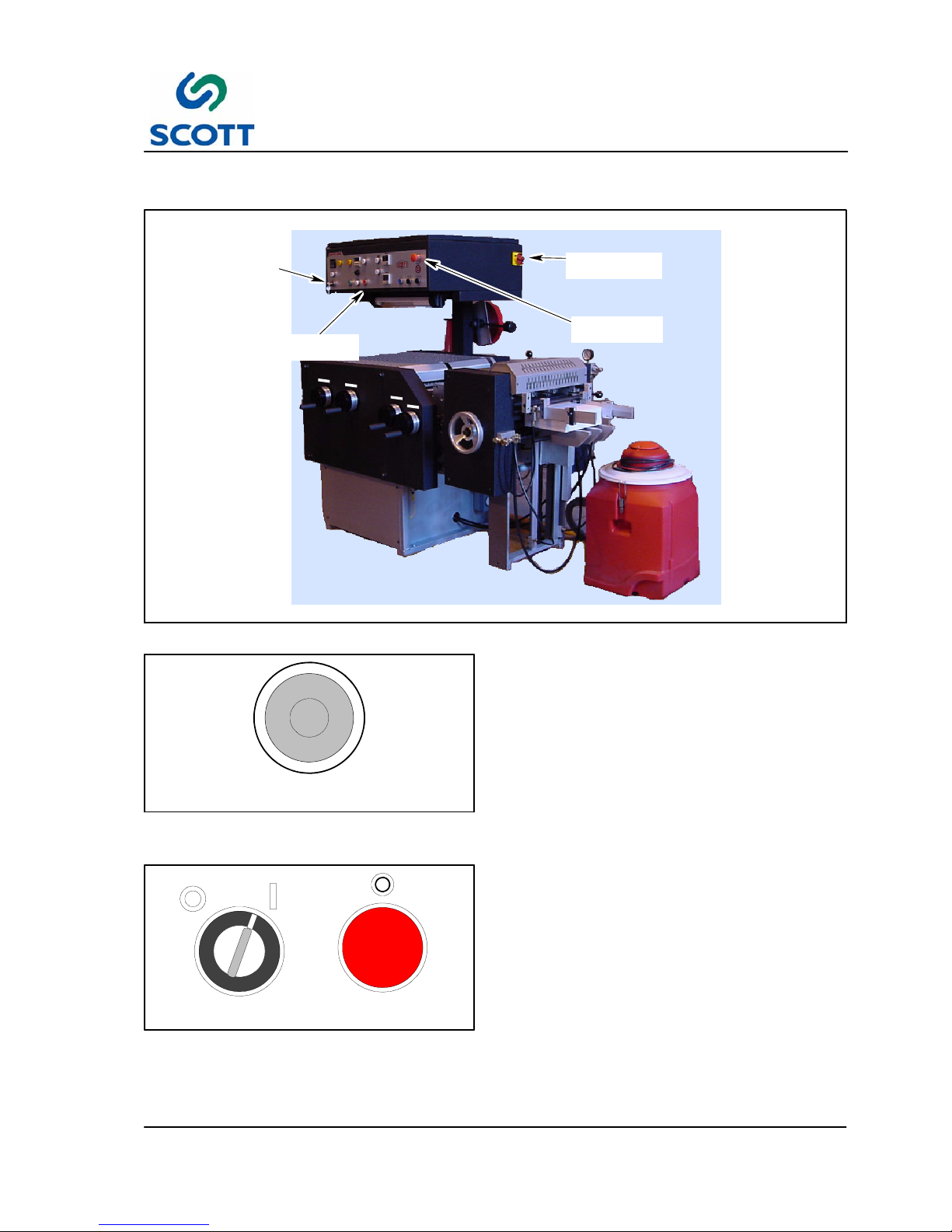
1.3 Safety Features
EMERGENCY
STOP
MAIN POWER
SWITCH
KEY SWITCH
STOP
PUSHBUTTON
Fig. 1-4. Safety Feature Locations
E--STOP
Fig. 1-5. Know Where Emergency Stop Button
is Located
These safety features are to be used in conjunction
with the installation, operation and maintenance
instructions contained in this manual.
1.3.1 Emergency Stop
Stops machine drive immediately. This pushbutton
must be manually pulled out to reset.
RUN
SAFE
STOP
Fig. 1-6. Know How to Stop Machine & Set Key
Switch to SAFE
1.3.2 Stop and Safe
The machine operator, clean--up and maintenance
personnel MUST be shown how to stop the
machine and place the KEY SWITCH on the
operator’s CONTROL PANEL in the SAFE mode
whenever machine is accessed or clean--up
operations are performed.
Page 15
1 Introduction and Safety
1--8
F--9999--8 Build 8 Issue 1
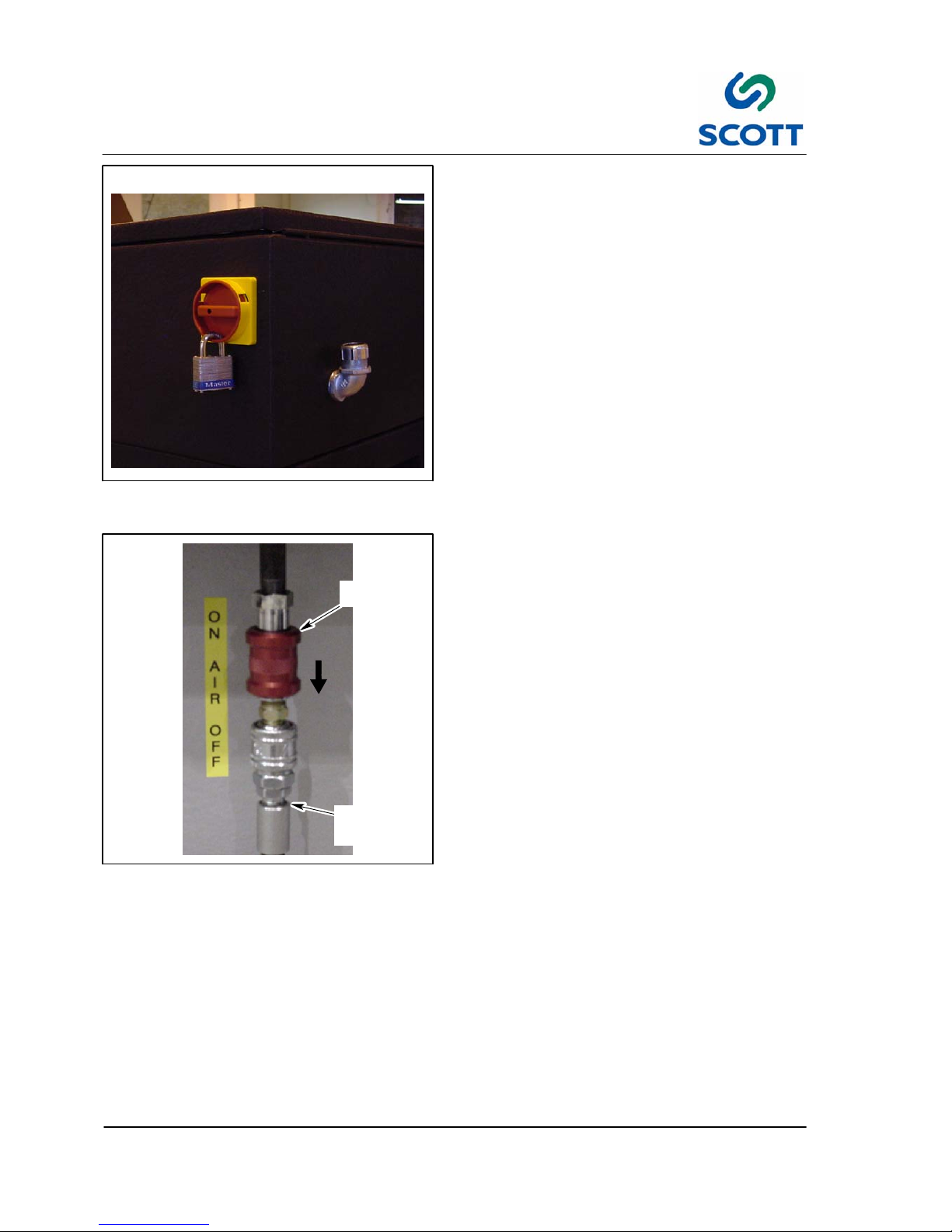
Fig. 1-7. Turn Machine Off Before Making
Adjustments
1.3.3 Main Power Switch
If machine is to be shut down for adjustments or
repairs, turn the power supply to the machine off.
VALV E
CONTROL
PLANT
AIR
SUPPLY
Fig. 1-8. Compressed Air Can Be Turned Off.
1.3.4 Compressed Air Valve
The compressed air line at the main AIR IN
features a ON/OFF valve for safety. The valve is
constructed to lockout down stream air pressure
when in the OFF position.
● The valve shuts off plant supplied compressed
air to the machine.
● Place the valve in the closed position when the
machine is not in use and prior to washing or
servicing the machine.
Page 16
1 Introduction and Safety
1--9
F--9999--8 Build 8 Issue 1
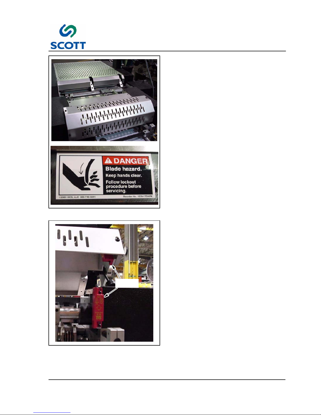
Fig. 1-9. Cover Warnings
1.3.5 Guards and Covers
All safety guards, protective screens and covers
MUST be in place and securely fastened before
operating the machine.
Observe Danger warnings. Use extra care around
moving cutting blades.
SAFETY
SWITCH
Fig. 1-10. Safety Devices
1.3.6 Safety Devices
The covers of the machine are connected to safety
devices for your protection.
Page 17
1 Introduction and Safety
1--10
F--9999--8 Build 8 Issue 1
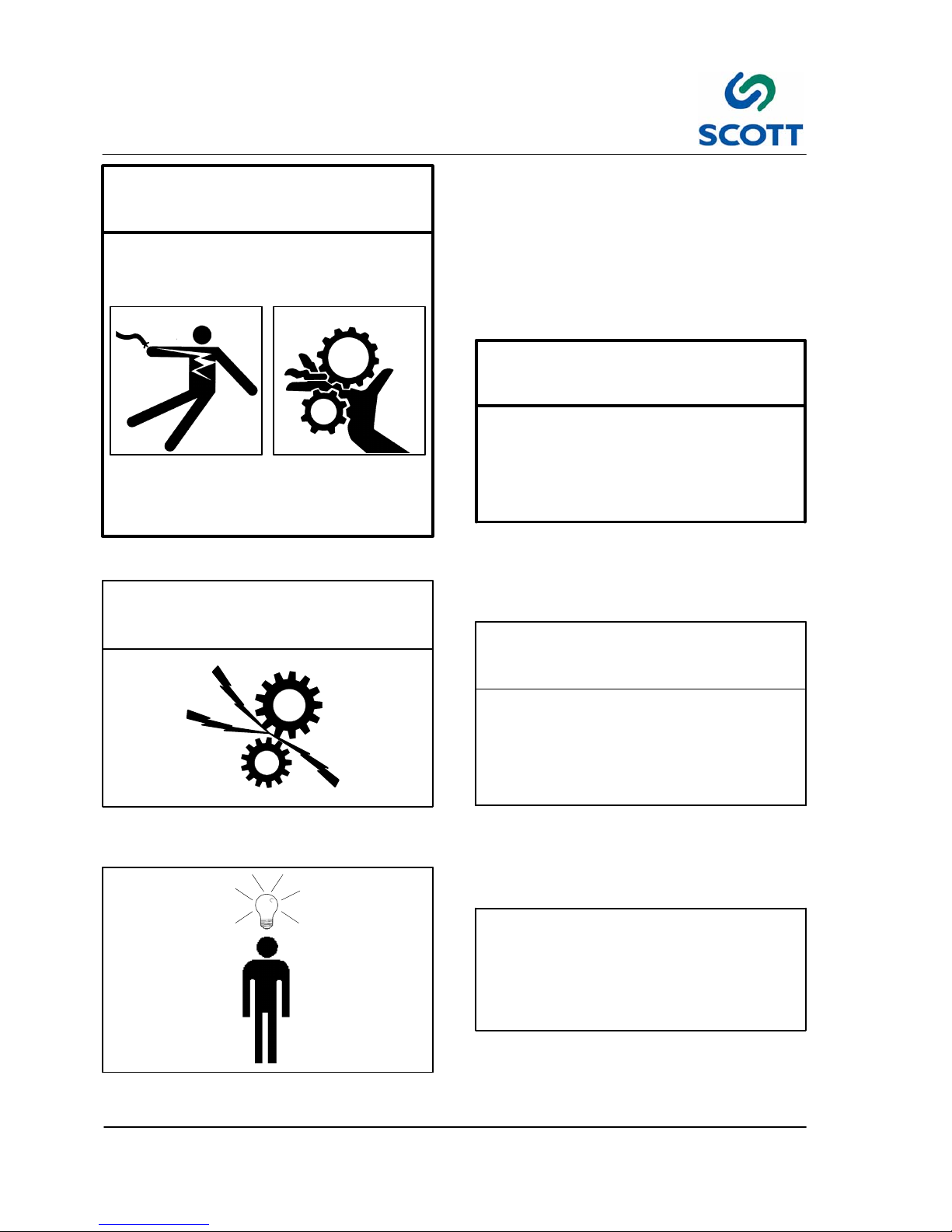
WARNING!
Fig. 1-11. Warnings Indicate Personal Danger
1.4 Warnings, Cautions & Notes
In order to emphasize certain areas in the interest
of personal safety and a properly operated and
maintained machine, you will encounter the words
WARNING, CAUTION, and NOTE.
1.4.1 Warnings
AN OPERATING PROCEDURE,
PRACTICE, ETC. WHICH IF NOT
CORRECTLY FOLLOWED, COULD
RESULT IN PERSONAL INJURY OR
LOSS OF LIFE.
WARNING!
CAUTION!
Fig. 1-12. Cautions Indicate Potential Damage
to Equipment
1.4.2 Cautions
AN OPERATING PROCEDURE,
PRACTICE, ETC. WHICH, IF NOT
STRICTLY OBSERVED, COULD RESULT
IN DAMAGE TO OR DESTRUCTION OF
EQUIPMENT.
CAUTION!
Note !
Fig. 1-13. Notes Indicate Essential Information
1.4.3 Notes
An Operating Procedure, Condition,
etc. Which is Essential To Highlight.
Note !
Page 18

1 Introduction and Safety
1--11
F--9999--8 Build 8 Issue 1
Fig. 1-14. Heat Hazard
1.5 Warnings
1.5.1 Heat Hazards
Forexample,thereisHOTSURFACEsignontop
of the Plastic Press assembly. Look for warning
signs throughout the machine. They are there to
alert you to hazards.
Fig. 1-15. Electrical Shock Hazard
1.5.2 Electrical Shock Hazards
Look for warning signs on electrical cabinets and
circuit breaker boxes. They are there to alert you
to hazards of electrical shock.
Page 19
1 Introduction and Safety
1--12
F--9999--8 Build 8 Issue 1
VALV E
CONTROL
PLANT
AIR
SUPPLY
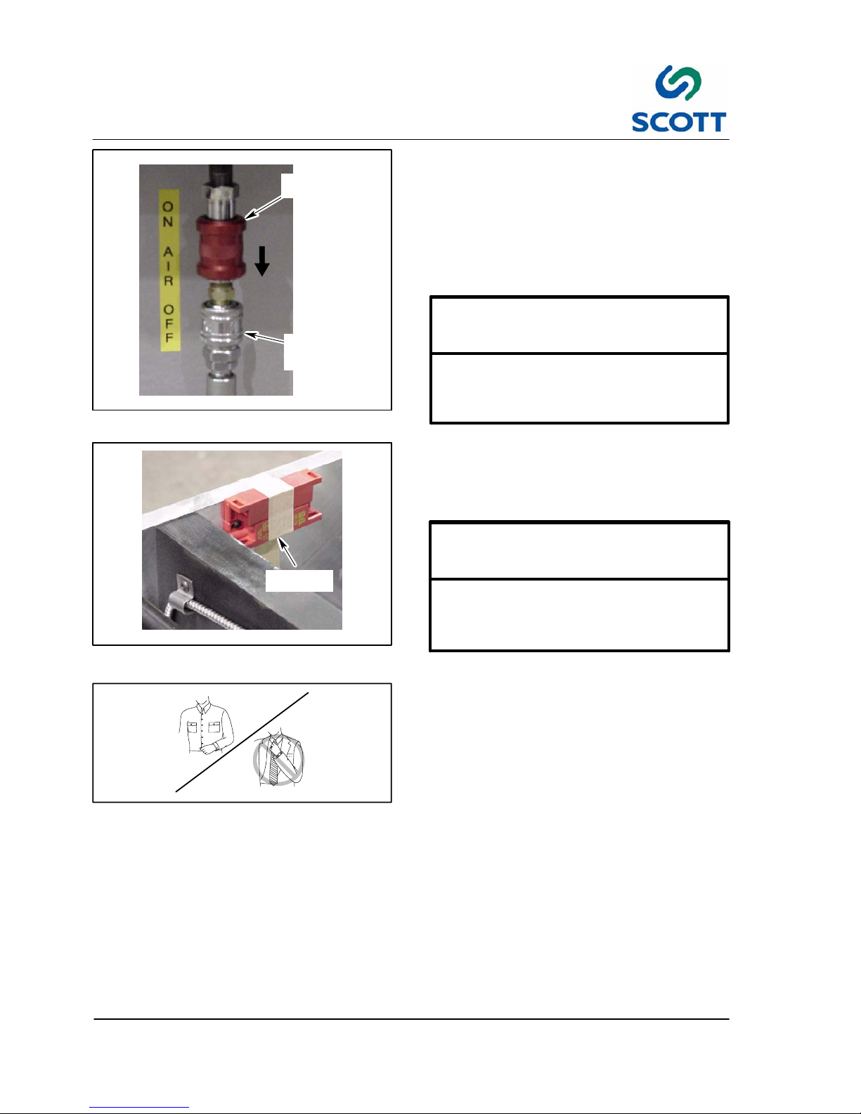
Fig. 1-16. Compressed Air Valve.
1.6 Safety Procedures
1.6.1 Compressed Air Valve
Assemblies which are air actuated may have
pressure remaining in the air lines. Turn OFF
valve before working on pneumatic circuits to
release air trapped in the system.
DRAIN LINES OF COMPRESSED AIR TO
PREVENT ACCIDENTAL ACTIVATION OF
AIR DRIVEN ASSEMBLIES.
WARNING!
SAFETY
SWITCH
Fig. 1-17. Do Not Disable Safety Devices
1.6.2 Safety Devices
Tampering with safety mechanisms in order to
disable them should not be tolerated.
IT IS EXTREMELY DANGEROUS TO ACCESS
MACHINE WHEN IT IS OPERATING OR
CAPABLE O F OPERATING.
WARNING!
Fig. 1-18. Wear Proper Clothing
1.6.3 Appropriate Dress
Personnel working in the machine operation area
must remove jewelry and neckties. Personnel
must wear clothing appropriate for the work area.
Page 20
1 Introduction and Safety
1--13
F--9999--8 Build 8 Issue 1
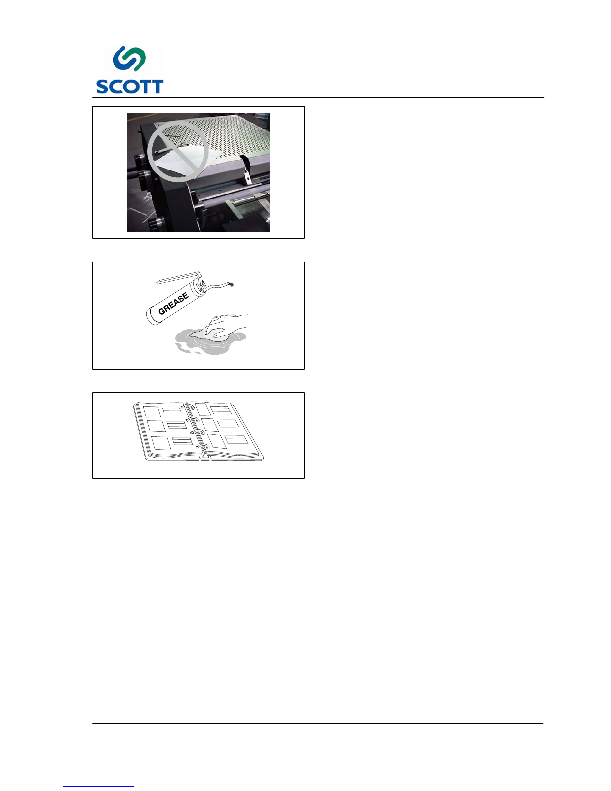
Fig. 1-19. Keep Work Area Clean and Neat
1.6.4 Keep Area Clean
Loose materials, tools and equipment, not
essential to the operation of the machine, must be
removed from the machine work area.
Fig. 1-20. Clean Up Oil and Grease Spills
1.6.5 Grease and Oil
Clean up all oil and grease spills around the
machine work area.
Fig. 1-21. Read Manuals First
1.6.6 Manual Usage
Read and understand the instructions in the
manual before operating, adjusting or servicing
machine.
Page 21

2 Installation
2--1
F--9999--8 Build 8 Issue 1
2 INSTALLATION
Page 22

2 Installation
2--2
F--9999--8 Build 8 Issue 1
Page 23

2 Installation
2--3
F--9999--8 Build 8 Issue 1
2.1 Installation Requirements
Fig. 2-1. Scotty 5000
All procedures in this section provide advance planning and site preparation data for installation of the Scotty
5000. Environmental requirements, unpacking instructions, and electrical and physical specifications are
included. This information should be used as a reference during the development of site preparation plans
before you install your machine.
If any questions arise while performing any of the following procedures, contact
Training is available from Scott Office Systems at / eight hour day, plus all travel expenses.
Note ! A forklift is required to lift the machine off the shipping skid and place it on the floor.
Page 24
2 Installation
2--4
F--9999--8 Build 8 Issue 1
2.1.1 Pre-Installation Requirements
The environmental requirements of the Scotty 5000 must be considered well in advance of the actual
installation. Providing a well suited operating environment will help ensure a trouble free installation process.
Consideration should be given to the following items:
● Power, location and rating of outlets
● Floor strength
● Level floor
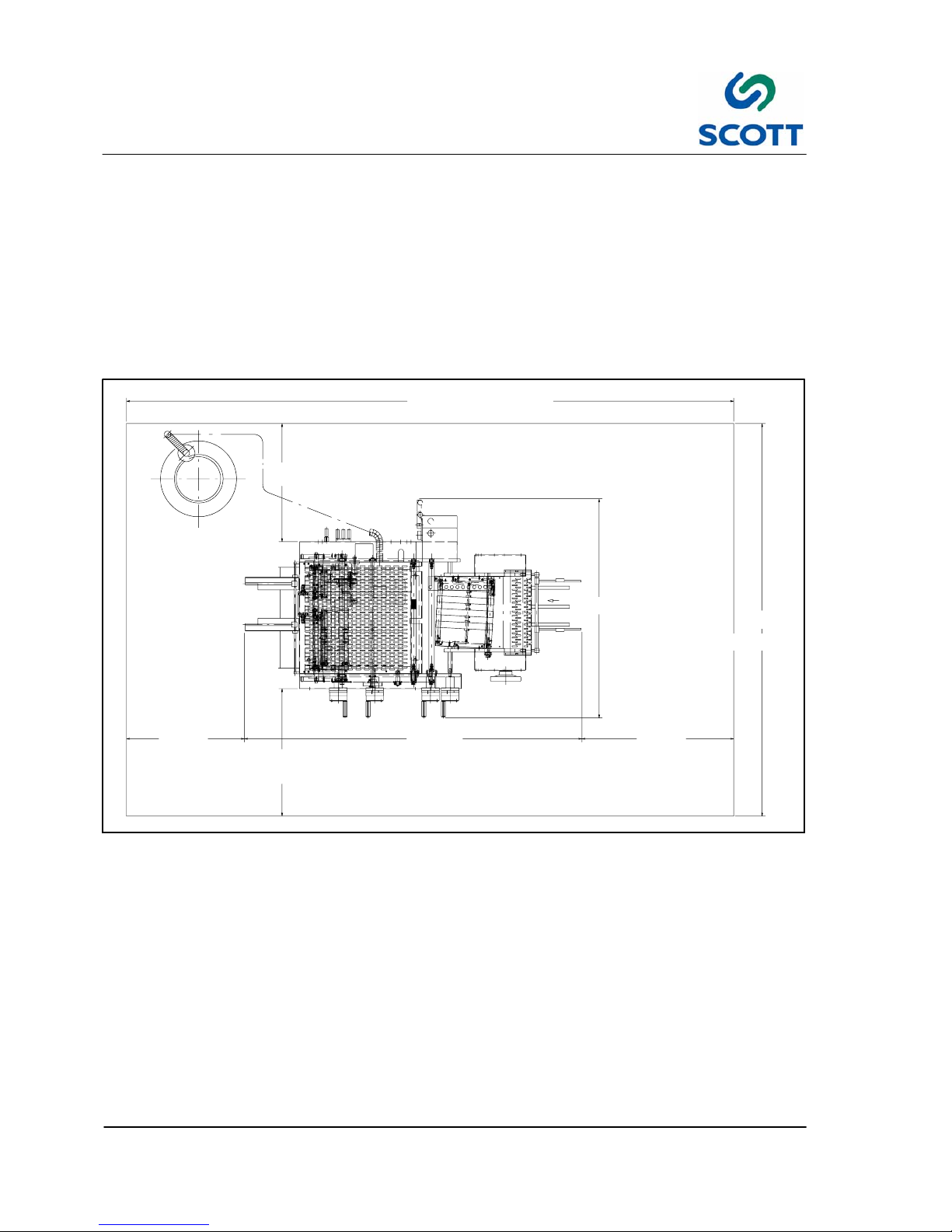
● Adequate space must be provided around all four sides of the machine to permit normal operation and
maintenance procedures. The figure shows the minimum space required.
12’--0” (3657mm)
2’--4”
3’--0”6’--8”
4’--4”
2’--4” (711mm)
2’--6”
7’--9”
(711mm)
(2032mm)
(914mm)
(762mm)
(2362mm)
Fig. 2-2. Space Requirements
● Space should be allocated near the feeder for a small table that can be used for jogging stock, small jobs,
samples, etc.
● Provide plenty of space In front of the machine so large jobs can be easily moved in and out with skids or
carts.
Page 25
2 Installation
2--5
F--9999--8 Build 8 Issue 1
2.1.2 Uncrating & Placement
The machine will arrive crated. Inspect the external condition of the crate for visible signs of damage before
opening. If damage is noticeable, notify the carrier or Scott before proceeding with the installation.
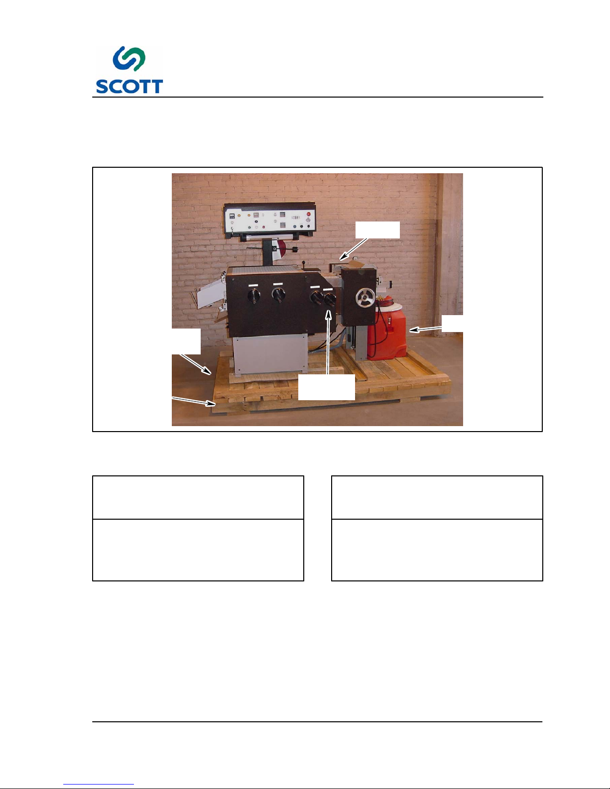
VACUUM
UNIT
PLASTIC
POSITION
HANDWHEEL
SHIPPING
SKID
MAIN
MACHINE
RAISE FROM
THIS SIDE
OF SKID
Fig. 2-3. Scotty 5000 on Shipping Skid
Step: 1. Remove shrink wrap enclosing the machine.
REMOVE SUPPORT BOARD BEFORE
PROCEEDING FUTHER. CARE MUST
BE TAKEN WHEN MOVING THE
MACHINE SO AS NOT TO DAMAGE IT.
CAUTION!
EXTREME CAUTION MUST BE
EXERCISED WHEN MOVING MACHINE
TO INSTALLATION LOCATION TO
PREVENT DAMAGE.
CAUTION!
Step: 2. With fork lift, place shipping skid near designated floor area of operation.
Step: 3. Remove vacuum unit from skid.
Step: 4. Remove four lag screws holding machine to shipping skid.
Step: 5. Raise main machine with fork lift, remove shipping skid assembly from under machine.
Step: 6. Lower main machine to floor.
Page 26
2 Installation
2--6
F--9999--8 Build 8 Issue 1
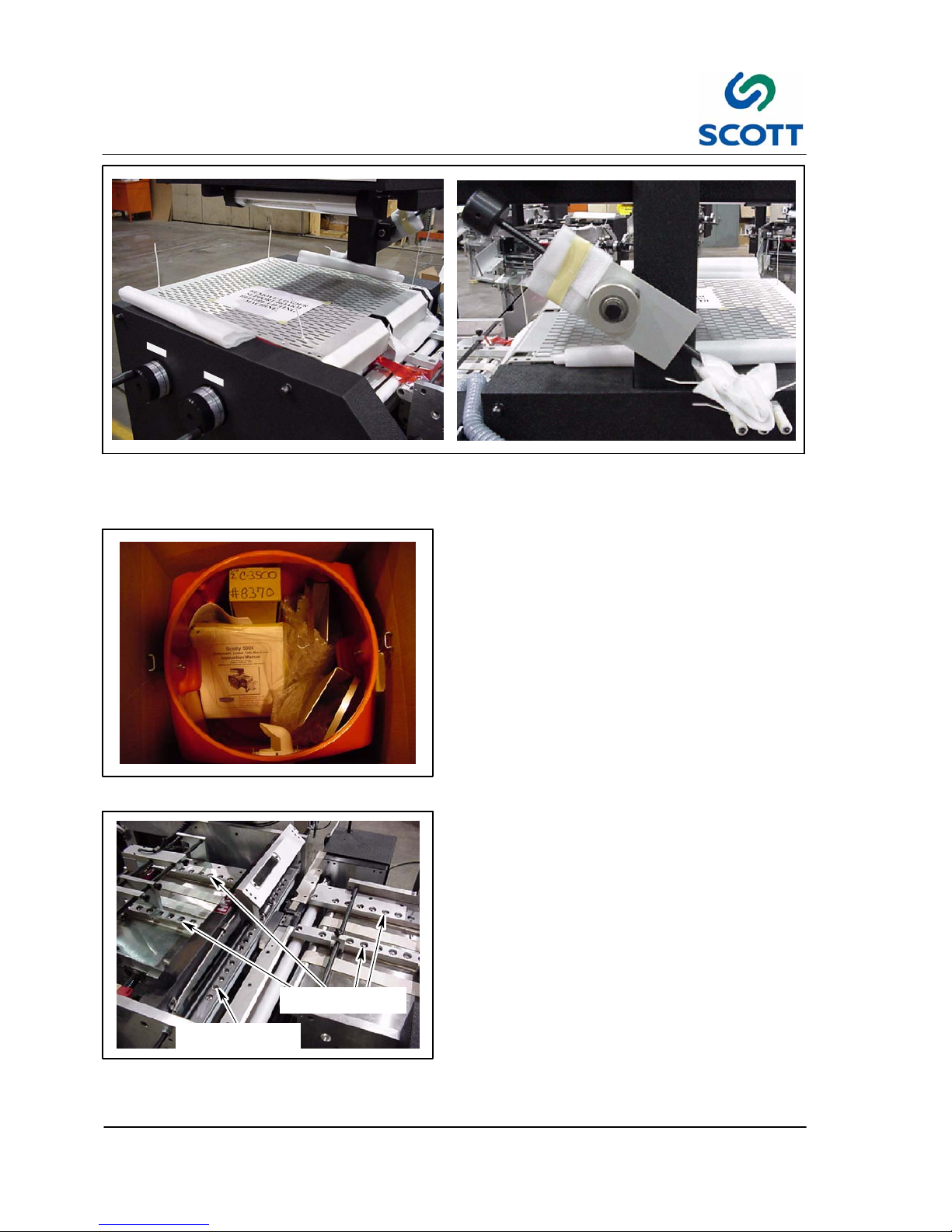
Fig. 2-4. Remove Foam and Tie Wraps
Step: 7. Remove the foam and tie wraps that were protecting the machine during shipping.
Fig. 2-5. Remove Parts from Vacuum Canister
Step: 8. Once the machine is in place, open the
vacuum canister and remove packaged
parts.
LARGE BALL
BEARING POCKETS
SMALL BALL
BEARING POCKETS
Fig. 2-6. Install Ball Bearings
Step: 9. Install ball bearings in the correct
pockets.
Page 27
2 Installation
2--7
F--9999--8 Build 8 Issue 1
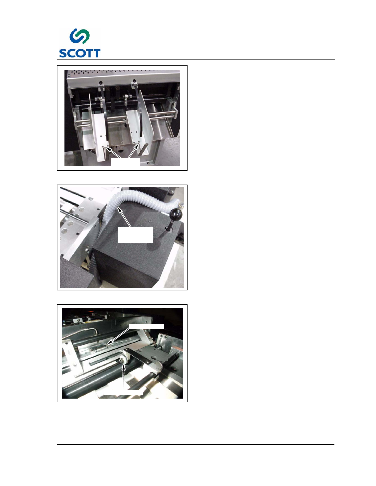
PAPER
CATCHER
Fig. 2-7. Install Paper Catcher
Step: 10.Install paper catcher parts.
VACUUM
CANISTER
HOSE
Fig. 2-8. Release Hose
Step: 11.Crank the Plastic Position handwheel to
release the vacuum canister hose. (See
Fig. 2-3. for Plastic Position Handwheel
location)
DRIVE ROLLER
HUB ROLLER
Fig. 2-9. Install Drive Roller
Step: 12.Install Drive Roller. Align drive roller to
the center of the hub roller on platen unit.
This is used to assist short sheets into
the platen unit.
Page 28
2 Installation
2--8
F--9999--8 Build 8 Issue 1
VACUUM
VALV E
Fig. 2-10. Install Vacuum Valve
Step: 13.Install vacuum adjustment valve.
THREADED
LEVELING
HOLES (2 FRONT)
LEVELING SCREWS
Fig. 2-11. Leveling Rod Installation
Step: 14.The machine must be on a level surface. However, If machine is to be placed on an abnormally
uneven floor, machine may be leveled in the following manner:
● Install 3/4 in.--#10 threaded rods through four threaded holes In machine weldment. (See Fig. 2-11. )
● Threaded rods can then be used to level machine. Use appropriately sized jam nuts to maintain level
position when attained.
Page 29
2 Installation
2--9
F--9999--8 Build 8 Issue 1
DANGER: ELECTRICAL CONNECTIONS
MUST BE MADE BY A QUALIFIED
ELECTRICIAN FAMILIAR WITH
APPLICABLE ELECTRICAL CODES
AND REGULATIONS. ELECTRICAL
CONNECTIONS MUST THEN BE MADE
ONLY AFTER REVIEWING AND
UNDERSTANDING THE ELECTRICAL
SCHEMATICS SUPPLIED WITH
MACHINE AND SAFETY SECTION OF
THIS MANUAL, FAILURE TO EXERCISE
NECESSARY SAFETY PRECAUTIONS
CAN RESULT IN SERIOUS BODILY
INJURY OR DEATH.
WARNING!
2.2 Utility Connections
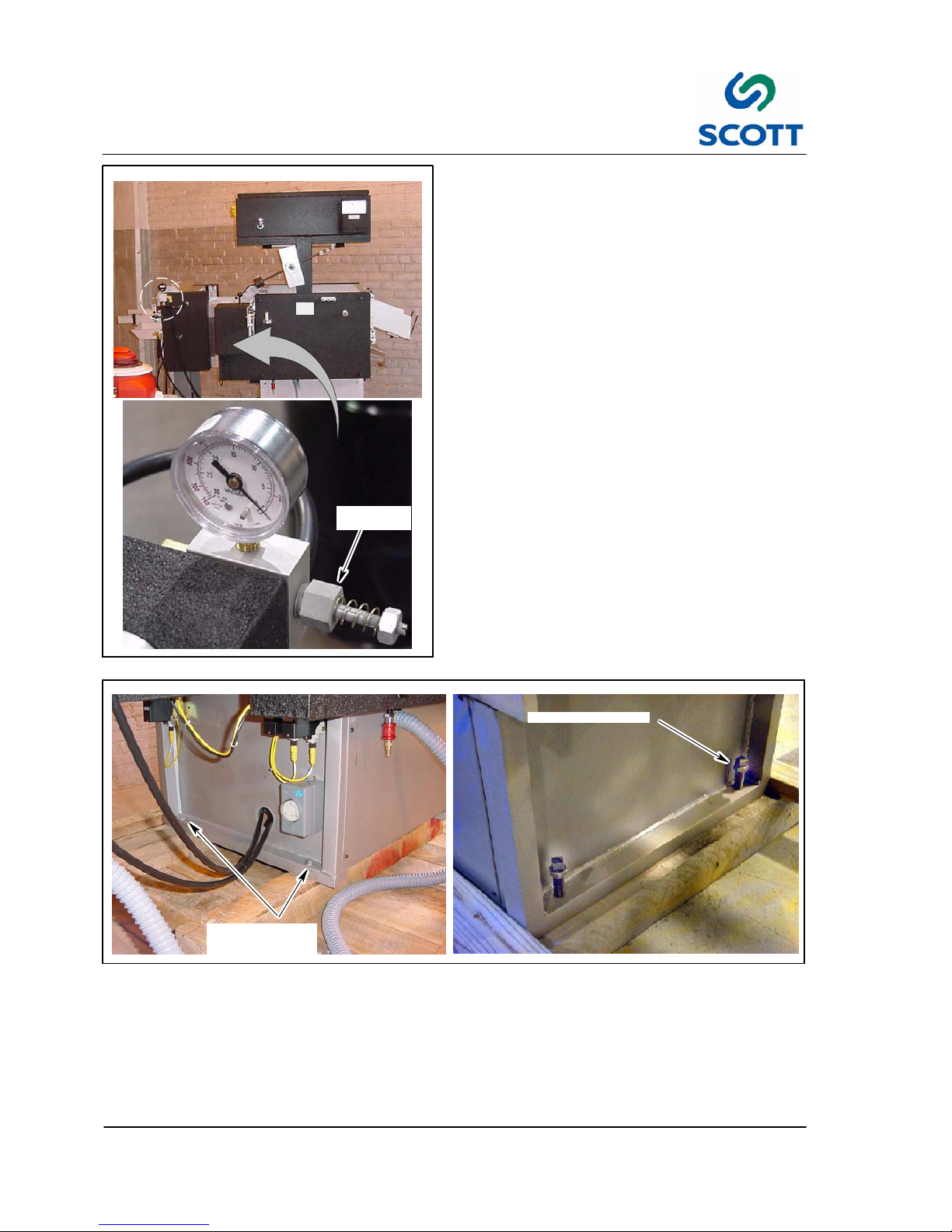
2.2.1 Electrical Connections
1. The machine requires No. 10, 3 wire cable
including ground for 220 volt, single phase
electrical power.
Note ! Electrical cables going to machine
should be routed overhead and be of
sufficient height to allow personnel to
travel around entire machine without
interference. The figure below shows
recommended installation
configuration.
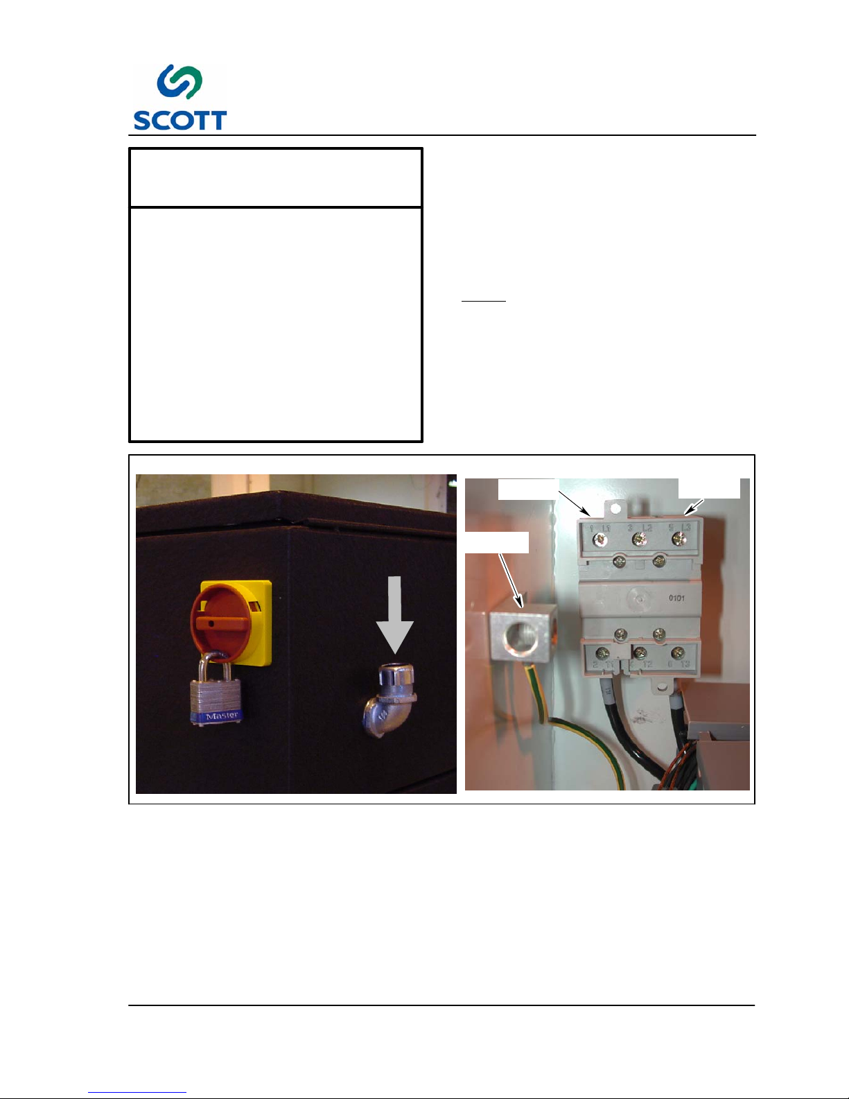
GROUND
TERMINAL
1L1
TERMINAL
5L3
TERMINAL
Fig. 2-12. Installation Wiring Route
2. Route main power electrical cable through the conduit opening in the back of the control cabinet.
3. Connect two “hot” leads onto terminals 1L1 and 5L3 on main power relay. Connect neutral lead to
ground terminal.
Page 30
2 Installation
2--10
F--9999--8 Build 8 Issue 1
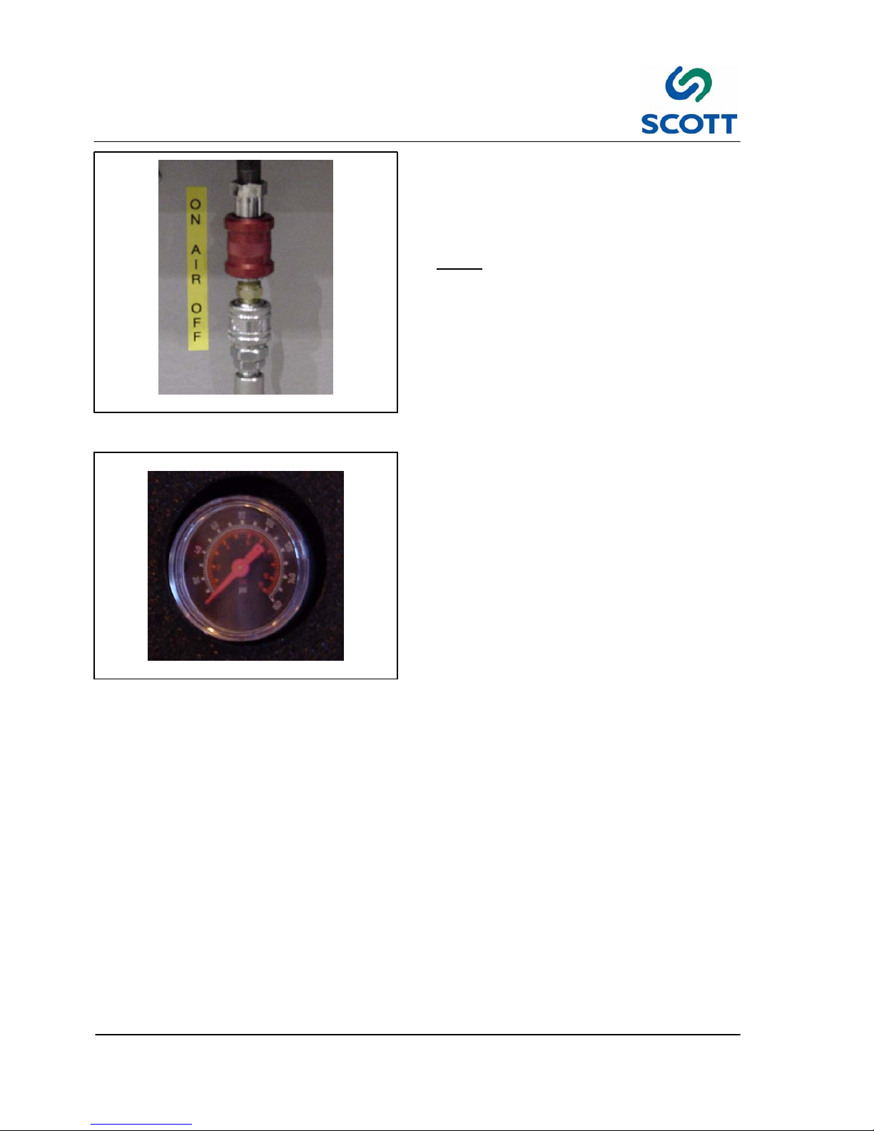
Fig. 2-13. Connect Air Supply
2.2.2 Connect Air Supply
1. Supply a 1/4 NPT air line with 6 ScFm @
80psi (170LPM @ 5.3bar)to the air shut off
valve located at the back of the machine.
Note ! The compressed air line at the main
AIR IN features a ON/OFF valve for
safety. Place the valve in the closed
position when connecting the
machine to the plant air supply.
Fig. 2-14. Air Supply Gage
Set the Regulator to 60psi (4.0bar).
Page 31

3 Operation
3--1
F--9999--8 Build 8 Issue 1
3 OPERATION
Page 32

3 Operation
3--2
F--9999--8 Build 8 Issue 1
Page 33

3 Operation
3--3
F--9999--8 Build 8 Issue 1
3.1 General Information
3.1.1 Before Operating the Machine
AVOID SERIOUS INJURY OR EQUIPMENT
DAMAGE. RESTRICT OPERATION OF THIS
MACHINE TO TRAINED, QUALIFIED
PERSONNEL ONLY.
WARNING!
EACH OPERATOR SHOULD KNOW THE
LOCATION AND FUNCTION OF ALL
MACHINE STOPPING CONTROLS.
REVIEW MANUAL FOR EMERGENCY
STOP BUTTON LOCATION.
WARNING!
Do not attempt to operate the machine before reading and understanding the manual. Pay close attention to
all WARNINGS, CAUTIONS and NOTES. Failure to do so may cause serious injury and extensive machine
damage.
Read through the inspection and pre--start procedures before starting the machine. Make these checks part
of your routine to insure efficiency and quality during the production run.
Page 34

3 Operation
3--4
F--9999--8 Build 8 Issue 1
3.2 Operating Controls and Indicators Descriptions
3.2.1 Operator’s Control Panel Layout
UPPER
HEAT
LOWER
HEAT
STOP
PAP ER
FEED
START
RUN/SAFE
RESET
FEED
DELAY
HEATER
SEAL
TIME
PLASTIC
FEED
COUNT
REACHED
EMERGENCY
STOP
OUT OF
PLASTIC
COUNTER
ON/OFF
COUNTER
PLATEN
CLOSE
PLASTIC
ADVANCE
DRIVE
SPEED
TAB CUTTER OFF (SIDE OF MACHINE)
Fig. 3-1. Control Panel
E--STOP
Fig. 3-2. Emergency Stop Pushbutton
3.2.2 Machine Stopping Device
3.2.2.1 EMERGENCY STOP -- Red Pushbutton
Stops the machine drive immediately. The
Emergency Stop Button is on the front of the
machine. After a stop, the button must be
manually pulled out and the Reset button pushed
before cycling can resume.
Page 35

3 Operation
3--5
F--9999--8 Build 8 Issue 1
3.2.3 Main Operator’s Panel Control Descriptions
The following is a list of each control on the operator’s panel and a description of the functions performed at
each setting.
TAB CUTTER
OFF
Fig. 3-3. Tab Cutter Off
3.2.3.1 TAB CUTTER OFF -- Red Illuminated
Pushbutton
The Tab Cutter Off Button located on the left side
of the operator’s box and is used to disable the
cutting knives when running production that
involves laminating tabs only (not tab cutting).
OFF-- When pushed this button disables the tab
cutting knives so that sheets are not cut.
ON -- When pushed, knives are raised into position
so that tabs will be cut.
COUNTER
Fig. 3-4. Counter On/Off -- Illuminated
Pushbutton
3.2.3.2 COUNTER ON / OFF -White Illuminated Pushbutton
When the counter button is pushed, the button
illuminates indicating that the counter is on.
This will allow the operator to off the counter to run
make overs without losing the current count.
COUNT
REACHED
Fig. 3-5. Count Reached Lamp
3.2.3.3 COUNTER REACHED -Amber Indicator Lamp
This lamp will illuminate when the machine has
produced the amount predetermined by the
counter. Once the count has been reached, the
paper feed vacuum pump will shut off so that paper
feed will stop. Also, if plastic is being applied to
the paper stock, the plastic chip removal vacuum
will shut off. Both units will resume operation once
the counter has been reset.
Page 36

3 Operation
3--6
F--9999--8 Build 8 Issue 1
RUN
SAFE
Fig. 3-6. Run/Safe Key Switch
3.2.3.4 SAFE / RUN -- Key Switch
RUN -- The machine drive cycles continuously.
This is the normal switch position for production.
SAFE -- No machine cycle is possible.
If conditions are safe, pushing RESET will allow
the machine to operate.
OUT OF
PLASTIC
Fig. 3-7. Out of Plastic Lamp
3.2.3.5 OUT OF PLASTIC -- LAMP
Lamp will illuminate when upon pushing the Plastic
Feed button, the proximity switch on the plastic
feed does not sense plastic at the feeder
discharge. The plastic chip removal vacuum and
the paper feed vacuum pump will also be disabled
until the plastic spool is refilled.
START
Fig. 3-8. Start Pushbutton
3.2.3.6 START -- Green Pushbutton
Turns on main drive motor to begin machine
cycling.
This means:
● The safety switches indicate all the guards are
in place.
● The EMERGENCY STOP buttons are reset.
● The RESET button is pushed.
● The pushbutton turns on the main drive motor
for continuous machine cycling with the KEY
switch in RUN position.
PAPER
FEED
Fig. 3-9. Paper Feed Pushbutton
3.2.3.7 PAPER FEED -- White Illuminated
Pushbutton
Starts the vacuum pump for the pile feeder vacuum
nozzles.
Page 37

3 Operation
3--7
F--9999--8 Build 8 Issue 1
STOP
Fig. 3-10. Stop Drive Pushbutton
3.2.3.8 STOP -- Red Pushbutton
The pushbutton stops the machine drive. This is a
“soft” stop and is intended for planned stops, not
emergencies.
FEED
DELAY
Fig. 3-11. Feed Delay -- Illuminated Pushbutton
3.2.3.9 FEED DELAY -- White Illuminated
Pushbutton
Shuts off the vacuum to the paper pick--up vacuum
nozzles to prevent a new sheet from being fed into
the machine until the preceding sheet has cleared
the press assembly. The amount of time that the
paper is in the press will depend on the time that is
preset in the Seal Time unit.
HEATER
Fig. 3-12. Heaters Illuminated Pushbutton
3.2.3.10 HEATERS ON / OFF --
ON -- When pushed, the button illuminates,
indicating upper and lower heaters are turned ON.
OFF -- When pushed again, the heaters are turned
OFF.
Approximate warm up time for heaters is between
10--15 minutes.
NOTE: See additional information under Heater
Temperature Controller write--up.
PLASTIC
FEED
Fig. 3-13. Plastic Feed Pushbutton
3.2.3.11 PLASTIC FEED -- White Illuminated
Pushbutton
Turns on the chip removal vacuum and allows
plastic to enter the Tip Die, if the reel is threaded
onto the machine. The plastic chip removal
vacuum operates only when Plastic Feed is on,
machine is in Run mode and machine is running.
Page 38

3 Operation
3--8
F--9999--8 Build 8 Issue 1
RESET
Fig. 3-14. Reset Pushbutton
3.2.3.12 RESET -- Blue Pushbutton
Resets machine, and verifies it is safe to run after
an emergency stop.
Press this button when changing the Run/Safe
switch from Safe position to Run.
PLATEN
CLOSE
Fig. 3-15. Platen Close Pushbutton
3.2.3.13 PLATEN CLOSE -- Black Pushbutton
Activates plastic press air cylinder for cleaning
purposes.
PLASTIC
ADVANCE
Fig. 3-16. Plastic Advance Pushbutton
3.2.3.14 PLASTIC ADVANCE -- Black
Pushbutton
It brings plastic into the Tip Die when the machine
is in Run position. It is used when loading a new
reel of film and must be held in.
Page 39

3 Operation
3--9
F--9999--8 Build 8 Issue 1
DRIVE SPEED
Fig. 3-17. Main Drive Feed
3.2.3.15 SPEED -- Adjustment Control
Adjusts main drive motor speed. The dial is turned
clockwise to increase, and counterclockwise to
decrease the machine drive speed.
Note ! Drive speeds too low or too high will
cause improper machine operation.
COUNT RESET
COUNT SET
NUMBER
OF
SHEETS
RAN
COUNT SET
Fig. 3-18. Feeder Counter
3.2.3.16 FEEDER COUNTER
Activating the Feeder Counter, allows operator to
specify an exact number of sheets to be run. The
feeder shuts off after the requirement has been
met.
The counter only counts when the machine is in
RUN mode and the Counter button is ON. The
digital counter counts forwards to the number
specified, then shuts feeder and vacuum OFF
when that number is reached.
● Do not change setting while counter is running.
Page 40

3 Operation
3--10
F--9999--8 Build 8 Issue 1
Fig. 3-19. Heater Temperature Control
3.2.3.17 Heater Temperature Control
Controls upper and lower platen temperatures by
cycling power to the heaters. The setpoint
temperature is adjusted by using the buttons below
the indicator display.
Note ! The heat controllers will automatically
turn off if the machine is not run for
two hours. The heat button will stay
illuminated but the controllers will go
dark and the platen will loose heat.
To restart the machine:
Press the start
button while the heater button is still
on and the machine will start to heat
again.
1. PV:Processing value indicator(Red color)
2. SV:Setting value indicator(Green color)
3. ARROWS(3): Key shifting the display.
4. Information for operation mode.
5. AT Key: The mode key to execute Auto tuning
function.
6. MD Key: The mode key to change the items to
be set, such as alarm value, etc.
7. EV2: EVENT2 Output signal lamp. (Not Used)
8. EV1: EVENT1 Output signal lamp. (Not Used)
9. OUT: Output signal lamp.
10.AT: The signal lamp flickers while Auto tuning is
being executed.
11. SV2: Signal lamp for SV2 operation. (Not Used)
Page 41

3 Operation
3--11
F--9999--8 Build 8 Issue 1
SEAL TIME
Fig. 3-20. Seal Timer
3.2.3.18 Seal Timer
Operate the pushbuttons to select the desired
settings.
1. Display Window
2. Operator Pushbuttons
3. Time Unit Display Window
● Set on 0.1s always.
4. Rated Time Display Window
● Do not set all three digits to zero.
5. Operation Mode Display Window
● Always on “E”
Page 42

3 Operation
3--12
F--9999--8 Build 8 Issue 1
3.2.4 Scotty 5000 with Telemecanique PLC Control
The Scotty 5000 incorporates two Telemecanique TSX07 Programmable Logic Controllers. Each controller
has a series of LEDs indicating the on/off status of its inputs and outputs. Separate LEDs also verify
communication between controllers. Check Electrical Sheets 8 and 8A for a listing of the devices that are
attached to the controller and to which location (input/output), the device is attached.
When a device is active, the green LED is lit. The yellow com LED should always be lit. The second smaller
PLC will have a blinking red LED in the error position which is normal. The larger primary PLC error lamp
should not be lit.
Page 43

3 Operation
3--13
F--9999--8 Build 8 Issue 1
3.3 Preliminary Inspection and Start-Up Procedure
VALV E
CONTROL
Fig. 3-21. Air Valve Control
3.3.1 Preliminary Set-Up
Step: 1. SlidethevalvecontroluptotheON
position.
MAIN
POWER
SWITCH
Fig. 3-22. Circuit Breaker Switch (ON)
Step: 2. Main Power Switch ON.
HEATER
Fig. 3-23. Warm Up Heater
To laminate plastic to paper:
Step: 3. Press HEATER pushbutton.
Step: 4. Set temperature controllers to
220--230_F as a starting point.
Note ! Starting Heaters now will allow
heaters to reach operating
temperature while the rest of the
machine is being set up.
Page 44

3 Operation
3--14
F--9999--8 Build 8 Issue 1
ADJUSTMENT KNOB
Fig. 3-24. Loosen Guide Roller Adjustment
Knob
Reel Holder
Step: 1. Loosen adjustment knob on the bottom
roller guide.
ROLLER
ROLLER GUIDES
3 FILM THICKNESS
Fig. 3-25. Set Gap Between Plastic Feed Roller
Guides to 3 Film Thickness
Step: 2. Set the gap between the plastic feed
roller guides to 3 film thickness by
moving the lower roller guide.
Step: 3. Tighten the adjustment knob.
Page 45

3 Operation
3--15
F--9999--8 Build 8 Issue 1
FILM
REEL
FILM
SPOOL
FILM
GUIDES
Fig. 3-26. Loading the Film
Step: 4. Load film reel on the reel holder.
Step: 5. Thread film through the film guides as
shown.
Fig. 3-27. Refer to Decal for Film Loading
Page 46

3 Operation
3--16
F--9999--8 Build 8 Issue 1
PLASTIC
FEEDER
Fig. 3-28. Hand Feed Film into Machine
Step: 6. Hand feed film into the plastic feed
mechanism.
RUN
SAFE
Fig. 3-29. Key Switch
Step: 7. Turn key switch to RUN
RESET
Fig. 3-30. Reset Pushbutton
Step: 8. Press RESET pushbutton.
Page 47

3 Operation
3--17
F--9999--8 Build 8 Issue 1
DRIVE SPEED
Fig. 3-31. Adjust Drive Speed
Step: 9. Adjust drive speed to 7.
START
Fig. 3-32. Start Pushbutton
Step: 10.Press START pushbutton.
PLASTIC
ADVANCE
Fig. 3-33. Plastic Advance Pushbutton
Step: 11.Press and hold PLASTIC ADVANCE
pushbutton till plastic enters the Tip Die.
STOP
Fig. 3-34. Stop Drive Pushbutton
Step: 12.Press STOP pushbutton.
Page 48

3 Operation
3--18
F--9999--8 Build 8 Issue 1
1/32”
FILM
TIP DIE
FILM STOP
FILM STOP
FILM STOP
ADJUSTMENT SCREW
WINDOW ASSEMBLY
Fig. 3-35. Remove Film Scrap from Tip Die Area
Step: 13.Lift the window assembly to expose the
Tip Die.
Step: 14.Loosen the film stop adjustment screw.
Step: 15.Set film stop to 1/32” from edge of film
after plastic size handwheel has been
set.
Step: 16.Retighten the film stop adjustment screw.
Step: 17.Remove film from Tip Die.
Step: 18.Lower the window assembly.
ROLLERS GUIDES
DRIVE ROLLERS
Fig. 3-36. Inspect Plastic Feed Area
Step: 19.Inspect the folded plastic that has been
fed through the roller guides and into the
drive roller assembly.
Page 49

3 Operation
3--19
F--9999--8 Build 8 Issue 1
DRAG
ROLLER
KNOB
MYLAR
FOLD
UNEVEN
EDGE
MYLAR FILM
TOP VIEW
ROLLER GUIDE
ROLLER
Fig. 3-37. Move Drag Roller Left If Mylar is
Tracking Unevenly
Step: 20.If the plastic (Mylar) fold is uneven, move
roller to the left as shown in Fig. 3-37.
Page 50

3 Operation
3--20
F--9999--8 Build 8 Issue 1
DRAG ROLLER KNOB
MYLAR FILM
TOP VIEW
ROLLER GUIDE
ROLLER
FRONT VIEW
ROLLER
MYLAR
ROLLER GUIDE
MYLAR
Fig. 3-38. Inspect Plastic Feed Tracking
Step: 21.If Mylar is tracking behind the fold and drive rollers, move roller to the right as shown in Fig. 3-38.
Page 51

3 Operation
3--21
F--9999--8 Build 8 Issue 1
PAPER LIFT
HANDWHEEL
PAPER
SUPPORTS
Fig. 3-39. Set Paper Lift
Loader Set--Up.
Step: 1. Pull out the paper lift handwheel and
lower the paper lift.
Step: 2. Set paper supports to fit paper.
Note ! Make sure left support is not
underneath left guide rail.
Page 52

3 Operation
3--22
F--9999--8 Build 8 Issue 1
PAPER LIFT
HANDWHEEL
PAP ER STOC K
PAPER
GUIDES
MIDDLE
FRONT
GUIDE
Fig. 3-40. Load Stock
Step: 3. Load paper stock.
Step: 4. Push handwheel in and raise the paper
lift till the paper is level with top screw of
the middle front guide.
Note ! Make sure paper lift handwheel is fully
engaged. If not, the stack may fall
without warning.
Step: 5. Adjust paper guides (length & width).
PILE HEIGHT
ADJUSTMENT
KNOB
Fig. 3-41. Adjustment Knob
Step: 6. Depending on the curl and weight of the
stock, adjust the pile height with the
adjustment knob.
1. Up for heavier or downward curl stock.
2. Middle for normal and straight stock.
3. Down for lighter or upward curl stock.
SPRING
HEX
NUT
VACUUM
GAGE
PLUNGER
Fig. 3-42. Vacuum Setting
Step: 7. Adjust Vacuum.
Note ! The vacuum starting point is 10 inch
pounds for standard index stock. The
vacuum can be adjusted by turning
the hex nut to tighten or loosen the
spring, while keeping the plunger
stationary.
Page 53

3 Operation
3--23
F--9999--8 Build 8 Issue 1
RESET
PAPER
FEED
Fig. 3-43. Start Up Air Valves
3.3.1.1 Set Sheet Separators and Separator
Air Valves
Adjust valves according to the size and weight of
the paper. The following steps will start the Blower,
so that the system can be adjusted.
Step: 1. Push RESET button.
Step: 2. Push PAPER FEED button.
Step: 3. If the vacuum nozzles are not in an
upward position, index machine to place
them there.
AIR BLOW NOZZLES
Fig. 3-44. Blow --Air System
3.3.1.2 Blow-Air System
The blow-air system performs several functions.
First, it separates the sheets so the effect of the
vacuum bleeding through the paper is less critical.
Also, with the second sheet separated from the
first sheet, it allows air to get in between the sheets
when the top sheet is removed from the stack. This
prevents the first sheet from sucking up the second
sheet. Another function of the blow--air is to lift the
top few sheets until the top sheet is up against the
sheet separator finger. This establishes a uniform
height for the top sheet so that it will be in the
proper position when the nozzles come down for
the pick--up.
The feeder is equipped with four blow nozzles.
Two of these blow in from the edges of the stack
and two blow in from the front of the stack.
VACUUM NOZZLES
CAP
Fig. 3-45. Two Vacuum Nozzles in Place
3.3.1.3 Vacuum Nozzle Set--Up
It is necessary to use different quantities of
vacuum nozzles to run different types of
production. Vacuum nozzles may have to be
moved horizontally to accommodate different sheet
sizes.
Use two nozzles (one per block) for 4200
laminated and cut tabs per hour.
Note ! It is not possible to run 5,000 tab cut
and laminated sheets per hour.
Page 54

3 Operation
3--24
F--9999--8 Build 8 Issue 1
TWO NOZZLES
PER BLOCK
THUMB SCREW
Fig. 3-46. Vacuum Nozzle Set Up
Use four nozzles (two per block) when running
5,000 cut only
(not laminated) tabs per hour.
To Install/remove: Loosen the thumb screw and
insert/remove vacuum nozzle and rubber plug.
Gently retighten thumb screws.
Fig. 3-47. Side Air Blow Nozzles
Blow air nozzle height is pre--set at the factory and
should not need to be adjusted. If they need
adjusting, the side nozzles are adjusted in height
by screwing them either up or down. The front
nozzles can be adjusted in height by first tilting
them toward the stack and then screwing them
either up or down.
To adjust direction of air nozzle, rotate nozzle to
desired location.
Page 55

3 Operation
3--25
F--9999--8 Build 8 Issue 1
EXHAUST VALVE
Fig. 3-48. Adjust the Air Blow At the Exhaust
Val ve
The amount of blow--air from the nozzles can be
adjusted by use of the exhaust valve located on
the feeder guards.
The right exhaust valve controls the RH side air
blow nozzle and RH top air blow nozzle. The left
exhaust valve controls the LH side and top air
nozzles.
DO NOT RESTRICT THE BLOW AIR TO
THE POINT WHERE IT OVERLOADS
THE VACUUM PUMP. THIS CAN CAUSE
THE MOTOR TO BE DAMAGED.
CAUTION!
Step: 1. Use exhaust valve to adjust over all blow air for all four blow air nozzles.
● The higher the vacuum, the more closed this valve will need to be.
● Heavier stocks will need more blow air, lighter stock will need less blow air.
● The higher the vacuum is set, the less blow air is available.
Step: 2. Open valves until the stock touches the separator fingers. Adjust the air valves according to size
and weight of the stock.
THUMB SCREW
WINDOW ASSEMBLY
Fig. 3-49. Plastic Feed Window Adjustment
3.3.1.4 Plastic Feed Window Adjustment
The plastic feed window holds the Mylar in its
proper open position.
To adjust the window:
Step: 1. Loosen the jam nut on the plastic thumb
screw.
Step: 2. Rotate the thumb screw
counter--clockwise until the window
assembly is touching the tip die and the
plastic feed tunnel.
Step: 3. Lift up the window assembly and place a
piece of index stock (from current
production run) and place it over the tip
die area.
Step: 4. Set the window assembly down on top of
the index stock and slowly turn the thumb
screw clockwise until the index stock can
be slide back and forth easily without any
resistance.
Step: 5. Gently retighten the jam nut.
Page 56
3 Operation
3--26
F--9999--8 Build 8 Issue 1
INDEX STOCK
SET SCREW
HUB ROLLER
Fig. 3-50. Adjust Hub Roller Assembly
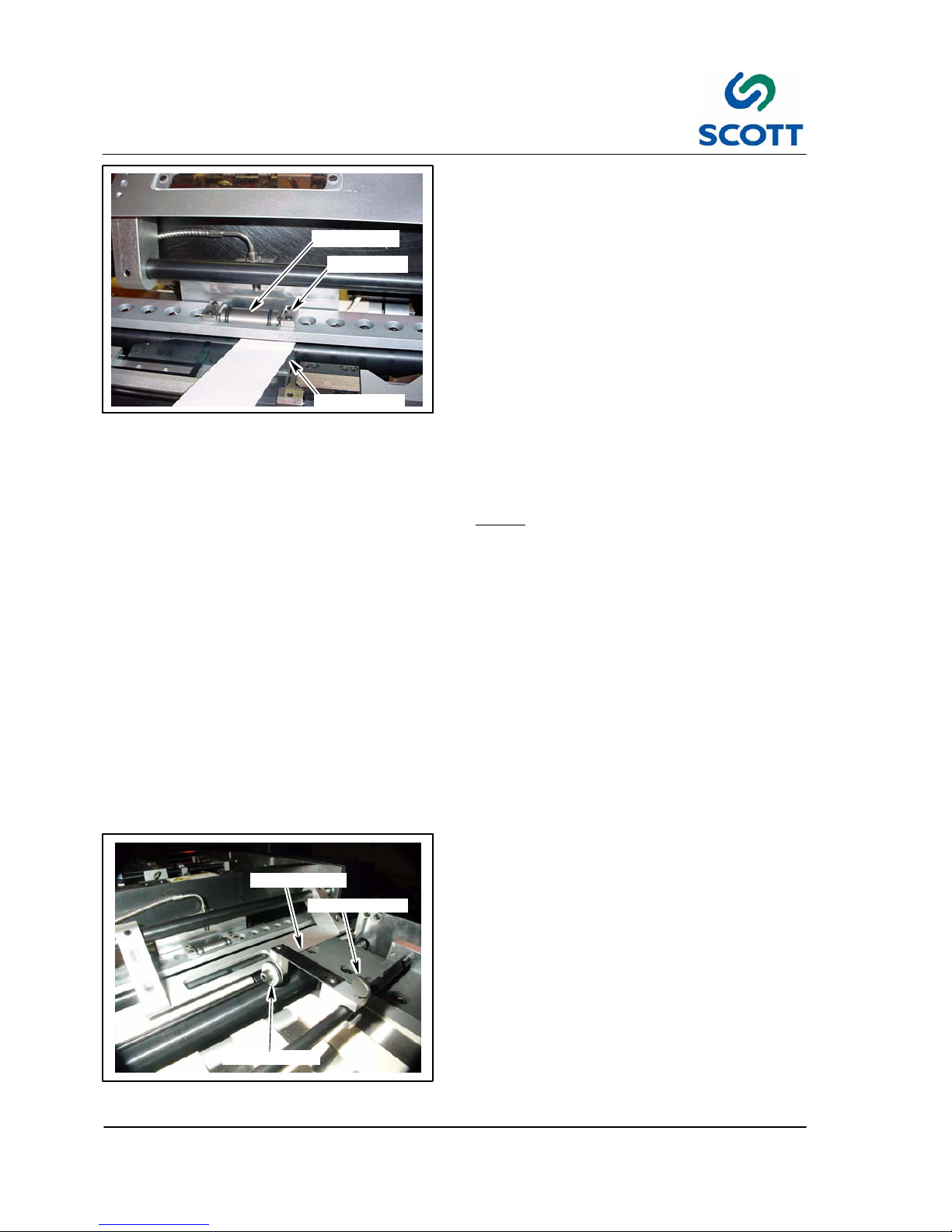
3.3.2 Adjust Hub Roller
The hub roller preforms a couple of tasks. It drives
the index stock with the Mylar into the platen press
assembly where it is kept tight against the paper
stop until the platen press seals the Mylar to the
stock and then drives it out of the platen press
assembly.
To adjust the Hub Assembly:
Step: 1. Lift the plastic window assembly.
Step: 2. Take a strip of stock that will be used
during production and cut a small strip.
Step: 3. Set the machine drive to half speed.
Step: 4. Insert the strip of stock between the black
rubber o--ring on the hub roller and the
nylon in--feed roller. You should feel a
slight tug on the stock.
Note ! If there is too much tension, the
rollers could leave marks on some
stocks. If there is not enough tension,
the stock will not leave the platen
press assembly in time for the next
piece of stock to enter.
To adjust tension:
Step: 1. Remove cover.
Step: 2. Turn the set screw clockwise for more
tension and counter--clockwise for less.
The roller must have equal tension on
both sides.
Step: 3. Replace cover.
Step: 4. Reset Machine.
Step: 5. Test tension again. Repeat if necessary.
DRIVE ROLLER
THUMB SCREW
SPRING PLATE
Fig. 3-51. Adjust Roller Drive
3.3.3 Adjust Drive Roller
To Adjust Roller Drive:
Step: 1. Loosen the the thumb screw that holds
the drive roller assembly to the mounting
bar.
Step: 2. Lightly apply pressure to the spring plate
with your fingers.
Step: 3. Retighten thumb screw.
Page 57

3 Operation
3--27
F--9999--8 Build 8 Issue 1
SIDE GUIDE
THUMB SCREW
MOUNTING BRACKET
Fig. 3-52. Side Guide Set--Up
3.3.4 Side Guide Set--Up
To adjust the Side Sheet Guide:
Step: 1. Slowly jog one piece of sheet stock
(without Mylar) up to the tab cutter.
Lower knife blade and stop the sheet.
Step: 2. Loosen the side guide thumb nut and
screw.
Step: 3. Loosen the thumb screw on the mounting
bracket and position the assembly close
to the sheet stock.
Step: 4. Tighten mounting bracket thumb screw.
Step: 5. Slowly turn the thumb screw until the side
guide just touches the side of the sheet
stock.
Note ! If the side guide is positioned too
tightly against the sheet stock it will
stop the sheet as it passes through
the conveyor. If it is positioned too far
from the sheet stock it will cause the
sheet to twist as it passed through.
Step: 6. Tighten the thumb nut on the guide.
Page 58

3 Operation
3--28
F--9999--8 Build 8 Issue 1
THUMB SCREW
KICK OUT SOLENOID
MOUNTING BRACKET
Fig. 3-53. Kick Out Solenoid Adjustment
3.3.5 Kick Out Solenoid Set--Up
Step: 1. Loosen the thumb screw on the solenoid
mounting plate.
KICK OUT SOLENOID
MOUNTING BRACKET
TAB LOC ATIO N
Fig. 3-54. Align Kick O ut Solenoid to Tab
Location
Step: 2. Position the solenoid assembly inline with
the tab location.
Step: 3. Tighten the thumb screw.
THUMB SCREW
HOLD DOWN STRAPS
Fig. 3-55. Hold Down Straps
3.3.6 Sheet Hold Down Straps
Step: 1. Loosen the thumb screws on the hold
down straps mounting block.
Step: 2. Position the straps so they are equally
divided between the end of the sheet
and the kick out solenoid.
Note ! Ifthesheetshavea“curl”tothem,
position the straps as close to the curl
as possible.
Step: 3. Tilt the straps down until they just touch
the sheet.
Too much down pressure will stop the
sheet from passing through.
Step: 4. Tighten the thumb screw.
Step: 5. Remove the sheet from the machine.
Page 59

3 Operation
3--29
F--9999--8 Build 8 Issue 1
3.3.7 Set Up For Production
PLASTIC SIZE
HANDWHEEL
PLASTIC POSITION
HANDWHEEL
TAB S IZE
HANDWHEEL
TAB POSITION
HANDWHEEL
PILE LIFT
HANDWHEEL
Fig. 3-56. Set Handwheels for Tabs
Step: 1. Use the charts in the back of this section to set the machine up for the desired tabs.
Fig. 3-57. Heater Controls
Step: 2. If laminating plastic to paper, check heat
controls to see if they have reached their
operating temperature.
Note ! The starting point for the heaters is
220- 230
_
F. This may need to be
changed depending on thickness of
stock and the length or type of plastic.
BAD CUT
HIGH
TOPPING
Fig. 3-58. Test Sheets
Step: 3. Run at least 6 test sheets of stock.
Check each sheet for:
High Topping.
● Roller tension.
● Steel ball placement.
Cut (tab and edge of stock)
● Knife blade adjustment
● Dull knives
Page 60

3 Operation
3--30
F--9999--8 Build 8 Issue 1
BAD FILM
SEAL
Fig. 3-59. Film Seal
Film Seal (adhesion to stock)
● Heat or seal time
● Bad film
● Bad paper stock
If needed make necessary adjustments and repeat
till problem is corrected.
Note ! The film may not adhere to some
coated stocks. Aqueous and
Varnished stocks tend to release gas
when laminated and cause bubbles in
the film. Also, coated stocks tend to
isolate the film from the paper not
allowing the plastic to adhere to the
paper fibers.
COUNTER
Fig. 3-60. Feeder Counter
3.3.8 Run Production
Step: 1. Set counter to desired quantity of sheets
to be run.
Step: 2. Push Counter On/Off button to start
counting.
RUN
SAFE
Fig. 3-61. Key Switch
Step: 3. Turn key switch to RUN.
RESET
Fig. 3-62. Reset Pushbutton
Step: 4. Press RESET pushbutton.
Page 61

3 Operation
3--31
F--9999--8 Build 8 Issue 1
START
Fig. 3-63. Start Pushbutton
Step: 5. Press START pushbutton.
PLASTIC
FEED
Fig. 3-64. Plastic Feed Pushbutton
Note ! If tabs are to be laminated, include
this Step. If not, skip this Step.
Step: 6. Press PLASTIC FEED pushbutton to turn
ON.
PAPER
FEED
Fig. 3-65. Paper Feed Pushbutton
Step: 7. Press PAPER FEED pushbutton to turn
ON machine for the run.
Fig. 3-66. Remove Finished Tabs
Step: 8. Adjust paper catcher to collect outgoing
stock.
Step: 9. Remove finished tabs as necessary to
prevent over filling the basket.
Page 62

3 Operation
3--32
F--9999--8 Build 8 Issue 1
Page 63

3-33
F--9999-- 8 Issue 1
3.4 Handwheel and Tab Set-Up
Page 64

3-34
F--9999-- 8 Issue 1
3.4.1 Hand Wheel and Tab Set-Up Definitions
11”
SHEET LENGTH
1/2”
MARGIN MARGIN
1 2 3
1/2”
TAB BANK
PLASTIC
SIZE
TAB
SIZE
Fig. 3-67. Chart Diagram (Example: English Measurement 3 Tab Bank, 11” Sheet Length, 1/2” Margin)
Use the definitions in the above diagram to determine hand wheel set ups.
Margin: The dimension from the top or bottom edge of the sheet to the outwardmost flat edge of the first or last tab on the page.
The top and bottom margins will be the same dimension.
Sheet Length: The overall length of the sheet of tab stock paper.
Tab Blank: The quantity of tab divisions desired on page.
Plastic Size: Dimension of plastic film applied to tab area prior to cutting.
Page 65

3-35
F--9999-- 8 Issue 1
Note ! Page intentionally left blank.
Page 66

3-36
F--9999-- 8 Issue 1
HANDWHEEL SET-UPS FOR 5” SHEET WITH3/16” MARGINS
NOTE: SHADED AREAS ARE ACHIEVED BY TURNING THE STOCK UPSIDE DOWN. THE MIDDLE TAB IS JUST TO THE LEFT OF THE SHADED AREA.
END TAB POSITIONS ONL Y ALL OTHER TAB POSITIONS
TAB BANK TAB S IZ E TABS PLASTIC
LENGTH
PLASTIC
POSITION
TAB
POSITION
PLASTIC
LENGTH
PLASTIC & TAB POSITIONS
3 1.54 1&3 2.15 1.03 .96 2.29
2
2.50
4 1.16 1&4 1.77 .84 .77 1.91
2 3
1.92 1.92
5 .93 1&5 1.54 .72 .65 1.68
2 3 4
1.57 2.50 1.57
6 .77 1&6 1.48 .64 .57 1.52
2 3 4 5
1.34 2.11 2.11 1.34
Page 67

3-37
F--9999-- 8 Issue 1
HANDWHEEL SET-UPS FOR 6” SHEET WITH3/16” MARGINS
NOTE: SHADED AREAS ARE ACHIEVED BY TURNING THE STOCK UPSIDE DOWN. THE MIDDLE TAB IS JUST TO THE LEFT OF THE SHADED AREA.
END TAB POSITIONS ONL Y ALL OTHER TAB POSITIONS
TAB BANK TAB S IZ E T ABS PLASTIC
LENGTH
PLASTIC
POSITION
TAB
POSITION
PLASTIC
LENGTH
PLASTIC & TAB POSITIONS
3 1.88 1&3 2.49 1.19 1.12 2.63 2
3.00
4 1.41 1&4 2.02 .96 .89 2.16 2 3
2.30 2.30
5 1.13 1&5 1.74 .82 .75 1.88 2 3 4
1.87 3.00 1.87
6 .94 1&6 1.55 .73 .66 1.69
2 3 4 5
1.59 2.53 2.53 1.59
Page 68

3-38
F--9999-- 8 Issue 1
HANDWHEEL SET-UPS FOR 7-1/4” SHEET WITH3/16” MARGINS
NOTE: SHADED AREAS ARE ACHIEVED BY TURNING THE STOCK UPSIDE DOWN. THE MIDDLE TAB IS JUST TO THE LEFT OF THE SHADED AREA.
END TAB POSITIONS ONL Y ALL OTHER TAB POSITIONS
TAB
BANK
TAB
SIZE
TABS
PLASTIC
LENGTH
PLASTIC
POSITION
TAB
POSITION
PLASTIC
LENGTH
PLASTIC & TAB POSITION
3 2.29 1&3 2.83 1.43 1.33 3.04 2
3.63
4 1.72 1&4 2.26 1.15 1.05 2.47 2 3
2.76 2.76
5 1.38 1&5 1.92 .93 .88 2.13 2 3 4
2.25 3.63 2.25
6 1.15 1&6 1.69 .86 .76 1.90 2 3 4 5
1.90 3.05 3.05 1.90
7 .98 1&7 1.52 .78 .68 1.73 2 3 4 5 6
1.66 2.64 3.63 2.64 1.66
8 .86 1&8 1.40 .72 .62 1.61 2 3 4 5 6 7
1.48 2.33 3.19 3.19 2.33 1.48
9 .76 1&9 1.30 .67 .57 1.51 2 3 4 5 6 7 8
1.33 2.09 2.86 3.63 2.86 2.09 1.33
10 .69 1&10 1.23 .63 .53 1.44 2 3 4 5 6 7 8 9
1.22 1.90 2.59 3.28 3.28 2.59 1.90 1.22
11 .63 1&11 1.17 .60 .50 1.38 2 3 4 5 6 7 8 9 10
1.13 1.75 2.38 3.00 3.63 3.00 2.38 1.75 1.13
12 .57 1&12 1.10 .57 .47 1.32 2 3 4 5 6 7 8 9 10 11
1.05 1.62 2.19 2.76 3.33 3.33 2.76 2.19 1.62 1.05
13 .53 1&13 1.07 .55 .45 1.28 2 3 4 5 6 7 8 9 10 11 12
.98 1.51 2.04 2.56 3.09 3.63 3.09 2.56 2.04 1.51 .98
Page 69

3-39
F--9999-- 8 Issue 1
HANDWHEEL SET-UPS FOR 7-1/4” SHEET WITH1/4” MARGINS
NOTE: SHADED AREAS ARE ACHIEVED BY TURNING THE STOCK UPSIDE DOWN. THE MIDDLE TAB IS JUST TO THE LEFT OF THE SHADED AREA.
END TAB POSITIONS ONL Y ALL OTHER TAB POSITIONS
TAB
BANK
TAB
SIZE
TABS
PLASTIC
LENGTH
PLASTIC
POSITION
TAB
POSITION
PLASTIC
LENGTH
PLASTIC & TAB POSITION
3 2.25 1&3 2.86 1.45 1.38 3.00 2
3.63
4 1.69 1&4 2.30 1.16 1.09 2.44 2 3
2.78 2.78
5 1.35 1&5 1.96 1.00 .93 2.10 2 3 4
2.28 3.63 2.28
6 1.13 1&6 1.74 .88 .81 1.88 2 3 4 5
1.94 3.06 3.06 1.94
7 .96 1&7 1.57 .80 .73 1.71 2 3 4 5 6
1.70 2.66 3.63 2.66 1.70
8 .84 1&8 1.45 .74 .67 1.59 2 3 4 5 6 7
1.51 2.36 3.20 3.20 2.36 1.51
9 .75 1&9 1.36 .70 .63 1.50 2 3 4 5 6 7 8
1.37 2.13 2.88 3.63 2.88 2.13 1.37
10 .68
1&10
1.29 .66 .59 1.43 2 3 4 5 6 7 8 9
1.26 1.94 2.61 3.29 3.29 2.61 1.94 1.26
11 .61
1&11
1.22 .63 .56 1.36 2 3 4 5 6 7 8 9 10
1.17 1.78 2.40 3.01 3.63 3.01 2.40 1.78 1.17
12 .56
1&12
1.17 .60 .53 1.31 2 3 4 5 6 7 8 9 10 11
1.09 1.66 2.22 2.78 3.34 3.34 2.78 2.22 1.66 1.09
13 .52
1&13
1.13 .58 .51 1.27 2 3 4 5 6 7 8 9 10 11 12
1.03 1.55 2.07 2.59 3.10 2.63 3.10 2.59 2.07 1.55 1.03
Page 70

3-40
F--9999-- 8 Issue 1
HANDWHEEL SET-UPS FOR 7-3/4” SHEET WITH3/16” MARGINS
NOTE: SHADED AREAS ARE ACHIEVED BY TURNING THE STOCK UPSIDE DOWN. THE MIDDLE TAB IS JUST TO THE LEFT OF THE SHADED AREA.
END TAB POSITIONS ONL Y ALL OTHER TAB POSITIONS
TAB
BANK
TAB
SIZE
TABS
PLASTIC
LENGTH
PLASTIC
POSITION
TAB
POSITION
PLASTIC
LENGTH
PLASTIC & TAB POSITION
3 2.46 1&3 3.00 1.52 1.42 3.21
2
3.88
4 1.84 1&4 2.38 1.21 1.11 2.59
2 3
2.95 2.95
5 1.47 1&5 2.01 1.02 .92 2.20
2 3 4
2.40 3.88 2.40
6 1.23 1&6 1.77 .90 .80 1.98
2 3 4 5
2.03 3.26 3.26 2.03
7 1.05 1&7 1.59 81 .71 1.80
2 3 4 5 6
1.77 2.82 3.88 2.82 1.77
8 .92 1&8 1.46 .75 .65 1.67
2 3 4 5 6 7
1.57 2.49 3.41 3.41 2.49 1.57
9 .82 1&9 1.36 .70 .60 1.57
2 3 4 5 6 7 8
1.42 2.23 3.05 3.88 3.05 2.23 1.42
10 .74
1&10
1.28 .66 .56 1.49
2 3 4 5 6 7 8 9
1.29 2.03 2.77 3.50 3.50 2.77 2.03 1.29
11 .67
1&11
1.21 .62 .52 1.42
2 3 4 5 6 7 8 9 10
1.19 1.86 2.53 3.20 3.88 3.20 2.53 1.86 1.19
12 .61
1&12
1.15 .59 .49 1.36
2 3 4 5 6 7 8 9 10 11
1.11 1.72 2.34 2.95 3.56 3.56 2.95 2.34 1.72 1.11
13 .57
1&13
1.11 .57 .47 1.32
2 3 4 5 6 7 8 9 10 11 12
1.04 1.60 2.17 2.74 3.31 3.88 3.31 2.74 2.17 1.60 1.04
14 .53
1&14
1.07 .55 .45 1.28
2 3 4 5 6 7 8 9 10 11 12 13
.98 1.50 2.03 2.55 3.08 3.61 3.61 3.08 2.55 2.03 1.50 .98
15 .50
1&15
1.04 .53 .43 1.25
2 3 4 5 6 7 8 9 10 11 12 13 14
.92 1.41 1.90 2.40 2.89 3.38 3.88 3.38 2.89 2.40 1.90 1.41 .92
Page 71

3-41
F--9999-- 8 Issue 1
HANDWHEEL SET-UPS FOR 7-3/4” SHEET WITH1/4” MARGINS
NOTE: SHADED AREAS ARE ACHIEVED BY TURNING THE STOCK UPSIDE DOWN. THE MIDDLE TAB IS JUST TO THE LEFT OF THE SHADED AREA.
END TAB POSITIONS ONL Y ALL OTHER TAB POSITIONS
TAB
BANK
TAB
SIZE
TABS
PLASTIC
LENGTH
PLASTIC
POSITION
TAB
POSITION
PLASTIC
LENGTH
PLASTIC & TAB POSITION
3 2.42
1&3
3.03 1.53 1.46 3.17
2
3.88
4 1.81
1&4
2.42 1.23 1.16 2.56
2 3
2.97 2.97
5 1.45
1&5
2.06 1.05 .98 2.20
2 3 4
2.43 3.88 2.43
6 1.21
1&6
1.82 .92 .85 1.96
2 3 4 5
2.06 3.27 3.27 2.06
7 1.04
1&7
1.65 .84 .77 1.79
2 3 4 5 6
1.80 2.84 3.88 2.84 1.80
8 .91
1&8
1.52 .77 .70 1.66
2 3 4 5 6 7
1.61 2.52 3.42 3.42 2.52 1.61
9 .81
1&9
1.42 .72 .65 1.56
2 3 4 5 6 7 8
1.46 2.26 3.07 3.88 3.07 2.26 1.46
10 .73
1&10
1.34 .68 .61 1.48
2 3 4 5 6 7 8 9
1.34 2.06 2.79 3.51 3.51 2.79 2.06 1.34
11 .66
1&11
1.27 .65 .58 1.41
2 3 4 5 6 7 8 9 10
1.24 1.90 2.56 3.22 3.88 3.22 2.56 1.90 1.24
12 .60
1&12
1.21 .62 .55 1.35
2 3 4 5 6 7 8 9 10 11
1.16 1.76 2.36 2.97 3.57 3.57 2.97 2.36 1.76 1.16
13 .56
1&13
1.17 .60 .53 1.31
2 3 4 5 6 7 8 9 10 11 12
1.09 1.64 2.20 2.76 3.31 3.88 3.31 2.76 2.20 1.64 1.09
14 .52
1&14
1.13 .58 .51 1.27
2 3 4 5 6 7 8 9 10 11 12 13
1.03 1.54 2.06 2.58 3.09 3.61 3.61 3.09 2.58 2.06 1.54 1.03
15 .48
1&15
1.09 .56 .49 1.23
2 3 4 5 6 7 8 9 10 11 12 13 14
.97 1.46 1.94 2.42 2.91 3.39 3.88 3.39 2.91 2.42 1.94 1.46 .97
Page 72

3-42
F--9999-- 8 Issue 1
HANDWHEEL SET-UPS FOR 8” SHEET WITH3/16” MARGINS
NOTE: SHADED AREAS ARE ACHIEVED BY TURNING THE STOCK UPSIDE DOWN. THE MIDDLE TAB IS JUST TO THE LEFT OF THE SHADED AREA.
END TAB POSITIONS ONL Y ALL OTHER TAB POSITIONS
TAB BANK TAB SI ZE TABS PLASTIC
LENGTH
PLASTIC
POSITION
TAB
POSITION
PLASTIC
LENGTH
PLASTIC & TAB POSITION
3 2.54 1&3 3.15 1.53 1.46 3.29 2
4.00
4 1.91 1&4 2.52 1.21 1.14 2.66 2 3
3.05 3.05
5 1.53 1&5 2.14 1.02 .95 2.28 2 3 4
2.47 4.00 2.47
6 1.27 1&6 1.88 .89 .82 2.02 2 3 4 5
2.09 3.36 3.36 2.09
Page 73

3-43
F--9999-- 8 Issue 1
HANDWHEEL SET-UPS FOR 8-1/2” SHEET WITH3/16” MARGINS
NOTE: SHADED AREAS ARE ACHIEVED BY TURNING THE STOCK UPSIDE DOWN. THE MIDDLE TAB IS JUST TO THE LEFT OF THE SHADED AREA.
END TAB POSITIONS ONL Y ALL OTHER TAB POSITIONS
TAB
BANK
TAB
SIZE
TABS
PLASTIC
LENGTH
PLASTIC
POSITION
TAB
POSITION
PLASTIC
LENGTH
PLASTIC & TAB POSITION
3 2.71
1&3
3.25 1.64 1.54 3.46
2
4.25
4 2.03
1&4
2.57 1.30 1.20 2.78
2 3
3.23 3.23
5 1.63
1&5
2.17 1.10 1.00 2.38
2 3 4
2.62 4.25 2.62
6 1.35
1&6
1.89 .96 .86 2.10
2 3 4 5
2.22 3.57 3.57 2.22
7 1.16
1&7
1.70 .87 .77 1.91
2 3 4 5 6
1.93 3.09 4.25 3.09 1.93
8 1.01
1&8
1.55 .79 .69 1.76
2 3 4 5 6 7
1.71 2.72 3.74 3.74 2.72 1.71
9 .90
1&9
1.44 .74 .64 1.65
2 3 4 5 6 7 8
1.54 2.44 3.34 4.25 3.34 2.44 1.54
10 .81
1&10
1.35 .69 .59 1.56
2 3 4 5 6 7 8 9
1.41 2.22 3.03 3.84 3.84 3.03 2.22 1.41
11 .74
1&11
1.28 .66 .56 1.49
2 3 4 5 6 7 8 9 10
1.29 2.03 2.77 3.51 4.25 3.51 2.77 2.03 1.29
12 .68
1&12
1.22 .63 .53 1.43
2 3 4 5 6 7 8 9 10 11
1.20 1.88 2.56 3.23 3.91 3.91 3.23 2.56 1.88 1.20
13 .63
1&13
1.17 .60 .50 1.38
2 3 4 5 6 7 8 9 10 11 12
1.13 1.75 2.38 3.00 3.62 4.25 3.62 3.00 2.38 1.75 1.13
14 .58
1&14
1.12 .58 .48 1.33
2 3 4 5 6 7 8 9 10 11 12 13
1.06 1.64 2.22 2.80 3.38 3.96 3.96 3.38 2.80 2.22 1.64 1.06
15 .54
1&15
1.08 .56 .46 1.29
2 3 4 5 6 7 8 9 10 11 12 13 14
1.00 1.54 2.08 2.62 3.16 3.70 4.25 3.70 3.16 2.62 2.08 1.54 1.00
Page 74

3-44
F--9999-- 8 Issue 1
HANDWHEEL SET-UPS FOR 8-1/2” SHEET WITH1/4” MARGINS
NOTE: SHADED AREAS ARE ACHIEVED BY TURNING THE STOCK UPSIDE DOWN. THE MIDDLE TAB IS JUST TO THE LEFT OF THE SHADED AREA.
END TAB POSITIONS ONL Y ALL OTHER TAB POSITIONS
TAB
BANK
TAB
SIZE
TABS
PLASTIC
LENGTH
PLASTIC
POSITION
TAB
POSITION
PLASTIC
LENGTH
PLASTIC & TAB POSITION
3 2.67
1&3
3.28 1.65 1.58 3.42
2
4.25
4 2.00
1&4
2.61 1.32 1.25 2.75
2 3
3.25 3.25
5 1.60
1&5
2.21 1.12 1.05 2.35
2 3 4
2.65 4.25 2.65
6 1.33
1&6
1.94 .99 .92 2.08
2 3 4 5
2.25 3.58 3.58 2.25
7 1.14
1&7
1.75 .89 .82 1.89
2 3 4 5 6
1.96 3.10 4.25 3.10 1.96
8 1.00
1&8
1.61 .82 .75 1.75
2 3 4 5 6 7
1.75 2.75 3.75 3.75 2.75 1.75
9 .89
1&9
1.50 .76 .69 1.64
2 3 4 5 6 7 8
1.58 2.47 3.36 4.25 3.36 2.47 1.58
10 .80
1&10
1.41 .72 .65 1.55
2 3 4 5 6 7 8 9
1.45 2.25 3.05 3.85 3.85 3.05 2.25 1.45
11 .73
1&11
1.34 .68 .61 1.48
2 3 4 5 6 7 8 9 10
1.34 2.07 2.79 3.52 4.25 3.52 2.79 2.07 1.34
12 .67
1&12
1.28 .65 .58 1.42
2 3 4 5 6 7 8 9 10 11
1.25 1.92 2.58 3.25 3.91 3.91 3.25 2.58 1.92 1.25
13 .62
1&13
1.23 .73 .56 1.37
2 3 4 5 6 7 8 9 10 11 12
1.17 1.79 2.40 3.02 3.63 4.25 3.63 3.02 2.40 1.79 1.17
14 .57
1&14
1.18 .61 .54 1.32
2 3 4 5 6 7 8 9 10 11 12 13
1.11 1.68 2.25 2.82 3.39 3.96 3.96 3.39 2.82 2.25 1.68 1.11
15 .53
1&15
1.14 .59 .52 1.28
2 3 4 5 6 7 8 9 10 11 12 13 14
1.05 1.58 2.12 2.65 3.18 3.71 4.25 3.71 3.18 2.65 2.12 1.58 1.05
Page 75

3-45
F--9999-- 8 Issue 1
HANDWHEEL SET-UPS FOR 8-1/2” SHEET WITH1/2” MARGINS
NOTE: SHADED AREAS ARE ACHIEVED BY TURNING THE STOCK UPSIDE DOWN. THE MIDDLE TAB IS JUST TO THE LEFT OF THE SHADED AREA.
PLASTIC POSITIONS & TAB POSITION
TAB
BANK
TAB
SIZE
PLASTIC
SIZE
PLASTICPOSITIONS&TABPOSITIO
N
HANDWHEEL DIMENSION
2 3.75 4.50
1 2
2.38 2.38
3 2.50 3.25
1 2 3
1.75 4.25 1.75
4 1.88 2.63
1 2 3 4
1.44 3.31 3.31 1.44
5 1.50 2.25
1 2 3 4 5
1.25 2.75 4.25 2.75 1.25
6 1.25 2.00
1 2 3 4 5 6
1.13 2.38 3.63 3.63 2.38 1.13
7 1.07 1.82
1 2 3 4 5 6 7
1.04 2.11 3.18 4.25 3.18 2.11 1.04
8 .94 1.69
1 2 3 4 5 6 7 8
.97 1.91 2.84 3.78 3.78 2.84 1.91 .97
9 .83 1.58
1 2 3 4 5 6 7 8 9
.92 1.75 2.58 3.42 4.25 3.42 2.58 1.75 .92
10 .75 1.50
1 2 3 4 5 6 7 8 9 10
.88 1.63 2.38 3.13 3.88 3.88 3.13 2.38 1.63 .88
11 .68 1.43
1 2 3 4 5 6 7 8 9 10 11
.84 1.52 2.20 2.88 3.56 4.25 3.56 2.88 2.20 1.52 .84
12 .63 1.38
1 2 3 4 5 6 7 8 9 10 11 12
.81 1.44 2.06 2.69 3.31 3.94 3.94 3.31 2.69 2.06 1.44 .81
13 .58 1.33
1 2 3 4 5 6 7 8 9 10 11 12 13
.79 1.36 1.94 2.52 3.09 3.67 4.25 3.67 3.09 2.52 1.94 1.36 .79
14 .54 1.29
1 2 3 4 5 6 7 8 9 10 11 12 13 14
.77 1.30 1.84 2.37 2.91 3.44 3.98 3.98 3.44 2.91 2.37 1.84 1.30 .77
15 .50 1.25
1 2 3 4 5 6 7 8 9 10 11 12 13 14 15
.75 1.25 1.75 2.25 2.75 3.25 3.75 4.25 3.75 3.25 2.75 2.25 1.75 1.25 .75
Page 76

3-46
F--9999-- 8 Issue 1
HANDWHEEL SET-UPS FOR 9” SHEET WITH3/16” MARGINS
NOTE: SHADED AREAS ARE ACHIEVED BY TURNING THE STOCK UPSIDE DOWN. THE MIDDLE TAB IS JUST TO THE LEFT OF THE SHADED AREA.
END TAB POSITIONS ONL Y ALL OTHER TAB POSITIONS
TAB BANK TAB SI ZE TABS PLASTIC
LENGTH
PLASTIC
POSITION
TAB
POSITION
PLASTIC
LENGTH
PLASTIC & TAB POSITION
3 2.88 1&3 3.49 1.70 1.63 3.63 2
4.50
4 2.16 1&4 2.77 1.34 1.27 2.91 2 3
3.42 3.42
5 1.73 1&5 2.34 1.12 1.05 2.48 2 3 4
2.75 4.50 2.75
6 1.44 1&6 2.05 .98 .91 2.19 2 3 4 5
2.34 3.78 3.78 2.34
Page 77

3-47
F--9999-- 8 Issue 1
HANDWHEEL SET-UPS FOR 9-1/2” SHEET WITH3/16” MARGINS
NOTE: SHADED AREAS ARE ACHIEVED BY TURNING THE STOCK UPSIDE DOWN. THE MIDDLE TAB IS JUST TO THE LEFT OF THE SHADED AREA.
END TAB POSITIONS ONL Y ALL OTHER TAB POSITIONS
TAB
BANK
TAB
SIZE
TABS
PLASTIC
LENGTH
PLASTIC
POSITION
TAB
POSITION
PLASTIC
LENGTH
PLASTIC & TAB POSITION
3 3.04
1&3
3.58 1.81 1.71 3.79
2
4.75
4 2.28
1&4
2.82 1.43 1.33 3.03
2 3
3.61 3.61
5 1.83
1&5
2.37 1.20 1.10 2.58
2 3 4
2.92 4.75 2.92
6 1.52
1&6
2.06 1.05 .95 2.27
2 3 4 5
2.47 3.99 3.99 2.47
7 1.30
1&7
1.84 .94 .84 2.05
2 3 4 5 6
2.14 3.44 4.75 3.44 2.14
8 1.14
1&8
1.68 .86 .76 1.89
2 3 4 5 6 7
1.90 3.04 4.18 4.18 3.04 1.90
9 1.01
1&9
1.55 .79 .69 1.76
2 3 4 5 6 7 8
1.71 2.72 3.73 4.75 3.73 2.72 1.71
10 .91
1&10
1.45 .74 .64 1.66
2 3 4 5 6 7 8 9
1.56 2.47 3.38 4.29 4.29 3.38 2.47 1.56
11 .83
1&11
1.37 .70 .60 1.58
2 3 4 5 6 7 8 9 10
1.43 2.26 3.09 3.92 4.75 3.92 3.09 2.26 1.43
12 .76
1&12
1.30 .67 .57 1.51
2 3 4 5 6 7 8 9 10 11
1.33 2.09 2.85 3.61 4.37 4.37 3.61 2.85 2.09 1.33
13 .70
1&13
1.24 .64 .54 1.45
2 3 4 5 6 7 8 9 10 11 12
1.24 1.94 2.64 3.34 4.04 4.75 4.04 3.34 2.64 1.94 1.24
14 .65
1&14
1.19 .61 .51 1.40
2 3 4 5 6 7 8 9 10 11 12 13
1.16 1.81 2.47 3.12 3.77 4.42 4.42 3.77 3.12 2.47 1.81 1.16
15 .61
1&15
1.15 .59 .49 1.36
2 3 4 5 6 7 8 9 10 11 12 13 14
1.10 1.71 2.32 2.92 3.53 4.14 4.75 4.14 3.53 2.92 2.32 1.71 1.10
Page 78

3-48
F--9999-- 8 Issue 1
HANDWHEEL SET-UPS FOR 9-1/2” SHEET WITH1/4” MARGINS
NOTE: SHADED AREAS ARE ACHIEVED BY TURNING THE STOCK UPSIDE DOWN. THE MIDDLE TAB IS JUST TO THE LEFT OF THE SHADED AREA.
END TAB POSITIONS ONL Y ALL OTHER TAB POSITIONS
TAB
BANK
TAB
SIZE
TABS
PLASTIC
LENGTH
PLASTIC
POSITION
TAB
POSITION
PLASTIC
LENGTH
PLASTIC & TAB POSITION
3 3.00
1&3
3.61 1.83 1.75 3.75
2
4.75
4 2.25
1&4
2.86 1.46 1.38 3.00
2 3
3.63 3.63
5 1.80
1&5
2.41 1.23 1.15 2.55
2 3 4
2.95 4.75 2.95
6 1.50
1&6
2.11 1.08 1.00 2.25
2 3 4 5
2.50 4.00 4.00 2.50
7 1.29
1&7
1.90 .97 .89 2.04
2 3 4 5 6
2.18 3.46 4.75 3.46 2.18
8 1.13
1&8
1.74 .89 .81 1.89
2 3 4 5 6 7
1.94 3.06 4.19 4.19 3.06 1.94
9 1.00
1&9
1.61 .83 .75 1.75
2 3 4 5 6 7 8
1.75 2.75 3.75 4.75 3.75 2.75 1.75
10 .90
1&10
1.51 .78 .70 1.65
2 3 4 5 6 7 8 9
1.60 2.50 3.40 4.30 4.30 3.40 2.50 1.60
11 .82
1&11
1.43 .73 .66 1.57
2 3 4 5 6 7 8 9 10
1.48 2.30 3.11 3.93 4.75 3.93 3.11 2.30 1.48
12 .75
1&12
1.36 .70 .62 1.50
2 3 4 5 6 7 8 9 10 11
1.38 2.13 2.88 3.63 4.38 4.38 3.63 2.88 2.13 1.38
13 .69
1&13
1.30 .68 .60 1.44
2 3 4 5 6 7 8 9 10 11 12
1.29 1.98 2.67 3.36 4.06 4.75 4.06 3.36 2.67 1.98 1.29
14 .64
1&14
1.25 .65 .57 1.39
2 3 4 5 6 7 8 9 10 11 12 13
1.21 1.86 2.50 3.14 3.78 4.42 4.42 3.78 3.14 2.50 1.86 1.21
15 .60
1&15
1.21 .63 .55 1.35
2 3 4 5 6 7 8 9 10 11 12 13 14
1.15 1.75 2.35 2.95 3.55 4.15 4.75 4.15 3.55 2.95 2.35 1.75 1.15
Page 79

3-49
F--9999-- 8 Issue 1
HANDWHEEL SET-UPS FOR 9-1/2” SHEET WITH1/2” MARGINS
NOTE: SHADED AREAS ARE ACHIEVED BY TURNING THE STOCK UPSIDE DOWN. THE MIDDLE TAB IS JUST TO THE LEFT OF THE SHADED AREA.
TAB
TAB
PLASTIC
PLASTIC POSITIONS & TAB POSITION
BANKSIZE SIZE
PLASTICPOSITIONS&TABPOSITIO
N
HANDWHEEL DIMENSION
2 4.25 5.00
1 2
2.63 2.63
3 2.83 3.58
1 2 3
1.92 4.75 1.92
4 2.13 2.88
1 2 3 4
1.56 3.68 3.68 1.56
5 1.70 2.45
1 2 3 4 5
1.35 3.05 4.75 3.05 1.35
6 1.42 2.17
1 2 3 4 5 6
1.21 2.63 4.04 4.04 2.63 1.21
7 1.21 1.96
1 2 3 4 5 6 7
1.11 2.32 3.54 4.75 3.54 2.32 1.11
8 1.06 1.81
1 2 3 4 5 6 7 8
1.03 2.09 3.16 4.22 4.22 3.16 2.09 1.03
9 .94 1.69
1 2 3 4 5 6 7 8 9
.97 1.92 2.86 3.80 4.75 3.80 2.86 1.92 .97
10 .85 1.60
1 2 3 4 5 6 7 8 9 10
.93 1.78 2.63 3.48 4.33 4.33 3.48 2.63 1.78 .93
11 .77 1.52
1 2 3 4 5 6 7 8 9 10 11
.89 1.66 2.43 3.20 3.97 4.75 3.97 3.20 2.43 1.66 .89
12 .71 1.46
1 2 3 4 5 6 7 8 9 10 11 12
.85 1.56 2.27 2.98 3.69 4.39 4.39 3.69 2.98 2.27 1.56 .85
13 .65 1.40
1 2 3 4 5 6 7 8 9 10 11 12 13
.83 1.48 2.13 2.79 3.44 4.09 4.75 4.09 3.44 2.79 2.13 1.48 .83
14 .61 1.36
1 2 3 4 5 6 7 8 9 10 11 12 13 14
.80 1.41 2.02 2.62 3.23 3.84 4.45 4.45 3.84 3.23 2.62 2.02 1.41 .80
15 .57 1.32
1 2 3 4 5 6 7 8 9 10 11 12 13 14 15
.78 1.35 1.92 2.48 3.05 3.61 4.18 4.75 4.18 3.61 3.05 2.48 1.92 1.35 .78
Page 80

3-50
F--9999-- 8 Issue 1
HANDWHEEL SET-UPS FOR 11” SHEET WITH1/8” MARGINS
NOTE: SHADED AREAS ARE ACHIEVED BY TURNING THE STOCK UPSIDE DOWN. THE MIDDLE TAB IS JUST TO THE LEFT OF THE SHADED AREA.
END TAB POSITIONS ONL Y ALL OTHER TAB POSITIONS
TAB
BANK
TAB
SIZE
TABS
PLASTIC
LENGTH
PLASTIC
POSITION
TAB
POSITION
PLASTIC
LENGTH
PLASTIC & TAB POSITIONS
3 3.58 1&3 4.08 2.06 1.91 4.33
2
5.50
4 2.69 1&4 3.19 1.61 1.47 3.44
2 3
4.16 4.16
5 2.15 1&5 2.65 1.35 1.20 2.90
2 3 4
3.35 5.50 3.35
6 1.79 1&6 2.29 1.17 1.02 2.54
2 3 4 5
2.81 4.60 4.60 2.81
7 1.54 1&7 2.04 1.04 .89 2.29
2 3 4 5 6
2.43 3.97 5.50 3.97 2.43
8 1.34 1&8 1.84 .94 .79 2.09
2 3 4 5 6 7
2.14 3.49 4.84 4.84 3.49 2.14
9 1.19 1&9 1.69 .87 .72 1.94
2 3 4 5 6 7 8
1.91 3.10 4.30 5.50 4.30 3.10 1.91
10 1.07 1&10 1.57 .80 .66 1.82
2 3 4 5 6 7 8 9
1.74 2.81 3.89 4.96 4.96 3.89 2.81 1.74
11 .98 1&11 1.48 .76 .60 1.73
2 3 4 5 6 7 8 9 10
1.58 2.56 3.54 4.52 5.50 4.52 3.54 2.56 1.58
12 .90 1&12 1.40 .72 .56 1.65
2 3 4 5 6 7 8 9 10 11
1.46 2.36 3.26 4.16 5.06 5.06 4.16 3.26 2.36 1.46
13 .83 1&13 1.33 .69 .53 1.58
2 3 4 5 6 7 8 9 10 11 12
1.36 2.19 3.02 3.85 4.68 5.50 4.68 3.85 3.02 2.19 1.36
14 .77 1&14 1.27 .66 .50 1.52
2 3 4 5 6 7 8 9 10 11 12 13
1.27 2.04 2.81 3.58 4.35 5.12 5.12 4.35 3.58 2.81 2.04 1.27
15 .72 1&15 1.22 .63 .47 1.47
2 3 4 5 6 7 8 9 10 11 12 13 14
1.19 1.91 2.63 3.35 4.07 4.79 5.50 4.79 4.07 3.35 2.63 1.91 1.19
Page 81

3-51
F--9999-- 8 Issue 1
HANDWHEEL SET-UPS FOR 11” SHEET WITH3/16” MARGINS
NOTE: SHADED AREAS ARE ACHIEVED BY TURNING THE STOCK UPSIDE DOWN. THE MIDDLE TAB IS JUST TO THE LEFT OF THE SHADED AREA.
END TAB POSITIONS ONL Y ALL OTHER TAB POSITIONS
TAB
BANK
TAB
SIZE
TABS
PLASTIC
LENGTH
PLASTIC
POSITION
TAB
POSITION
PLASTIC
LENGTH
PLASTIC & TAB POSITION
3 3.54
1&3
4.08 2.05 1.95 4.29
2
5.50
4 2.66
1&4
3.20 1.61 1.51 3.41
2 3
4.17 4.17
5 2.13
1&5
2.67 1.35 1.25 2.88
2 3 4
3.36 5.50 3.36
6 1.77
1&6
2.31 1.17 1.07 2.52
2 3 4 5
2.84 4.61 4.61 2.84
7 1.52
1&7
2.06 1.04 .94 2.27
2 3 4 5 6
2.46 3.98 5.50 3.98 2.46
8 1.33
1&8
1.87 .94 .84 2.08
2 3 4 5 6 7
2.17 3.50 4.83 4.83 3.50 2.17
9 1.18
1&9
1.72 .87 .77 1.93
2 3 4 5 6 7 8
1.95 3.13 4.31 5.50 4.31 3.13 1.95
10 1.06
1&10
1.60 .82 .72 1.81
2 3 4 5 6 7 8 9
1.78 2.84 3.90 4.96 4.96 3.90 2.84 1.78
11 .97
1&11
1.51 .76 .66 1.72
2 3 4 5 6 7 8 9 10
1.62 2.59 3.56 4.54 5.50 4.54 3.56 2.59 1.62
12 .89
1&12
1.43 .73 .63 1.64
2 3 4 5 6 7 8 9 10 11
1.52 2.41 3.30 4.18 5.06 5.06 4.18 3.30 2.41 1.52
13 .82
1&13
1.36 .69 .59 1.57
2 3 4 5 6 7 8 9 10 11 12
1.41 2.23 3.05 3.87 4.69 5.50 4.69 3.87 3.05 2.23 1.41
14 .76
1&14
1.30 .66 .56 1.51
2 3 4 5 6 7 8 9 10 11 12 13
1.32 2.08 2.84 3.60 4.36 5.12 5.12 4.36 3.60 2.84 2.08 1.32
15 .71
1&15
1.25 .64 .54 1.46
2 3 4 5 6 7 8 9 10 11 12 13 14
1.25 1.96 2.67 3.38 4.09 4.80 5.50 4.80 4.09 3.38 2.67 1.96 1.25
Page 82

3-52
F--9999-- 8 Issue 1
HANDWHEEL SET-UPS FOR 11” SHEET WITH1/4” MARGINS
NOTE: SHADED AREAS ARE ACHIEVED BY TURNING THE STOCK UPSIDE DOWN. THE MIDDLE TAB IS JUST TO THE LEFT OF THE SHADED AREA.
END TAB POSITIONS ONL Y ALL OTHER TAB POSITIONS
TAB
BANK
TAB
SIZE
TABS
PLASTIC
LENGTH
PLASTIC
POSITION
TAB
POSITION
PLASTIC
LENGTH
PLASTIC & TAB POSITION
3 3.50
1&3
4.11 2.07 2.00 4.25
2
5.50
4 2.62
1&4
3.23 1.63 1.56 3.37
2 3
4.18 4.18
5 2.10
1&5
2.71 1.37 1.30 2.85
2 3 4
3.40 5.50 3.40
6 1.75
1&6
2.36 1.19 1.12 2.50
2 3 4 5
2.87 4.62 4.62 2.87
7 1.50
1&7
2.11 1.07 1.00 2.25
2 3 4 5 6
2.50 4.00 5.50 4.00 2.50
8 1.31
1&8
1.92 .97 .90 2.06
2 3 4 5 6 7
2.21 3.52 4.83 4.83 3.52 2.21
9 1.17
1&9
1.78 .90 .83 1.92
2 3 4 5 6 7 8
2.00 3.17 4.34 5.50 4.34 3.17 2.00
10 1.05
1&10
1.66 .84 .77 1.80
2 3 4 5 6 7 8 9
1.82 2.87 3.92 4.97 4.97 3.92 2.87 1.82
11 .95
1&11
1.56 .79 .72 1.70
2 3 4 5 6 7 8 9 10
1.67 2.62 3.58 4.54 5.50 4.54 3.58 2.62 1.67
12 .87
1&12
1.48 .75 .68 1.62
2 3 4 5 6 7 8 9 10 11
1.55 2.42 3.30 4.18 5.06 5.06 4.18 3.30 2.42 1.55
13 .80
1&13
1.41 .72 .65 1.55
2 3 4 5 6 7 8 9 10 11 12
1.46 2.27 3.08 3.89 4.70 5.50 4.70 3.89 3.08 2.27 1.46
14 .75
1&14
1.36 .69 .62 1.50
2 3 4 5 6 7 8 9 10 11 12 13
1.38 2.12 2.88 3.62 4.37 5.12 5.12 4.37 3.62 2.88 2.12 1.38
15 .70
1&15
1.31 .67 .60 1.45
2 3 4 5 6 7 8 9 10 11 12 13 14
1.30 2.00 2.70 3.40 4.10 4.80 5.50 4.80 4.10 3.40 2.70 2.00 1.30
Page 83

3-53
F--9999-- 8 Issue 1
HANDWHEEL SET-UPS FOR 11” SHEET WITH1/2” MARGINS
NOTE: SHADED AREAS ARE ACHIEVED BY TURNING THE STOCK UPSIDE DOWN. THE MIDDLE TAB IS JUST TO THE LEFT OF THE SHADED AREA.
TAB
TAB
PLASTIC
PLASTIC POSITIONS & TAB POSITION
BANKSIZE SIZE
PLASTICPOSITIONS&TABPOSITIO
N
HANDWHEEL DIMENSION
2 5.00 5.75
1 2
25.005.75
3.00 3.00
3 3.34 4.08
1 2 3
33.344.08
2.17 5.50 2.17
4 2.50 3.25
1 2 3 4
42.503.25
1.75 4.25 4.25 1.75
5 2.00 2.75
1 2 3 4 5
52.002.75
1.50 3.50 5.50 3.50 1.50
6 1.66 2.41
1 2 3 4 5 6
61.662.41
1.33 3.00 4.66 4.66 3.00 1.33
7 1.43 2.18
1 2 3 4 5 6 7
71.432.18
1.21 2.64 4.07 5.50 4.07 2.64 1.21
8 1.25 2.00
1 2 3 4 5 6 7 8
81.252.00
1.13 2.38 3.63 4.88 4.88 3.63 2.38 1.13
9 1.11 1.86
1 2 3 4 5 6 7 8 9
91.111.86
1.06 2.17 3.28 4.39 5.50 4.39 3.28 2.17 1.06
10 1.00 1.75
1 2 3 4 5 6 7 8 9 10
101.001.7
5
1.00 2.00 3.00 4.00 5.00 5.00 4.00 3.00 2.00 1.00
.91 1.66
1 2 3 4 5 6 7 8 9 10 11
11.911.66
.96 1.87 2.78 3.69 4.60 5.50 4.60 3.69 2.78 1.87 .96
12 .83 1.58
1 2 3 4 5 6 7 8 9 10 11 12
12.831.58
.92 1.75 2.58 3.41 4.24 5.07 5.07 4.24 3.41 2.58 1.75 .92
13 .77 1.52
1 2 3 4 5 6 7 8 9 10 11 12 13
13.771.52
.89 1.66 2.43 3.20 3.97 4.74 5.50 4.74 3.97 3.20 2.43 1.66 .89
14 .71 1.46
1 2 3 4 5 6 7 8 9 10 11 12 13 14
14.711.46
.85 1.57 2.28 2.99 3.70 4.41 5.12 5.12 4.41 3.70 2.99 2.28 1.57 .85
15 .67 1.42
1 2 3 4 5 6 7 8 9 10 11 12 13 14 15
15.671.42
.82 1.49 2.16 2.83 3.50 4.17 4.84 5.50 4.84 4.17 3.50 2.83 2.16 1.49 .82
Page 84

3-54
F--9999-- 8 Issue 1
HANDWHEEL SET-UPS FOR 12” SHEET WITH3/16” MARGINS
NOTE: SHADED AREAS ARE ACHIEVED BY TURNING THE STOCK UPSIDE DOWN. THE MIDDLE TAB IS JUST TO THE LEFT OF THE SHADED AREA.
END TAB POSITIONS ONL Y ALL OTHER TAB POSITIONS
TAB
BANK
TAB
SIZE
TABS
PLASTIC
LENGTH
PLASTIC
POSITION
TAB
POSITION
PLASTIC
LENGTH
PLASTIC & TAB POSITION
3 3.87
1&3
4.41 2.22 2.12 4.62
2
6.00
4 2.91
1&4
3.45 1.74 1.64 3.66
2 3
4.55 4.55
5 2.33
1&5
2.87 1.45 1.35 3.08
2 3 4
3.67 6.00 3.67
6 1.94
1&6
2.48 1.26 1.16 2.69
2 3 4 5
3.09 5.03 5.03 3.09
7 1.66
1&7
2.20 1.12 1.02 2.41
2 3 4 5 6
2.68 4.34 6.00 4.34 2.68
8 1.45
1&8
1.99 1.01 .91 2.20
2 3 4 5 6 7
2.37 3.82 5.27 5.27 3.82 2.37
9 1.29
1&9
1.83 .93 .83 2.04
2 3 4 5 6 7 8
2.12 3.41 4.70 6.00 4.70 3.41 2.12
10 1.16
1&10
1.70 .87 .77 1.91
2 3 4 5 6 7 8 9
1.93 3.09 4.25 5.42 5.42 4.25 3.09 1.93
11 1.06
1&11
1.60 .81 .71 1.81
2 3 4 5 6 7 8 9 10
1.77 2.83 3.88 4.94 6.00 4.94 3.88 2.83 1.77
12 .97
1&12
1.51 .77 .67 1.72
2 3 4 5 6 7 8 9 10 11
1.64 2.61 3.58 4.54 5.51 5.51 4.54 3.58 2.61 1.64
13 .89
1&13
1.43 .73 .63 1.64
2 3 4 5 6 7 8 9 10 11 12
1.53 2.42 3.32 4.21 5.10 6.00 5.10 4.21 3.32 2.42 1.53
14 .83
1&14
1.37 .70 .60 1.58
2 3 4 5 6 7 8 9 10 11 12 13
1.43 2.26 3.09 3.92 4.75 5.58 5.58 4.75 3.92 3.09 2.26 1.43
15 .77
1&15
1.31 .67 .57 1.52
2 3 4 5 6 7 8 9 10 11 12 13 14
1.35 2.12 2.90 3.67 4.45 5.22 6.00 5.22 4.45 3.67 2.90 2.12 1.35
Page 85

3-55
F--9999-- 8 Issue 1
HANDWHEEL SET-UPS FOR 12” SHEET WITH1/4” MARGINS
NOTE: SHADED AREAS ARE ACHIEVED BY TURNING THE STOCK UPSIDE DOWN. THE MIDDLE TAB IS JUST TO THE LEFT OF THE SHADED AREA.
END TAB POSITIONS ONL Y ALL OTHER TAB POSITIONS
TAB
BANK
TAB
SIZE
TABS
PLASTIC
LENGTH
PLASTIC
POSITION
TAB
POSITION
PLASTIC
LENGTH
PLASTIC & TAB POSITION
3 3.83
1&3
4.44 2.24 2.17 4.58
2
6.00
4 2.87
1&4
3.48 1.75 1.68 3.62
2 3
4.56 4.56
5 2.30
1&5
2.91 1.47 1.40 3.05
2 3 4
3.70 6.00 3.70
6 1.92
1&6
2.53 1.28 1.21 2.67
2 3 4 5
3.12 5.04 5.04 3.12
7 1.64
1&7
2.25 1.14 1.07 2.39
2 3 4 5 6
2.71 4.36 6.00 4.36 2.71
8 1.44
1&8
2.05 .96 .97 2.19
2 3 4 5 6 7
2.41 3.84 5.28 5.28 3.84 2.41
9 1.28
1&9
1.89 .94 .89 2.03
2 3 4 5 6 7 8
2.17 3.44 4.72 6.00 4.72 3.44 2.17
10 1.15
1&10
1.76 .90 .83 1.90
2 3 4 5 6 7 8 9
1.98 3.13 4.28 5.43 5.43 4.28 3.13 1.98
11 1.04
1&11
1.65 .84 .77 1.79
2 3 4 5 6 7 8 9 10
1.82 2.86 3.91 4.95 6.00 4.95 3.91 2.86 1.82
12 .96
1&12
1.57 .80 .73 1.71
2 3 4 5 6 7 8 9 10 11
1.69 2.65 3.60 4.56 5.52 5.52 4.56 3.60 2.65 1.69
13 .88
1&13
1.49 .76 .69 1.63
2 3 4 5 6 7 8 9 10 11 12
1.58 2.46 3.34 4.23 5.11 6.00 5.11 4.23 3.34 2.46 1.58
14 .82
1&14
1.43 .73 .66 1.57
2 3 4 5 6 7 8 9 10 11 12 13
1.48 2.30 3.12 3.94 4.77 5.59 5.59 4.77 3.94 3.12 2.30 1.48
15 .77
1&15
1.38 .70 .63 1.52
2 3 4 5 6 7 8 9 10 11 12 13 14
1.40 2.17 2.93 3.70 4.46 5.23 6.00 5.23 4.46 3.70 2.93 2.17 1.40
Page 86

3-56
F--9999-- 8 Issue 1
HANDWHEEL SET-UPS FOR 12” SHEET WITH1/2” MARGINS
NOTE: SHADED AREAS ARE ACHIEVED BY TURNING THE STOCK UPSIDE DOWN. THE MIDDLE TAB IS JUST TO THE LEFT OF THE SHADED AREA.
TAB
TAB
PLASTIC
PLASTIC POSITIONS & TAB POSITION
BANKSIZE SIZE
HANDWHEEL DIMENSION
3 3.66 4.41
1 2 3
2.33 6.00 2.33
4 2.75 3.50
1 2 3 4
1.88 4.63 4.63 1.88
5 2.20 2.95
1 2 3 4 5
1.60 3.80 6.00 3.80 1.60
6 1.83 2.58
1 2 3 4 5 6
1.42 3.25 5.08 5.08 3.25 1.42
7 1.57 2.32
1 2 3 4 5 6 7
1.29 2.86 4.43 6.00 4.43 2.86 1.29
8 1.38 2.13
1 2 3 4 5 6 7 8
1.19 2.56 3.94 5.31 5.31 3.94 2.56 1.19
9 1.22 1.97
1 2 3 4 5 6 7 8 9
1.11 2.33 3.55 4.78 6.00 4.78 3.55 2.33 1.11
10 1.10 1.85
1 2 3 4 5 6 7 8 9 10
1.05 2.15 3.25 4.35 5.45 5.45 4.35 3.25 2.15 1.05
11 1.00 1.75
1 2 3 4 5 6 7 8 9 10 11
1.00 2.00 3.00 4.00 5.00 6.00 5.00 4.00 3.00 2.00 1.00
12 .92 1.67
1 2 3 4 5 6 7 8 9 10 11 12
.96 1.88 2.79 3.71 4.62 5.54 5.54 4.62 3.71 2.79 1.88 .96
13 .85 1.60
1 2 3 4 5 6 7 8 9 10 11 12 13
.92 1.77 2.61 3.46 4.31 5.15 6.00 5.15 4.31 3.46 2.61 1.77 .92
14 .79 1.54
1 2 3 4 5 6 7 8 9 10 11 12 13 14
.89 1.68 2.46 3.25 4.03 4.82 5.60 5.60 4.82 4.03 3.25 2.46 1.68 .89
15 .73 1.48
1 2 3 4 5 6 7 8 9 10 11 12 13 14 15
.87 1.60 2.33 3.07 3.80 4.53 5.26 6.00 5.26 4.53 3.80 3.07 2.33 1.60 .87
Page 87

3-57
F--9999-- 8 Issue 1
HANDWHEEL SET-UPS FOR 14” SHEET WITH3/16” MARGINS
NOTE: SHADED AREAS ARE ACHIEVED BY TURNING THE STOCK UPSIDE DOWN. THE MIDDLE TAB IS JUST TO THE LEFT OF THE SHADED AREA.
END TAB POSITIONS ONL Y ALL OTHER TAB POSITIONS
TAB
BANK
TAB
SIZE
TABS
PLASTIC
LENGTH
PLASTIC
POSITION
TAB
POSITION
PLASTIC
LENGTH
PLASTIC & TAB POSITION
3 4.54
1&3
5.08 2.55 2.45 5.29
2
7.00
4 3.41
1&4
3.95 1.99 1.89 4.16
2 3
5.30 5.30
5 2.73
1&5
3.27 1.65 1.55 3.48
2 3 4
4.28 7.00 4.28
6 2.27
1&6
2.81 1.42 1.32 3.02
2 3 4 5
3.59 5.86 5.86 3.59
7 1.95
1&7
2.49 1.26 1.16 2.70
2 3 4 5 6
3.11 5.06 7.00 5.06 3.11
8 1.70
1&8
2.24 1.13 1.03 2.45
2 3 4 5 6 7
2.73 4.43 6.13 6.13 4.43 2.73
9 1.51
1&9
2.05 1.04 .94 2.26
2 3 4 5 6 7 8
2.45 3.96 5.48 7.00 5.48 3.96 2.45
10 1.36
1&10
1.90 .97 .87 2.11
2 3 4 5 6 7 8 9
2.23 3.59 4.95 6.31 6.31 4.95 3.59 2.23
11 1.24
1&11
1.78 .91 .81 1.99
2 3 4 5 6 7 8 9 10
2.05 3.29 4.53 5.77 7.00 5.77 4.53 3.29 2.05
12 1.13
1&12
1.67 .85 .75 1.88
2 3 4 5 6 7 8 9 10 11
1.89 3.02 4.16 5.29 6.43 6.43 5.29 4.16 3.02 1.89
13 1.05
1&13
1.59 .81 .71 1.80
2 3 4 5 6 7 8 9 10 11 12
1.76 2.81 3.86 4.90 5.95 7.00 5.95 4.90 3.86 2.81 1.76
14 .97
1&14
1.51 .77 .67 1.72
2 3 4 5 6 7 8 9 10 11 12 13
1.65 2.62 3.59 4.56 5.54 6.51 6.51 5.54 4.56 3.59 2.62 1.65
15 .91
1&15
1.45 .74 .64 1.66
2 3 4 5 6 7 8 9 10 11 12 13 14
1.55 2.46 3.36 4.27 5.18 6.09 7.0 6.09 5.18 4.27 3.36 2.46 1.55
Page 88

3-58
F--9999-- 8 Issue 1
HANDWHEEL SET-UPS FOR 14” SHEET WITH1/4” MARGINS
NOTE: SHADED AREAS ARE ACHIEVED BY TURNING THE STOCK UPSIDE DOWN. THE MIDDLE TAB IS JUST TO THE LEFT OF THE SHADED AREA.
END TAB POSITIONS ONL Y ALL OTHER TAB POSITIONS
TAB
BANK
TAB
SIZE
TABS
PLASTIC
LENGTH
PLASTIC
POSITION
TAB
POSITION
PLASTIC
LENGTH
PLASTIC & TAB POSITION
3 4.50
1&3
5.11 2.57 2.50 5.25
2
7.00
4 3.37
1&4
3.98 2.01 1.94 4.12
2 3
5.31 5.31
5 2.70
1&5
3.31 1.67 1.60 3.45
2 3 4
4.30 7.00 4.30
6 2.25
1&6
2.86 1.44 1.37 3.00
2 3 4 5
3.62 5.87 5.87 3.62
7 1.93
1&7
2.54 1.28 1.21 2.68
2 3 4 5 6
3.14 5.07 7.00 5.07 3.14
8 1.69
1&8
2.30 1.16 1.09 2.44
2 3 4 5 6 7
2.78 4.47 6.15 6.15 4.47 2.78
9 1.50
1&9
2.11 1.07 1.00 2.25
2 3 4 5 6 7 8
2.50 4.00 5.50 7.00 5.50 4.00 2.50
10 1.35
1&10
1.96 1.00 .93 2.10
2 3 4 5 6 7 8 9
2.75 3.62 4.98 6.33 6.33 4.98 3.62 2.75
11 1.23
1&11
1.84 .93 .86 1.98
2 3 4 5 6 7 8 9 10
2.09 3.32 4.54 5.77 7.00 5.77 4.54 3.32 2.09
12 1.12
1&12
1.73 .88 .81 1.87
2 3 4 5 6 7 8 9 10 11
1.94 3.06 4.19 5.31 6.44 6.44 5.31 4.19 3.06 1.94
13 1.04
1&13
1.65 .84 .77 1.79
2 3 4 5 6 7 8 9 10 11 12
1.81 2.85 3.88 4.92 5.96 7.00 5.96 4.92 3.88 2.85 1.81
14 .96
1&14
1.57 .80 .73 1.71
2 3 4 5 6 7 8 9 10 11 12 13
1.70 2.66 3.62 4.59 5.55 6.52 6.52 5.55 4.59 3.62 2.66 1.70
15 .90
1&15
1.51 .77 .70 1.65
2 3 4 5 6 7 8 9 10 11 12 13 14
1.60 2.50 3.40 4.30 5.20 6.10 7.00 6.10 5.20 4.30 3.40 2.50 1.60
Page 89

3-59
F--9999-- 8 Issue 1
HANDWHEEL SET-UPS FOR 14” SHEET WITH1/2” MARGINS
NOTE: SHADED AREAS ARE ACHIEVED BY TURNING THE STOCK UPSIDE DOWN. THE MIDDLE TAB IS JUST TO THE LEFT OF THE SHADED AREA.
TAB
TAB
PLASTIC
PLASTIC POSITIONS & TAB POSITION
BANKSIZE SIZE
PLASTICPOSITIONS&TABPOSITIO
N
HANDWHEEL DIMENSION
3 4.33 5.08
1 2 3
2.67 7.00 2.67
4 3.25 4.00
1 2 3 4
2.13 5.38 5.38 2.13
5 2.60 3.35
1 2 3 4 5
1.80 4.40 7.00 4.40 1.80
6 2.17 2.92
1 2 3 4 5 6
1.58 3.75 5.92 5.92 3.75 1.58
7 1.86 2.61
1 2 3 4 5 6 7
1.43 3.29 5.14 7.00 5.14 3.29 1.43
8 1.63 2.38
1 2 3 4 5 6 7 8
1.31 2.94 4.56 6.19 6.19 4.56 2.94 1.31
9 1.44 2.19
1 2 3 4 5 6 7 8 9
1.22 2.67 4.11 5.55 7.00 5.55 4.11 2.67 1.22
10 1.30 2.05
1 2 3 4 5 6 7 8 9 10
1.15 2.45 3.75 5.05 6.35 6.35 5.05 3.75 2.45 1.15
11 1.18 1.93
1 2 3 4 5 6 7 8 9 10 11
1.09 2.27 3.45 4.63 5.81 7.00 5.81 4.63 3.45 2.27 1.09
12 1.08 1.83
1 2 3 4 5 6 7 8 9 10 11 12
1.04 2.13 3.21 4.29 5.37 6.46 6.46 5.37 4.29 3.21 2.13 1.04
13 1.00 1.75
1 2 3 4 5 6 7 8 9 10 11 12 13
1.00 2.00 3.00 4.00 5.00 6.00 7.00 6.00 5.00 4.00 3.00 2.00 1.00
14 .93 1.68
1 2 3 4 5 6 7 8 9 10 11 12 13 14
.96 1.89 2.82 3.75 4.68 5.60 6.53 6.53 5.60 4.68 3.75 2.82 1.89 .96
15 .87 1.62
1 2 3 4 5 6 7 8 9 10 11 12 13 14 15
.93 1.80 2.67 3.53 4.40 5.26 6.13 7.00 6.13 5.26 4.40 3.53 2.67 1.80 .93
Page 90

3-60
F--9999-- 8 Issue 1
METRIC HANDWHEEL SET-UPS FOR A4 (297mm x 210mm) TAB SIDE: 297 MM MARGIN: 0 MM
NOTE: SHADED AREAS ARE ACHIEVED BY TURNING THE STOCK UPSIDE DOWN. THE MIDDLE TAB IS JUST TO THE LEFT OF THE SHADED AREA.
END TAB POSITIONS ONL Y ALL OTHER TAB POSITIONS
TAB
BANK
TABS TAB
SIZE
PLASTIC
LENGTH
PLASTIC
POSITION
TAB
POSITION
PLASTIC
LENGTH
POSITION
DIMENSION
2 -- 148.50 158.50 84.25 74.25 --
3 1&3 99.00 109.00 59.50 49.50 118.00 2
148.50
4 1&4 74.25 84.25 47.00 37.00 93.25 2 3
111.25 111.2 5
5 1&5 59.25 69.25 39.50 29.50 78.25 2 3 4
89.25 148.50 89.25
6 1&6 49.50 59.50 34.75 24.75 68.50 2 3 4 5
74.25 123.75 123.75 74.25
7 1&7 42.25 52.25 31.00 21.00 61.25 2 3 4 5 6
64.00 106.25 148.50 106.25 64.00
8 1&8 37.00 47.00 28.50 18.50 56.00 2 3 4 5 6 7
55.50 92.50 129.50 129.50 92.50 55.50
9 1&9 33.00 43.00 26.50 16.50 52.00 2 3 4 5 6 7 8
49.50 82.50 115.50 148.50 115.50 82.50 49.50
10 1&10 29.50 39.50 24.75 14.75 48.50 2 3 4 5 6 7 8 9
44.25 73.75 113.25 138.00 138.00 113.25 73.75 44.25
11 1&11 27.00 37.00 23.50 13.50 46.00 2 3 4 5 6 7 8 9 10
40.50 67.50 94.50 121.50 148.50 121.50 94.50 67.50 40.50
12 1&12 24.75 34.75 22.25 12.25 43.75 2 3 4 5 6 7 8 9 10 11
37.00 61.75 86.50 111.2 5 136.00 136.00 111.25 86.50 61.75 37.00
13 1&13 22.75 32.75 21.25 11.25 41.75 2 3 4 5 6 7 8 9 10 11 12
34.75 57.50 80.25 103.00 125.75 148.50 125.75 103.00 80.25 57.50 34.75
14 1&14 21.00 31.00 20.50 10.50 40.00 2 3 4 5 6 7 8 9 10 11 12 13
31.50 52.50 73.50 94.50 115.50 136.50 136.50 115.50 94.50 73.50 52.50 31.50
15 1&15 19.75 29.75 19.75 9.75 38.75 2 3 4 5 6 7 8 9 10 11 12 13 14
30.00 49.75 69.50 89.25 109.00 128.75 148.50 128.75 109.00 89.25 69.50 49.75 30.00
Page 91

3-61
F--9999-- 8 Issue 1
METRIC HANDWHEEL SET-UPS FOR A4 (297mm x 210mm) TAB SIDE: 210 MM MARGIN: 0 MM
NOTE: SHADED AREAS ARE ACHIEVED BY TURNING THE STOCK UPSIDE DOWN. THE MIDDLE TAB IS JUST TO THE LEFT OF THE SHADED AREA.
END TAB POSITIONS ONL Y ALL OTHER TAB POSITIONS
TAB
BANK
TABS TAB
SIZE
PLASTIC
LENGTH
PLASTIC
POSITION
TAB
POSITION
PLASTIC
LENGTH
POSITION
DIMENSION
2 -- 105.00 115.00 62.50 52.50 --
3 1&3 70.00 80.00 45.00 35.00 89.00 2
105.00
4 1&4 52.50 62.50 36.25 26.25 71.50 2 3
78.75 78.75
5 1&5 42.00 52.00 31.00 21.00 61.00 2 3 4
63.00 105.00 63.00
6 1&6 35.00 45.00 27.50 17.50 54.00 2 3 4 5
52.50 87.50 87.50 52.50
7 1&7 30.00 40.00 25.00 15.00 49.00 2 3 4 5 6
45.00 75.00 105.00 75.00 45.00
8 1&8 26.25 36.25 23.00 13.00 45.25 2 3 4 5 6 7
39.25 65.50 91.75 91.75 65.50 39.25
9 1&9 23.25 33.25 21.50 11.5 0 45.25 2 3 4 5 6 7 8
35.25 58.50 81.75 105.00 81.75 58.50 35.25
10 1&10 21.00 31.00 20.50 10.50 40.00 2 3 4 5 6 7 8 9
31.50 52.50 83.50 104.00 104.00 83.50 52.50 31.50
11 1&11 19.00 29.00 19.50 9.50 38.00 2 3 4 5 6 7 8 9 10
29.00 48.00 67.00 86.00 105.00 86.00 67.00 48.00 29.00
12 1&12 17.50 27.50 18.75 8.75 36.50 2 3 4 5 6 7 8 9 10 11
26.25 43.75 61.25 78.75 96.25 96.25 78.75 61.25 43.75 26.25
13 1&13 16.00 26.00 18.00 8.00 35.00 2 3 4 5 6 7 8 9 10 11 12
25.00 41.00 57.00 73.00 89.00 105.00 89.00 73.00 57.00 41.00 25.00
14 1&14 15.00 25.00 17.25 7.50 34.00 2 3 4 5 6 7 8 9 10 11 12 13
22.50 37.50 52.50 67.50 82.50 97.50 97.50 82.50 67.50 52.50 37.50 22.50
15 1&15 14.00 24.00 17.00 7.00 33.00 2 3 4 5 6 7 8 9 10 11 12 13 14
21.00 35.00 49.00 63.00 77.00 91.00 105.00 91.00 77.00 63.00 49.00 35.00 21.00
Page 92

3-62
F--9999-- 8 Issue 1
METRIC HANDWHEEL SET-UPS FOR A4 (297mm x 210mm) TAB SIDE: 297 MM MARGIN: 1 MM
NOTE: SHADED AREAS ARE ACHIEVED BY TURNING THE STOCK UPSIDE DOWN. THE MIDDLE TAB IS JUST TO THE LEFT OF THE SHADED AREA.
END TAB POSITIONS ONL Y ALL OTHER TAB POSITIONS
TAB
BANK
TABS TAB
SIZE
PLASTIC
LENGTH
PLASTIC
POSITION
TAB
POSITION
PLASTIC
LENGTH
POSITION
DIMENSION
2 -- 147.00 157.50 80.75 74.75 --
3 1&3 98.00 108.25 56.00 50.00 117.25 2
148.50
4 1&4 73.75 83.75 43.75 37.75 92.75 2 3
111.50 111.5 0
5 1&5 59.00 69.00 36.50 30.50 78.00 2 3 4
89.50 148.50 89.50
6 1&6 49.00 59.00 31.50 25.50 68.00 2 3 4 5
74.50 123.50 123.50 74.50
7 1&7 42.00 52.00 28.00 22.00 61.00 2 3 4 5 6
64.50 106.50 148.50 106.50 64.00
8 1&8 36.75 46.75 25.25 19.25 55.75 2 3 4 5 6 7
56.00 92.75 129.50 129.50 92.75 56.00
9 1&9 32.75 42.75 23.25 17.25 51.75 2 3 4 5 6 7 8
50.25 83.00 115.75 148.50 115.75 83.00 50.25
10 1&10 29.50 39.50 21.75 15.75 48.50 2 3 4 5 6 7 8 9
45.25 74.75 114.25 136.00 136.00 114.25 74.75 45.25
11 1&11 26.75 36.75 20.25 14.25 45.75 2 3 4 5 6 7 8 9 10
41.50 68.25 95.00 121.75 148.50 121.75 95.00 68.25 41.50
12 1&12 24.50 34.50 19.25 13.25 43.50 2 3 4 5 6 7 8 9 10 11
37.50 62.25 86.75 111.2 5 135.75 135.75 111.25 86.75 62.25 37.50
13 1&13 22.50 32.50 16.25 12.25 41.50 2 3 4 5 6 7 8 9 10 11 12
36.00 58.50 81.00 103.50 126.00 148.50 126.00 103.50 81.00 58.50 36.00
14 1&14 21.00 31.00 17.50 11.50 40.00 2 3 4 5 6 7 8 9 10 11 12 13
32.50 53.50 74.50 95.50 116.50 137.50 137.50 116.50 95.50 74.50 53.50 32.50
15 1&15 19.50 29.50 16.75 10.75 38.50 2 3 4 5 6 7 8 9 10 11 12 13 14
31.50 51.00 70.50 90.00 109.50 129.00 148.50 129.00 109.50 90.00 70.50 51.00 31.50
Page 93

3-63
F--9999-- 8 Issue 1
METRIC HANDWHEEL SET-UPS FOR A4 (297mm x 210mm) TAB SIDE: 210 MM MARGIN: 1 MM
NOTE: SHADED AREAS ARE ACHIEVED BY TURNING THE STOCK UPSIDE DOWN. THE MIDDLE TAB IS JUST TO THE LEFT OF THE SHADED AREA.
END TAB POSITIONS ONL Y ALL OTHER TAB POSITIONS
TAB
BANK
TABS TAB
SIZE
PLASTIC
LENGTH
PLASTIC
POSITION
TAB
POSITION
PLASTIC
LENGTH
POSITION
DIMENSION
2 -- 104.00 114.00 59.00 53.00 --
3 1&3 69.25 79.25 41.50 35.50 88.25 2
105.00
4 1&4 52.00 62.00 33.00 27.00 71.00 2 3
79.00 79.00
5 1&5 41.50 51.50 27.75 21.75 60.50 2 3 4
63.50 105.00 63.50
6 1&6 34.50 44.50 24.25 18.25 53.50 2 3 4 5
52.75 87.25 87.25 52.75
7 1&7 29.50 39.50 21.75 15.75 48.50 2 3 4 5 6
46.00 75.50 105.00 75.50 46.00
8 1&8 26.00 36.00 20.00 14.00 45.00 2 3 4 5 6 7
40.00 66.00 92.00 92.00 66.00 40.00
9 1&9 23.00 33.00 18.50 12.50 42.00 2 3 4 5 6 7 8
36.00 59.00 82.00 105.00 82.00 59.00 36.00
10 1&10 20.75 30.75 17.25 11.25 39.75 2 3 4 5 6 7 8 9
32.00 52.75 83.50 100.75 100.75 83.50 52.75 32.00
11 1&11 18.75 28.75 16.25 10.25 37.75 2 3 4 5 6 7 8 9 10
30.00 48.75 67.50 86.25 105.00 86.25 67.50 48.75 30.00
12 1&12 17.25 27.25 15.50 9.50 36.25 2 3 4 5 6 7 8 9 10 11
26.75 44.00 61.25 78.50 95.75 95.75 78.50 61.25 44.00 26.75
13 1&13 16.00 26.00 15.00 9.00 35.00 2 3 4 5 6 7 8 9 10 11 12
25.00 41.00 57.00 73.00 89.00 105.00 89.00 73.00 57.00 41.00 25.00
14 1&14 14.75 24.75 14.25 8.25 33.75 2 3 4 5 6 7 8 9 10 11 12 13
23.00 37.75 52.50 67.25 82.00 96.75 96.75 82.00 67.25 52.50 37.75 23.00
15 1&15 13.75 23.75 13.75 7.75 32.75 2 3 4 5 6 7 8 9 10 11 12 13 14
22.50 36.25 50.00 63.75 77.50 91.25 105.00 91.25 77.50 63.75 50.00 36.25 22.50
Page 94

4 Maintenance
4--1
F--9999--8 Build 8 Issue 1
4 MAINTENANCE
Page 95

4 Maintenance
4--2
F--9999--8 Build 8 Issue 1
Page 96

4 Maintenance
4--3
F--9999--8 Build 8 Issue 1
4.1 Maintenance
4.1.1 Machine Lubrication
CHAIN
REDUCER
Fig. 4-1. Main Drive Gear
4.1.1.1 Main Drive
The Dodge Tigear reducer incorporates the unique
Relialube system which eliminates the lengthy
preparation normally required to put a reducer into
service. The Dodge Tigear reducer is properly filled
at the factory with sufficient lubricant for all
mounting positions.
The lubricant is Mobil SHC--634, a synthesized
hydrocarbon formulated for extremely long life. Do
not add or remove oil at installation or change oil
after break--in. Change oil only when
performing
maintenance that requires
gearbox
disassembly
.
Note ! If oil must be replaced, use only Mobil
SHC- 634 or Ultrachem Chemlube 140.
Do not confuse Mobil SHC - 634 with
Mobilgear 634. Mobilgear 634 is an EP
type gear oil NOT suitable for use in
the Relialube system.
CHAIN
CHAIN
PILE FEEDER GEARS
Fig. 4-2. Drive Chains
4.1.1.2 Chain Lubrication
Use chain lubrication CRC 03050 or Superior Graphite 35201G. Apply Lubricant to chain with machine set
to 2 or 3 on the speed adjustment control. Lubricant should be applied before chain is dry, once a month
or
about every 200 operating hours. Also apply lithium grease to Pile Feed gears.
Note ! Use CRC 03050 or Superior Graphite 35201G for Chain Lubrication.
Use White Lithium Grease for Pile Feed Gear Lubrication.
Page 97

4 Maintenance
4--4
F--9999--8 Build 8 Issue 1
GREASE FITTINGS
(2 BACK SIDE)
Fig. 4-3. Grease Fittings on Vacuum Bar
4.1.1.3 Feeder Area Hand Fittings
Note ! Use White Lithium Grease for paper
feeder lubrication.
There are four hand grease fittings
in the paper
feeder area.
All fittings should be greased every 200 operating
hours or once a month. One shot of grease is all
that is necessary.
Two fittings are located on the ends of the vacuum
bar. To lubricate, remove the access covers.
GREASE FITTING
(1 FRONT)
Fig. 4-4. Grease Fitting -- Pile Lift Shaft
One hand grease fitting is located on the Pile Lift
Shaft.
GREASE FITTING
Fig. 4-5. Grease Fitting -- Inside Pile Feeder
One hand grease fitting is located inside the pile
feeder.
Page 98

4 Maintenance
4--5
F--9999--8 Build 8 Issue 1
GREASE FITTING
Fig. 4-6. Plastic Feed Slide
4.1.1.4 Plastic Feed Slide
There is one grease fitting located on the plastic
feed slide inside the cover on the plastic feed
mechanism. This fitting should be lubricated
once
every month.
One shot of grease is all that is
necessary.
Note ! Use White Lithium Grease for Plastic
Feed Slide Lubrication.
ASSEMBLY UNIT / VENDOR UNITS INTERVAL LUBE SPECIFICATION
REDUCER (DODGE TIGEAR)
RELIALUBE SYSTEM
-- -- -- -- -- -- -- -- -- -- -- -- MOBIL SHC--634 OR ULTRACHEM
CHEMLUBE 140
(Change oil only when performing
maintenance that requires gearbox
disassembly.)
CHAINS 3 CHAINS 200 HOURS CRC 03050 or Superior Graphite
35201G
FEEDER (3 OUTSIDE, 1 INSIDE) 4 FITTINGS 200 HOURS White Lithium Grease
PLASTIC FEED SLIDE 1 FITTING 200 HOURS White Lithium Grease
Table 4-1. HAND LUBE LOCATIONS AND INTERVALS Part 1 of 1
Page 99

4 Maintenance
4--6
F--9999--8 Build 8 Issue 1
Fig. 4-7. Gast Vacuum Pump Model
1023--101Q--G608X
4.1.2 Vacuum Pump Maintenance
Regular inspection can prevent unnecessary
damage and repairs. Intake and exhaust filters
require periodic inspection and replacement. Initial
inspection is suggested at 500 hours. After that,
user should determine the frequency. Keeping filter
clean can prevent most problems. Dirty filter
decrease unit performance and service life.
WARNING -- Muffler box may become very hot
during operation. Do not touch these parts until unit
has been turned off and allowed to cool.
Vacuum Pump Service Kit: HW --47110
Includes:
Van es ( 4)
Gasket (1)
ORing(2)
Felt (2)
VACUUM PUMP TROUBLESHOOTING GUIDE
REASON FOR PROBLEM LOW HIGH PUMP
-
MOTOR
-
VACUUM PRESSURE VACUUM PRESSURE
OVE
R
-
HEATING
OVE
R
-
LOAD
FILTER DIRTY X X AT P UMP X X
MUFFLER DIRTY X AT PUM P X X
VACUUM LINE COLLAPSED X AT PUM P X X
RELIEF VALVE SET TOO HIGH X X X
RELIEF VALVE SET TOO LOW X X
PLUGGED VACUUM / PRESSURE LINE X X AT PU MP AT P UMP X X
VANES STICKING X X
RUNNING AT TOO HIGH RPM X X X X
VANES WORN (REPLACE) X X
SHAFT SEAL WORN (REPLACE) X X
DUST OR OFFSET POWDER IN PUMP X X X X
MOTOR NOT WIRED CORRECTLY X X X
Page 100

4 Maintenance
4--7
F--9999--8 Build 8 Issue 1
FELT
FILTER/MUFFLER
BODY
VANE
SHROUD
END PLATE
GASKET
MUFFLER BOX
END CAP
ASSEMBLY
END CAP
O--RING
Fig. 4-8. Gast Vacuum Pump Model 1023--101Q --G608X
4.1.2.1 Filter Inspection and Replacement
Step: 1. Make sure all power is turned off and all
pressure and vacuum is released from
the unit.
Step: 2. Remove filters and inspect.
Step: 3. Check for rips, tears, cuts, brittleness and
excessive foreign matter.
Replace immediately if any of the above
conditions exist.
If not, precede to the next step.
Step: 4. Clean with compressed air if filter looks
serviceable. Recheck for above
conditions.
Step: 5. Inspect filter/muffler for compacted
debris. Replace immediately if present.
Step: 6. Check o--ring for softness and pliability.
Replace if not.
Step: 7. Remove muffler box and inspect.
Step: 8. Clean out debris.
Step: 9. Check for cracks and tears in gasket.
Replace if necessary.
Step: 10.Reassemble muffler box.
Step: 11.Install filters and end cap.
Flushing
Should excessive dirt, foreign particles, moisture,or
oil be permitted to enter unit, vanes will act
sluggish or even break. Flushing unit should
remove these materials.
Caution -- Do not use kerosene or other
combustible solvents to flush unit. Use only Gast
AH225B flushing solvent or equivalent.
 Loading...