

CONFORME AUX EXIGENCES DE SECURITE - NF R30-020
S
OWNERS MANUAL
BEDIENUNGSANLEITUNG
MANUEL D’UTILISATION
BIKE
OWNERS
MANUAL
2007
©2005 Sc
ott Sports SA – all rights r
eserv
ed
WWW.SCOTT-SPORTS.COM
Scott Sports SA
Route du Crochet 17
1762 Givisiez / Switzerland
www
.sc
ott-sports.c
om
«SAG-BOY»
The length of the grey beam shows the optimum eye-to-eye distance of the rear shocks.
Der graue Balken zeigt den optimalen Bolzenabstand des Dämpfers.
La longueur de la barre grise représente l’écart optimal entre les points de fixation
de l’amortisseur.
GENIUS MC
REFLEX FX / CONTESSA FX
GENIUS RC / GENIUS CONTESSA

> Traction Control-Functions p. 2
> Picture of the Genius TC Shock and
Remote Control Lever p. 3
> Basic Set-Up of the Remote Control
Genius TC Shock p. 4
> Recommended Tools for
the Shock Set-Up p. 5
> Set-Up of Positive Air Chamber
Genius TC Shock p. 6
> Set-Up of Negative Air Chamber
Genius TC Shock p. 6
> Set-Up of Rebound Genius TC Shock p. 8
> More Details about Shock
Set-Up Genius TC Shock p. 8
> Picture of the Genius LC-R Shock p. 10
> Basic Set-Up of the Remote Control p. 11
of Genius LC-R Shock
> Set-Up of Positive Air Chamber
Genius LC-R Shock p. 12
> Set-Up of Negative Air Chamber
Genius LC-R Shock p. 12
> Set-Up of Rebound Genius LC-R Shock p. 14
> Maintenance / Service Guide p. 15
> Important p. 16/17
> Warranty p. 18/25
CONTENT
ENGLISH
01
00
CONTENT
DEUTSCH
FRANÇAIS
The basic set-up of a Scott Genius Shock is easy and
can be done within a few minutes, no matter if it is
a Genius TC or Genius LC-R model. The Scott Genius
Shock should be adjusted exactly to the current rider
for reaching maximum safety and fun while riding.
All adjustments should be done at the local dealer
or following this manual.
The heart of the TC-System is the newly developed and
innovative Scott Genius TC Shock, offering three functions
which make this system possible.
By using the remote lever you can choose between following functions:
TRACTION CONTROLFUNCTIONS
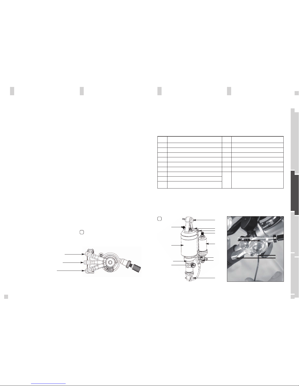
In the drawing of the shock and remote lever, shown
below, you will see the parts indicated with numbers
which will be used in the manual for the adjustment
and set-up. [2] [3]
GENIUS TC SHOCK AND
REMOTE CONTROL LEVER
02-03
1. ALL TRAVEL MODE: full travel of 125mm (Genius
MC) resp. 90mm (Genius RC / Genius Contessa).
2. TRACTION MODE: by reducing the air volume inside
the shock the travel of the shock will be reduced to
around 60%, the characteristic of the air spring gets
harder. This results in climbing without “bobbing” and
offers still optimum traction of the rear wheel.
3. LOCK OUT MODE: the shock is locked, climbing on
asphalt roads is now possible without any power loss.
Simultaneously a blow-off-system prevents the shock
being damaged in case the rider did not open the system
while crossing obstacles.
You will find following positions on the remote lever:
[1]
2 3
Genius Shock Remote Lever
S1 Upper Shock Bolt
S2 Lower Shock Bolt
S3 Piggy-Back
S4 Shock Housing
S5 Rebound-Screw
S6 Positive Chamber Valve
S7 Negative Chamber Valve
S8 Cable Fixation Screw
S9 Lock Out Lever
S10 Cable Clamping Screw
S11 Traction Mode Lever
S12 Shock Piston
L1 Remote Lever
L2 Remote Control Cable
L3 Tension Screw
L4 Allen Screw
S7
S1
S9
S8
S6
S3
S4
S12
S10
S11
S5
S2
L3
L4
L1
L2
1
Traction Control-Functions
Position lockout
Traction mode
All travel
ENGLISH
03
02
DEUTSCH
FRANÇAIS
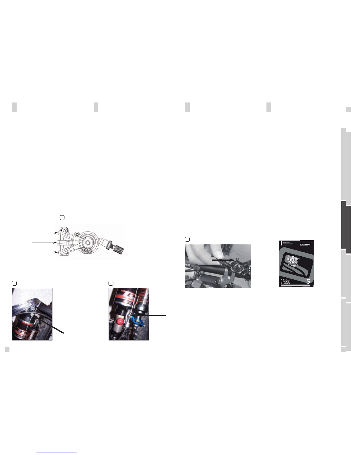
5.When putting now the remote lever to position “All
Travel” the cable will pull the traction mode lever downward and the shock will offer now the full travel. Check
now the set-up for perfect function of remote lever and
shock
6.In case you want to fine-tune the brake-away power
of the remote lever, you can do this by using a 2mm
allen key and by turning the allen screw (L4). In case
you want to readjust the tension of the remote control
cable you can do this by using the tension screw (L3).
[5]
1.Put the remote lever (L1) to position “lock-out”. [1]
2. Fix the remote control cable (L2) with the cable fixation
screw (S8) using a 3mm allen key (tightening torque:
3 Nm) on the lock out lever (S9). [3]
3.Put the remote lever now to position “Traction
Mode”. [1]
4.Fix the cable clamping screw (S10) using a 3mm allen
key (tightening torque 3Nm) on the traction mode lever
(S11). [4]
BASIC SET-UP OF THE REMOTE
CONTROL OF GENIUS TC SHOCK PLEASE NOTE
For the set-up of the shock we recommend to use
the tools listed below:
- a shock pump with a scale up to 20 bars/300 psi
with a special air valve connector preventing from
air getting away while removing the pump from
the shock valve and granting exact air pressure.
-Therefore we recommend the Scott Shock Pump
which you can order at your local Scott-Dealer
with parts number 15.1.834.208.0.000
- the SAG-Boy on the back of this manual
Please clean regularly after riding off-road the shock
piston (S12) and all other parts in motion of the shock
with a soft and wet cloth to prevent from excessive
wear and tear.
5
2 mm allen keg
ENGLISH
05
04
DEUTSCH
FRANÇAIS
RECOMMANDED TOOLS FOR
THE SHOCK SET-UP
3 4
Traction Control-Functions
Position lockout
Traction mode
All travel
1
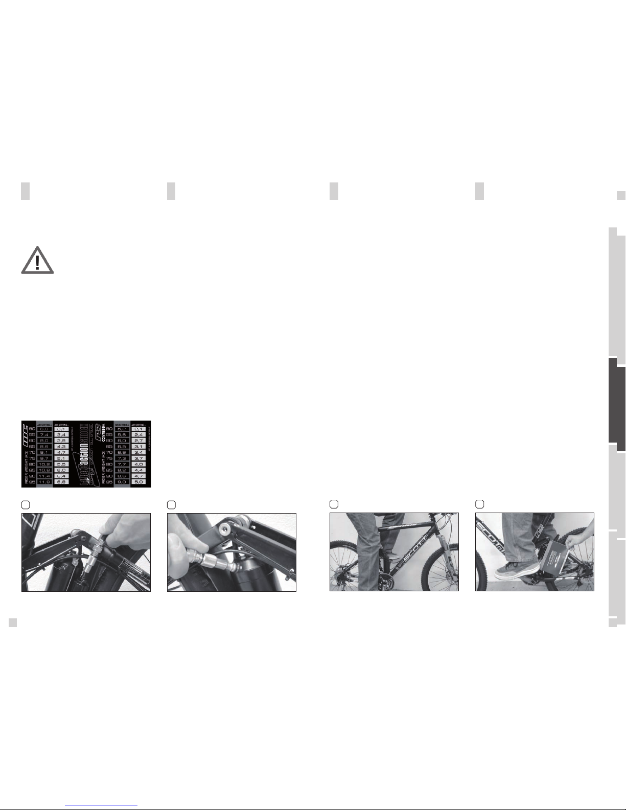
The SAG-Boy indicates the recommended eye-toeye distance of the shock bolts of the different
Genius models.
To check the adjustment, please follow as shown
below:
1. Sit on the bike, put your feet on the pedal. [9]
2. Ask a second person, to put the color beam of
the SAG-Boy, recommended for your bike model,
aside the eye-to-eye distance of the shock bolts.
3. If the distance between the bolts is corresponding to the length of the color beam, the air pressure is matching to your weight
4. If the distance between the bolts is shorter
than the length of the color beam, the air pressure
of the positive chamber is too high and should be
carefully reduced by using the bleed knob of the
shock pump until the measures are corresponding.
[10]
5. If the distance between the bolts is longer than
the length of the color beam, the air pressure of
the positive chamber is too low and should be
increased by using the shock pump until the measures are corresponding.
We recommend to make sure that the pressure balance
between positive and negative chamber follows the
recommendations shown on the piggy-back.
Not doing so may cause a loss in performance or comfort
or may result in damage of the shock.
After adjusting positive and negative chamber according
to the rider’s weight you can double check by using the
SAG-Boy, which is on the back of the manual, if the SAG
(negative travel) is well adjusted.
The negative travel is important when crossing grooves
or holes on the trail.
If the bike is well adjusted the rear wheel and the swingarm will roll through the groove without the mainframe
moving.
The SAG should be 15-20% of the travel for race oriented
riders and 20-25% of the travel for comfort oriented
riders.
109
SET-UP OF NEGATIVE AIR
CHAMBER GENIUS TC SHOCK
SET-UP OF POSITIVE AIR
CHAMBER GENIUS TC SHOCK
The negative air chamber contains the air-spring
influencing the brake-away and characteristic while
absorbing shocks. A too high brake-away can cause
an non-secure and uncomfortable ride. [8]
To adjust the air pressure of the negative chamber of the
Scott Genius Shock please refer to the following instruction:
1. Remove the cap of the silver valve (S7) located on the
shock housing (S4).
2. Mount the shock pump with its adaptor on the valve.
3. Pump the recommended pressure into the shock housing. On the housing of the piggy-back you will find a
table showing in the silver colored areas the recommended air pressure of the negative chamber according
to the rider’s weight.
4. When you reached the needed pressure remove the
pump and put the valve cap on the valve.
The positive air chamber contains the air-spring you
“sit-on” while riding. [7]
To adjust the air pressure of the positive chamber of
the Scott Genius Shock please refer to the following
instruction:
1. Remove the valve cap of the black valve (S6) located
on the Piggy-Back (S3).
2. Mount the shock pump with its adaptor on the valve
3. Pump the recommended pressure into the Piggy-Back.
On the housing of the Piggy-Back you will find a table
showing in the black colored areas the recommended
air pressure of the positive chamber according to the
rider’s weight.
4. When you reached the needed pressure remove the
pump and put the valve cap on the valve.
7 8
Positive Air Chamber Negative Air Chamber
ENGLISH
07
06
DEUTSCH
FRANÇAIS
IMPORTANT:
For all adjustments of the air spring
the lockout lever has to be in position
“all travel”.
 Loading...