

Scott Road,Cyclo-Cross,Time Trial Machine Owner's Manual

EN ISO 4210-2
SCOTT OWNER’S MANUAL
ROAD BIKE
WWW.SCOTT-SPORTS.COM

Read at least pages 10-18 before your first ride!
Perform the functional check on pages 19-21 before every ride!
WWW.SCOTT-SPORTS.COM
Read this SCOTT owner’s manual and the manuals of the component manufacturers on this SCOTT info CD! Together with the manuals of the component
manufacturers this SCOTT owner’s manual is part of a system.
If this SCOTT owner’s manual will not deliver the responses to all questions and
before changing any settings, ask your SCOTT dealer.
Observe the chapter “Intended use of your SCOTT bike”, the SCOTT
service plan, the SCOTT bike card and the SCOTT handover report!
Your bike and this owner’s manual comply
with the requirements of the EN ISO standard
4210-2 Cycles – Safety requirements for bicycles.
DANG ER!
Register your SCOTT bike on www.scott-sports.com within 10 days as of
g
the date of purchase. Your references may particularly help ensure your
safety, as we can inform you about possible measures to be taken, if necessary.
CAUTION!
It is essential to also observe the manuals of the component manufacturers
A
on this SCOTT info CD. The present owner’s manual is subject to European
law and the EN/ISO standards. If delivered to countries outside Europe, supplementary information has to be provided by the importer of the SCOTT bike, if
necessary.
NOTE!
Inform yourself on www.scott-sports.com
I
Imprint:
V 6.1, January 2017
Technical details in the text and illustrations of this manual are subject to
change.
© No part of this publication may be reprinted, translated, copied or transmitted
in any form or by any means, electronic, mechanical, by hand or otherwise for
another business purpose without prior written permission of Zedler – Institut
für Fahrradtechnik und -Sicherheit GmbH.
| 02
ENGLISH
© Text, concept, photos and graphic design
Zedler – Institut für Fahrradtechnik und -Sicherheit GmbH www.zedler.de and
SCOTT-SPORTS SA www.scott-sports.com
ROAD BI KE | OWNER’S MANUAL 2017OWNER’S MANUAL 2017 | ROAD BIKE
ENGLISH
03 |
SCOTT ROAD BIKE SCOTT CYCLO-CROSS BIKE
1
2
3
4
5
6
7
8
4
9
10
11
SCOTT TIME TRIAL MACHINE
1
2
6
7
8
9
10
11
5
4
13
14
20
1
6
21
22
3
2
24
1
2
3
5
1
3
2
6
6
25
26
27
4
5
7
8
4
28
29
9
10
13
14
20
21
24
22
23
25
26
27
28
29
11
12
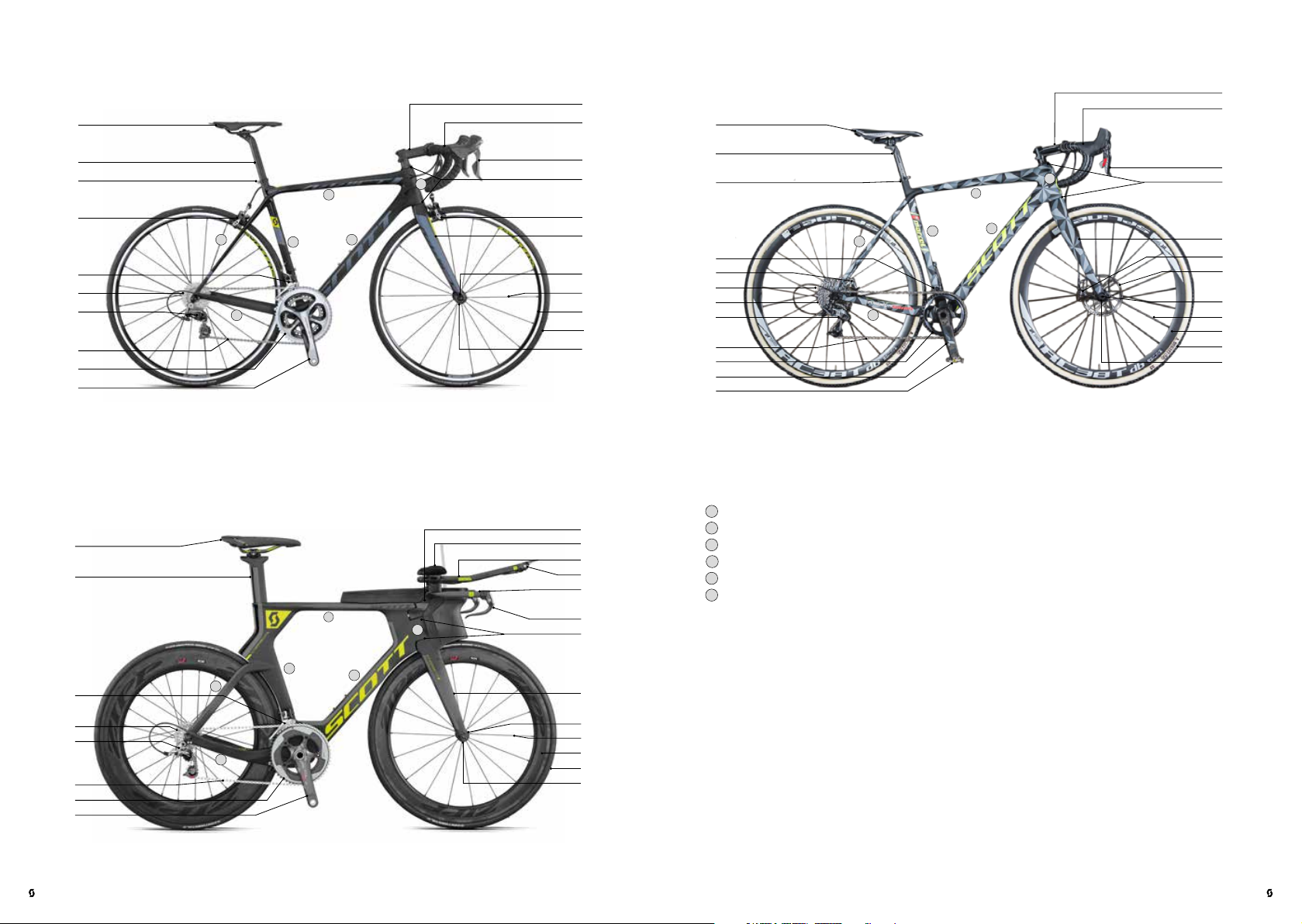
Frame:
1
Top t u b e
2
13
15
16
19
17
1
6
18
21
Down tube
3
Seat tube
4
Chainstay
5
Rear stay
6
Head tube
1 Saddle
2 Seat post
3 Seat post clamp
4 Rear brake
5 Rotor
6 Front derailleur
7 Cassette sprockets
8 Rear derailleur
17 Bull-horn handlebars
18 Brake lever
19 Shifter
20 Brake lever/shifter
21 Headset
22 Front brake
23 Rotor
24 Fork
9 Chain
3
2
24
25
26
27
28
10 Chainwheel
11 Crank
12 Pedal
13 Stem
14 Handlebar
15 Armrests
16 Extensions
29
Wheel:
25 Quick-release/
thru axle
26 Spoke
27 Rim
28 Tyr e
29 Hub
| 04
ENGLISH
ROAD BI KE | OWNER’S MANUAL 2017OWNER’S MANUAL 2017 | ROAD BIKE
ENGLISH
05 |

TABLE OF CONTENTS
SOME NOTES ON THIS SCOTT OWNER’S MANUAL . . . . . . . . . . . . . . .09
SAFETY AND BEHAVIOUR . . . . . . . . . . . . . . . . . . . . . . . . . . . . . . . . 10
INTENDED USE OF YOUR SCOTT BIKE . . . . . . . . . . . . . . . . . . . . . . . . 13
TESTS BEFORE YOUR FIRST RIDE . . . . . . . . . . . . . . . . . . . . . . . . . . . 16
TESTS BEFORE EVERY RIDE . . . . . . . . . . . . . . . . . . . . . . . . . . . . . . . 19
USING QUICK-RELEASES AND THRU AXLES . . . . . . . . . . . . . . . . . . . . 21
Quick-releases on the SCOTT bike . . . . . . . . . . . . . . . . . . . . . . . . . . . . 21
Safe fastening of a component with a quick-release . . . . . . . . . . . . . . . . . . . .22
Thru axles on the SCOTT bike . . . . . . . . . . . . . . . . . . . . . . . . . . . . . . .26
Safe fastening of components with a quick-release . . . . . . . . . . . . . . . . . . . . 26
ADJUSTING THE SCOTT BIKE TO THE RIDER . . . . . . . . . . . . . . . . . . .28
Adjustment of the saddle to the correct height. . . . . . . . . . . . . . . . . . . .29
Adjustment of the height of the handlebars . . . . . . . . . . . . . . . . . . . . . .31
Stems for threadless systems – Aheadset® . . . . . . . . . . . . . . . . . . . . . . . . . 33
What to bear in mind with SCOTT bikes with carbon steerer . . . . . . . . . . . . . . .34
Saddle adjustment – fore-to-aft position and horizontal tilt . . . . . . . . . . . .36
Adjustment of saddle position and tilt. . . . . . . . . . . . . . . . . . . . . . . . . . . .37
Cockpit adjustment . . . . . . . . . . . . . . . . . . . . . . . . . . . . . . . . . . . . .40
Brake lever reach adjustment on SCOTT road bikes and SCOTT cyclo-cross bikes . . .40
Adjustment of handlebar tilt and brake lever/shifter units on SCOTT road bikes
and SCOTT cyclo-cross bikes . . . . . . . . . . . . . . . . . . . . . . . . . . . . . . . . 42
What to bear in mind with aero bars on SCOTT triathlon bikes and
SCOTT time trial machines . . . . . . . . . . . . . . . . . . . . . . . . . . . . . . . . . .43
BRAKES . . . . . . . . . . . . . . . . . . . . . . . . . . . . . . . . . . . . . . . . . . . . .44
Rim brakes . . . . . . . . . . . . . . . . . . . . . . . . . . . . . . . . . . . . . . . . . . .46
Racing and side-pull brakes . . . . . . . . . . . . . . . . . . . . . . . . . . . . . . . . .46
Cross/Cantilever brakes . . . . . . . . . . . . . . . . . . . . . . . . . . . . . . . . . . .48
Disc Brakes . . . . . . . . . . . . . . . . . . . . . . . . . . . . . . . . . . . . . . . . . . 51
Hydraulic disc brakes . . . . . . . . . . . . . . . . . . . . . . . . . . . . . . . . . . . . . 52
Mechanical disc brakes . . . . . . . . . . . . . . . . . . . . . . . . . . . . . . . . . . . . 54
GEARS . . . . . . . . . . . . . . . . . . . . . . . . . . . . . . . . . . . . . . . . . . . . . .55
Derailleur gears. . . . . . . . . . . . . . . . . . . . . . . . . . . . . . . . . . . . . . . .55
Operation and control . . . . . . . . . . . . . . . . . . . . . . . . . . . . . . . . . . . . 56
Checking and readjusting . . . . . . . . . . . . . . . . . . . . . . . . . . . . . . . . . . 59
Adjusting the rear derailleur . . . . . . . . . . . . . . . . . . . . . . . . . . . . . . . . .60
Adjusting the front derailleur. . . . . . . . . . . . . . . . . . . . . . . . . . . . . . . . .62
Shimano Di2 . . . . . . . . . . . . . . . . . . . . . . . . . . . . . . . . . . . . . . . . . .63
Rechargeable battery. . . . . . . . . . . . . . . . . . . . . . . . . . . . . . . . . . . . .64
BICYCLE CHAIN. . . . . . . . . . . . . . . . . . . . . . . . . . . . . . . . . . . . . . . .66
Chain maintenance . . . . . . . . . . . . . . . . . . . . . . . . . . . . . . . . . . . . .66
WHEELS AND TYRES . . . . . . . . . . . . . . . . . . . . . . . . . . . . . . . . . . . .67
Notes on tyres, inner tubes, rim tape, inflation pressure . . . . . . . . . . . . . . 68
Valves . . . . . . . . . . . . . . . . . . . . . . . . . . . . . . . . . . . . . . . . . . . . . .70
Rim trueness and spoke tension . . . . . . . . . . . . . . . . . . . . . . . . . . . . . 71
Carbon wheels . . . . . . . . . . . . . . . . . . . . . . . . . . . . . . . . . . . . . . . . 71
Particularities of braking with carbon wheels . . . . . . . . . . . . . . . . . . . . . . . .72
REPAIRING TYRE PUNCTURES . . . . . . . . . . . . . . . . . . . . . . . . . . . . . 73
Removing the wheel. . . . . . . . . . . . . . . . . . . . . . . . . . . . . . . . . . . . .74
Clincher and folding tyres . . . . . . . . . . . . . . . . . . . . . . . . . . . . . . . . . 75
Tyre removal. . . . . . . . . . . . . . . . . . . . . . . . . . . . . . . . . . . . . . . . . .75
Tyre mount i ng . . . . . . . . . . . . . . . . . . . . . . . . . . . . . . . . . . . . . . . . .76
TUBULAR TYRES . . . . . . . . . . . . . . . . . . . . . . . . . . . . . . . . . . . . . . 78
Tyre removal. . . . . . . . . . . . . . . . . . . . . . . . . . . . . . . . . . . . . . . . . .79
Tyre mount i ng . . . . . . . . . . . . . . . . . . . . . . . . . . . . . . . . . . . . . . . . .80
Remounting the wheel . . . . . . . . . . . . . . . . . . . . . . . . . . . . . . . . . . .84
TESTS AFTER AN ACCIDENT. . . . . . . . . . . . . . . . . . . . . . . . . . . . . . .86
CARBON – A PARTICULAR MATERIAL . . . . . . . . . . . . . . . . . . . . . . . . 88
THE HEADSET ON THE SCOTT BIKE . . . . . . . . . . . . . . . . . . . . . . . . . . 91
Checking and readjusting . . . . . . . . . . . . . . . . . . . . . . . . . . . . . . . . . . 91
Threadless headset – Aheadset® . . . . . . . . . . . . . . . . . . . . . . . . . . . . . 92
LIGHTING OF YOUR SCOTT BIKE . . . . . . . . . . . . . . . . . . . . . . . . . . . .93
Battery-operated lighting . . . . . . . . . . . . . . . . . . . . . . . . . . . . . . . . .94
USEFUL FACTS ABOUT THE SCOTT BIKE . . . . . . . . . . . . . . . . . . . . . .94
Helmets and glasses. . . . . . . . . . . . . . . . . . . . . . . . . . . . . . . . . . . . .94
Clothing . . . . . . . . . . . . . . . . . . . . . . . . . . . . . . . . . . . . . . . . . . . . 95
Pedals and shoes. . . . . . . . . . . . . . . . . . . . . . . . . . . . . . . . . . . . . . .96
Accessories . . . . . . . . . . . . . . . . . . . . . . . . . . . . . . . . . . . . . . . . . . 97
Bicycle locks. . . . . . . . . . . . . . . . . . . . . . . . . . . . . . . . . . . . . . . . . .98
Puncture kit . . . . . . . . . . . . . . . . . . . . . . . . . . . . . . . . . . . . . . . . . .98
| 06
ENGLISH
ROAD BI KE | OWNER’S MANUAL 2017OWNER’S MANUAL 2017 | ROAD BIKE
ENGLISH
07 |
Cycle computers . . . . . . . . . . . . . . . . . . . . . . . . . . . . . . . . . . . . . . . 99
Aero or triathlon/time trial bars . . . . . . . . . . . . . . . . . . . . . . . . . . . . . . . 99
Mudguards (wheel protections) . . . . . . . . . . . . . . . . . . . . . . . . . . . . . . . 99
SCOTT-Rucksack . . . . . . . . . . . . . . . . . . . . . . . . . . . . . . . . . . . . . . 100
Transporting luggage . . . . . . . . . . . . . . . . . . . . . . . . . . . . . . . . . . .100
Taking children with you . . . . . . . . . . . . . . . . . . . . . . . . . . . . . . . . . 100
TRANSPORT OF THE SCOTT BIKE . . . . . . . . . . . . . . . . . . . . . . . . . . .101
By car . . . . . . . . . . . . . . . . . . . . . . . . . . . . . . . . . . . . . . . . . . . . . .101
By train / By public transport . . . . . . . . . . . . . . . . . . . . . . . . . . . . . . 103
By plane . . . . . . . . . . . . . . . . . . . . . . . . . . . . . . . . . . . . . . . . . . . 103
GENERAL NOTES ON CARE AND SERVICING . . . . . . . . . . . . . . . . . . 104
Maintenance and servicing your SCOTT bike . . . . . . . . . . . . . . . . . . . . 104
Cleaning and caring for your SCOTT bike . . . . . . . . . . . . . . . . . . . . . . 105
Sheltering and storing your SCOTT bike . . . . . . . . . . . . . . . . . . . . . . . 107
SCOTT SERVICE AND MAINTENANCE SCHEDULE . . . . . . . . . . . . . . . 108
RECOMMENDED TORQUE SETTINGS FOR YOUR SCOTT BIKE. . . . . . . .110
Recommended torque settings for disc brakes on your SCOTT bike . . . . . .112
LEGAL REQUIREMENTS FOR RIDING ON PUBLIC ROADS . . . . . . . . . . .113
WARRANTY AND GUARANTEE . . . . . . . . . . . . . . . . . . . . . . . . . . . . .114
Notes on wearing parts . . . . . . . . . . . . . . . . . . . . . . . . . . . . . . . . . . .115
GUARANTEE ON SCOTT BIKES . . . . . . . . . . . . . . . . . . . . . . . . . . . . .116
SERVICE PLAN . . . . . . . . . . . . . . . . . . . . . . . . . . . . .118
BIKE CARD . . . . . . . . . . . . . . . . . . . . . . . . . . . . . . 124
HANDOVER REPORT. . . . . . . . . . . . . . . . . . . . . . . . 125
SOME NOTES ON THIS SCOTT OWNER’S MANUAL
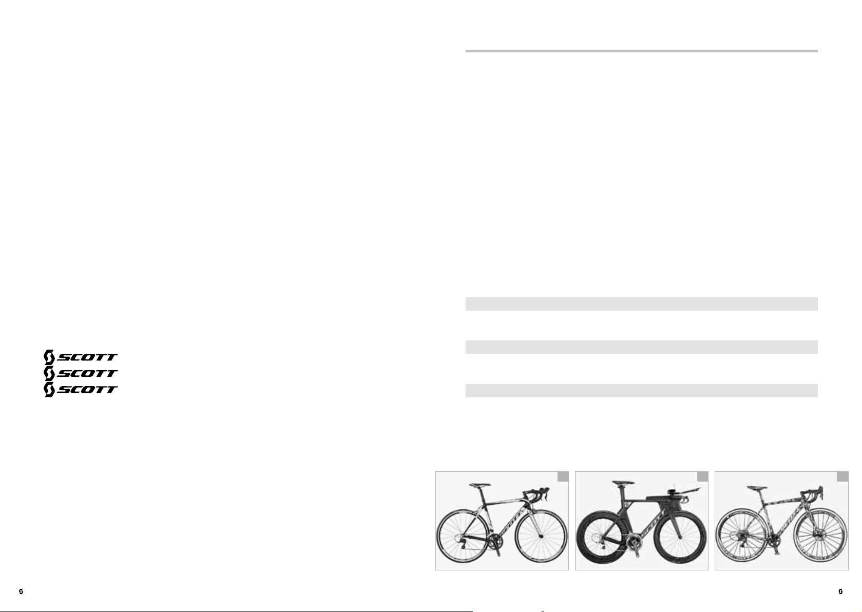
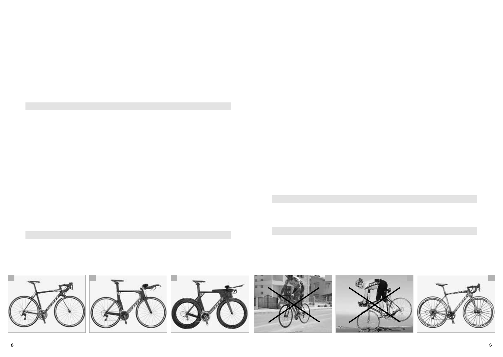
The illustrations on the first pages of the SCOTT owner’s manual show a typical
SCOTT road bike, a SCOTT time trial machine and a typical SCOTT cyclo-cross
bike. One of these SCOTT bikes looks similar to the SCOTT bike you have purchased. Today’s bikes come in various types that are designed for specific uses
and fitted accordingly. The present SCOTT owner’s manual includes the following bicycle types:
Road bikes (d)
Triathlon bikes
Time trial machines (e)
Cyclo-cross bikes (f)
This SCOTT owner’s manual is not applicable to any other than the displayed
bicycle types. This manual is not intended to help you assemble a SCOTT bike
from individual components, to repair it or to make a partly assembled SCOTT
bike ready for use.
In this SCOTT owner’s manual the term “road bike” will always be used in
general descriptions if it refers to road and triathlon bikes as well as time trial
machines and cyclo-cross bikes.
Pay particular attention to the following symbols:
DANG ER!
This symbol indicates an imminent risk to your life or health unless you
G
comply with the instructions given or take preventive measures.
CAUTION!
This symbol warns you of wrongdoings which may result in damage to
A
property and the environment.
NOTE!
This symbol provides you with information about how to handle the prod-
I
uct or refers to a passage in the SCOTT owner’s manual that deserves your
special attention.
| 08
e fd
ROAD BI KE | OWNER’S MANUAL 2017OWNER’S MANUAL 2017 | ROAD BIKE
ENGLISHENGLISH
09 |
The described possible consequences will not be repeated in the SCOTT owner’s manual every time one of the symbols appears.
The present SCOTT owner’s manual together with this SCOTT info CD complies
with the requirements of the EN ISO standard 4210-2 road bikes.
It is essential to also observe the manuals of the component manufacturers on
this SCOTT info CD.
Therefore, before setting off on your new SCOTT bike, you should read at least
the chapter “Tests before your first ride”. To ensure as much fun and safety as
possible during cycling, be sure to carry out the functional check described in
the chapter “Tests before every ride” before setting off on your SCOTT bike.
Even a manual as detailed as an encyclopaedia could not describe every possible combination of available bicycle models and components. This SCOTT
owner’s manual therefore focuses on your newly purchased SCOTT bike and
standard components (c) and provides useful information and warnings for the
handling of your new SCOTT bike.
SAFETY AND BEHAVIOUR
Dear SCOTT customer,
Congratulations on your purchase of a new SCOTT bike. We are confident that
the bike will exceed your expectations for quality, functioning and riding characteristics. Our SCOTT frames and components are customized and adjusted to
suit the needs of the users to enhance your joy when riding on your new SCOTT
bike – whether you are a beginner or a non-professional road racer!
To ensure that you ride safely and with joy, we strongly encourage you to take
the time to read this SCOTT owner’s manual thoroughly.
In purchasing this SCOTT bike you have chosen a product of high quality and
technology. Each component of your new SCOTT bike has been designed,
manufactured and assembled with great care and expertise. Your SCOTT dealer
gave the bike its final assembly and made a functional check. This guarantees
you pleasure and a sense of confidence from the very first turn of the pedals
(a+b).
This SCOTT owner’s manual contains a wealth of useful facts on the proper
use of your SCOTT bike, its maintenance and operation as well as interesting
information on bike design and engineering. Read this SCOTT owner’s manual
thoroughly. We are sure that even if you have been cycling for many years you
will find it worthwhile. Bike technology has developed at a rapid pace during
recent years.
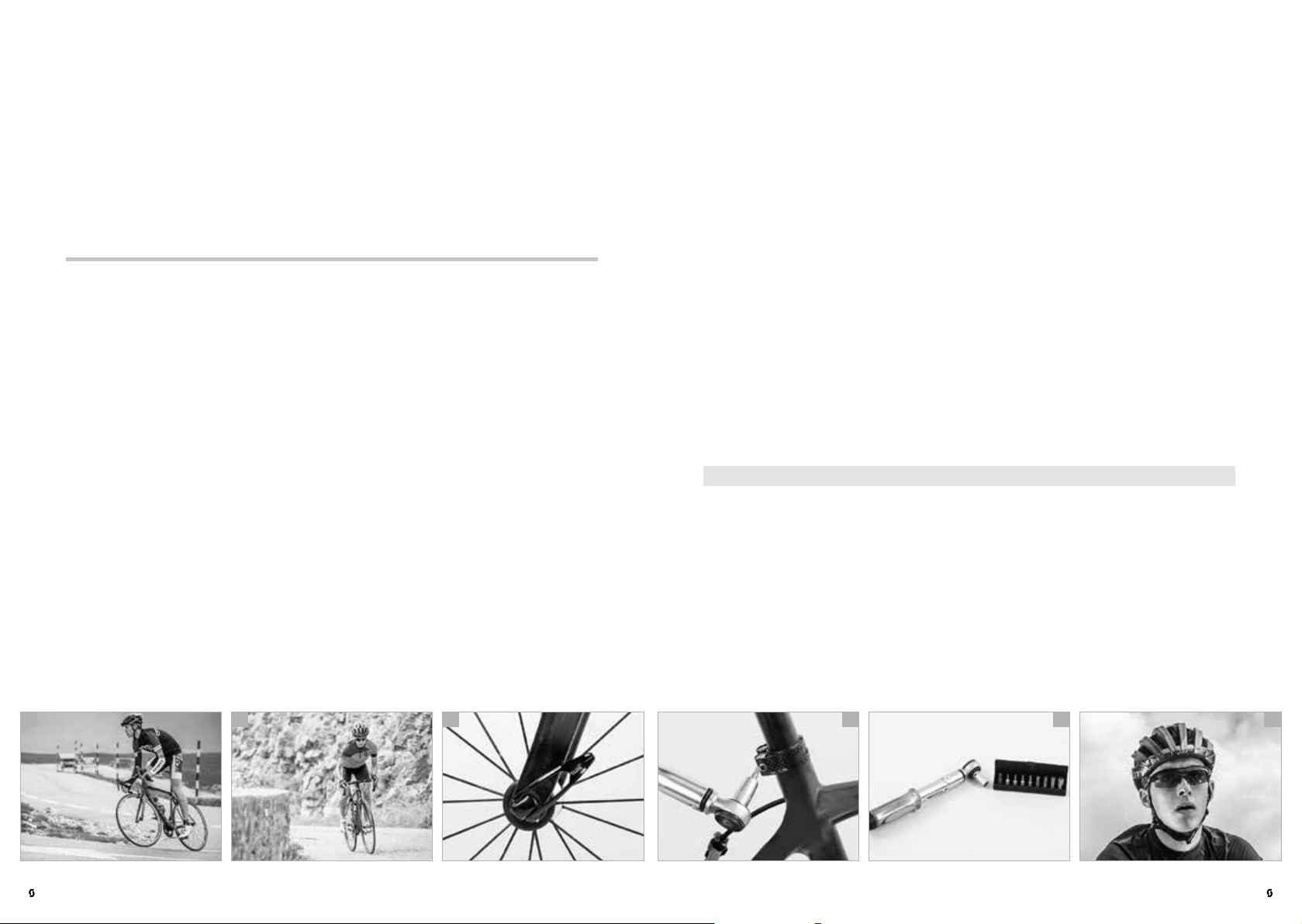
When doing any adjusting and servicing (d), be aware that the detailed instructions provided in your manual only refer to this SCOTT bike.
The information included here is not applicable to any other bicycle type. As
bicycles come in a wide variety of designs with frequent model changes, the
routines described may require complementary information. It is essential to also
observe the manuals of the component manufacturers on this SCOTT info CD.
Be aware that these instructions may require further explanation, depending on
the experience and/or skills of the person doing the work. For some jobs you
may require additional (special) tools (e) or supplementary instructions.
This manual cannot teach you the skills of a bicycle mechanic.
NOTE!
This SCOTT info CD includes the manuals of the component manufacturers
I
as well as the relevant web links.
Before you set off, let us point out a few things to you that are very important to
every cyclist: Never ride without a properly adjusted helmet and without glasses
(f). Make sure to wear suitable, bright clothing. As a minimum you should wear
straight cut trousers or leg bands and shoes fitting the pedal system.
Always ride carefully on public roads and observe the traffic rules so as not to
endanger yourself or others.
| 10
b ca e fd
ROAD BI KE | OWNER’S MANUAL 2017OWNER’S MANUAL 2017 | ROAD BIKE
ENGLISHENGLISH
11 |
1
2
3
6
4
5
7
8
9
10
11
12
ENGLISH
SCOTT ROAD BIKE
13
14
20
21
22
24
25
26
27
28
29
1
2
3
4
5
6
1
2
3
4
6
7
8
9
10
11
1
2
3
6
4
5
7
8
9
10
11
12
This manual cannot teach you how to ride. Please be aware that cycling is a
potentially dangerous activity that requires the rider to stay in control of his or
her SCOTT bike at all times. If necessary, attend a beginners course for cyclists,
as offered here and there.
DANG ER!
For your own safety, never do any work or adjusting (f) when servicing your
G
bike (e) unless you feel absolutely sure about it. If you are in doubt or if you
have any questions, contact your SCOTT dealer.
Like any sport, cycling involves the risk of injury and damage. By choosing to
ride a bike, you assume the responsibility for the risk. Please note that on a bike
you have no protection technique around you like you have in a car (e.g. bodywork, ABS, airbag). Therefore, always ride carefully and respect the other traffic
participants.
Never ride under the influence of drugs, medication, alcohol or when you are
tired. Do not ride with a second person on your SCOTT bike and never ride without having both hands on the handlebars.
Observe the legal regulations concerning cycling with SCOTT bikes on public
roads. These regulations may differ in each country.
Respect nature when riding through the forest and in the open countryside.
Only use your SCOTT bike on signposted, well maintained trails and hard-surface roads with a smooth surface (a).
First, we would like to familiarize you with the various components of your
SCOTT bike. Please unfold the cover of the SCOTT owner’s manual. There you
will find a SCOTT road bike (b), a SCOTT time trial machine (c) and a typical
SCOTT cyclo-cross bike (d) showing all the essential components. Leave the
page unfolded as you read so that you can easily locate the components as they
are referred to in the text.
DANG ER!
Note: Do not hitch yourself and your bike to a car. Do not ride freehand.
G
Only take your feet off the pedals, if required by the condition of the road.
SCOTT – NO SHORTCUTS
INTENDED USE OF YOUR SCOTT BIKE
Your SCOTT bike was designed by our engineers for a specific use. Be sure to
use your SCOTT bike only according to its intended use, as it may otherwise not
withstand the stress and could fail and cause an accident with unforeseeable
consequences! Any use contrary to the intended purpose will render the warranty null and void.
NOTE!
Inform yourself at www.scott-sports.com to which category your new
I
SCOTT bike belongs.
There is no bicycle type which is suitable for all purposes. Your SCOTT dealer
will be pleased to help you finding the right SCOTT bike for your needs. He will
also explain you the limits of the different types of bicycle.
| 12
b ca e fd
SCOTT ROAD BIKE
1
2
3
4
6
7
8
9
10
11
6
1
5
2
3
4
SCOTT TIME TRIAL MACHINE
13
1
14
2
20
21
22
24
6
25
7
26
8
27
28
9
29
10
11
SCOTT CYCLO-CROSS BIKE
13
15
16
1
19
17
1
6
3
5
2
4
2
18
3
21
24
6
4
25
5
26
7
27
8
28
29
9
10
11
12
3
5
4
ROAD BI KE | OWNER’S MANUAL 2017OWNER’S MANUAL 2017 | ROAD BIKE
13
14
6
1
2
20
21
24
22
23
25
26
27
28
29
ENGLISHENGLISH
13 |
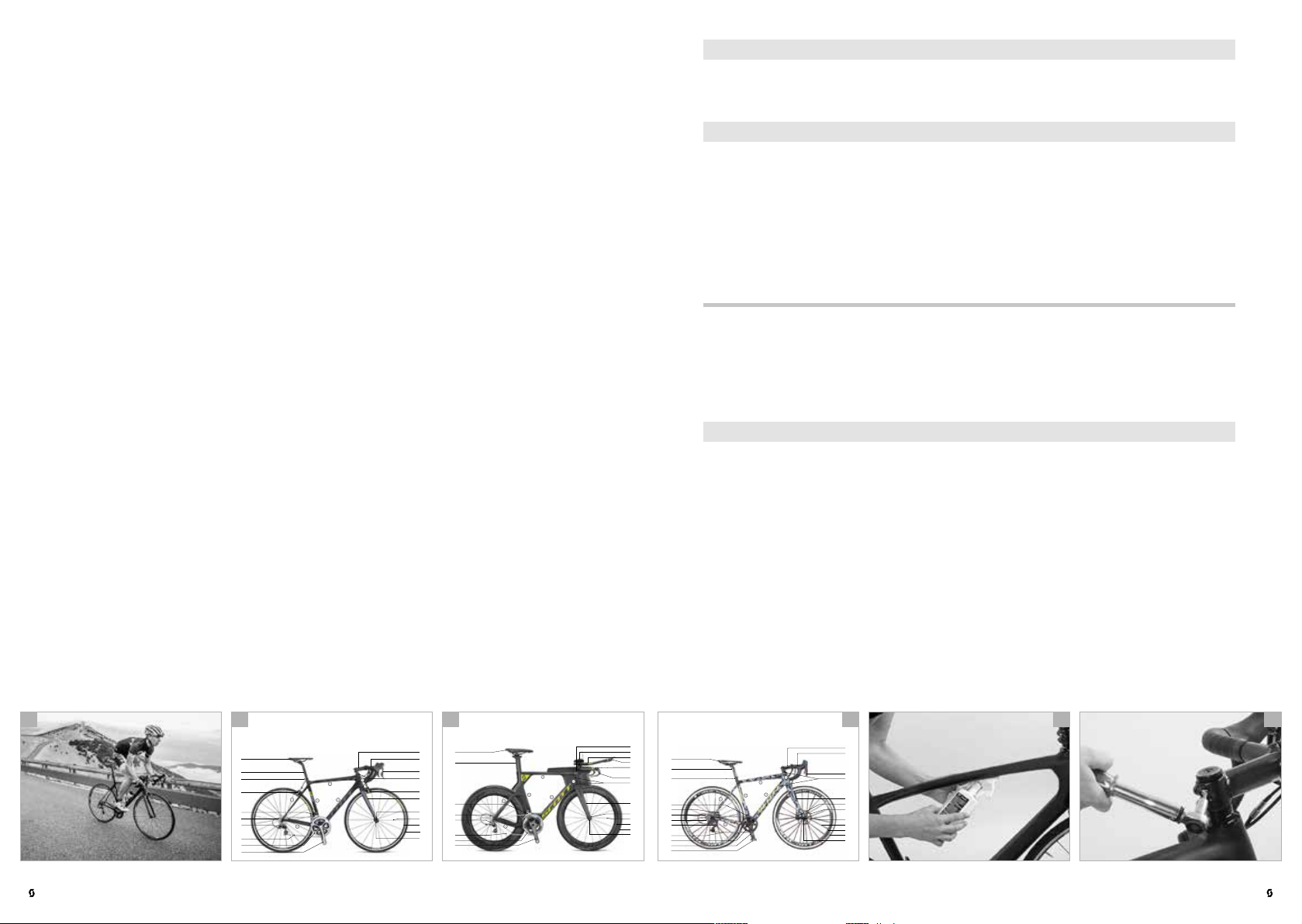
Category 1: SCOTT road and triathlon bikes as well as time trial machines
If you want to use SCOTT road bikes (a), triathlon bikes (b) as well as time trial
machines (c) on public roads, these bikes must be fitted with the prescribed
equipment.
Observe the traffic rules when riding on public roads. For more information see
the chapter “Legal requirements for riding on public roads“.
For SCOTT road and triathlon bikes as well as time trial machines trailers, child
carriers and pannier racks are not permitted. Note that SCOTT will not assume
liability for the use of trailers, child carriers and pannier racks. Such a use would
render the warranty null and void.
DANG ER!
SCOTT bikes of the category 1 are not suitable for off-road use, jumps (d),
G
slides, stair riding, stoppies (e), wheelies, tricks etc.!
SCOTT road and triathlon bikes as well as time trial machines are exclusively
designed for riding on hard-surface paths and roads with tarred or paved surface. The tyres must remain in constant contact with the ground.
These bicycles are not suitable for off-road and cyclo-cross use or for touring
with pannier racks and bags.
SCOTT Bikes Aero, Lightweight, Endurance Comfort and Contessa Road belong
to this category.
Category 2.3: SCOTT cyclo-cross bikes
Due to their design and fittings, SCOTT cyclo-cross bikes (f) are not always
suitable for being used on public roads. If you want to use them on public roads,
these bikes must be fitted with the prescribed equipment. Observe the traffic
rules when riding on public roads. For more information see the chapter “Legal
requirements for riding on public roads“.
SCOTT cyclo-cross bikes - CX are designed for riding on hard-surface terrain,
i.e. on tarred roads and bicycle lanes or gravel and grass field tracks. The tyres
must remain in constant contact with the ground. In addition, they are well
suited for well paved gravel paths and forest roads as well as off-road trails with
a slight slope where a temporary loss of tyre contact with the ground due to
small steps may occur. In addition, they are suitable for use on easy terrain and
in cyclo-cross competitions.
These bicycles are not suitable for off-road use, such as mountain bike use,
namely all mountain, enduro, downhill (DH), freeride, dual slalom, downhill/freeride parks, jumps, drops and in bike parks etc.
SCOTT bikes CX belong to this category.
The permissible overall weight (rider incl. luggage and bicycle) must not ex-
ceed 117 to 120 kg / 315 to 330 lbs (according to model). Under certain circum-
stances the permissible maximum weight can be further limited by the component manufacturers’ recommendations for use.
For SCOTT cyclo-cross bikes trailers, child carriers and pannier racks are not
permitted. Note that SCOTT will not assume liability for the use of trailers, child
carriers and pannier racks. Such a use would render the warranty null and void.
The permissible overall weight (rider incl. luggage and bicycle) must not ex-
ceed 117 to 120 kg / 315 to 330 lbs (according to model). Under certain circum-
stances the permissible maximum weight can be further limited by the component manufacturers’ recommendations for use.
NOTE!
Inform yourself at www.scott-sports.com to which category your new
I
SCOTT bike belongs.
b ca e fd
| 14
DANG ER!
SCOTT bikes of the category 2.3 are not suitable for riding over challenging
G
and blocked terrain, jumps, slides, stair riding, stoppies, wheelies, tricks
etc.!
NOTE!
Inform yourself at www.scott-sports.com to which category your new
I
SCOTT bike belongs.
ROAD BI KE | OWNER’S MANUAL 2017OWNER’S MANUAL 2017 | ROAD BIKE
ENGLISHENGLISH
15 |

TESTS BEFORE YOUR FIRST RIDE
1. If you want to use your bike on public roads, it has to comply with legal
requirements. These requirements may vary in each country. The fittings of
your SCOTT bike are, therefore, not necessarily complete (a).
Ask your SCOTT dealer concerning the laws and regulations applicable in
your country or in the country you intend to use your SCOTT bike. Have your
SCOTT bike equipped accordingly before using it on public roads.
For more information see the chapter “Legal requirements for riding on pub-
lic roads“.
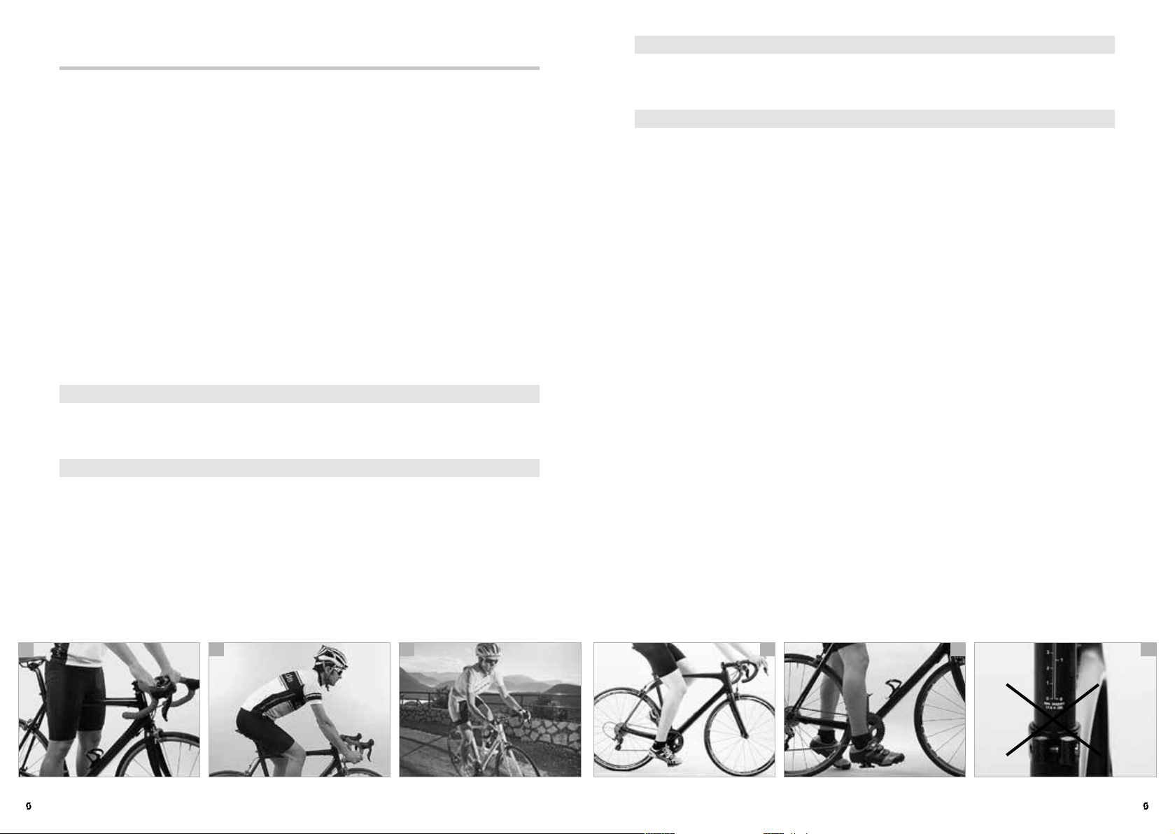
4. Are saddle and handlebars properly adjusted? The saddle should be set to
a height from which you can just reach the pedal in its lowest position with
your heel (d). The hips should remain horizontal. Check whether your toes
reach to the floor when you are sitting on the saddle. Your SCOTT dealer will
be pleased to help you, if you are not happy with your seating position.
For more information see the chapter “Adjusting the SCOTT bike to the rider”.
5. If your SCOTT bike is equipped with clipless or step-in pedals (e): Have you
ever tried cycling with the respective cycling shoes? First practise locking
one shoe onto a pedal and disengaging it while standing on the other leg.
Ask your SCOTT dealer to explain you the pedals and to adjust them to your
needs.
2. Are you familiar with the brake system (b)? Have a look at the SCOTT bike
card and check whether the brake lever of the front brake is on the side you
are used to (right or left). If it is not, ask your SCOTT dealer to switch the
brake levers before you set off for the first time.
Your new bike is equipped with modern brakes which may be far more pow-
erful than those you were used to so far. Be sure to first practise using the
brakes on a level, non-slip surface off public roads! Slowly approach higher
brake performances and speeds.
For more information see the chapter “Brakes” and the manuals of the com-
ponent manufacturers on this SCOTT info CD.
3. Are you familiar with the type and functioning of the gears (c)? Ask your
SCOTT dealer to explain you the gear system and make yourself familiar with
your new gears in an area free of traffic, if necessary.
For more information see the chapter “Gears” and the manuals of the com-
ponent manufacturers on this SCOTT info CD.
b ca e fd
For more information see the chapter “Pedals and shoes” and the manuals of
the component manufacturers on this SCOTT info CD.
DANG ER!
Be aware that the distance you need to stop your bike increases, when
G
you are riding with your hands on aero bars or on triathlon bars. The brake
levers are not always within easy reach.
DANG ER!
Be sure to use your SCOTT bike only for its intended purpose, as it may
G
otherwise not withstand the stress and fail. Risk of falling!
DANG ER!
Make particularly sure there is enough space between your crotch and the
G
top tube (f) so that you do not hurt yourself, if you have to get off your
bicycle quickly.
DANG ER!
Note that both braking effect and tyre grip can be reduced drastically in
G
wet conditions. Look well ahead when riding on wet roads and go well
below the speed you would ride at in dry conditions.
| 16
ROAD BI KE | OWNER’S MANUAL 2017OWNER’S MANUAL 2017 | ROAD BIKE
ENGLISHENGLISH
17 |
DANG ER!
A lack of practice when using clipless pedals or too much spring tension in
G
the mechanism can lead to a very firm connection, from which you cannot
quickly step out! Risk of falling!
DANG ER!
In case you had a crash with your SCOTT bike, perform at least the check
G
described in the chapters “Tests before every ride“ and “Tests after an
accident“. Only ride back very carefully on your SCOTT bike, if it passed the
tests without any problems. Do not accelerate or brake hard and do not ride
your bike out of the saddle. If you are in doubt, have yourself picked up by car,
instead of taking any risk. Back home you need to check your SCOTT bike thoroughly once again. If you are in doubt or if you have any questions, contact your
SCOTT dealer!
TESTS BEFORE EVERY RIDE
Your SCOTT bike has undergone numerous tests during production and a final
check has been carried out by your SCOTT dealer. Nevertheless, be sure to
check the following points to exclude any malfunctioning that may be due to
the transport of your SCOTT bike or to changes a third person may have performed on your SCOTT bike before delivery:
1. Are the quick-release levers (c), thru axles or nuts of the front and rear wheel,
the seat post (d) and other components properly closed?
For more information see the chapter “Using quick-releases and thru axles”
and the manuals of the component manufacturers on this SCOTT info CD.
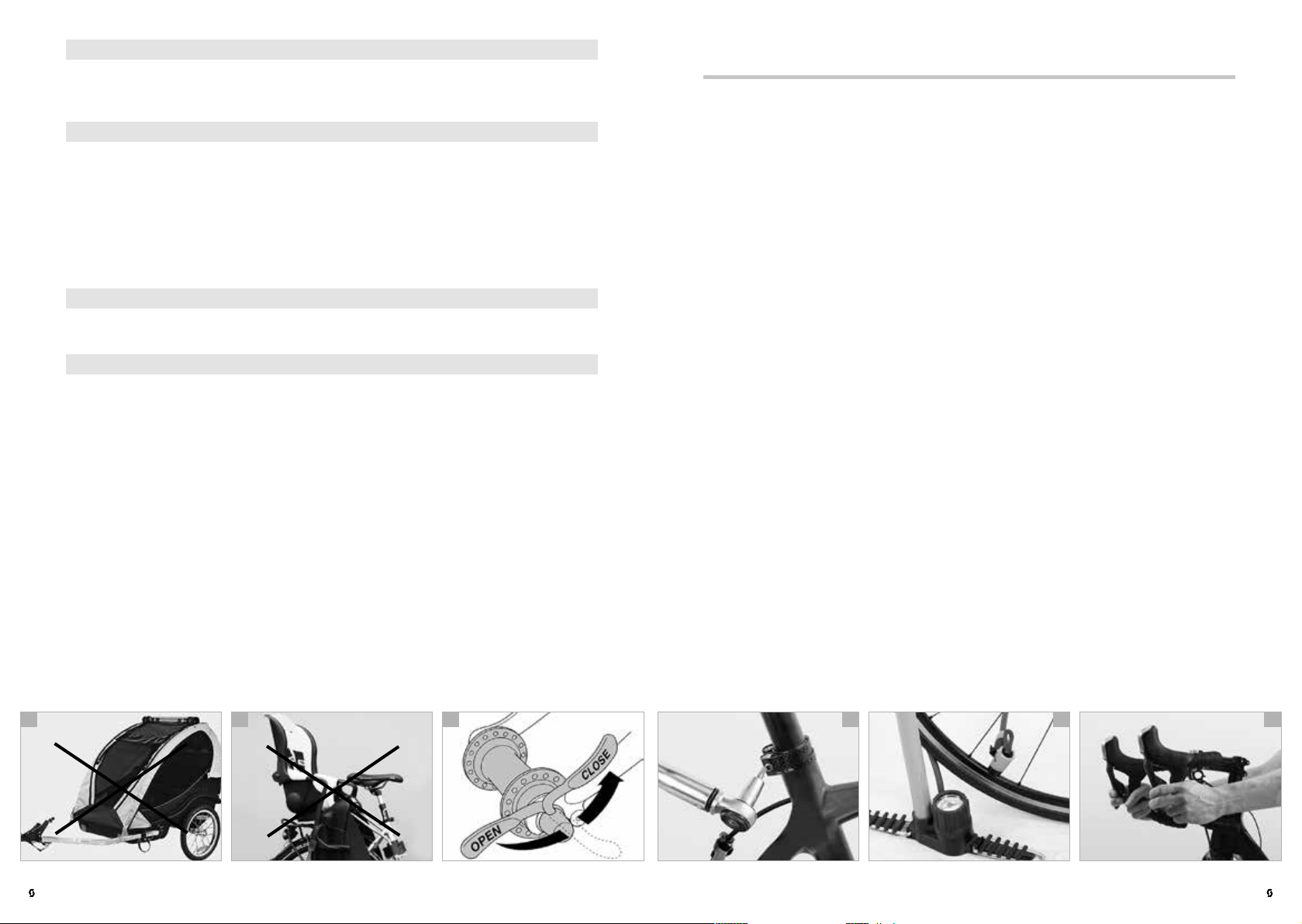
DANG ER!
For SCOTT road and triathlon bikes as well as time trial machines trailers
G
(a), child carriers (b) and pannier racks are not permitted.
NOTE!
We recommend that you take out private liability insurance. Make sure that
I
coverage for bicycle damage is provided by your insurance. Contact your
insurance company or agency.
b ca e fd
2. Are the tyres in good condition and do they have sufficient pressure (e)? The
minimum and maximum pressure (in bar or PSI) is indicated on the tyre side.
For more information see the chapter “Wheels and tyres” and the manuals of
the component manufacturers on this SCOTT info CD.
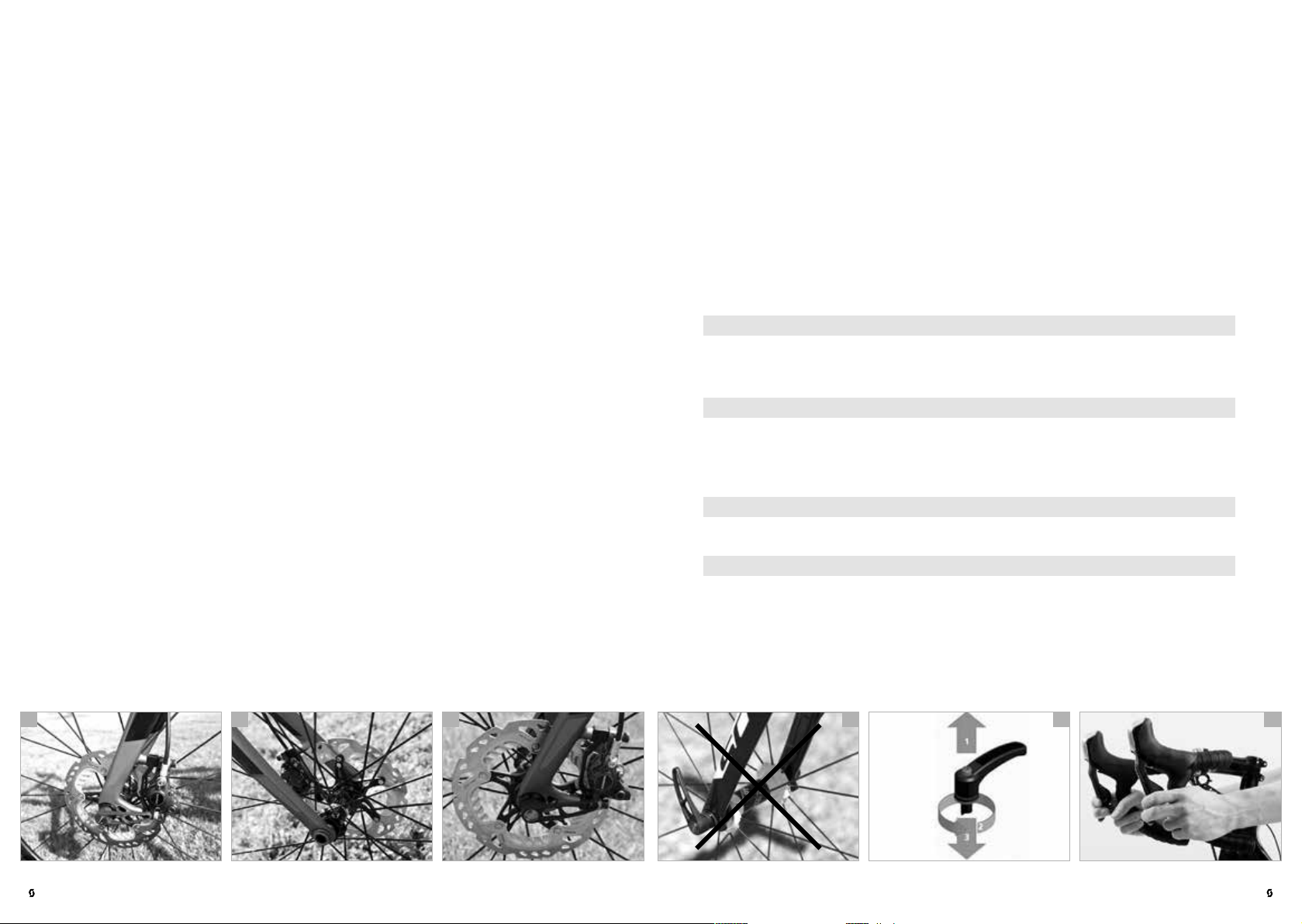
3. Spin the wheels to check whether the rims are true. If you have disc brakes,
watch the gap between frame and rim or tyre and, if you have rim brakes,
between brake pad and rim. Untrue rims can be an indication of tyres with
ruptured sides or broken spokes.
For more information see the chapter “Wheels and tyres” and the manuals of
the component manufacturers on this SCOTT info CD.
4. Test the brakes in stationary by firmly pulling the brake levers towards the
handlebars (f). The brake pads of rim brakes must hit the rim evenly with
their entire surface without touching the tyre during braking, in open condition or in between.
You should not be able to pull the lever all the way to the handlebars. If your
bike has hydraulic brakes, check the hydraulic brake cables for oil or brake
fluid leaks! Check the thickness of the brake pads, as well.
| 18
ROAD BI KE | OWNER’S MANUAL 2017OWNER’S MANUAL 2017 | ROAD BIKE
ENGLISHENGLISH
19 |
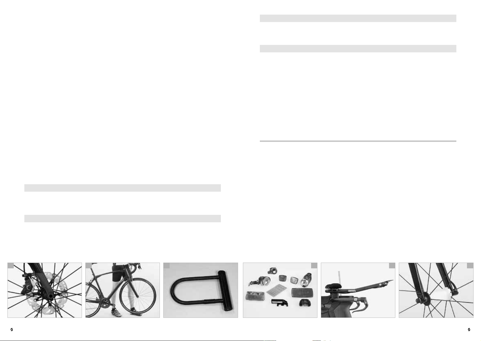
With disc brakes (a) you should have a stable pressure point at once. If you
have to actuate the brake lever more than once to get a positive braking
response, have the SCOTT bike checked by your SCOTT dealer immediately.
For more information see the chapter “Brakes” and the manuals of the component manufacturers on this SCOTT info CD.
5. Let your SCOTT bike bounce on the ground from a small height (b). If there
is any rattling, check where it comes from. Check the bearings and bolted
connections, if necessary. Tighten them slightly, if necessary.
6. If your bike has a kickstand, make sure it is fully raised before you set off. Risk
of falling!
7. Do not forget to take a high quality D- (c) or chain lock with you on your ride.
The only way to effectively protect your SCOTT bike against theft is to lock it
to an immovable object.
8. If you want to ride on public roads, make sure your SCOTT bike is equipped
according to the applicable regulations of your country (d). Riding without
lights and reflectors in dark or dim conditions is very dangerous because
you will be seen too late or not at all by other road users. A set of lights that
corresponds to the regulations is a must on public roads. Turn on the lights as
soon as dusk sets in.
For more information see the chapter “Legal requirements for riding on pub-
lic roads“.
DANG ER!
Do not use your SCOTT bike, if it fails at one of these points! A defective
G
SCOTT bike can lead to serious accidents! If you are in doubt or if you have
any questions, contact your SCOTT dealer.
DANG ER!
Improperly closed fastenings, e.g. quick-releases, can cause parts of your
G
SCOTT bike to come loose and result in serious accidents!
DANG ER!
Be aware that the distance you need to stop your bike increases, when you
G
are riding with your hands on aero bars or on triathlon bars (e). The brake
levers are not always within easy reach.
DANG ER!
During use your SCOTT bike is undergoing stress resulting from the surface
G
of the road and from the rider’s action. Due to these dynamic loads, the different parts of your bike react with wear and fatigue. Please check your SCOTT
bike regularly, i.e. according to the SCOTT service and maintenance schedule,
for wear marks, scratches, deformations, colour changes and any indication
of cracking. Components which have reached the end of their service life may
break without previous warning. Let your SCOTT dealer maintain and service
your SCOTT bike regularly, i.e. according to the SCOTT service and maintenance
schedule. In cases of doubt it is always best to replace components.
USING QUICK-RELEASES AND THRU AXLES
QUICK-RELEASES ON THE SCOTT BIKE
Most SCOTT bikes are fitted with quick-releases to ensure fast adjustments,
assembly and disassembly. Be sure to check whether all quick-releases are tight
before you set off on your SCOTT bike. Quick-releases should be handled with
greatest care, as they affect your safety directly.
Practise the proper use of quick-releases to avoid any accidents.
Quick-release retention mechanisms essentially consist of two operative elements (f):
1. The hand lever on one side of the hub which creates a clamping force via a
cam when you close it.
2. The tightening nut on the other side of the hub with which the preload on
the threaded rod (quick-release axle) is set.
| 20
b ca e fd
ROAD BI KE | OWNER’S MANUAL 2017OWNER’S MANUAL 2017 | ROAD BIKE
1
2
ENGLISHENGLISH
21 |
DANG ER!
Do not touch the brake disc directly after having stopped, e.g. after a long
G
down-hill ride, you may burn your fingers! Always let the brake disc cool
down before opening the quick-release.
Safe fastening of a component with a quick-release
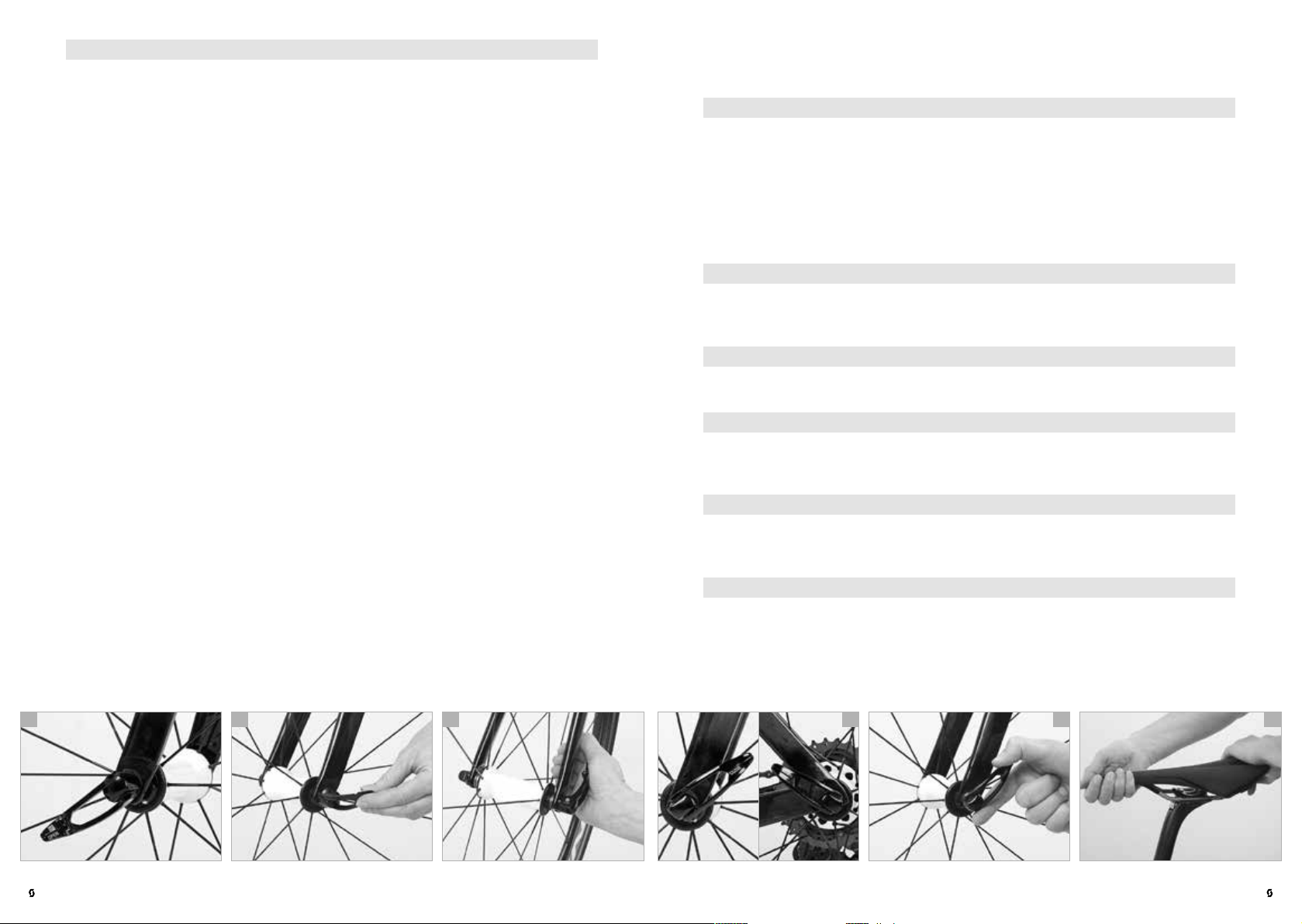
Open the quick-release. You should now be able to read “Open“ (a) on the lever.
Make sure the component to be fastened is in the accurate position.
For more information see the chapters “Adjusting the SCOTT bike to the rider”
and “Wheels and tyres” and the manuals of the component manufacturers on
this SCOTT info CD.
Move the lever back, as if to close it. Now you should be able to read ”Close“ on
the outside of the lever. When you start closing the lever you should feel virtually no resistance with your hand until the lever is at a right angle to the frame/
fork (b).
When continuing to close the lever the resistance you feel should increase significantly and towards the end even more strength is required to close the lever. Use
the ball of your thumb while your fingers pull on an immovable part, such as the
fork (c) or a rear stay, but not on a brake disc or spoke, to push it in all the way.
In its end position, the lever should be at a right angle to the quick-release axle
(d), i.e. it should not stand out. The lever should lie close to the frame or the fork
so that it cannot be opened accidentally. Make sure, however, that the lever is
easy to handle for actual quick use.
To check whether the lever is securely locked apply pressure to the end of
the hand lever and try to turn it while it is closed (e). If you can turn the lever
around, open it and increase the preload. Screw the tightening nut on the opposite side clockwise by half a turn. Close the quick-release lever and check it
again for tightness.
Finally lift the bike a few centimetres, so that the wheel no longer touches the
ground and hit the tyre from above. If it is properly fastened, the wheel will
remain firmly fixed in the drop-outs of the frame or fork without producing any
rattling.
If your seat post is equipped with a quick-release mechanism, check whether
the saddle is firmly fixed by trying to twist it relative to the frame (f).
DANG ER!
Make sure the levers of both wheel quick-releases are always on the side
G
opposite to the chain. This will help you to avoid mounting the front wheel
accidentally the wrong way round. In the case of SCOTT bikes with disc brakes
and quick-releases having a 5-mm-axle, it may be reasonable to mount both
quick-releases with the lever on the side of the chain drive. This helps you not
to come into contact with the hot brake disc and prevents you from having
your fingers burnt. If you are in doubt or if you have any questions, contact your
SCOTT dealer.
DANG ER!
Never ride your SCOTT bike without having checked first, whether the
G
wheels are securely fastened. With an insufficiently closed quick-release
the wheel can come loose, thus creating a serious risk of accident!
CAUTION!
If your SCOTT road bike has thru axles, read the manuals of the thru-axle
A
and wheel manufacturers on this SCOTT info CD.
CAUTION!
If your SCOTT bike is equipped with quick-releases, be sure to lock the
A
frame to an immovable object together with the wheels when you leave it
outside. Anti-theft protection!
NOTE!
To be on the safe side you can replace the quick-releases by special locks.
I
They can only be opened and closed with a special, coded key or an Allen
key. If you are in doubt or if you have any questions, contact your SCOTT dealer.
DANG ER!
After wheel mounting test the brakes in stationary. You should reach the
G
pressure point of the brake before the brake lever reaches the handlebars.
In the case of hydraulic brakes pump them, if necessary, until you reach a precise pressure point.
| 22
b ca e fd
ROAD BI KE | OWNER’S MANUAL 2017OWNER’S MANUAL 2017 | ROAD BIKE
ENGLISHENGLISH
23 |

DT Swiss RWS quick-release system
The RWS system from DT Swiss (a-c) for road racing and cyclo-cross racing
bikes is a special type of quick-release for front and rear wheels. The RWS system is compatible with all standard drop-outs.
Make sure during the assembly that the axles, the hubs, the drop-outs of the
fork and the rear frame are clean. Clean the components with an absorbent
cloth, if necessary, by using water and a little detergent.
In case you do not succeed in adjusting and fixing the wheel, as described, contact your SCOTT dealer.
Wheel mounting
Put the front wheel into the fork and mount the rotor simultaneously, if necessary, in the brake calliper. Make sure that in the area of the rear wheel the chain
runs over the sprockets and over both pulleys of the rear derailleur.
Bring the front or the rear wheel into the correct position between the dropouts and the fork or rear frame and slide the RWS quick-release axle from the
left side through the drop-outs and the hub. Mount the lock nut on the right
side.
Hold the lock nut on the right side of the hub tight. Turn the RWS quick-release
lever clockwise to pre-tighten the RWS system. Depending on the fork mounted
or the frame model, the number of turns you need varies. You need at least six,
in most cases however more turns. During the first turns you should be able to
turn the RWS quick-release lever nearly without resistance.
Turn the quick-release lever subsequently forcefully clockwise until the axle is
hand-tight.
Make sure the RWS quick-release lever does not stand out to the front (d). Open
the RWS quick-release lever a little (e, position 1) to bring it into a favourable
position. Turn the quick-release lever then into the desired position (e, position 2)
and re-close it towards the hub (e, position 3).
Close the release lever of the brake or hook in the cable. Actuate the brake lever
to make the brake work. The brake pads of rim brakes must hit the rim evenly
with their entire surface without touching the tyre during braking, in open condition or in between.
Lift the wheel and give it a strong tap from above. The wheel must be securely
fixed and must not rattle.
Wheel removal
To open the RWS system turn the quick-release lever anticlockwise (f) by holding the lock nut tight on the other side of the hub. Typically, you need not open
the RWS system completely. Open it only so far until the wheel slides off the
drop-outs. Open it fully only in exceptional cases and remove the axle completely from the hub.
DANG ER!
Improperly mounted wheels may throw you off your bike or result in
G
serious accidents! Therefore, if you have the slightest doubt, contact your
SCOTT dealer and ask him to explain the system of your SCOTT bike to you.
DANG ER!
After wheel mounting test the brakes in stationary. You should reach the
G
pressure point of the brake before the brake lever reaches the handlebars.
In the case of hydraulic brakes pump them, if necessary, until you reach a precise pressure point.
DANG ER!
Do not open the red screw to open or close the RWS system.
G
NOTE!
Before mounting or replacing a fork/wheel combination with thru-axle
system, be sure to read first the manuals of the respective fork or wheel
I
manufacturer on this SCOTT info CD. More information are provided at
www.dtswiss.com
| 24
b ca e fd
ROAD BI KE | OWNER’S MANUAL 2017OWNER’S MANUAL 2017 | ROAD BIKE
ENGLISHENGLISH
25 |
THRU AXLES ON THE SCOTT BIKE
The RWS system from DT Swiss (a-c) for road racing and cyclo-cross racing
bikes used by SCOTT are thru axles which provide the forks and the rear frames
with a higher stiffness. Whenever your SCOTT bike is exposed to high loads, it
remains directionally stable.
In the case of SCOTT road or cyclo-cross bikes with disc brakes the RWS
system is screwed on the right side. The system has a larger thread and can be
released with no more than two and a half turns. Make sure during the assembly
that the thru axles, the drop-outs of the fork and the hubs are clean. Clean the
components with an absorbent cloth, if necessary, by using water and a little
detergent.
In case you do not succeed in adjusting and fixing the wheel, as described, contact your SCOTT dealer.
You will feel an increasing resistance at the lever. Only turn the axle until it is
hand-tight.
Make sure the RWS quick-release lever does not stand out to the front (d).
Open the RWS quick-release lever a little (e, position 1) to bring it into a favourable position. Turn the RWS quick-release lever then into the desired position (e,
position 2) and re-close it towards the hub (e, position 3).
Actuate the brake lever to make the brake work. Lift the wheel and give it a
strong tap from above. The wheel must be securely fixed and must not rattle.
Wheel removal
Turn the quick-release lever anticlockwise to open the RWS system. Release the
thru axle completely by two and a half turns, hold the wheel in its position and
remove the axle from the hub.
Safe fastening of components with a quick-release
Wheel mounting
Put the wheel into the fork or the rear frame and mount the rotor simultaneously, if necessary, in the brake calliper. Make sure that in the area of the rear wheel
the chain runs over the sprockets and over both pulleys of the rear derailleur.
Bring the front wheel into the right position between the drop-outs and slide
the thru axle with open quick-release lever from the left side through the dropout and the hub.
As soon as you have reached the opposite side, turn the thru axle clockwise
into the nut on the right side. Do not apply force, but make sure the axle thread
engages properly with the nut on the other side.
During the first turn you should be able to turn the RWS quick-release lever of
the thru axle nearly without resistance. If everything fits, turn the RWS quick-release lever all in all two and a half turns clockwise to pre-tighten the RWS
system.
b ca e fd
DANG ER!
Improperly mounted wheels may throw you off your bike or result in
G
serious accidents! Therefore, if you have the slightest doubt, contact your
SCOTT dealer and ask him to explain the system of your SCOTT bike to you.
DANG ER!
After wheel mounting test the brakes in stationary. You should reach the
G
pressure point of the brake before the brake lever reaches the handlebars.
In the case of hydraulic brakes pump them, if necessary, until you reach a precise pressure point (f).
DANG ER!
Do not open the red screw to open or close the RWS system.
G
NOTE!
Before mounting or replacing a fork/wheel combination with thru-axle
I
system, be sure to read first the manuals of the respective fork or wheel
manufacturer on this SCOTT info CD. More information are also provided at
www.dtswiss.com
| 26
ROAD BI KE | OWNER’S MANUAL 2017OWNER’S MANUAL 2017 | ROAD BIKE
ENGLISHENGLISH
27 |
ADJUSTING THE SCOTT BIKE TO THE RIDER
Your body height and proportions are decisive for the frame size of your SCOTT
bike. Make particularly sure there is enough space between your crotch and the top
tube so that you do not hurt yourself, if you have to get off your bike quickly (a).
By choosing a specific type of bicycle you roughly determine the posture you
will be riding in (b+c). However, some components of your SCOTT bike are especially designed so that you can adjust them to your body proportions up to a
certain degree. This includes the seat post, the handlebars and the stem as well
as the brake levers/shifters.
As all works require know-how, experience, suitable tools and skills, you should
restrict yourself to adjusting your seating position. Contact your SCOTT dealer, if you are not happy with your seating position or if you want something
changed. They will see to your wishes the next time you leave your SCOTT bike
at the workshop, e.g. for the first inspection.
NOTE!
The seating position depends highly on how you want to use the SCOTT
I
bike. Ask your SCOTT dealer or your trainer for help. The advice given be-
low is suitable for typical SCOTT road bikes.
NOTE!
If sitting on the saddle causes you trouble, e.g. because it numbs your
I
crotch, this may be due to the saddle. Your SCOTT dealer has a very wide
range of saddles available and will be pleased to advise you.
ADJUSTMENT OF THE SADDLE TO THE CORRECT HEIGHT
The correct saddle height depends on the length of your legs. When pedalling, the ball of your foot should be positioned above the centre of the pedal
axle. With your feet in this position you should not be able to stretch your legs
completely straight at the lowest point, otherwise your pedalling will become
awkward (d).
After any adjustment/assembly work, be sure to make a short functional check
as described in the chapter “Tests before every ride” and do a test ride on your
SCOTT bike in an area free of traffic.
DANG ER!
If you have a very small frame, there may be the danger of your foot col-
G
liding with the front wheel. Therefore, make sure your cleats are properly
adjusted.
DANG ER!
All tasks described in the following require the know-how of a mechanic
G
and appropriate tools. Make it a rule to tighten the bolted connections
always with greatest attention. Increase the torque values bit by bit and check
the fit of the component in between. Use a torque wrench and never exceed the
maximum torque values! You will find the prescribed values in the chapter “Recommended torque settings for your SCOTT bike”, directly on the components
and/or in the manuals of the component manufacturers on this SCOTT info CD.
b ca e fd
Check the height of your saddle with flat-soled shoes. This is best done with
suitable cycling shoes.
Sit on the saddle and put your heel on the pedal at its lowest point. Your leg
should be fully stretched and your hips should remain horizontal (e).
To adjust the saddle height loosen the quick-release lever (see the chapter “Using quick-releases and thru axles“) or the binder bolt of the seat post clamp at
the top of the seat tube. The latter requires suitable tools, e.g. an Allen key, with
which you turn the bolt two to three turns anticlockwise. Now you can perform
the vertical adjustment of the seat post.
Be sure not to pull out the seat post too far – the mark on the seat post (f) (end ,
max., min., stop or the like) should always remain within the seat tube – and always grease the part of an aluminium or titanium seat post that is inserted into a
seat tube made of aluminium, titanium or steel. Do not grease carbon seat posts
and/or carbon seat tubes in the clamping area! Use special carbon assembly
paste instead.
| 28
ROAD BI KE | OWNER’S MANUAL 2017OWNER’S MANUAL 2017 | ROAD BIKE
ENGLISHENGLISH
29 |
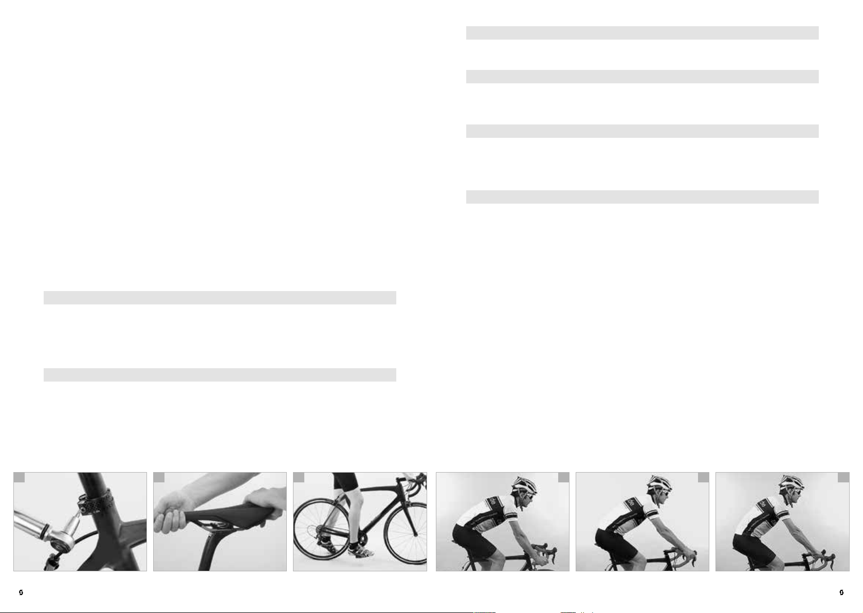
Align the saddle with the frame by using the saddle nose and the bottom bracket or top tube as a reference point. Clamp the seat post tight again by closing
the quick-release, as described in the chapter “Using quick-releases and thru
axles” or by turning the seat post binder bolts clockwise in half turns or better
in steps of 0.5 Nm increments starting at 3 Nm (a). You should not need much
strength in your hands to clamp the seat post sufficiently tight. Otherwise the
seat post does not match the frame.
Verify in between that the seat post is sufficiently tight by taking hold of the
saddle at both ends and then trying to rotate the seat post inside the seat tube
(b). If it does rotate, gently retighten the binder bolt of the seat post clamp by
half a turn or better by a quarter turn or in steps of 0.5 Nm increments and do
the check again.
Does the leg stretch test now produce the correct result? Check by moving your
foot and pedal to the lowest point. When the ball of your foot is exactly above
the pedal centre in the ideal pedalling position, your knee should be slightly
bent. If this is the case, the saddle height is adjusted to the correct height.
Check whether you can touch the ground safely while sitting on the saddle by
stretching your feet to the floor (c). If not, you should lower the saddle until you
can, at least to begin with.
DANG ER!
Never apply grease or oil into a seat tube of a frame made of carbon unless
G
an alloy sleeve is inside the frame. If you mount a carbon seat post, do not
put any grease on it, even if the frame is made of metal. Once greased, carbon
components may never again ensure reliable clamping! Use special carbon
assembly paste instead.
DANG ER!
Never ride your bike with the seat post drawn out beyond the limit, maxi-
G
mum, or stop mark! The seat post might break or cause severe damage to
the frame. In the case of frames with seat tubes that extend beyond the top of
the frame’s top tube the seat post should be inserted into the seat tube at least
below the bottom of the top tube and below the top of the rear stays! If seat
post and frame require different minimum insertion depths, you should opt for
the deeper insertion depth.
DANG ER!
Make sure not to overtighten the binder bolt of the seat post clamp. Other-
G
wise you may damage the seat post or the frame. Risk of accident!
CAUTION!
If the seat post does not move easily inside the seat tube or if it cannot be
A
tightened sufficiently, ask your SCOTT dealer for advice. Do not use brute
force!
CAUTION!
Tighten carefully by approaching the prescribed maximum torque value in
A
small steps (0.5 Nm increments) and check in between the proper fit of the
component. Never exceed the maximum torque value indicated by the manufacturer!
NOTE!
Children and adolescents need to have the saddle height and the position
I
of saddle and handlebars checked at least every 3 months!
ADJUSTMENT OF THE HEIGHT OF THE HANDLEBARS
In principle, SCOTT road bikes are sports bikes designed for speed. For this reason alone a SCOTT road bike sets certain basic requirements to the body, the
shoulder and the neck muscles. The height of the handlebars compared to the
saddle and the distance between saddle and handlebars determine how much
your upper body will be inclined forward. Lowering the handlebars gives you a
streamlined position and brings more weight to bear on the front wheel. However, it also entails an extremely forward leaning posture which is tiring and less
comfortable, because it increases the strain on your wrists, arms, back, upper
body and neck. As a general rule you should be able to adopt the three basic
positions (d-f ) on a SCOTT road bike without any problems with your hands
around the respective area on the handlebars.
In the case of SCOTT road bikes an Aheadset®-stem allows the vertical adjustment of the handlebars. This requires special knowledge. In this regard, the
descriptions hereafter may be incomplete. If you are in doubt or if you have any
questions, contact your SCOTT dealer.
| 30
b ca e fd
ROAD BI KE | OWNER’S MANUAL 2017OWNER’S MANUAL 2017 | ROAD BIKE
ENGLISHENGLISH
31 |
DANG ER!
The stem is one of the load-bearing parts of your SCOTT bike. Changes to
G
it can impair your safety. If you are in doubt or if you have any questions,
contact your SCOTT dealer!
DANG ER!
These routines require a certain amount of manual skill and (special) tools.
G
Ask your SCOTT dealer to explain you both function and adjustment of your
stem or let him do that work.
DANG ER!
The bolted connections of stem and handlebars have to be tightened to
G
the prescribed torque values. If you disregard the prescribed values, the
handlebars or stem may come loose or break. Use a torque wrench and never
exceed the maximum torque values! You will find the prescribed values in the
chapter “Recommended torque settings for your SCOTT bike”, directly on the
components and/or in the manuals of the component manufacturers on this
SCOTT info CD.
DANG ER!
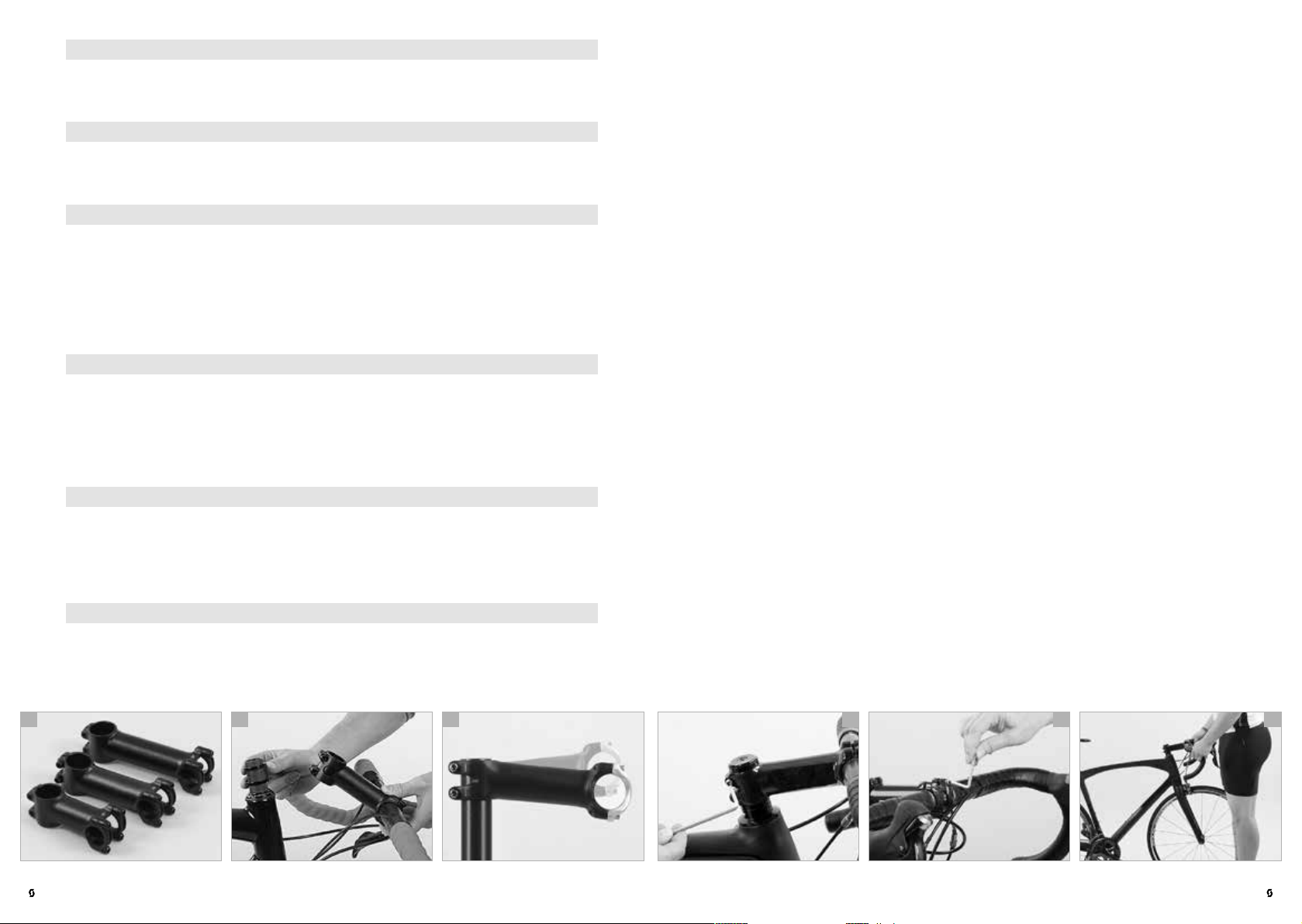
Stems come in varying lengths (a) as well as shaft and binder tube diam-
G
eters. A stem of inappropriate dimension can become a source of danger:
Handlebars, stems or forks can break, resulting in an accident. When replacing
any parts be sure to only use parts that bear the appropriate mark and, to be on
the safe side, original spare parts from SCOTT or SYNCROS. Your SCOTT dealer
will be pleased to help you.
CAUTION!
If you choose to use the product of another manufacturer, make sure it is
A
compatible with the S COTT/SYNCROS components. SCOTT assumes no
responsibility for problems resulting from the use of non-S COTT/SYNCROS
products. Make sure the handlebar/stem-combination is approved by the handlebar and/or stem manufacturer.
CAUTION!
Make sure the handlebar clamping area is free of sharp edges.
A
Stems for threadless systems – Aheadset®
In the case of SCOTT bikes with Aheadset® headsets the stem also serves to
adjust the bearing preload. If you change the position of the stem, you have to
readjust the bearing play (see the chapter “The headset on the SCOTT bike” and
the manuals of the component manufacturers on this SCOTT info CD).
The vertical setting range is determined by the intermediate rings, also referred
to as spacers (b). In the case of flip-flop stem models the stem can be mounted
the other way round (c) to achieve a different handlebar height.
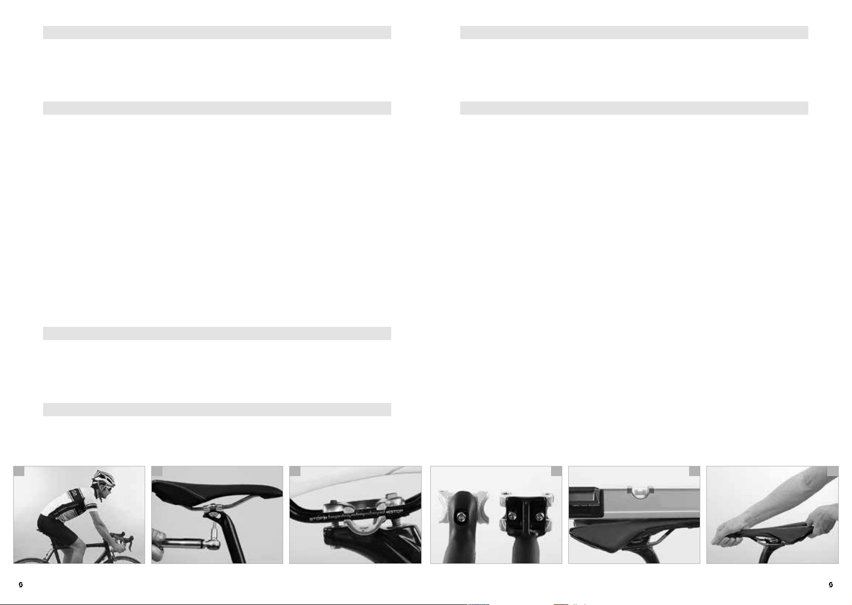
For modifications unscrew the bolt at the top of the fork steerer tube which
serves to adjust the initial bearing pressure, remove the Ahead cap and release
the bolts on either side of the stem by up to three turns (d). Remove stem and
spacers from the fork steerer tube. In doing so keep hold of both frame and
fork to prevent the fork from slipping off the head tube. You can determine the
handlebar height by the arrangement of stem and spacers. Slip the remaining
spacers onto the fork steerer tube above the stem. Adjust the headset, as described in the chapter “The headset on the SCOTT bike“.
If you want to turn the stem around, you have to also release the bolts of the
faceplate securing the handlebars (e). If the stem is fitted with a cap, you can
simply take out the handlebars at this point. If it is not fitted with a cap, you have
to remove the handlebar fittings.
Mount the handlebars and, if necessary, the handlebar fittings, as described in
the chapter “Adjustment of handlebar tilt and brake lever/shifter units on SCOTT
road bikes and SCOTT cyclo-cross bikes” and/or in the manuals of the component manufacturers on this SCOTT info CD.
Check after the adjustment or assembly, whether the handlebars are firmly seated in the stem by trying to rotate the handlebars downwards (f). Verify whether
the handlebar/stem-combination can be turned relative to the fork. Do this by
taking the front wheel between your knees and trying to twist the handlebars.
If there is movement, carefully tighten the bolts a little more by using the torque
wrench, observe the maximum torque value and check again the proper fit.
Tighten carefully by approaching the prescribed maximum torque value in small
steps (0.5 Nm increments) and check in between the proper fit of the component.
| 32
b ca e fd
ROAD BI KE | OWNER’S MANUAL 2017OWNER’S MANUAL 2017 | ROAD BIKE
ENGLISHENGLISH
33 |
Never exceed the maximum torque value indicated by SCOTT! Ask your SCOT T
dealer to explain you both function and adjustment of your stem or, still better,
let him do that work.
DANG ER!
In the case of turned stems, it is possible that the cables are too short. In
G
this case riding can be unsafe. If in doubt, ask your SCOTT dealer.
DANG ER!
When removing spacers (a) the fork steerer tube must be shortened. This
G
change is irreversible. The shortening should be carried out by your SCOTT
dealer, but only after you have found your preferred position.
4. Apply a thin and even layer of grease on the bearings before mounting the
fork in the frame. Make sure the clamping surfaces of the stem remain clear
of grease. Otherwise there is the risk that a secure clamping of the stem is
no longer possible. Apply special carbon assembly paste on the inside of
the stem as well as on the fork steerer inside and outside in the area of the
clamping. This increases the friction and ensures a secure fit.
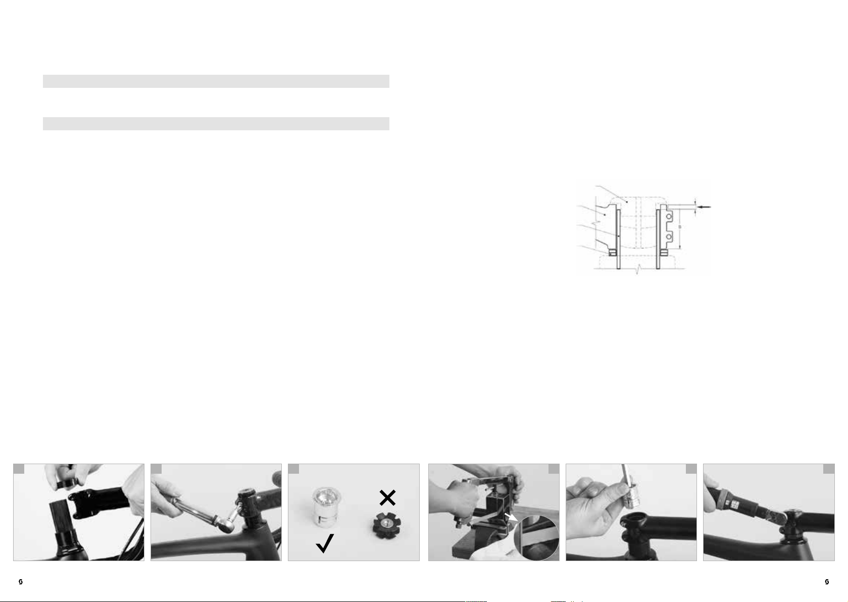
5. Slide the expander into the carbon steerer until it is flush with the top of the
steerer.
6. Tighten the expander by using an 8-mm Allen key to a maximum torque
value of 4-5 Nm making sure that the expander stays flush with the top of the
steerer (e). Make sure there is no more than 2.5 mm between the top of the
stem clamp and the top of the steerer as shown on the illustration.
What to bear in mind with SCOTT bikes with carbon steerer
Always make sure before assembly to use a headset compatible with the stem.
We recommend the use of a SYNCROS stem and headset when mounting a
SCOT T/SYNCROS carbon fork, as they are designed to work together. If you
choose to use the product of another manufacturer, make sure it is compatible
with the SCOT T/ SYNCROS fork. SCOTT assumes no responsibility for problems
resulting from the use of non-S COTT/SYNCROS products.
Never use more than 40 mm stack height of spacers between headset and stem
(b). Never use more than 5 mm stack height of spacers above the stem between
the stem and the top cap of the headset (b). Do use a minimum of 5 mm stack
height of spacers below the stem between the cap of the headset and the stem.
1. The fork steerer, especially in case of a carbon steerer, must be assembled
with the originally supplied internal expander wedge. Never use a standard
star flanged nut on carbon fork steerers (c).
2. When cutting the steerer tube use handtools only. Do not use a power saw or
a speed cutter, but use a hand saw with a fine blade for metal cutting (d) and
a saw guide.
3. Once the steerer tube is cut to the desired length, be sure to remove all burrs
at the top of the steerer tube. Make sure to wear appropriate safety protection, safety goggles, gloves and breathing mask. Avoid inhaling the carbon
dust. Do not blow or sweep the dust off, but remove it with a moist rag. Dispose of it immediately.
b ca e fd
Top c a p
Stem
Steerer tube
Spacers
7. Clamp the stem onto the steerer tube with a maximum of 6 Nm (f) and
respect also the maximum torque value of the stem manufacturer. The lower
value indicated on these components has to be accepted as a maximum
torque value. Do not overtighten!
8. Make sure the stem has no sharp edges on the contact area for the steerer or
the handlebar. This could result in serious accidents. In case you change your
stem to another model or brand, please contact your authorized SCOT T/
SYNCROS dealer. SCOTT will not be liable in case a not originally provided
SCOTT or SYNCROS stem is used on the bike assembly. In case of further
questions, please contact your authorized SCOT T/SYNCROS dealer or the
national distributor of SCOT T/SYNCROS.
max.
2.5mm
| 34
ROAD BI KE | OWNER’S MANUAL 2017OWNER’S MANUAL 2017 | ROAD BIKE
ENGLISHENGLISH
35 |
DANG ER!
Modifications in the area of the carbon forks are jobs which should be left
G
to a skilled two-wheel/bicycle mechanic. SCOTT therefore recommends
that you ask your SCOTT dealer to do any work on the carbon fork, whenever
necessary. Wrong processing and unfavourable stems may lead to breakage.
Risk of accident!
DANG ER!
The setting range of the saddle is very small. Replacing the stem allows you
G
to make far bigger adjustments to the rider’s fore-to-aft position, as stems
come in different lengths. In doing so you may achieve differences of more than
ten centimetres. In this case you usually would have to adjust the length of the
cables – a job best left to your SCOTT dealer!
DANG ER!
Sawdust from cutting carbon components has a reputation of causing can-
G
cer. Therefore, do not blow or sweep the dust off, but remove it with a moist
rag. Dispose of it immediately.
SADDLE ADJUSTMENT – FORE-TO-AFT POSITION AND HORIZONTAL
TILT
The inclination of your upper body (a), and hence your riding comfort and
pedalling power, are also influenced by the distance between the grips of the
handlebars and the saddle. This distance can be altered slightly by changing the
position of the saddle rails in the seat post clamp. However, this also influences
your pedalling. Whether the saddle is positioned more to the front or to the
back of the bike will alter how rearward the pedalling position of your legs is.
Make sure the saddle is clamped within the range of the marking on the saddle
rail, i.e. on the straight part of the rail, never in the curved sections.
You need to have the saddle horizontal in order to pedal in a relaxed manner.
If it is tilted, you will constantly have to lean against the handlebars to prevent
yourself from slipping off the saddle.
DANG ER!
The bolted connections of the seat post have to be tightened to the pre-
G
scribed torque values (b). Use a torque wrench and never exceed the maximum torque values! You will find the prescribed values in the chapter “Recommended torque settings for your SCOTT bike”, directly on the components and/
or in the manuals of the component manufacturers on this SCOTT info CD.
DANG ER!
Make sure the saddle is clamped within the range of the marking on the
G
saddle rail and not in the curved section of the saddle rails (c). Otherwise
the saddle rail can fail! Check the bolts by using a torque wrench once a month
according to the prescribed values.
b ca e fd
NOTE!
The manufacturers of saddles deliver their products with detailed manuals.
I
You find these manuals on this SCOTT info CD. Read them carefully before
adjusting the position of your saddle. If you are in doubt or if you have any questions, contact your SCOTT dealer.
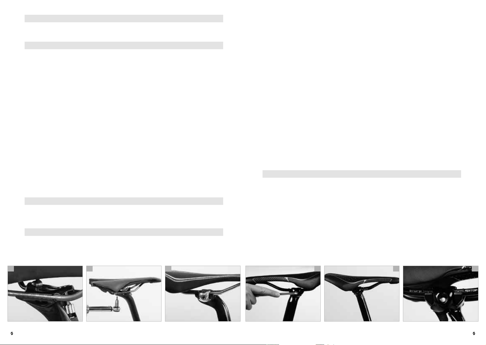
Adjustment of saddle position and tilt
With patent seat posts (d) one or two bolts fix the clamping mechanism, which
controls the tilt and the horizontal position of the saddle. Some seat posts have
two bolts side-by-side.
Release the bolt(s) at the top of the seat post. Release the bolt(s) two to three
turns anticlockwise at the most, otherwise the whole assembly can come apart.
Move the saddle forth or back, as desired. You may have to give the saddle a
light blow to make it move.
Please observe the markings on the saddle rail. Make sure the seat of the saddle
remains horizontal (e) as you retighten the bolt(s). Your SCOTT bike should
stand on level ground while you adjust the saddle.
Having found your preferred position, make sure both clamp halves fit snugly
around the saddle rails before tightening the bolt(s) to the correct torque value
as prescribed by the seat post manufacturer.
Retighten the bolt(s) with a torque wrench according to the manuals of the
manufacturer. After fastening the saddle, check whether it resists tilting by
bringing your weight to bear on it once with your hands at either end of the
saddle (f).
| 36
ROAD BI KE | OWNER’S MANUAL 2017OWNER’S MANUAL 2017 | ROAD BIKE
ENGLISHENGLISH
37 |
DANG ER!
Poorly tightened or loosening bolts can fail. Risk of accident!
G
DANG ER!
Check the bolts by using a torque wrench once a month according to the
G
values indicated directly on the components and/or in the manuals of the
component manufacturers on this SCOTT info CD.
Clamping with two bolts in line (a): Release both bolts two to three turns
anticlockwise, otherwise the whole assembly can come apart. Move the saddle
forward or backward as desired to adjust the horizontal position. You may have
to give the saddle a light blow to make it move. Please observe the markings on
the saddle rail.
Having found your preferred position, make sure both clamp halves fit snugly
around the saddle rails before tightening the bolt(s) to the correct torque value
as prescribed by the seat post manufacturer.
Tighten both bolts evenly (b) so the saddle remains at the same angle. If you
wish to lower the nose of the saddle a little, tighten the front bolt clockwise. You
might have to loosen the rear bolt a little as well. To lower the rear part of the
saddle, the rear bolt has to be tightened clockwise and the front bolt has to be
released, if necessary.
After fastening the saddle, check whether it resists tilting by bringing your
weight to bear on it once with your hands at either end of the saddle.
If you have a single bolt system (c), the seat post for most of the sports saddles
is designed for a saddle rail diameter of 7 mm.
Replacement outer clamps for ovalized saddle rails of 8 mm x 8.5 mm (W x H)
as well as for carbon saddle rails bigger than 8 x 8.5 mm are also available. If
you are not sure which saddle rail type you have or if you need further information, contact your SCOTT dealer.
To mount the saddle unscrew the transversal fixing bolt (d) as far as possible
without loosening the lock nut on the outer side of the clamping device. In general, it is not necessary to take the mechanism completely apart, if it is already
equipped with the correct outer clamps for your saddle.
If you do find it necessary to unscrew the single fixing bolt completely, remove
it from the clamping device. This releases the outer clamping parts. The inner
clamping parts are typically held in position with a rubber retention plate.
Mount the saddle rails into the inner clamping parts, add the outer parts and
re-insert the fixing bolt. If the width of the saddle rails does not fit exactly into
the clamp grooves, do not try to force them in. The clamping mechanism or the
saddle rails could break and result in an accident and/or injuries to the rider.
Use a different saddle model (e) or contact your SCOTT dealer.
DANG ER!
When choosing another saddle, observe that there are round and ovalized
G
rails. Replace the fitting pieces of the clamp accordingly.
| 38
DANG ER!
Check the bolts by using a torque wrench once a month according to the
G
values indicated directly on the components and/or in the manuals of the
component manufacturers on this SCOTT info CD.
DANG ER!
Poorly tightened or loosening bolts can fail. Risk of accident!
G
b ca e fd
If the saddle rails fit into the clamp grooves, slide the saddle on the seat post
and ensure that the clamp is positioned midway along the total length of the
rails (f).
ROAD BI KE | OWNER’S MANUAL 2017OWNER’S MANUAL 2017 | ROAD BIKE
ENGLISHENGLISH
39 |
 Loading...