

Scott AIR-PAK 75i 2.2,AIR-PAK 75i 4.5 Operating & Maintenance Instructions
OPERATING & MAINTENANCE INSTRUCTIONS
SCOTT AIR-PAK 75i
Industrial Pressure-Demand
Self Contained Breathing Apparatus (SCBA)
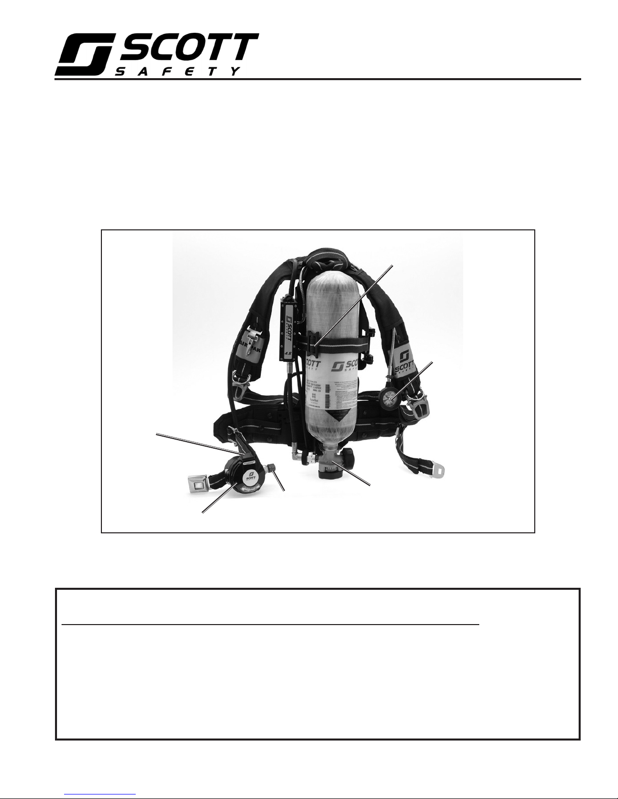
AIR SAVER
SWITCH
BREATHING
REGULATOR
Models
PURGE
VALV E
2.2 / 4.5
CYLINDER
VALV E
TRI-SLIDE
BUCKLE
REMOTE
PRESSURE
GAUGE
Typical configuration of SCOTT AIR-PAK 75i SCBA's shown.
Appearance of respirators may vary depending on optional and accessory equipment.
IMPROPER USE OF THIS RESPIRATOR MAY RESULT IN PERSONAL INJURY OR DEATH. IMPROPER USE INCLUDES, BUT IS NOT LIMITED TO, USE WITHOUT ADEQUATE TRAINING, DISREGARD OF THE WARNINGS AND
INSTRUCTIONS CONTAINED HEREIN, AND FAILURE TO INSPECT AND MAINTAIN THIS RESPIRATOR. READ AND
UNDERSTAND ALL INSTRUCTIONS BEFORE ATTEMPTING TO OPERATE OR SERVICE THIS EQUIPMENT.
THIS RESPIRATOR IS INTENDED TO BE USED ONLY IN CONJUNCTION WITH AN ORGANIZED RESPIRATORY
PROTECTION PROGRAM WHICH COMPLIES WITH THE REQUIREMENTS OF "PRACTICES FOR RESPIRATORY
PROTECTION," Z88.2 AVAILABLE FROM AMERICAN NATIONAL STANDARDS INSTITUTE INC., 1430 BROADWAY, NEW YORK, N.Y., 10018, OR THE REQUIREMENTS OF OSHA SAFETY AND HEALTH STANDARD 29 CFR
1910 PARAGRAPH 134 AVAILABLE FROM THE U. S. DEPARTMENT OF LABOR, OCCUPATIONAL SAFETY
AND HEALTH ADMINISTRATION, OR OTHER PERTINENT NATIONALLY RECOGNIZED STANDARDS, SUCH
AS THOSE PROMULGATED BY THE U. S. COAST GUARD OR THE DEPARTMENT OF DEFENSE.
© 2011 Scott Safety. SCOTT, the SCOTT SAFETY Logo, Scott Health and Safety, AIR-PAK, PAK-ALERT, VIBRALERT, AV-2000, AV3000, and SURESEAL are registered and/or unregistered marks of Scott Technologies, Inc. or its affiliates.
TYPICAL AIR-PAK 75i SCBA
WARNING
Page 1 of 44
P/N 595236-01 Rev. B 10/11

SCOTT AIR-PAK 75i
Industrial Pressure-Demand
Self Contained Breathing Apparatus (SCBA)
Models
2.2 / 4.5
DESCRIPTION
The SCOTT AIR-PAK 75i self contained breathing apparatus (SCBA)
is intended to provide respiratory protection to an individual when
entering into, working in, and exiting from an objectionable, oxygen
deficient, and/or unbreathable (toxic) atmosphere.
TRAINING IS REQUIRED BEFORE USE. The SCOTT AIR-PAK 75i
SCBA respirator is to be used only by persons trained in the use of
the respirator and only in conjunction with an organized respiratory
protection program. The SCBA must be used and maintained properly.
This respirator is not to be used under water, for interior structural fire
fighting or for any other purpose not authorized by the organized respiratory protection program that applies specifically to the user.
At a minimum, the SCOTT AIR-PAK 75i SCBA consists of the
following:
– a cylinder and valve assembly to store a supply of breathing air
under pressure,
– a backframe and harness assembly to support the cylinder and valve
assembly and pressure reducer on the body,
– a backframe mounted pressure reducer with a remote pressure
gauge,
– a facepiece mounted pressure demand breathing regulator with an
air saver switch,
– a SCOTT full facepiece and a head harness to secure the facepiece
to the face.
All SCOTT AIR-PAK 75i SCBA’s described in this instruction are
equipped with one end of service time indicator, a remote pressure
gauge mounted on the shoulder strap, and an air saver switch located
on the breathing regulator. All model respirators described by these
instructions are equipped with shoulder straps, waist straps and head
harnesses are made of Kevlar1.
The full facepiece is available in a variety of models and sizes and
must be properly fitted to the user before use. The facepiece design
incorporates a nose cup, two inhalation valves and dual voicemitter
assemblies. The facepiece detaches from the breathing regulator to
allow for use of the best fitting and most comfortable size facepiece
for each user. Fit testing per OSHA Standard 29 CFR Part 1910 or
ANSI Standard Z88.2 requires testing in the negative pressure mode
using equipment such as a Portacount Plus2 Respirator Fit Tester.
For this, SCOTT facepieces require use of SCOTT Fit Test Adapter
P/N 804057-01 or equivalent and appropriate negative pressure testing equipment. Mask Seal Kit P/N 805655-01 may also be required to
attain a proper fit.
1
Kevlar is a registered trademark of E.I. du Pont de Nemours, Inc.
2
Portacount Plus is a registered trademark of TSI Incorporated
DO NOT OPERATE THIS EQUIPMENT WHILE
WARNING
UNDER THE INFLUENCE OF DRUGS, ALCOHOL, OR ANY MEDICATIONS OR SUBSTANCES
WHICH MAY AFFECT VISION, DEXTERITY, OR
JUDGMENT. USERS OF THIS EQUIPMENT
MUST BE IN GOOD PHYSICAL AND MENTAL
HEALTH IN ORDER TO OPERATE SAFELY.
DO NOT USE THIS EQUIPMENT WHEN FATIGUE PREVENTS SAFE OPERATION. STAY
ALERT WHEN OPERATING THIS EQUIPMENT.
INATTENTION OR CARELESSNESS WHILE
OPERATING THIS EQUIPMENT MAY RESULT
IN SERIOUS INJURY OR DEATH.
WARNING
THIS RESPIRATOR, IS INTENDED TO PROTECT THE USER ONLY FROM THE EFFECTS
OF AN OXYGEN DEFICIENT ATMOSPHERE
AND/OR ATMOSPHERES CONTAINING TOXIC
OR HAZARDOUS SUBSTANCES BY PROVIDING A SUPPLY OF RESPIRABLE BREATHING
AIR TO A FACEPIECE SEALED TO THE USER'S FACE.
WHEN PROPERLY USED, THIS RESPIRATOR
PROVIDES PROTECTION FROM AIRBORNE
TOXIC OR HAZARDOUS SUBSTANCES ONLY
TO THE EYES AND RESPIRATORY SYSTEM.
IMPROPER USE OF THIS RESPIRATOR MAY
RESULT IN SERIOUS INJURY OR DEATH.
WARNING
RESPIRATORS SHALL NOT BE WORN
WHEN CONDITIONS PREVENT A GOOD
FACE TO FACEPIECE SEAL OR A GOOD
SEAL AROUND THE NOSE CUP. SUCH
CONDITIONS MAY INCLUDE, BUT ARE NOT
LIMITED TO, GROWTH OF BEARDS, SIDEBURNS, A SKULL CAP THAT PROJECTS UNDER THE FACEPIECE, OR TEMPLE PIECES
ON GLASSES. ALSO, THE ABSENCE OF ONE
OR BOTH DENTURES CAN SERIOUSLY EFFECT THE FIT OF THE FACEPIECE. USE
OF THE RESPIRATOR WITHOUT A GOOD
FACE TO FACEPIECE SEAL OR A GOOD
SEAL AROUND THE NOSE CUP SEAL MAY
REDUCE THE DURATION OF USE AND/OR
EXPOSE THE USER TO THE ATMOSPHERE
THE RESPIRATOR IS INTENDED TO PROTECT AGAINST RESULTING IN SERIOUS
INJURY OR DEATH.
P/N 595236-01 Rev. B 10/11
Page 2 of 44

The removable pressure-demand breathing regulator mounts directly to
the facepiece. The air saver/donning switch on the breathing regulator
prevents the rapid loss of the air supply if the cylinder valve is open
and if the facepiece is removed from the face or the regulator is removed
from the facepiece. The red purge knob on the regulator allows air to
flow into the facepiece in an emergency as well as to release residual
air from the respirator after the cylinder valve is turned off.
All models of the AIR-PAK 75i SCBA respirator are equipped with the
VIBRALERT alarm in the facepiece mounted regulator. The VIBRALERT
alarm serves two functions: as an end of service time indicator, and
to alert the user of a malfunction in the dual path pressure reducer. In
normal operation, the VIBRALERT alarm vibrates the breathing regulator
and facepiece to warn the user by both sound and feel that approximately
25% of full cylinder pressure remains. In addition, the VIBRALERT alarm
will be activated to warn the user if there is a malfunction in the primary
path of the dual path pressure reducer. Air is normally supplied through
the primary air path of the pressure reducer. If the primary air path of
the pressure reducer becomes blocked or should fail closed, the secondary air path will automatically begin supplying air to the breathing
regulator and the VIBRALERT alarm will be actuated to warn the user
of the malfunction.
An optional independent end of service time indicator alarm is the
HEADS-UP DISPLAY attached to the facepiece mounted regulator. The
HEADS-UP DISPLAY is standard on respirators required to have two
independent redundant alarms. The HEADS-UP DISPLAY provides a
visual monitor of the air supply with four lights that appear just below the
facepiece field of vision. A separate low battery light warns the user that
the battery must be changed. The HEADS-UP DISPLAY lights indicate
the cylinder air supply is full to three-quarters with constant green lights,
one-half cylinder with a slowly flashing yellow light, and warns the user
that approximately one quarter or 25% of full cylinder pressure remains
with a rapidly flashing red light. The HEADS-UP DISPLAY detects cylinder pressure directly and is totally independent of the VIBRALERT.
See the HEADS-UP DISPLAY OPERATION section and the BATTERY
REPLACEMENT section of this instruction for complete details.
THE RESPIRATOR USER MUST IMMEDIATELY
WARNING
LEAVE THE AREA REQUIRING RESPIRATORY
PROTECTION WHEN THE END OF SERVICE
INDICATOR ALARM ACTUATES. ACTUATION
OF ANY END OF SERVICE INDICATOR ALARM
WARNS THAT APPROXIMATELY 25% OF
FULL PRESSURE REMAINS IN THE AIR SUPPLY CYLINDER (THAT IS, APPROXIMATELY
3/4 OF THE TOTAL AIR SUPPLY HAS BEEN
USED) OR THAT THERE IS A MALFUNCTION
IN THE RESPIRATOR. A DELAY IN LEAVING
THE AREA AFTER ALARM ACTUATION MAY
RESULT IN INJURY OR DEATH.
EXPORT AND IMPORT
The international transport of this equipment and portions thereof is
regulated under United States export regulations and may be regulated by the import regulations of other countries.
If you have any questions or concerns regarding these regulations,
contact SCOTT at 1-800-247-7257 (or 704-291-8300 outside the
continental United States).
Page 3 of 44
P/N 595236-01 Rev. B 10/11

CHOOSING THE APPROPRIATE EQUIPMENT
Respirators reduce but do not eliminate all exposure to the hazardous
atmosphere. Some facepiece/respirator combinations are more effective than others at reducing exposure depending on the nature and the
concentration of the contaminant in the hazardous atmosphere. When
choosing a respirator and facepiece, the respiratory protection program
under which this respirator is to be used must determine the appropriate
level of protection that the facepiece/respirator is expected to provide.
Use of inappropriate RESPIRATOR equipment for the work environment may result in exposure to the hazardous atmosphere which
may cause serious injury or death.
The respiratory protection program must also take into consideration the
levels of exposure which may be hazardous irrespective of respiratory
protection (e.g.: contaminants which are toxic through exposure to unprotected skin). Additional protective equipment such as apparel may be
required. However, any additional protective equipment must not interfere
with access to or operation of the respirator.
When properly donned and operated, the SCOTT ISCBA respirator provides limited protection from airborne contaminants to only the respiratory
system and part of the face of the user. The using agency must provide
the appropriate protective clothing for use with the ISCBA respirator and
must insure that protective clothing does not interfere with the operation
of the ISCBA respirator.
NIOSH approval is granted to respiratory protection equipment made up
of specific combinations of parts or assemblies that have been successfully tested to the performance standards established by the approval
agencies.
To maintain NIOSH approval, an AV-3000 facepiece equipped with a SureSeal face seal P/N 31001738 (Small), P/N 31001739 (Medium), or P/N
31001740 (Large) must be used only with Grey Nose Cup P/N 31001043
(Small), P/N 31001044 (Medium), or P/N 31001045 (Large).
If you are using an AV-3000 facepiece equipped with a SureSeal face seal
and do not have a Grey Nose Cup, contact SCOTT or your authorized
SCOTT distributor. Failure to comply with this requirement will void the
approvals for your respirator. Use of a non-approved configuration in a
hazardous atmosphere may result in serious injury or death.
WARNING
THE RESPIRATORY PROTECTION PROGRAM
UNDER WHICH THIS EQUIPMENT IS TO BE
USED MUST DETERMINE THE APPROPRIATE
LEVEL OF PROTECTION THAT THE RESPIRATOR IS EXPECTED TO PROVIDE. USE OF
INAPPROPRIATE RESPIRATOR EQUIPMENT
FOR THE WORK ENVIRONMENT MAY RESULT IN EXPOSURE TO THE HAZARDOUS
ATMOSPHERE WHICH MAY CAUSE SERIOUS
INJURY OR DEATH.
WARNING
THIS RESPIRATOR PROVIDES PROTECTION ONLY TO THE USER’S RESPIRATORY
SYSTEM AND TO PART OF THE FACE. IF
THE HAZARDOUS ATMOSPHERE CONTAINS
TOXINS OR CONTAMINANTS WHICH MAY
POISON THROUGH THE SKIN, ADDITIONAL
PROTECTIVE EQUIPMENT MAY BE REQUIRED. FAILURE TO PROVIDE ADEQUATE
PROTECTIVE EQUIPMENT FOR THE HAZARDS IN THE WORKPLACE MAY RESULT
IN SERIOUS INJURY OR DEATH.
WARNING
TO MAINTAIN NIOSH APPROVAL, AN AV-3000
FACEPIECE EQUIPPED WITH A SURESEAL
FACE SEAL P/N 31001738 (SMALL), P/N
31001739 (MEDIUM), OR P/N 31001740
(LARGE) MUST BE USED ONLY WITH
GREY NOSE CUP P/N 31001043 (SMALL),
P/N 31001044 (MEDIUM), OR P/N 31001045
(LARGE). USE OF A NON-APPROVED
CONFIGURATION IN A HAZARDOUS ATMOSPHERE MAY RESULT IN SERIOUS INJURY
OR DEATH.
P/N 595236-01 Rev. B 10/11
Page 4 of 44

SERVICE LIFE
Each configuration of self-contained breathing apparatus (SCBA) certified by NIOSH is assigned a "service life" classification for a duration
time of each size of air supply cylinder (30 minute, 45 minute, etc.).
The service life duration time is determined by NIOSH using a breathing
machine designed to simulate an average adult user performing work at
a "moderate work rate."
Do not expect to obtain the NIOSH rated service life duration time from this
respirator on each use. The work being performed may be more or less
strenuous than that used in the NIOSH test. Where work is more strenuous, the duration may be less than one half the NIOSH rated service life,
and the time remaining after the end of service indicator alarm actuates
may be similarly reduced. The end of service indicator alarm actuates
when approximately 25% of full cylinder pressure remains in the cylinder
and valve assembly. The alarm will continue to operate until the cylinder
is nearly depleted.
The duration time of the respirator will depend on such factors as:
1. the degree of physical activity of the user;
2. the physical condition of the user;
3. the degree to which the user’s breathing is affected by emotional
factors;
4. the degree of training or experience which the user has with this or
similar equipment;
5. whether or not the cylinder is fully charged at the start of the work
period;
6. the possible presence in the compressed air of carbon dioxide concentrations greater than .04% normally found in atmospheric air;
7. the atmospheric pressure; for example, if used in a pressurized tunnel or caisson at 2 atmospheres (15 psi gauge or approximately 30
psi absolute) the duration will be one-half as long as when used at
1 atmosphere; and at 3 atmospheres will be one-third as long;
8. loose or improperly fitting facepiece;
9. the condition of the respirator.
WARNING
THE USER OF THIS RESPIRATOR MUST RECEIVE TRAINING IN THE OPERATION OF
THE RESPIRATOR INCLUDING THE OPERATION OF ALL OPTIONS AND/OR ACCESSORIES INCORPORATED IN THE RESPIRATOR.
SEE WARNING AT THE BEGINNING OF PAGE
TWO OF THIS INSTRUCTION.
WARNING
ONLY THOSE OPTIONS AND/OR ACCESSORIES AUTHORIZED BY SCOTT AND APPROVED BY NIOSH MAY BE INSTALLED
IN THIS RESPIRATOR. THE USE OF UNAUTHORIZED AND/OR UNAPPROVED OPTIONS
OR ACCESSORIES COULD CAUSE PARTIAL
OR COMPLETE FAILURE OF THE RESPIRATOR WHICH MAY RESULT IN INJURY OR
DEATH.
WARNING
RESPIRATORS SHALL NOT BE WORN
WHEN CONDITIONS PREVENT A GOOD
FACE TO FACEPIECE SEAL OR A GOOD
SEAL AROUND THE NOSE CUP. SUCH
CONDITIONS MAY INCLUDE, BUT ARE NOT
LIMITED TO, GROWTH OF BEARDS, SIDEBURNS, A SKULL CAP THAT PROJECTS UNDER THE FACEPIECE, OR TEMPLE PIECES
ON GLASSES. ALSO, THE ABSENCE OF ONE
OR BOTH DENTURES CAN SERIOUSLY EFFECT THE FIT OF THE FACEPIECE. USE
OF THE RESPIRATOR WITHOUT A GOOD
FACE TO FACEPIECE SEAL OR A GOOD
SEAL AROUND THE NOSE CUP SEAL MAY
REDUCE THE DURATION OF USE AND/OR
EXPOSE THE USER TO THE ATMOSPHERE
THE RESPIRATOR IS INTENDED TO PROTECT AGAINST RESULTING IN SERIOUS
INJURY OR DEATH.
Page 5 of 44
P/N 595236-01 Rev. B 10/11

SPECIFIC MODEL DESCRIPTIONS
The SCOTT AIR-PAK 75i SCBA is available as:
• Model2.2 SCBA(2216psigoperatingpressure).
• Model4.5 SCBA(4500psigoperatingpressure).
Each model can be identified by a large yellow label with black printing
on the pressure reducer with the word SCOTT printed vertically and the
model number (2.2 or 4.5) printed at the bottom. In addition, the remote
pressure gauge mounted on the shoulder harness is imprinted with the
operating pressure on the face of the gauge. The AIR-PAK 75i SCBA
models are equipped with an aluminum backframe.
All of the SCOTT respirator models are certified by the National Institute
of Occupational Safety and Health (NIOSH) as pressure-demand selfcontained breathing apparatus. See APPROVAL AND CERTIFICATIONS
section of this instruction for additional information. Also see the complete
NIOSH Approval Label, SCOTT document P/N 89347-01, included with
this instruction.
SCOTT MODEL 2.2 SCBA
• CertifiedbyNIOSH under approval number TC-13F-80 as a
30-minute rated respirator.
• Useonly with cylinder and valve assemblies with a full rated
service pressure of 2216 psig
SCOTT MODEL 4.5 SCBA
• Useonly with cylinder and valve assemblies with a full rated
service pressure of 4500 psig
• CertifiedbyNIOSH(dependingonthecylinderandvalveassembly
installed) as a
– 30-minute rated SCBA under approval number TC-13F-76
– 45-minute rated SCBA under approval number TC-13F-212
– One hour rated SCBA under approval number TC-13-96
The time duration ratings are approval agency classifications and are not
intended to indicate the actual duration a user may achieve. Please see
the SERVICE LIFE section of this instruction for additional information.
APPROVALS AND CERTIFICATIONS
All models of the SCOTT AIR-PAK 75i SCBA described in these instructions
conform to the requirements of Title 42 Part 84 of the Code of Federal
Regulations and are certified by the National Institute of Occupational
Safety and Health (NIOSH). Each respirator configuration is approved
under the appropriate approval number for the air pressure and time
duration. See the complete NIOSH approval label, SCOTT document
P/N 89347-01, included with these instructions. Also see the CAUTIONS
AND LIMITATIONS SECTION and the SPECIFIC LIMITATIONS section of
these instructions for the cautions and limitations which apply to NIOSH
certified respirators of this type.
The SCOTT AIR-PAK 75i respirator is a modular design composed of
replaceable subassemblies and may include certain SCOTT accessories.
Each major subassembly and accessory is labeled with its SCOTT part
number. In order to maintain the NIOSH approved status of the respirator,
use only those subassemblies and/or accessories listed as applicable to
a particular NIOSH approval number.
All models of the SCOTT AIR-PAK 75i SCBA are certified by NIOSH
for use in ambient temperatures down to -25° F (-32° C). See LOW
TEMPERATURE OPERATION section of this instruction. To maintain
NIOSH certification, AIR-PAK 75i SCBA cylinders must be refilled with
compressed air which meets the requirements for Grade D or higher
compressed air as specified in the Compressed Gas Association publication
CGA G-7.1 entitled Commodity Specification for Air, available from the
Compressed Gas Association, Inc., 1725 Jefferson Davis Hwy., Suite
1004, Arlington, VA 22202. In addition to meeting these requirements,
the air must be dry to a dew point of -65° F (-54° C) or less. See SCOTT
Specialist Level Maintenance Modules available upon request from SCOTT
for additional information on refilling SCOTT SCBA cylinders.
THIS RESPIRATOR PROVIDES PROTEC-
WARNING
TION ONLY TO THE USER’S RESPIRATORY
SYSTEM AND TO PART OF THE FACE. IF
THE HAZARDOUS ATMOSPHERE CONTAINS
TOXINS OR CONTAMINANTS WHICH MAY
POISON THROUGH THE SKIN, ADDITIONAL
PROTECTIVE EQUIPMENT MAY BE REQUIRED. FAILURE TO PROVIDE ADEQUATE
PROTECTIVE EQUIPMENT FOR THE HAZARDS IN THE WORKPLACE MAY RESULT
IN SERIOUS INJURY OR DEATH.
P/N 595236-01 Rev. B 10/11
Page 6 of 44
HEADS-UP DISPLAY OPERATION
The optional HEADS-UP DISPLAY provides a visual monitor of the air
supply in the cylinder and valve assembly. The display is fitted to the
facepiece mounted regulator and appears across the bottom of the user's
field of view through the facepiece. The HEADS-UP DISPLAY consists
of four rectangular lights to represent the cylinder pressure at FULL,
THREE-QUARTERS, ONE-HALF, and ONE-QUARTER. A fifth round red
light indicates LOW BATTERY. The HEADS-UP DISPLAY operates as
follows:
1. When respirator use begins, the HEADS-UP DISPLAY will initialize
and illuminate all five lights for twenty (20) seconds. Operation of all
five lights must be verified every time respirator use is begun and
with every REGULAR OPERATIONAL INSPECTION.
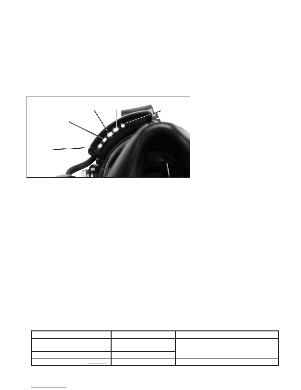
LOW BATTERY
WARNING
1/2 YELLOW
LIGHT
(FLASHING
SLOWLY)
1/4 RED
LIGHT
(FLASHING
RAPIDLY)
3/4 GREEN
LIGHT
FULL GREEN
LIGHT
FIGURE 1
HEADS-UP DISPLAY
2. After initialization, the rectangular indicator lights will show the level
of the air supply in the cylinder as follows:
a) FULL cylinder is indicated by the two green lights glowing near
the center of the display.
b) THREE-QUARTERS cylinder is indicated by a single green light
glowing.
c) ONE-HALF cylinder is indicated by the yellow light flashing slowly
at once a second.
d) ONE-QUARTER cylinder end of service time indicator is indicated
by the red light at the far left flashing rapidly at ten times a
second. WHEN THIS WARNING LIGHT IS FLASHING RAPIDLY,
THE USER MUST LEAVE THE HAZARDOUS ATMOSPHERE IMMEDIATELY.
3. When the battery requires changing, the round LOW BATTERY indicator at the right of the display will light for twenty (20) seconds
and then begin to flash slowly at once a second. When the LOW
BATTERY indicator is actuated, the battery still has sufficient life
to operate the HEADS-UP DISPLAY longer than the longest duration cylinder installed on the respirator. However, the battery must
be changed immediately upon termination of use of the respirator,
or before reentry into a hazardous atmosphere. See the BATTERY
REPLACEMENT section of this instruction.
WARNING
THE RESPIRATOR USER MUST IMMEDIATELY LEAVE THE AREA REQUIRING RESPIRATORY PROTECTION WHEN AN END OF
SERVICE INDICATOR ALARM ACTUATES.
ACTUATION OF ANY END OF SERVICE INDICATOR ALARM WARNS THAT APPROXIMATELY 25% OF FULL PRESSURE REMAINS
IN THE AIR SUPPLY CYLINDER (THAT IS,
APPROXIMATELY 3/4 OF THE TOTAL AIR
SUPPLY HAS BEEN USED) OR THAT THERE
IS A MALFUNCTION IN THE RESPIRATOR.
A DELAY IN LEAVING THE AREA AFTER
ALARM ACTUATION MAY RESULT IN SERIOUS INJURY OR DEATH.
HEADS-UP DISPLAY QUICK GUIDE
TWO LIGHTS GLOWING
ONE LIGHT GLOWING
ONE LIGHT FLASHING SLOWLY
ONE LIGHT FLASHING RAPIDLY
WHAT THEY MEANINDICATOR LIGHTS WHAT YOU SHOULD DO
FULL CYLINDER
3/4 CYLINDER
1/2 CYLINDER
1/4 CYLINDER
Page 7 of 44
CONTINUE USING RESPIRATOR
LEAVE HAZARDOUS AREA IMMEDIATELY
P/N 595236-01 Rev. B 10/11

FACEPIECE FITTING AND FIT TESTING
A respirator Quantitative Fit Test must be performed to ensure the correct
respirator facepiece size has been selected and assigned to the user. It is
the responsibility of the Respiratory Protection Program Manager or Safety
Coordinator to assist the user in selecting the correct respirator size relative
to the user’s facial features and dimensions. Fit Testing must be performed
with any approved SCOTT accessories that will be used with the respirator
installed, such as a communications device installed on the facepiece.
Respirator fit tests are explained fully in the American National Standard
Practices for Respiratory Protection, ANSI Z88.10-2001 which is published
by the American National Standards Institute (ANSI), 11 West 42nd Street,
New York, New York, 10036, and in the Occupational Safety and Health
Standards, OSHA 29 CFR 1910.134 Appendix A, which is published by the
Occupational Safety and Health Administration (OSHA), 200 Constitution
Avenue, NW, Washington DC, 20210.
Quantitative Fit Testing per OSHA Standard 29 CFR Part 1910.134 Appendix
A, or ANSI Standard Z88.10-2001 requires testing in the negative pressure
mode using equipment such as a Portacount1 Respirator Fit Tester. For
Quantitative Fit Testing, SCOTT facepieces require use of the appropriate
negative pressure testing equipment such as the Portacount Respirator Fit
Tester along with the following:
• SCOTT40mm facepieceAdapter,P/N200423-01,
• anewSCOTTP100Cartridge, P/N052683,
• SCOTTProbedFit TestAdapterP/N805628-01or equivalent probed
facepieces and the full range of sizes and styles
• MaskSealKit,P/N805655-01
• the appropriate SCOTT communication device and mounting bracket
properly installed on the facepiece, if such an accessory will be used
with the respirator.
• anyotheroptionalhood,eyeglass,orotheraccessorythatwillbeused
with the respirator.
The size and style facepiece must be selected based on the user’s measured face size. For initial fitting, carefully don the facepiece and conduct a
NEGATIVE PRESSURE LEAK TEST according to the instructions provided
with the 40mm Adapter. Refer to the DONNING PROCEDURE section of this
instruction for the procedure. Follow the DONNING PROCEDURE CARE-
FULLY. If the selected facepiece does not pass the NEGATIVE PRESSURE
LEAK TEST or does not fit securely without movement in the chin or chin
cup area or the user experiences discomfort in the chin or throat, try the
next nearest size, larger or smaller. After passing the NEGATIVE PRESSURE
LEAK TEST, the facepiece size selected must be verified by successfully
passing a respirator Quantitative Fit Test.
When fit testing for Open-Circuit, Pressure Demand Self-Contained Breathing Apparatus and/or Type C Pressure-Demand Supplied Air Respirator
mode of operation (minimum Fit Factor equal to or greater than 500
minimum) appropriate negative pressure testing equipment must be used.
You should use a P100 Filter, SCOTT P/N 052683 and the SCOTT P/N
805628-01 Fit Test Adapter.
When using a Portacount Respirator Fit Tester for Quantitative Fit Testing, TSI recommends that the level of particles in the ambient air must be
between 5000 and 30000 particles/cm3. Refer to the Portacount Respirator
Fit Tester user instructions for details including available Particle Generators to use with the Portacount Respirator Fit Tester if you have difficulty
achieving the minimum level of ambient particle count required.
Test subjects must be in good health at the time of the fit testing. Smoking
or eating less than 30 minutes prior to the test is prohibited. Any and all
conditions that might interfere with a good face to facepiece seal must be
addressed and corrected before performing the fit testing. Refer to the list
of conditions in the DONNING PROCEDURES section of this instruction.
THE USER MUST BE PROPERLY FITTED
WARNING
USING A RESPIRATOR QUANTITATIVE FIT
TEST BEFORE USE AND FOLLOW ALL
WARNINGS AND SPECIAL OR CRITICAL
USER’S INSTRUCTIONS SPECIFIED DURING USE. FAILURE TO DO SO MAY RESULT
IN SERIOUS INJURY OR DEATH.
WARNING
FIT TESTING IN ACCORDANCE WITH OSHA
STANDARD 29 CFR PART 1910 IS REQUIRED
AS PART OF THE REQUIRED TRAINING BEFORE USE OF THIS RESPIRATOR. FAILURE
TO PROPERLY FIT AND TRAIN THE USER
IN USE OF THE FACEPIECE AND RESPIRATOR MAY RESULT IN EXPOSURE TO THE
HAZARDOUS ATMOSPHERE WHICH COULD
LEAD TO SERIOUS INJURY OR DEATH.
WARNING
RESPIRATORS SHALL NOT BE WORN WHEN
CONDITIONS PREVENT A GOOD FACE SEAL.
SUCH CONDITIONS MAY INCLUDE, BUT ARE
NOT LIMITED TO, GROWTH OF BEARDS,
SIDEBURNS, FACIAL HAIR OR LOW HAIRLINE THAT CROSSES OR INTERFERES
WITH THE SEALING SURFACE, THICK OR
PROTRUDING HAIRSTYLES SUCH AS PONY
TAILS OR BUNS THAT INTERFERE WITH THE
SMOOTH AND CLOSE FIT OF THE HEAD
HARNESS TO THE HEAD, A SKULL CAP
THAT PROJECTS UNDER THE FACEPIECE,
TEMPLE PIECES ON CORRECTIVE EYE
GLASSES, EXCESSIVE USE OF COSMETICS INCLUDING MOISTURIZERS, MAKE-UP,
OR AFTER SHAVE, OR ANYTHING ELSE
WHICH INTERFERES WITH THE FACE TO
FACEPIECE SEAL. ALSO, THE ABSENCE OF
ONE OR BOTH DENTURES CAN SERIOUSLY
AFFECT THE FIT OF A FACEPIECE. USE OF
AN IMPROPERLY FITTED FACEPIECE MAY
LEAD TO EXPOSURE TO THE HAZARDOUS
ATMOSPHERE WHICH COULD RESULT IN
SERIOUS INJURY OR DEATH.
P/N 595236-01 Rev. B 10/11
Page 8 of 44

To verify the fit factor of the respirator, testing must incorporate an exercise
regimen of normal daily activities. SCOTT requires the following set of fit
test exercises, which are based on OSHA Standard 29 CFR Part 1910.134
Appendix A, and ANSI Z88.10-2001 with modifications.
Exercises are to be performed each for 60 seconds (except as noted) in
a standing position during the test:
• NormalBreathing
• Deepbreathing
• Turningheadsidetoside
• Movingheadupanddown(lookup/lookdown)
• Talking(read theRainbowPassage)
• Grimace(15seconds)
• BendingOver(touchtoes)/Reachup(toward theceiling)
• NormalBreathing(repeat)
Fit test exercises must be performed carefully as if the respirator was being
used in a hazardous atmosphere. DO NOT bump the facepiece, filter, or
adapter into the body through exaggerated motions. DO NOT talk except
when directed to by the test administrator.
SCOTT requires that users of this respirator with an approved SCOTT
facepiece, must achieve a Fit Factor of at least 500 for Type C PressureDemand Supplied Air Respirator mode of operation for use with their assigned facepiece style and size using the fit test procedures and exercise
regimen stated above. If a Fit Factor of at least 500 cannot be achieved
with any facepiece size or style, the user MUST NOT use this respirator.
If the respirator user passes a NEGATIVE PRESSURE LEAK TEST but
DOES NOT pass a respirator Quantitative Fit Test, try the next nearest
size, larger or smaller and repeat the NEGATIVE PRESSURE LEAK TEST
and the Quantitative Fit Test. If leakage is still detected, either per these
user instructions or the OSHA fit testing process, the use of Mask Seal Kit
P/N 805655-01 may be required to attain a proper fit. Refer to the INSTALLATION AND USE INSTRUCTIONS, SCOTT P/N 89462-01, included with
the Mask Seal Kit. After installing the Mask Seal Kit, repeat the fit testing
process to confirm a proper fit.
Once the proper size is selected and assigned to the user following successful Portacount Respirator Fit Tester testing to achieve minimum Fit
Factors required, the respirator user must perform and pass a NEGATIVE
PRESSURE LEAK TEST as described in these instructions every time the
facepiece is donned to ensure proper fit before using the respirator in a
hazardous atmosphere.
During NEGATIVE PRESSURE LEAK TESTING, any facepiece leakage
that is detected from other than the face to facepiece seal may indicate
damaged or defective equipment. Remove the defective equipment from
service and tag for repair by authorized personnel. Repeat the testing with
equipment known to be operating properly.
IF A SATISFACTORY NEGATIVE PRESSURE LEAK TEST CANNOT BE
PERFORMED, DO NOT USE THE RESPIRATOR OR ENTER THE HAZARDOUS ATMOSPHERE.
The facepiece alone does not provide any protection against a hazardous
atmosphere without the use of the complete respirator.
A respirator Quantitative Fit Test must be routinely carried out as outlined
above for each user of this respirator to determine or confirm the amount
of protection that the respirator provides.
Periodically repeating the fit testing is required to identify any physical
changes of the user (such as those listed in the DONNING PROCEDURES)
which could effect the fit of the facepiece.
Page 9 of 44
P/N 595236-01 Rev. B 10/11

REGULAR OPERATIONAL INSPECTION
The following procedure shall be used when you first receive the respirator and for daily or periodic inspection of the respirator. Respirators
in regular use must be inspected at the start of each use period and
during cleaning after each use. Respirators maintained for emergency
use must be inspected as frequently as required to assure the respirator
will function properly when required. The US Labor Department (OSHA),
pursuant to 29 CFR 1910.134, requires at least monthly inspection of
respirators maintained for emergency use. NIOSH recommends an
inspection for cylinder pressure at least weekly. The condition of storage at your location or the regulations which apply to your respiratory
protection program may require more frequent periodic inspections.
If the respirator is equipped with a PASS device distress alarm, the following procedures must be modified to include inspection of the PASS device.
Details of the REGULAR OPERATIONAL INSPECTION of the PASS device
are included in the user instructions for the PASS device. The part number
of the required PASS user instructions appears on the label on the battery
cover of the PASS device Sensor Module.
IF ANY DISCREPANCY OR MALFUNCTION IS NOTED DURING
THE INSPECTION, DO NOT USE THE RESPIRATOR. REMOVE
THE RESPIRATOR FROM SERVICE AND TAG IT FOR REPAIR BY
AUTHORIZED PERSONNEL.
INSPECTION OF THE BREATHING AIR CYLINDER
1. Visually inspect breathing air cylinder and valve assembly for physical
damage such as dents or gouges in metal or in composite wrapping.
Cylinders which show physical damage or exposure to high heat or
flame, such as paint turned brown or black, decals charred or missing, pressure gauge lens melted or elastomeric bumper distorted,
and cylinders which show evidence of exposure to chemicals such
as discoloration, cracks in the cylinder or the composite wrapping,
peeling of the outer layers of the composite wrapping and/or bulging
of the cylinder wall, shall be removed from service and emptied of
compressed air. Publications on compressed gas cylinder inspection
procedures are available from Compressed Gas Association Inc.,
1725 Jefferson Davis Hwy., Suite 1004, Arlington, VA 22202 (703412-0900).
2. Check the latest cylinder hydrostatic test date to ensure it is current.
The date of manufacture marked on the cylinder is also the date of
the first hydrostatic test. All breathing air cylinders used with SCOTT
AIR-PAK 75i SCBA’s must be visually inspected regularly and hy-
drostatically tested at the required intervals by a licensed cylinder
re-tester. Intervals for hydrostatic testing are established in the appropriate US Department of Transportation (DOT) specification or
applicable DOT exemption, or in the appropriate Transport Canada
(TC) Permit of Equivalent Level of Safety. Refer to the current revision
of Safety Precautions for AIR-PAK Cylinders, SCOTT P/N 89080-01,
available on request from SCOTT Safety. Composite fiber overwrapped cylinders must be tested up to their maximum life which, at
the time of the publication of this instruction, is 15 years from the date
of manufacture. It is the responsibility of your organized respiratory
protection program to arrange for visual inspection and hydrostatic
testing of cylinders by a licensed re-tester.
3. Check for damage of the cylinder valve hand wheel and the threads
on the cylinder valve outlet.
4. Check the relief valve (burst disc) for damage or dirt.
5. Check the cylinder pressure gauge for “FULL” indication. If cylinder pressure is less than “FULL,” replace with a fully charged
cylinder.
THE INFORMATION IN THIS INSTRUC-
WARNING
TION IS MEANT TO SUPPLEMENT, NOT
REPLACE, THE INSTRUCTIONS, TRAINING, SUPERVISION, MAINTENANCE, AND
OTHER ELEMENTS OF YOUR ORGANIZED
RESPIRATORY PROTECTION PROGRAM.
SEE WARNING ON SECOND PAGE OF THIS
DOCUMENT. FAILURE TO HEED ANY WARNINGS IN THIS INSTRUCTION MAY RESULT IN
SERIOUS INJURY OR DEATH.
WARNING
FOLLOW THE REGULAR OPERATIONAL
INSPECTION PROCEDURE EXACTLY. IF
THE END OF SERVICE INDICATOR ALARM
DOES NOT ACTUATE AS DESCRIBED IN
THIS INSTRUCTION, THE PURGE DOES NOT
ACTUATE AS DESCRIBED IN THIS INSTRUCTION OR ANY OTHER OPERATIONAL MALFUNCTION IS NOTED, DO NOT USE THE
RESPIRATOR. REMOVE THE RESPIRATOR
FROM SERVICE AND TAG IT FOR REPAIR
BY AUTHORIZED PERSONNEL. FAILURE
TO PROPERLY IDENTIFY MALFUNCTIONS
MAY RESULT IN SERIOUS INJURY OR
DEATH.
WARNING
IF THE RESPIRATOR IS EQUIPPED WITH
A PASS DEVICE DISTRESS ALARM AND
IT FAILS TO FUNCTION IN ACCORDANCE
WITH THE INSTRUCTIONS CONCERNING
REGULAR OPERATIONAL INSPECTION SUPPLIED WITH THE DISTRESS ALARM, DO NOT
USE THE RESPIRATOR. REMOVE IT FROM
SERVICE AND TAG FOR REPAIR BY AUTHORIZED PERSONNEL. FAILURE TO PROPERLY
IDENTIFY MALFUNCTIONS MAY RESULT IN
SERIOUS INJURY OR DEATH.
WARNING
DAMAGED CYLINDERS MAY SUDDENLY
LEAK OR RUPTURE IF LEFT CHARGED WITH
COMPRESSED AIR. FAILURE TO INSPECT
FOR DAMAGE AND TO EMPTY THE AIR
FROM DAMAGED CYLINDERS MAY RESULT
IN SERIOUS INJURY OR DEATH.
P/N 595236-01 Rev. B 10/11
Page 10 of 44

INSPECTION OF THE RESPIRATOR
If any damage is found in this inspection, remove the respirator from
service and tag for repair by authorized personnel.
1. Inspect the complete respirator for worn or damaged compo-
nents.
a) Inspect hoses and rubber parts which exhibit cracking, splitting,
or brittleness.
b) Inspect harness webbing for cuts, tears, abrasion, fraying, or
indication of heat or chemical damage.
c) Check all buckles and fasteners for proper operation.
d) Check the cylinder retention system for damage and for proper
operation.
e) Verify that the respirator has been properly cleaned.
2. Remove the breathing regulator from the facepiece by pulling back
on the regulator retaining latch and rotating the regulator ¼ turn.
Inspect the gasket on the breathing regulator that seals against the
facepiece for rips or damage that may break the seal.
3. Inspect the breathing regulator for damaged or missing components.
a) Verify that the regulator gasket is not damaged and is in place
around the outlet port of the regulator.
b) Verify that the purge valve (red knob) is not damaged and turns
smoothly one-half turn from stop to stop.
FACEPIECE INSPECTION
Examine the facepiece assembly for damaged or worn components. The
facepiece must be complete and in serviceable condition with no worn,
loose, or damaged components. Inspect the facepiece as follows:
1. Inspect the facepiece seal and other rubber components for deforma-
tion, wear, damage, or cracks.
2. Inspect the lens for cracks, gouges, scratches, or any condition that
could impair the operation of the facepiece or the user’s vision.
3. Inspect the lens frame or bezel for damage such as cracks or distor-
tion.
4. Check that all lens frame retainers or bezel screws are present and
installed correctly.
5. Check that all harness anchors are present and operating properly.
6. Inspect the head harness for correct installation with all straps oriented
correctly.
7. Inspect the head harness for damage or worn components.
8. Inspect the voicemitters for dents or damage. Verify that the voicemit-
ters are properly installed and secure in the voicemitter ducts.
RESPIRATORS MUST BE CLEANED AND
WARNING
INSPECTED BEFORE STORAGE FOR
REUSE. RESPIRATORS WITH WORN OR
DAMAGED COMPONENTS SHALL NOT BE
STORED FOR REUSE. REPLACE WORN
OR DAMAGED COMPONENTS DURING INSPECTION OR REMOVE THE RESPIRATOR
FROM SERVICE AND TAG IT FOR REPAIR
BY AUTHORIZED PERSONNEL. USE OF A
RESPIRATOR WITH WORN OR DAMAGED
COMPONENTS MAY RESULT IN SERIOUS
INJURY OR DEATH.
FIGURE 1
Checking Voicemitter Ducts
9. Inspect the nose cup for cuts or damage. Also look for any signs of
damage to the facepiece port side of the nose cup where the regulator attaches.
Check that the nose cup is properly seated between the flanges of
the voicemitter ducts. See FIGURE 1.
Page 11 of 44
REGULAR OPERATIONAL INSPECTION
CONTINUED ON NEXT PAGE...
P/N 595236-01 Rev. B 10/11

REGULAR OPERATIONAL INSPECTION CONTINUED...
10. Verify that the facepiece is clean.
11. Adjust the head straps to the full outward position.
12. All SCOTT facepieces used with this respirator may be fitted with a
nose cup. Verify that the Nose Cup is properly installed for the model
of facepiece being used. A Nose Cup is standard on the SCOTT AV2000 and AV-3000 full facepieces and optional on the SCOTT-O-VISTA
full facepiece.
a) SCOTT AV-3000 Facepieces are available with two different styles
of nose cup: a BLACK Nose Cup which fits behind the face seal,
and a GRAY Nose Cup which fits in front of the face seal. The
BLACK Nose cup must be fitted BEHIND the Face Seal as shown
in FIGURE 2. The GRAY Nose Cup must be fitted IN FRONT OF
the Face Seal as shown in FIGURE 3.
AV-3000 FACEPIECES ONLY
GRAY
IN FRONT
OF FACE
SEAL
BLACK
BEHIND
FACE
SEAL
FIGURE 2
BLACK Nose Cup
BEHIND Face Seal
b) The AV-2000 Nose Cup always goes BEHIND the face seal RE-
GARDLESS of the color of the nose cup. See FIGURE 4.
IN FRONT OF Face Seal
FIGURE 3
GRAY Nose Cup
IF THE NOSE CUP IS REMOVED FOR INSPEC-
CAUTION
TION, MAKE CERTAIN IT IS REASSEMBLED
CORRECTLY FOR THE MODEL FACEPIECE
AND STYLE OF NOSE CUP.
CAUTION
DO NOT USE TOOLS TO OPEN OR CLOSE
THE PURGE VALVE. OPEN OR CLOSE BY
USING FINGER-PRESSURE ONLY. ROTATION
OR THE PURGE VALVE IS LIMITED TO 1/2
TURN. USE OF TOOLS TO OPEN OR CLOSE
PURGE VALVE MAY RESULT IN DAMAGE TO
THE PURGE VALVE.
AV-2000 FACEPIECES ONLY
FIGURE 4
AV-2000 Nose Cup
Always BEHIND the Face Seal
P/N 595236-01 Rev. B 10/11
Page 12 of 44
5. If the hose to the breathing regulator is equipped with a quick dis-
connect, inspect both the male and female quick disconnects. Pay
special attention to the following:
a) Inspect the operation of the locking sleeve on the female quick
disconnect. If any damage is noted, remove it from service and
tag for repair.
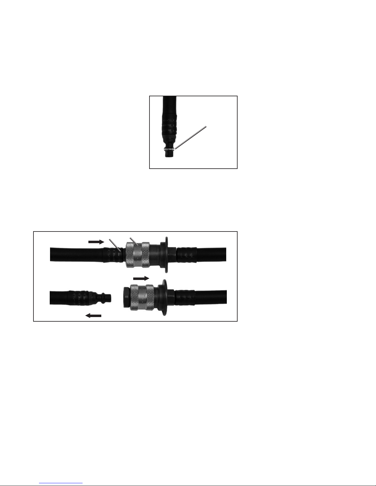
b) Inspect the condition of the male quick disconnect for signs of
wear. Particularly look for wear on the locking ridge as shown in
FIGURE 5. If the coating is worn through and bare metal is showing, do not use the regulator assembly. Remove it from service
and tag for replacement.
LOOK FOR WEAR
ON LOCKING
RIDGE
FIGURE 5
Inspecting Male
Quick Disconnects
6. Verify that the quick disconnect operates properly. Breathing regu-
lators equipped with a quick disconnect use a Pull-back Sleeve
Coupling. See FIGURE 6. To separate, push the plug “D” into the
socket while pulling the locking sleeve “E” back toward the guard.
The plug “D” will separate. To connect, push the plug "D" into the
socket until it engages with a "click."
7. If the regulator is not attached to the facepiece, proceed as
follows:
PUSH PLUG IN
D
E
WARNING
IF THE COATING IS WORN THROUGH AND
BARE METAL IS SHOWING ON THE MALE
QUICK DISCONNECT LOCKING RIDGE, REMOVE THE REGULATOR ASSEMBLY FROM
SERVICE AND TAG FOR REPLACEMENT.
USE OF A WORN QUICK DISCONNECT MAY
RESULT IN A MALFUNCTION LEADING TO
A LOSS OF BREATHING AIR WHICH COULD
RESULT IN SERIOUS INJURY OR DEATH.
WARNING
FAILURE TO CHECK ENGAGEMENT OF THE
COUPLING AS DESCRIBED MAY LEAD TO
HOSE SEPARATION AND LOSS OF BREATHING AIR RESULTING IN SERIOUS INJURY
OR DEATH.
PULL SLEEVE
BACK
PULL PLUG OUT
FIGURE 6
Pull-back Sleeve Quick Disconnect
a) Align the two flats of the regulator outlet port with the correspond-
ing flats in the facepiece port (the red purge valve on the regulator will be in the 12 o’clock position). Insert the regulator into the
facepiece port.
b) Rotate the regulator counterclockwise (as viewed from inside of
facepiece) until the red purge valve knob is on the left side of the
facepiece. The lock tab on the regulator will lock into the facepiece
retainer with a “click.” When the lock tab is properly engaged, the
regulator will not rotate.
8. If the hose to the breathing regulator is equipped with a quick
disconnect, check that the quick disconnect is engaged properly
by tugging on the coupling.
9. Verify that a FULL cylinder is properly installed in the backframe
and that the reducer hose coupling is hand tightened to the cylinder valve outlet.
If no damage is found, proceed to the OPERATIONAL TESTING.
Page 13 of 44
WRENCHES SHALL NOT BE USED TO TIGHT-
CAUTION
EN THE HOSE COUPLING. OVER TIGHTENING THE HOSE COUPLING MAY DAMAGE
THE GASKET SEAL.
REGULAR OPERATIONAL
INSPECTION CONTINUED
ON NEXT PAGE...
P/N 595236-01 Rev. B 10/11

REGULAR OPERATIONAL INSPECTION CONTINUED...
OPERATIONAL TESTING
1. Check that the breathing regulator purge valve (red knob on regulator) is closed (full clockwise and pointer on knob upward).
2. Fully depress the center of the air saver/donning switch on the top
of the regulator and release.
3. Slowly open the cylinder valve by fully rotating the knob counterclockwise.
a) VIBRALERT alarm shall actuate and then stop.
b) The optional HEADS-UP DISPLAY will initialize with all five lights
on for twenty seconds followed by display of cylinder supply level.
If the LOW BATTERY light at the far right of the display remains lit
or begins to flash, replace the batteries according to the BATTERY
REPLACEMENT section of this instruction before proceeding.
c) If the respirator is equipped with the PASS device distress alarm,
the distress alarm will be actuated when the cylinder valve is
opened. Refer to Operating and Maintenance instructions of the
PASS device distress alarm for the regular operational inspection
of the PASS device distress alarm.
4. Check that the remote pressure gauge is operating properly and that
it reads within 10% of the value on the cylinder pressure gauge.
5. Don the facepiece or hold the facepiece to the face to affect a good
seal. Inhale sharply to automatically start the flow of air. Breathe
normally from the facepiece to ensure proper operation.
6. Removefacepiecefromface.Airshallfreelyowfromthefacepiece.
7. Fully depress the air saver/donning switch on the top of regulator
and release. The flow of air from the facepiece shall stop. Examine
the complete respirator for air leaks. There shall be no leakage of
air from any part of the respirator.
8. Check the purge valve:
a) Rotate purge valve 1/2 turn counterclockwise (pointer on knob
downward). Air shall freely flow from the regulator.
b) Rotate purge valve 1/2 turn clockwise to full closed position (pointer
on knob upward). Air flow from regulator shall stop.
WARNING
IF THE END OF SERVICE INDICATOR ALARM
DOES NOT ACTUATE AS DESCRIBED IN
THIS INSTRUCTION, DO NOT USE THE
RESPIRATOR. REMOVE THE RESPIRATOR
FROM SERVICE AND TAG IT FOR REPAIR
BY AUTHORIZED PERSONNEL. USE OF AN
IMPROPERLY OPERATING END OF SERVICE INDICATOR MAY RESULT IN SERIOUS INJURY OR DEATH.
WARNING
IF THE RESPIRATOR IS EQUIPPED WITH
A PASS DEVICE DISTRESS ALARM AND
IT FAILS TO FUNCTION IN ACCORDANCE
WITH THE INSTRUCTIONS CONCERNING
REGULAR OPERATIONAL INSPECTION SUPPLIED WITH THE DISTRESS ALARM, DO NOT
USE THE RESPIRATOR. REMOVE IT FROM
SERVICE AND TAG FOR REPAIR BY AUTHORIZED PERSONNEL. FAILURE TO PROPERLY
IDENTIFY MALFUNCTIONS MAY RESULT IN
SERIOUS INJURY OR DEATH.
P/N 595236-01 Rev. B 10/11
Page 14 of 44
 Loading...