

Page 1

A2
MP3/WMA/SD/USB/AUX CAR RADIO
FM Stereo/MW Radio
RDS (Radio Data System) Function
4x25 W High Power Output
BAND
CLK
1 2 INT 3 RPT 4 RDM 5 -10 6 +10
AUX
SD
MUTE
PWR
VOL+
VOL
SEL
TA
MODE AFPTY
A
S/PS
USER MANUAL
Page 2

GB-1
CONTENTS
CONTENTS.................................................................................................................................................................................. GB-1
ACCESSORIES............................................................................................................................................................................GB-2
PRECAUTION ..............................................................................................................................................................................GB-3
INSTALLATION ............................................................................................................................................................................GB-4
USING THE DETACHABLE FRONT PANEL ............................................................................................................................... GB-6
WIRING DIAGRAM ......................................................................................................................................................................GB-7
LOCATION AND FUNCTION OF KEYS....................................................................................................................................... GB-8
GENERAL OPERATIONS ......................................................................................................................................................... ..GB-9
RADIO OPERATIONS............................................................................................................................................................... GB-12
RDS (RADIO DATA SYSTEM) OPERATIONS.......................................................................................................................... GB-14
USB, SD/MMC CARD OPERATIONS ....................................................................................................................................... GB-15
MP3/WMA FILE OPERATIONS ................................................................................................................................................ GB-16
AUX IN OPERATIONS .............................................................................................................................................................. GB-18
SPECIFICATIONS..................................................................................................................................................................... GB-18
TROUBLESHOOTING............................................................................................................................................................... GB-19
Page 3
GB-2
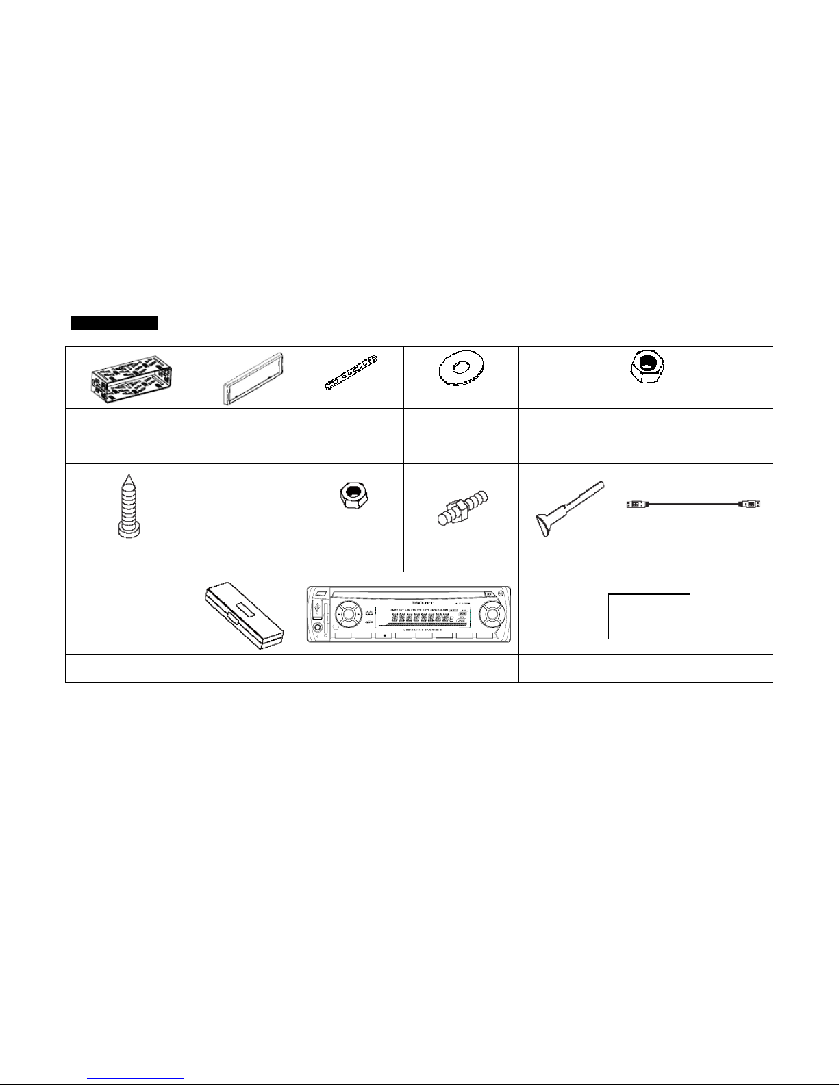
ACCESSORIES
Mounting Bracket
(Half Sleeve)
X1
Removable Trim
Ring equipped on
the unit
X1
Small metal Strip
X1
Plain Washer
X2
Spring Washer
X1
Tapping Screw
X1
Hex Nut
X1
Mounting Bolt
X1
Release Key
X2
USB Adaptor Cable
X1
BAND
CLK
1 2 INT 3 RPT 4 RDM 5 -10 6 +10
AUX
SD
MUTE
PWR
VOL+
VOL
SEL
TA
MODE AFPTY
AS/PS
Protective Case
X1
Removable Control Panel
X1
User Manual
X1
Page 4

GB-3
PRECAUTION
This unit is designed and manufactured with the user’s safety in mind, however any improper use or operation may result in certain
dangers. It is therefore highly recommended to read this manual thoroughly and adhere to the following precautions.
SAFETY PRECAUTIONS
To prevent an electrical shock, do not open the housing of the unit. In any case of malfunctioning, only have the unit serviced by an
approved and qualified service centre.
Do not expose to any water or to a very humid environment. Do not operate the unit when your hands are wet as this may cause a
short circuit.
For safe driving, keep the volume low in order to concentrate on traffic conditions.
Do not clean the unit with alcohol, only clean with a soft dry cloth.
If the unit has been kept at a high temperature or in a high humidity environment, cool down the car interior before turning on the
unit.
Do not use the unit for a long time without running the vehicle engine, it may drain the battery and the vehicle engine may not be
able to start.
Before final installation in the dashboard opening, first connect the wiring and make sure the unit is working properly.
Only use parts provided with the unit to ensure proper installation.
Do not route wiring in places that the heat may melt the wiring insulation.
When replacing the fuse, ensure that the new fuse has the capacity recommended by the manufacturer.
OPERATION PRECAUTIONS
Never insert any other objects into the USB port or card slot, such as a coin or pin, etc as this may cause damage or a short circuit.
If the unit is disconnected to the battery, it will lose memorized data.
Page 5
GB-4
INSTALLATION
Notes:
- Choose the mounting location where the unit will not interfere with the normal driving function of the driver.
- Before finally installing the unit, connect the wiring and make sure that the unit works properly.
- Consult your dealer if installation requires the drilling of holes or other modifications of the vehicle.
- Install the unit where it does not get in the driver's way and cannot injure the passenger if there is a sudden stop, like an
emergency stop.
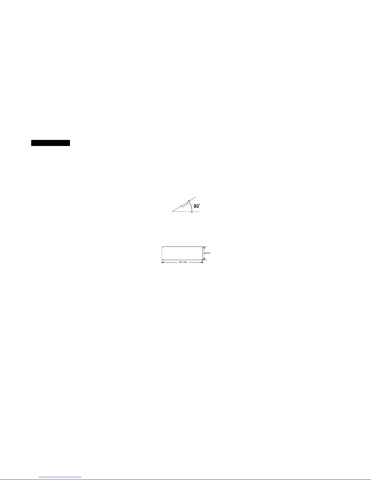
- If installation angle exceeds 30°from horizontal, the unit may not perform properly.
- Avoid installing the unit where it would be subject to high temperatures, such as from direct sunlight, hot air, or a heater.
Installation Opening
This unit can be installed in any dashboard having an opening as shown below (DIN standard):
Installing the unit
Be sure you test all connections first, and then follow these steps to install the unit.
1. Make sure the ignition is turned off, and then disconnect the cable from the vehicle battery's negative (-) terminal.
2. Disconnect the wire harness and the antenna.
3. Press the OPEN (REL) button to remove the control panel (For details, refer to 'USING THE DETACHABLE FRONT PANEL').
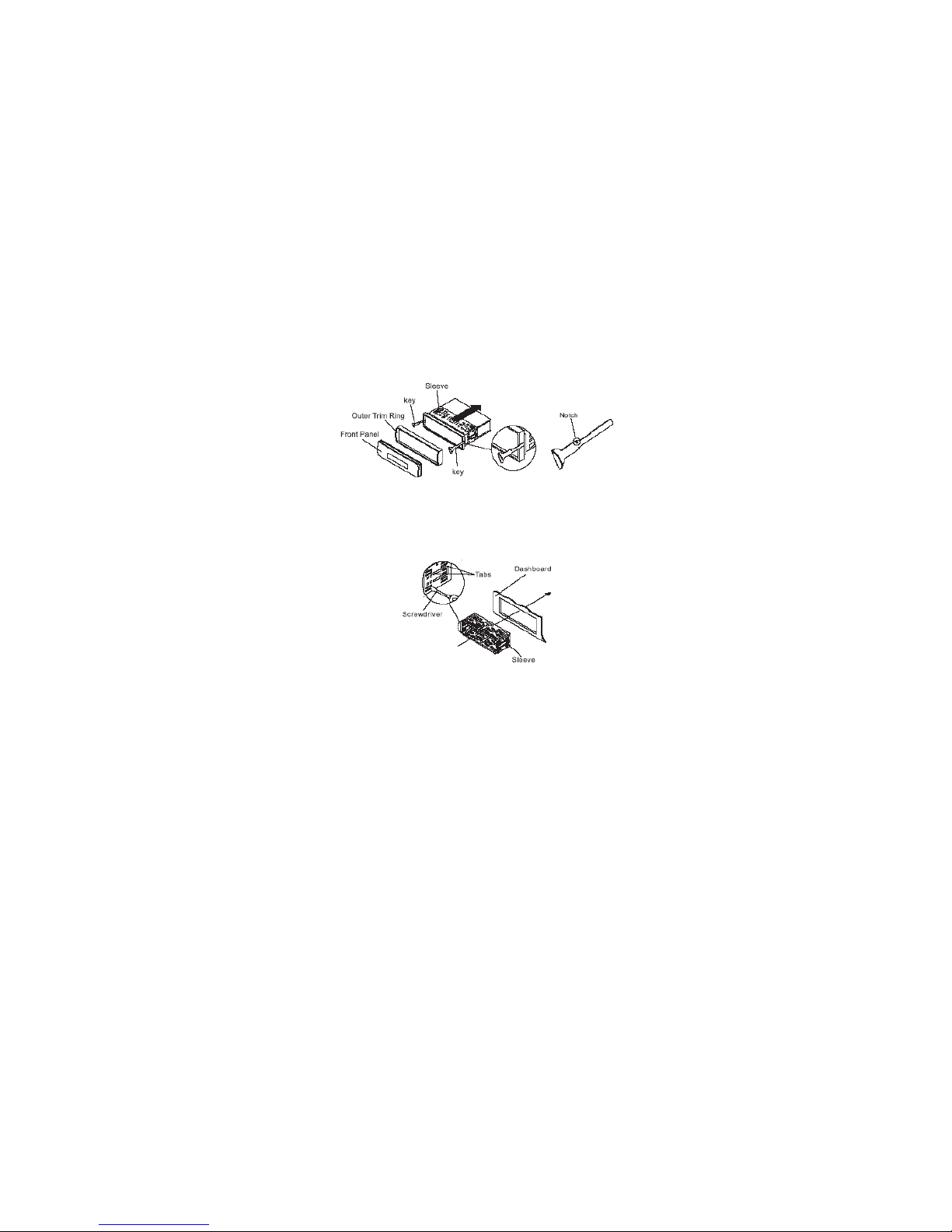
4. Remove the trim ring by pulling it gently out.
5. Use the two supplied release keys to remove the unit from the mounting bracket. Insert the left and right release keys as far as
they will go (with the notches facing up) into the appropriate slots at the middle left and right sides of the unit.
Then slide the sleeve off the back.
Page 6
GB-5
6. Mount the sleeve by inserting the sleeve into the opening of the dashboard and bend out the tabs located around the sleeve with
a screwdriver. Not all tabs will be able to make contact, so examine which ones will be most effective. To secure the sleeve in place,
bend out the appropriate tabs so that they make contact with the dashboard.
7. Reconnect the wire harness and the antenna and be careful not to pinch any wires or cables.
8. If necessary, use the supplied metal strap to secure the back of the unit in place. Use the supplied hardware (Hex Nut (M5mm)
and Spring Washer) to attach one end of the strap to the mounting bolt on the back of the unit. If necessary, bend the metal strap to
fit your vehicle's mounting area. Then use the supplied hardware (Tapping Screw (M5x25mm) and Plain Washer) to attach the other
end of metal strap to a solid metal part of the vehicle under the dashboard.
This metal strap also helps ensure proper electrical grounding of the unit.
9. Slide the unit into the sleeve until it locks into place.
If necessary, fasten the end of the mounting bolt with the short thread to the back of the unit and the end with the long thread to the
dashboard.
Page 7

GB-6
10. Reconnect the cable to the vehicle battery's negative (-) terminal. Then replace the outer trim ring and install the unit's front
panel (see the steps of 'TO ATTACH THE FRONT PANEL').
Dismantling the unit
1. Make sure the ignition is turned off, and then disconnect the cable from the vehicle battery's negative (-) terminal.
2. Press the OPEN (REL) button to remove the front panel.
3. Remove the outer trim ring by pulling it out.
4. Insert both of the supplied keys into the slots at the middle left and right sides of the unit then pull the unit out of the dashboard.
5. Remove the metal strap attached to the back of the unit (if attached).
USING THE DETACHABLE FRONT PANEL
REMOVING AND PROTECTING DETACHABLE FRONT PANEL
The front panel of the unit may be removed as a theft deterrent. After removing the front panel, use the case provided to keep the
front panel from getting damaged.
Page 8

GB-7
1. Press the OPEN (REL) button (4) to open the front panel.
2. Grasp the right side of the front panel, then gently push the front panel towards the left side before pulling it out from the unit.
3. Store the front panel in the protective case provided for safe keeping.
TO ATTACH THE FRONT PANEL
Hold the right side of the front panel with the plate facing front.
First attach the left side of the front panel to the unit by inserting the left holder into the hole.
Then slightly push it to the left and attach the right side hole into the right holder. Finally push the front panel.
WIRING DIAGRAM
ISO connector (not supplied):
Part A:
A1: No Connect
A2: No Connect
A3: No Connect
A4: Battery B+ (Yellow)
A5: Antenna (Blue)
A6: No Connect
A7: Accessory (12V, To Ignition
Key) (Red)
A8: Ground B- (Black)
Part B:
B1: Rear Right + (Violet)
B2: Rear Right - (Violet/Black)
B3: Front Right + (Grey)
B4: Front Right - (Grey/Black)
B5: Front Left + (White)
B6: Front Left - (White/Black)
B7: Rear Left + (Green)
B8: Rear Left - (Green/Black)
Red RCA connector to rear right
White RCA connector to rear left
Red RCA connector to front right
White RCA connector to front left
A
NTENNA Socket
ISO Connector
FUSE 10A
Page 9

GB-8
Location and Function of Keys
Front panel:
The front facet after removing the front panel:
Description of Function Controls
(1) Power on/off (MUTE) Button
(2) LCD display
(3) SEL (Select) button
(4) Open (REL) Button
(5) Volume +/- Button
(6) SD/MMC Memory Card Slot
(7) USB Port
(8) MODE Button
(9) CLK (Clock) Button
(10) Anti-theft LED indicator
(11) RESET Button
(12) BAND Button (select a frequency band)
(13) Preset Station (1-6) Buttons
(14) AS/PS (Auto-storage /Preset memory Scan)
(15) UP () Button
Tune up, Seek up,track up, fast forward
(16) DOWN () Button
Tune down, Seek down,track down, fast reverse
(17) AF/(REGION) Button
(18) TA Button
(19) PTY Button
(20) INT (Introduction)/ 2 Button
(21) (Play/Pause)/1 Button
(22) SCN (Scan) Button
(23) RPT (Repeat) / 3 Button
(24) RDM (Random) / 4 Button
(25) -10/ 5 Button
(26) +10 / 6 Button
(27) AUX Input Jack
Page 10

GB-9
GENERAL OPERATIONS
Reset the unit
When operating the unit for the first time, after replacing the car battery or changing the connections, you must reset the unit.
1. Turn off the unit power.
2. Press the (REL) button and remove the front panel, then press the RESET button with a ballpoint pen or similar object to restore
the unit to the original factory settings.
Power on/off, Mute
In power off mode, switch on the unit by pressing any button except the REL button. When the system is on, press and hold the
PWR (MUTE) button to turn off the unit. Press it to mute or resume the sound.
Volume control
Press the VOL +/- button to adjust the volume.
Sound adjustment
Press the SEL button repeatedly to select the sound setting that you would like to adjust: volume, bass, treble, balance or fader.
Use the VOL +/- button to adjust the level of the selected sound mode:
- VOL: from 00 to 47
- BASS / TRE (treble): from -7 to +07
- BAL (Balance): 0LR9, 1LR9,....9LR9,..., 9LR1, 9LR0. Note: L = left, R = right.
- FAD (Fader): 0FR9, 1FR9,...9FR9,..., 9FR1, 9FR0. Note: F=front; R= rear.
Note:
When the unit has not been adjusted for about 5 seconds, the current setting will be saved and it will return to the previous mode.
System setup menu
Press the SEL button and hold for more than 2 seconds to access the system setup menu mode, then press the SEL button to
select the menu item in sequence as follows:
Page 11

GB-10
“TA SEEK or TA ALM” ¼ “PI SOUND or PI MUTE” ¼ “RETUNE L or RETUNE S” ¼ “MASK DPI or MASK ALL” ¼ “BEEP ON,
BEEP OFF" ¼ USER SET (FLAT/CLASSIC/ROCK/POP) ¼ VOL LAST/VOL DEFA ¼ STEREO/MONO (in Radio mode) ¼ LOUD
OFF/LOUD ON ¼ DX/LOCAL (in Radio mode) ¼ CLK ON/CLK OFF ¼ CLK 12/24 display.
After selecting the desired menu item, press the VOL +/-t button to make the adjustment.
“TA SEEK or TA ALARM” (search for traffic announcement/traffic announcement alarm)
- TA SEEK (traffic announcement search) mode:
When a newly tuned station does not receive traffic information for 5 seconds, the radio retunes to next station which has a different
PI and which broadcasts traffic information.
If, during the chosen retune time (90 seconds for a short retune or 150 seconds for a long retune), the unit can no longer receive the
current station which was broadcasting traffic information, it will start to search for the next station that has the same PI. If no station
with the same PI is found after one search cycle, the radio will search for the next station broadcasting traffic announcements.
- TA ALM (ALARM) mode:
Select this mode to switch off the automatic retune. The radio will then emit a double beep sound (ALARM).
If a newly tuned station does not broadcast any traffic information for 5 seconds, a beep can be heard.
If the unit can no longer receive the current station during the chosen retune time, a beep sound can also be heard.
If a newly tuned station has no RDS signal, the message “PI SEEK” disappears.
Note: TP: Traffic Program.
PI: Program Identification.
“PI SOUND or PI MUTE”:
In some regions, there is a possibility of having two different stations with the same frequency but different PI codes.
If “PI SOUND” is selected, radio will switch to the new station with a different PI for a few seconds before switching back to the
current station that was broadcast initially.
If “PI MUTE” is selected, the radio will not broadcast the new station that is received.
“RETUNE L or RETUNE S” (long/short retune):
This function allows you to set the duration after which the automatic search for traffic information or a station with an identical PI
should be carried out.
- RETUNE L mode: The automatic search will take place after 150 seconds.
- RETUNE S mode: The automatic search will take place after 90 seconds.
“MASK DPI or MASK ALL”:
Page 12

GB-11
Any alternative frequency (AF) with a different PI or which does not broadcast an RDS signal that is strong enough will normally be
masked when the PI is checked while the unit searches for an alternative frequency. The unit will not automatically go to this type of
alternative frequency. It is possible that an AF which does not broadcast a strong enough RDS signal is a valid AF, but that the car
radio wrongly considers it as a station with a different PI due to interference. For this reason, the unit offers the user an option
(MASK DPI) which does not mask the AFs which do not broadcast a strong RDS signal.
- MASK DPI mode:
Only masks the alternative frequencies with a different PI.
- MASK ALL mode:
Masks alternative frequencies with a strong signal that have a different PI or which do not emit a strong enough RDS signal.
"BEEPS ON”, “BEEP OFF”
- Beep on mode: The beep sound is on when any key is pressed.
- Beep off mode: The beep sound is disabled.
USER SET
The car audio device is equipped with 4 preset equalizer modes. “FLAT" ¼ “CLASSIC” ¼ “ROCK” ¼ “POP”.
VOL LAST/VOL DEFA
VOL LAST: Last volume before switching off is resumed at power on mode.
VOL DEFA: Set a volume at power on mode.
STEREO/MONO (FM radio mode)
STEREO: Stereo sound.
MONO: Mono sound. Select this option when the station is weak and sound distortion happens.
LOUD OFF/LOUD ON (Loudness ON/OFF)
Turn the loudness function on or off.
DX/LOCAL (in Radio mode)
In urban areas, most stations are strong enough and “LOCAL” mode should be selected. Switch to “DX” mode to search for stations
with weaker signals.
Page 13

GB-12
CLK ON/CLK OFF
CLK ON: Time is always displayed at power off mode.
CLK OFF: Time is not displayed at power off mode.
CLK 12/24 display
Select 12 or 24 time display.
To select playback mode
In power on mode, press MODE button repeatedly to select the different modes in the following sequence: TUNER, USB (with USB
device inserted), CARD (with SD/MMC card inserted), AUX in mode.
Last position memory feature
- During USB, SD/MMC card playback, if you turn off the unit and then switch on it or switch back from other mode, the unit will
resume playing from the point that it was interrupted.
CLOCK DISPLAY
Press the CLK button to display the time for 5 seconds. Press and hold it to enter time setting mode and then adjust the hour and
minute using the VOL – and VOL + buttons respectively.
Anti-theft LED Indicator
Designed as a theft deterrent, the red LED will flash when the unit is turned off and the front panel is removed.
RADIO OPERATIONS
Press the MODE button to select the TUNER mode.
To select a radio band
In radio mode, Press the BAND button repeatedly to select the radio broadcasting bands required: ->FM1-> FM2 -> FM3 -> MW1 ->
MW2.
Auto/ Manual tuning (in 50KHz steps)
- Automatic search mode:
Page 14

GB-13
Press and hold the or button to launch the automatic search forwards or backwards.The radio will search up or down for a
strong signal radio station within the current band..
- Manual search mode:
Press the or button repeatedly to manually search upward or downward step by step for the desired radio station within the
current band. Alternatively, press the SCN button to search for a station. The station frequency will blink for 5 seconds and you can
press the button again to stop scanning and listen to that station. Or otherwise, scanning will continue.
To store / recall a preset radio stations
You can store up to a total of 30 radio stations in the memory (18 FM + 12 AM), manually or automatically.
- To store a station:
- Select a band (if needed)
- Select a station by or buttons(see previous paragraph).
- Hold a Preset button (1-6) for at least 2 seconds.
- To recall a station:
- Select a band (if needed).
- Press a preset button (1-6) briefly to recall the stored station.
Note: In RDS mode, the AF function allows you to choose the frequency with the best signal for a station..
Auto store / Preset scan
- Auto store:
Press the AS/PS button for more than 2 seconds to start auto store. The radio will scan from the lowest frequency, and
automatically store the 6 strongest stations into the preset memories. When auto store is complete, the radio will start a preset scan
of the 6 stations which it has just stored.
- Preset scan:
Briefly press the AS/PS button to scan each preset station. Press AS/PS again to stop on the required station. During this process,
the number of the current station will flash on the LCD screen.
Page 15

GB-14
RDS (RADIO DATA SYSTEM) OPERATIONS
The RDS data are the PI, PS, TP, PTY, TA and AF data.
PI (Program identification): Code for identifying the radio station.
PS (Program service): Name of the radio station.
PTY (Program type): Type of program such as news, Pop music, sports etc.
TP (Traffic program): Code indicating a station broadcasting traffic information.
TA (Traffic announcement): Function allowing the broadcasting of traffic information.
AF (Alternative frequencies): Function allowing an automatic search for the best alternative frequency available.
SETTING AF MODE
Briefly press the AF button to switch AF mode on or off.
When AF is switched on, “AF” appears on the LCD display.
If the reception becomes bad, “AF” will blink and the tuner will return to alternative frequencies.
Regional Program Operation
Press the AF button for 2 seconds to switch the region mode on or off.
Some broadcasting stations change their program from normal broadcasting to regional broadcasting for a certain time period.
When region is on, the unit will receive regional broadcasts.
Using PTY to select a program
The PTY function allows you to search for a particular program type. To select a program type, press the PTY button. “POP M” (pop
music) or “NEWS” will appear on the LCD display. You can then select a program type using the preset buttons 1 to 6. The program
types are divided into two groups: the music PTY group and the speech PTY group:
HINT:
When you choose MUSIC PTY GROUP, the preset number buttons 1-6 correspond to the following programs:
Preset number Music PTY Group
1.
2.
3.
4.
5.
POP M, ROCK M
EASY M, LIGHT M
CLASSICS, OTHER M
JAZZ, COUNTRY
NATION M (national music), OLDIES
Page 16

GB-15
6. FOLK M
When you select the SPEECH PTY GROUP, the preset numbered buttons is shared as follows:
Preset number Speech PTY Group
1.
2.
3.
4.
5.
6.
NEWS, AFFAIRS, INFO
SPORT, EDUCATE, DRAMA
CULTURE, SCIENCE, VARIED
WEATHER, FINANCE, CHILDREN
SOCIAL, RELIGION, PHONE IN
TRAVEL, LEISURE, DOCUMENT
When you select a program type, the tuner will search for a station broadcasting this type of program. The tuner will stop searching
if it finds the relevant program type. If the radio does not find a station broadcasting the type of program selected, the text “PTY
NONE” is displayed for 5 seconds and the previous station is broadcast.
Listening to Traffic Announcement
It is possible to program the car radio so that it interrupts radio mode, AUX mode or the current radio station when a traffic
announcement is broadcast.
Briefly press the TA button to switch TA mode on or off. When TA mode is on, the unit automatically broadcasts available traffic
announcements. To interrupt a traffic announcement without switching off the TA mode, briefly press the TA button. The radio will
then return to the previous operating mode.If the current volume level is below 20, it will be increased to 20 during traffic
announcement and resume to previous volume level after the traffic announcement.
USB, SD/MMC CARD OPERATIONS
Using the USB stick/SD/MMC card:
When you insert a USB stick through the USB port or SD/MMC card through the card slot, the unit will search for the MP3/WMA
files and start to play them automatically. When both USB and card are inserted, press the MODE button to select the mode.
Note:
Page 17

GB-16
- Use the USB adaptor cable, if necessary.
- When reading the USB stick or card, please don't touch or remove it.
- If following the instruction above, the unit can't read the file in the USB stick or card, please check if the device is in good condition,
or take it out then insert it into the USB port or card slot once more.
- The main unit can only support the standard USB-memory device.
- USB MP3 player is not a standard which means different brand name or different models have their own standard. So this product
cannot support all MP3 players.
- When connecting an MP3 player and there is a normal battery in the player (non rechargeable battery), you should remove the
battery from the MP3 player and then connect it to the USB port. Otherwise, it may cause battery burst.
MP3/WMA FILE OPERATIONS
Playing/Pausing
- During playback, press the button to interrupt the playback. Press again to resume the playback.
Playing the previous/ next track
- During playback, press the button to play the next track.
- During playback, press the button to play the previous track..
Playing forward and backward
During playback, press and hold the or button to fast forward or fast reverse. Release the buttons when the desired location is
found, and normal playback starts.
Skip 10 tracks forward/back
During MP3/WMA playback, press 5 or 6 to skip 10 tracks forward or back.
Introduction playback
You can play the beginning of every track for 10 seconds in sequence.
In MP3/WMA file playback, briefly press the INT button to play the first 10 seconds of each track. Press it again to stop scanning
and play the current track.
Repeat playback
Page 18

GB-17
In MP3/WMA files playback, briefly press the RPT button to continuously play the current track. “RPT ONE” is displayed. Press it
again to play all of the tracks in the current folder repeatedly. “RPT ABM” is displayed. Press again to stop repeat playback and
resume normal playback.
Random playback
In MP3/WMA file playback, briefly press the RDM button to play all tracks of the disc in random sequence. Press again to cancel
random playing.
How to select a file in MP3/WMA mode:-
There are three ways to access a file in MP3/WMA mode:
Searching by track number:
a) Press the AS/PS button once to access the track number search mode. The message “TRK 00” will be shown on the LCD
display and the first digit “0” symbol will blink.
b) Press the VOL+/- button to select a number. Then press the SEL button to confirm and the second digit will flash. Press the
VOL+/- button to select a number.
Then press the SEL button to confirm and play the selected file.
.
Searching by file name:
a) Press the AS/PS button twice, the “A--SEARCH” symbol will beon the LCD display. “A” is the first character of the file name.
b) Press the VOL+/- button to select the character. The following characters are available: “A” to “Z”, “0” to “9”. The file name with
selected first character will be displayed. Use the or button to go to previous/next file with the same selected first character.
Press the SEL button to confirm.
Searching in the root directory
a) Press the AS/PS button three times to access the root directory. The first directory name is shown on the LCD display.
b) Press the VOL +/- button to navigate through the directory list. If there is no root directory in the USB or SD/MMC card, the LCD
will display “ROOT”.
c) Press the or button to select a file, then press the SEL button to confirm.
Page 19

GB-18
AUX IN OPERATIONS
This system has an external input jack, so you can listen to music from external devices connected to this unit. Press the MODE
button to switch to the AUX mode.
SPECIFICATIONS
1. GENERAL
Power Supply Requirements .......................................................................................... DC 12 Volts, Negative Ground
Unit Dimensions ............................................................................................................. 178(W)x102(D)x 50(H) mm
Tone Controls ................................................................................................................. - Bass (at 100 Hz) ±5 dB
....................................................................................................................................... - Treble (at 10 KHz) ±5 dB
Maximum Output Power ................................................................................................. 4x40 watts
Nominal Output Power ................................................................................................... 4 x20 watts (r.m.s.)
Power consumption ........................................................................................................ 10 Ampere (max.)
2. RADIO
FM
Frequency Range ........................................................................................................... 87.5 - 108 0 MHz
IF .................................................................................................................................... 10.7 MHz
Sensitivity (S/N=30dB).................................................................................................... 3μV
S/N ratio.......................................................................................................................... 55dB(mono)
Stereo separation ........................................................................................................... 30 dB (65dBu, 1KHz)
MW
Frequency Range ........................................................................................................... 522 - 1620 kHz
IF .................................................................................................................................... 450 kHz
Sensitivity ....................................................................................................................... 40dB
S/N ratio.......................................................................................................................... 40dB
3.USB/SD/MMC card
USB Port type................................................................................................................. 2.0
USB Port Maximum Handling Capacity .......................................................................... 16GB
SD/MMC Card Slot Maximum Handling Capacity........................................................... 16GB
C NOTES
Page 20

GB-19
TROUBLESHOOTING
Symptom Cause Solution
The car ignition switch is not on. Turn the ignition key to “ACCESSORY” in
order to switch the unit on.
The connections are not correct. Check the connections.
A fuse has blown in the vehicle.
No power
The fuse at the back of unit has been blown.
Check the vehicle fuses.
Volume is in minimum. Adjust volume to a desired level. No sound
The wiring is not properly connected. Check wiring connection.
The installation angle is more than 30°. Adjust the installation angle less than 30°. Sound skips
1. The built-in micro-processor is not operating
properly due to electrical noise.
1. Press the RESET button. The operation keys do not work
2. The front panel is not properly installed. 2. Fix the front panel into its place.
No radio reception The antenna cable is not connected. Insert the antenna cable firmly into the
antenna socket of this player.
In automatic search mode the radio
does not stop at a transmitting
station.
The transmission signals are too weak. Select a radio station manually.
Check the antenna connection.
If at any time in the future you want to dispose of this product, please note that electrical product should not be
disposed of with household waste. Find out where your nearest recycling centre is. Check your local authority or
retailer for more details. (Waste Electrical and Electronic Equipment Directive)
 Loading...