How it Works
Log In / Sign Up
Buy Points
How it Works
FAQ
Contact Us
Questions and Suggestions
Users
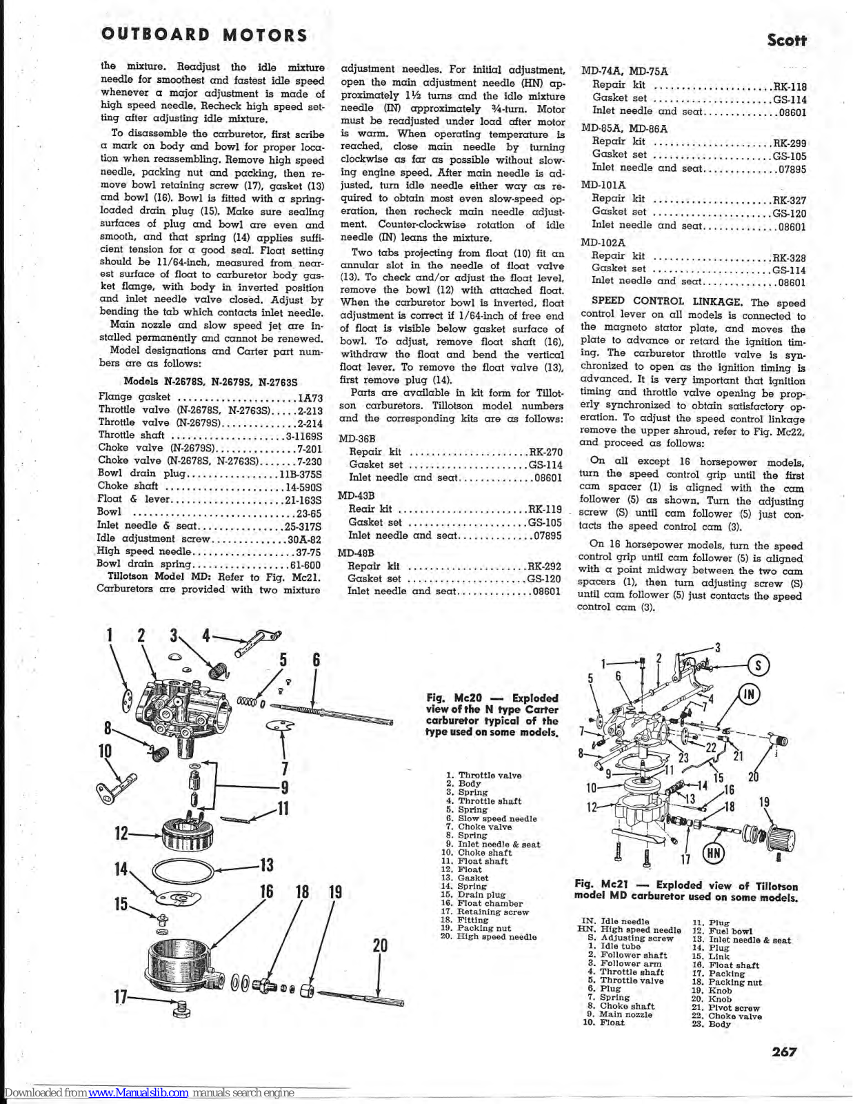
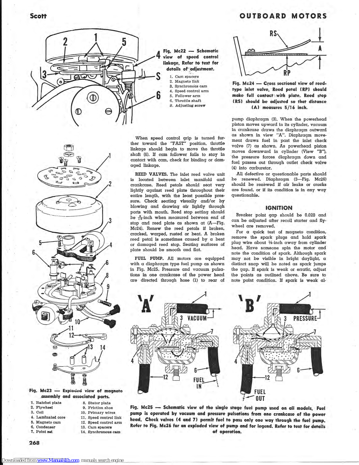
Scott
Loading...
#
4.5
2
5.5
342B
2
342B.pdf
342C
4
344
344C
2
345
2
348B
348
3
350
350B
350D
350R
350RL
355
355R
357B
2
370
370B
4
370R
375R
380R
380
382
382B
382C
2
384
385R
386
3
387
2
387B
388
4
388B
390R
399
410a
2
420A
430A
440A
2
460A
3
480A
4
490S
530T
570T
5 Hp Series
636S
3
637S
2
665DM
2
675DM
7.5 Hp Series
830Z
99a
99B
99C
99D
431
2
433
2
443
2
477
2
490
636
637
837
840
3600
4310
4312
2
805825
805826
805827
A
A2
A-236S
A-406
A407
A-416
3
A-417
2
A426
A436
4
A437
5
A457
3
Addict CX
ADDICT DISC
2
Addict Gravel
AIR-PAK 75i 2.2
AIR-PAK 75i 4.5
Alpha-1
Alpha Serie
ALPRIDE 1.0
ALPRIDE E1
ASSAULT
AV-3000
B
Berkley
Bicycle
2
Bicycle 2009
Bicycles
Big Ed
2
Big ed 2015
BIG ED 2016
B kids bike 2010
Loading...
Loading...
Nothing found
5 Hp Series
Service Data
8 pgs
1.66 Mb
0
Table of contents
Loading...
Scott 5 Hp Series, 16 Hp Series, 7.5 Hp Series, 10 Hp Series Service Data
...
Scott Service Data
Download
Specifications and Main Features
Frequently Asked Questions
User Manual
Download
Page 1
Page 2
Page 3
Page 4
Page 5
Page 6
Page 7
Page 8
Loading...
+
hidden pages
Unhide
You need points to download manuals.
1 point = 1 manual.
You can buy points or you can get point for every manual you upload.
Buy points
Upload your manuals
 Loading...