Service Manual AM/FM Stereo Receivers
H. H. SCOTT, INC., 20 Commerce Way, Woburn, Mass. 01888 Tel. (617) 933-8800
w Manualship.com manuals search en
The following safety precautions must be followed to assure continued reliability and safety against fire and shock hazard:
Printed in U.S.A. 11/82 029-1175-049
H.H. SCOTT ELECTRONICS®, Scottkit® and Scotsman~ are registered trademarks of H.H. SCOTT, Inc.
Service Manual AM/FM Stereo Receivers
H. H. SCOTT, INC., 20 Commerce Way, Woburn, Mass. 01888 Tel. (617) 933-8800
wnloaded from www.Manualslib.com manuals search engine
The following safety precautions must be followed to assure continued reliability and safety against fire and shock hazard:
a. The tester is connected to the power line receptacle and the power switch is turned on.
Printed in U.S.A. 11/82 029-1175-049
H.H. SCOTT ELECTRONICS®. Scottkit* and Scotsman* are registered trademarks of H.H. SCOTT. Inc.
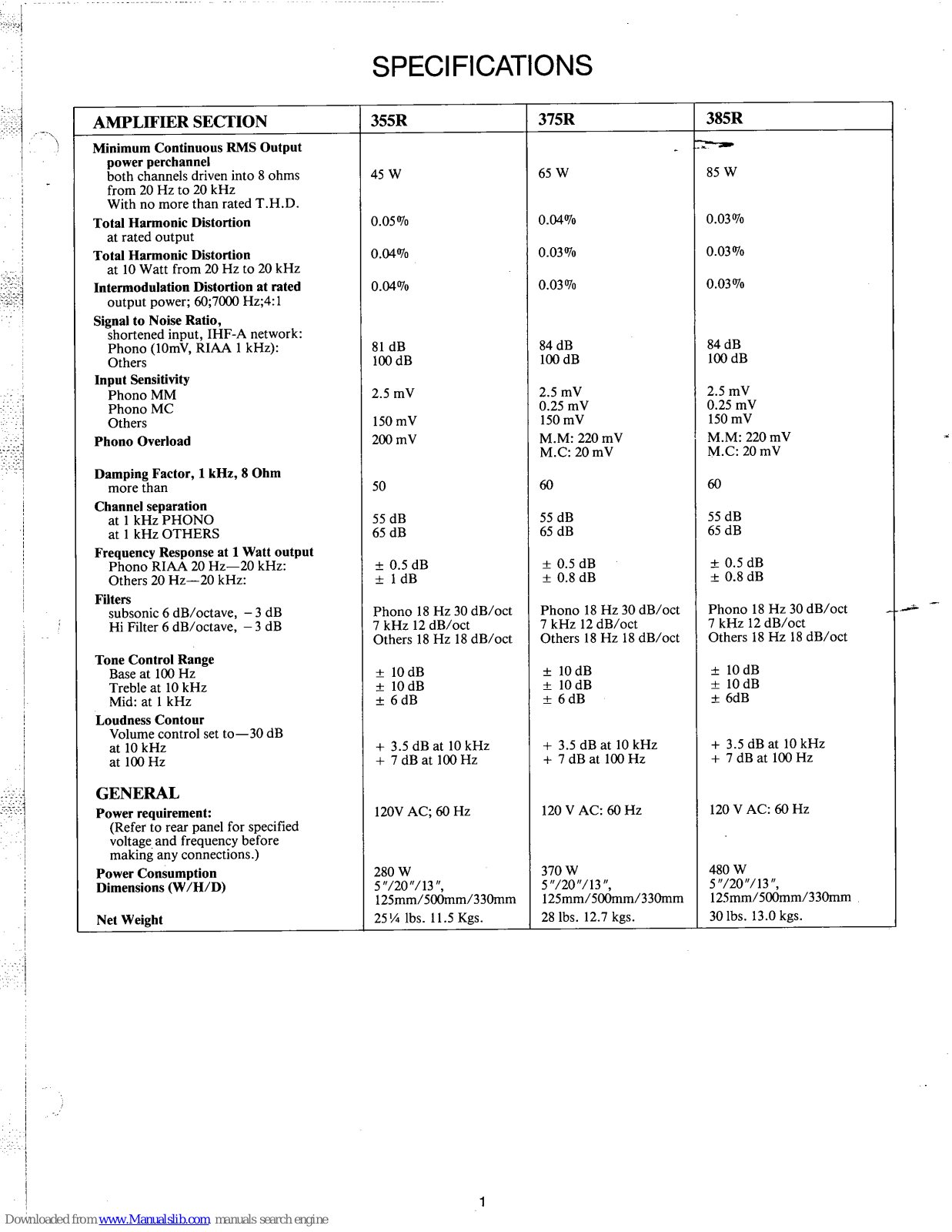
AMPLIFIER SECTION | 355R | 375R | 385R |
---|---|---|---|
Minimum Continuous RMS Output
power perchannel both channels driven into 8 ohms from 20 Hz to 20 kHz With no more than rated T.H.D. |
45 W | 65 W | 85 W |
Total Harmonic Distortion
at rated output |
0.05% | 0.04% | 0.03% |
Total Harmonic Distortion
at 10 Watt from 20 Hz to 20 kHz |
0.04% | 0.03% | 0.03% |
Intermodulation Distortion at rated
output power; 60;7000 Hz;4:1 |
0.04% | 0.03% | 0.03% |
Signal to Noise Ratio,
shortened input, IHF-A network: Phono (10mV, RIAA 1 kHz): Others Input Sensitivity Phono MM |
81 dB
100 dB 2.5 mV |
84 dB
100 dB 2.5 mV |
84 dB
100 dB 2.5 mV |
Phono MC | 2.5 111 V | 0.25 mV | 0.25 mV |
Others
Phono Overload |
150 mV
200 mV |
150 mV
M.M: 220 mV M.C: 20 mV |
150 mV
M.M: 220 mV M.C: 20 mV |
Damping Factor, 1 kHz, 8 Ohm
more than |
50 | 60 | 60 |
Channel separation
at 1 kHz PHONO at 1 kHz OTHERS |
55 dB
65 dB |
55 dB
65 dB |
55 dB
65 dB |
Frequency Response at 1 Watt output
Phono RIAA 20 Hz—20 kHz: Others 20 Hz—20 kHz: |
± 0.5 dB
± 1 dB |
± 0.5 dB
± 0.8 dB |
± 0.5 dB
± 0.8 dB |
Filters
subsonic 6 dB/octave, -3 dB Hi Filter 6 dB/octave, -3 dB |
Phono 18 Hz 30 dB/oct
7 kHz 12 dB/oct Others 18 Hz 18 dB/oct |
Phono 18 Hz 30 dB/oct
7 kHz 12 dB/oct Others 18 Hz 18 dB/oct |
Phono 18 Hz 30 dB/oct
7 kHz 12 dB/oct Others 18 Hz 18 dB/oct |
Tone Control Range
Base at 100 Hz Treble at 10 kHz Mid: at 1 kHz |
± 10 dB
± 10 dB ± 6 dB |
± 10 dB
± 10 dB ± 6 dB |
± 10 dB
± 10 dB ± 6dB |
Loudness Contour
Volume control set to—30 dB at 10 kHz at 100 Hz |
+ 3.5 dB at 10 kHz
+ 7 dB at 100 Hz |
+ 3.5 dB at 10 kHz
+ 7 dB at 100 Hz |
+ 3.5 dB at 10 kHz
+ 7 dB at 100 Hz |
GENERAL | |||
Power requirement:
(Refer to rear panel for specified voltage and frequency before making any connections.) |
120V AC; 60 Hz | 120 V AC: 60 Hz | 120 V AC: 60 Hz |
Power Consumption
Dimensions (W/H/D) |
280 W
5"/20"/13", 125mm/500mm/330mm |
370 W
5"/20"/13", 125mm/500mm/330mm |
480 W
5"/20"/13", 125mm/500mm/330mm |
Net Weight | 25¼ lbs. 11.5 Kgs. | 28 lbs. 12.7 kgs. | 30 lbs. 13.0 kgs. |
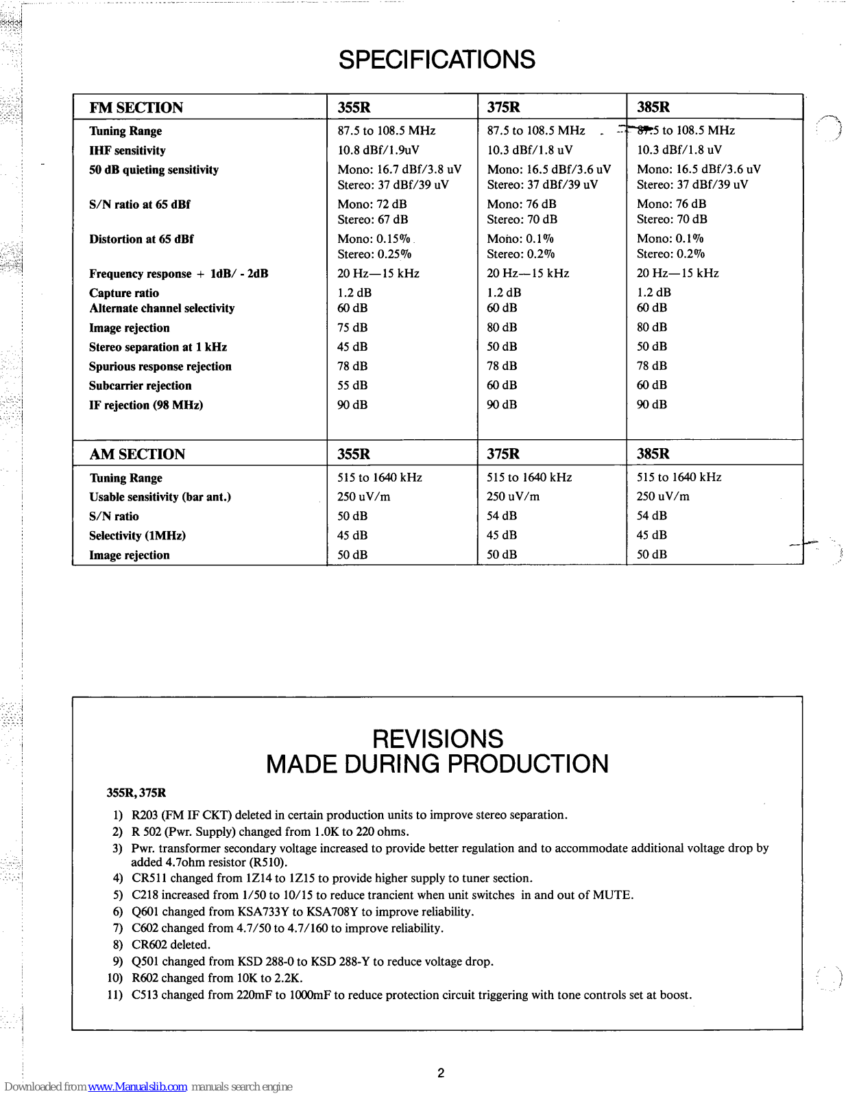
FM SECTION | 355R | 375R | 385R |
---|---|---|---|
Tuning Range | 87.5 to 108.5 MHz | 87.5 to 108.5 MHz | 87.5 to 108.5 MHz |
IHF sensitivity | 10.8 dBf/1.9uV | 10.3 dBf/1.8 uV | 10.3 dBf/1.8 uV |
50 dB quieting sensitivity |
Mono: 16.7 dBf/3.8 uV
Stereo: 37 dBf/39 uV |
Mono: 16.5 dBf/3.6 uV
Stereo: 37 dBf/39 uV |
Mono: 16.5 dBf/3.6 uV
Stereo: 37 dBf/39 uV |
S/N ratio at 65 dBf |
Mono: 72 dB
Stereo: 67 dB |
Mono: 76 dB
Stereo: 70 dB |
Mono: 76 dB
Stereo: 70 dB |
Distortion at 65 dBf |
Mono: 0.15%
Stereo: 0.25% |
Mono: 0.1%
Stereo: 0.2% |
Mono: 0.1%
Stereo: 0.2% |
Frequency response + 1dB/ - 2dB | 20 Hz—15 kHz | 20 Hz—15 kHz | 20 Hz—15 kHz |
Capture ratio
Alternate channel selectivity |
1.2 dB
60 dB |
1.2 dB
60 dB |
1.2 dB
60 dB |
Image rejection | 75 dB | 80 dB | 80 dB |
Stereo separation at 1 kHz | 45 dB | 50 dB | 50 dB |
Spurious response rejection | 78 dB | 78 dB | 78 dB |
Subcarrier rejection | 55 dB | 60 dB | 60 dB |
IF rejection (98 MHz) | 90 dB | 90 dB | 90 dB |
AM SECTION | 355R | 375R | 385R |
Tuning Range | 515 to 1640 kHz | 515 to 1640 kHz | 515 to 1640 kHz |
Usable sensitivity (bar ant.) | 250 uV/m | 250 uV/m | 250 uV/m |
S/N ratio | 50 dB | 54 dB | 54 dB |
Selectivity (1MHz) | 45 dB | 45 dB | 45 dB |
Image rejection | 50 dB | 50 dB | 50 dB |
The input section is designed using a balun coil that provides input matching for both 75 and 300 ohm transmission lines. The tuner section uses a MOSFET RF amplifier (Q1), transformer coupled to a bipolar mixer (Q2) for conversion. The local oscillator (Q3) is capacitively coupled to the base of Q2 where through the hetrodyne process a 10.7 MHz signal is produced for IF amplification.
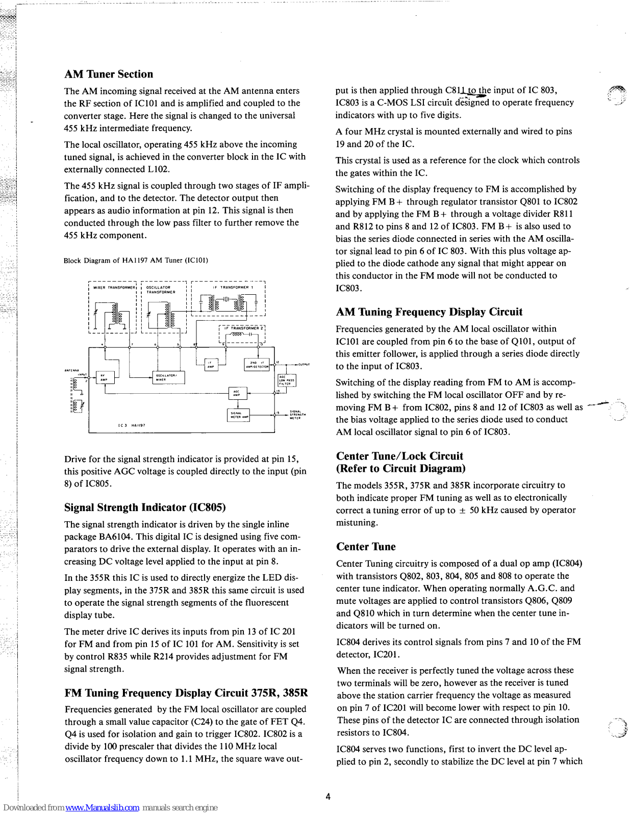
Output of the FM front end is transformer coupled to the IF amplifier circuit, composed of the 10.7 MHz transformer (T201), a transistor stage (Q201), 3 dual element ceramic filters (CF201, 202, and 203) and one integrated circuit (IC201). This integrated circuit contains the limiter amplifiers, quadrature detector, AGC amplifier, mute circuits, A.F.C. circuit and audio amplifier. Within the IC, limiter output is fed directly to one quadrature input. This signal is also connected to pin 8 where it is phase shifted by external coil L201 and reapplied to the other quadrature input at pin 9.
Two audio signals, opposite in phase, are obtained from the quadrature detector. Output of the first amplifier (pin 7) is at a DC level which varies with detuning and is used to provide the DC level shift necessary to operate the center tuning circuits. Output from the second amplifier (pin 6) is the composite audio signal which is coupled directly to the multiplex IC. The composite signal is internally muted in IC201 whenever a positive voltage is applied to pin 5. Drive for muting supplied from pin 12 provides a positive voltage when input to the IC is reduced to a low level.
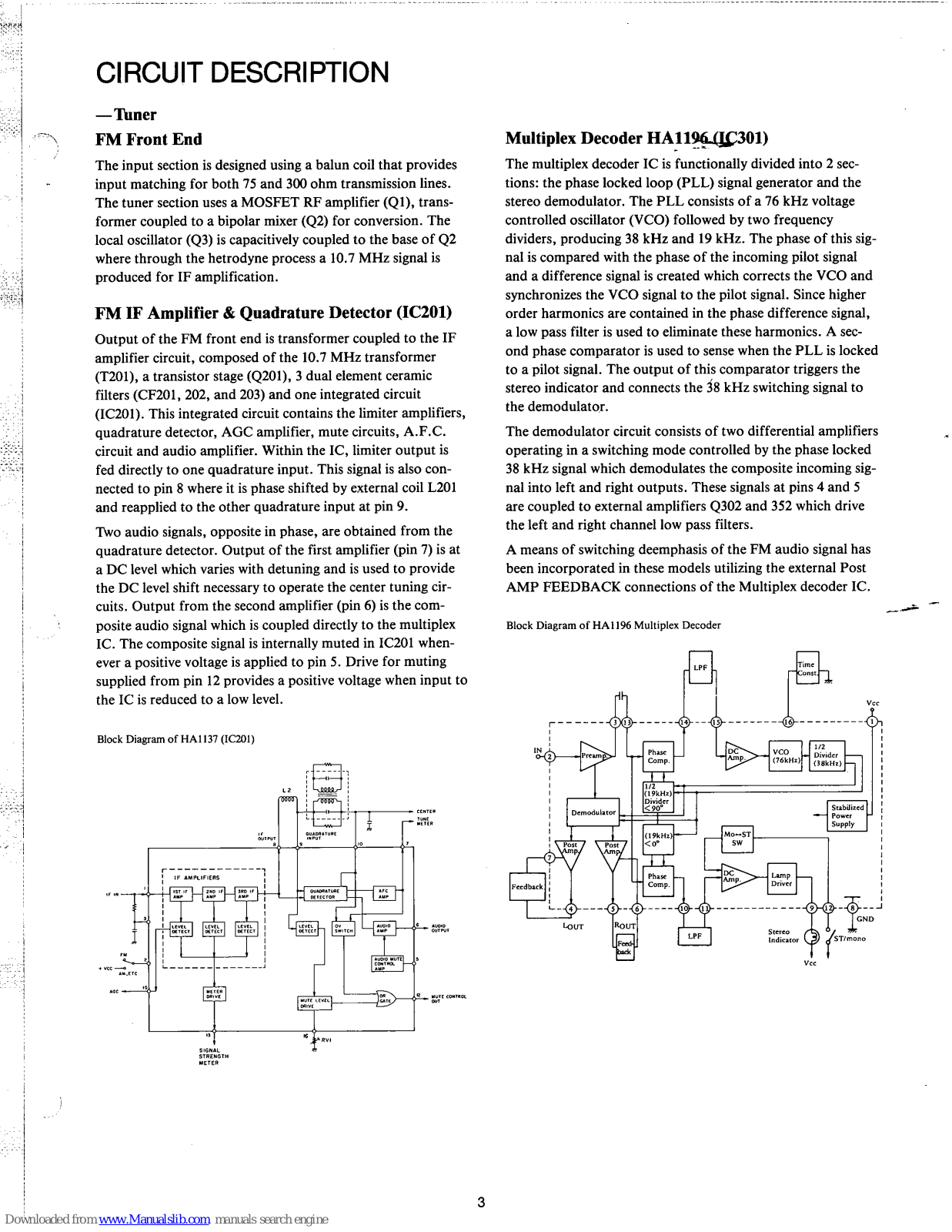
The multiplex decoder IC is functionally divided into 2 sections: the phase locked loop (PLL) signal generator and the stereo demodulator. The PLL consists of a 76 kHz voltage controlled oscillator (VCO) followed by two frequency dividers, producing 38 kHz and 19 kHz. The phase of this signal is compared with the phase of the incoming pilot signal and a difference signal is created which corrects the VCO and synchronizes the VCO signal to the pilot signal. Since higher order harmonics are contained in the phase difference signal, a low pass filter is used to eliminate these harmonics. A second phase comparator is used to sense when the PLL is locked to a pilot signal. The output of this comparator triggers the stereo indicator and connects the 38 kHz switching signal to the demodulator.
The demodulator circuit consists of two differential amplifiers operating in a switching mode controlled by the phase locked 38 kHz signal which demodulates the composite incoming signal into left and right outputs. These signals at pins 4 and 5 are coupled to external amplifiers Q302 and 352 which drive the left and right channel low pass filters.
A means of switching deemphasis of the FM audio signal has been incorporated in these models utilizing the external Post AMP FEEDBACK connections of the Multiplex decoder IC.
Block Diagram of HA1196 Multiplex Decoder
Block Diagram of HA1137 (IC201)
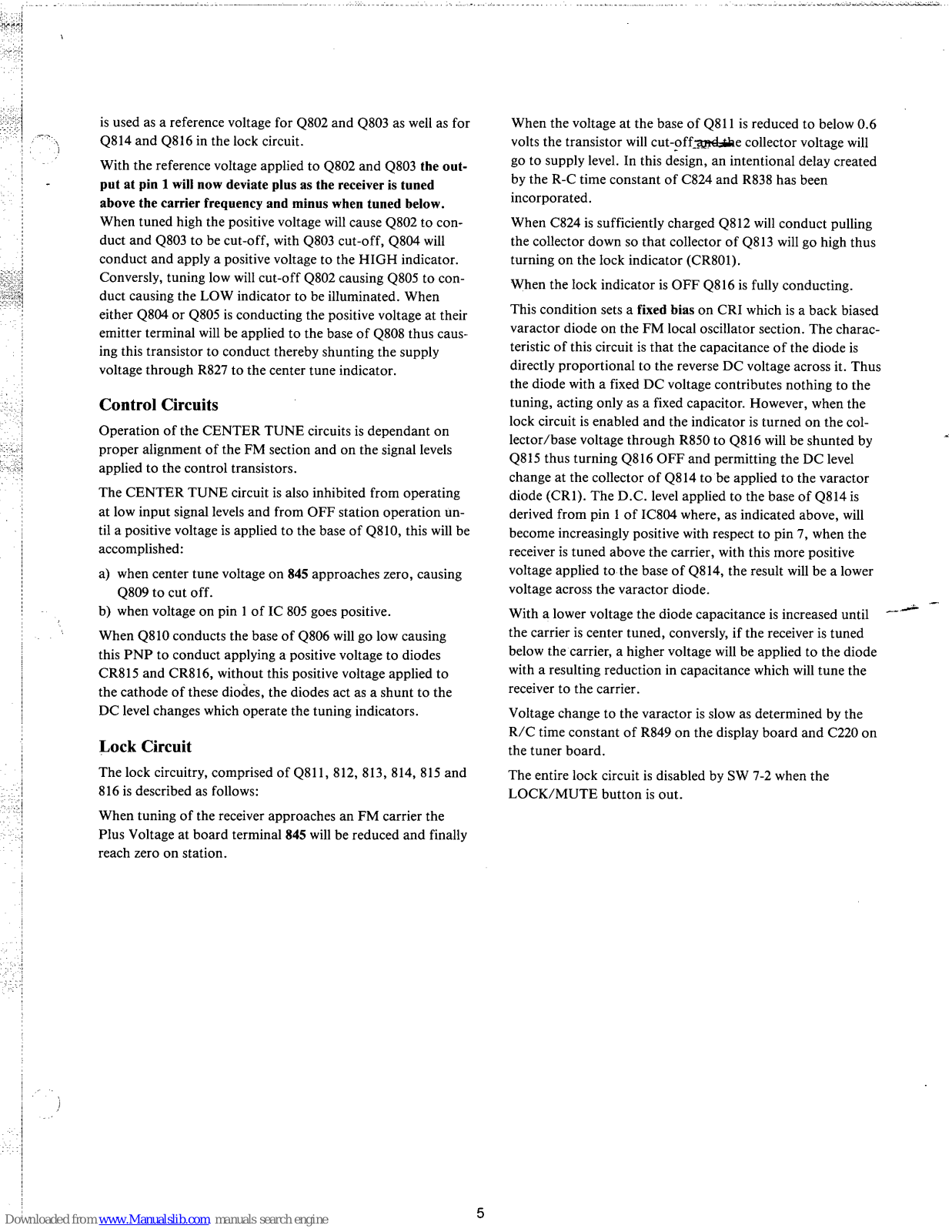
The AM incoming signal received at the AM antenna enters the RF section of IC101 and is amplified and coupled to the converter stage. Here the signal is changed to the universal 455 kHz intermediate frequency.
The local oscillator, operating 455 kHz above the incoming tuned signal, is achieved in the converter block in the IC with externally connected L102.
The 455 kHz signal is coupled through two stages of IF amplification, and to the detector. The detector output then appears as audio information at pin 12. This signal is then conducted through the low pass filter to further remove the 455 kHz component.
Block Diagram of HA1197 AM Tuner (IC101)
Drive for the signal strength indicator is provided at pin 15, this positive AGC voltage is coupled directly to the input (pin 8) of IC805.
The signal strength indicator is driven by the single inline package BA6104. This digital IC is designed using five comparators to drive the external display. It operates with an increasing DC voltage level applied to the input at pin 8.
In the 355R this IC is used to directly energize the LED display segments, in the 375R and 385R this same circuit is used to operate the signal strength segments of the fluorescent display tube.
The meter drive IC derives its inputs from pin 13 of IC 201 for FM and from pin 15 of IC 101 for AM. Sensitivity is set by control R835 while R214 provides adjustment for FM signal strength.
Frequencies generated by the FM local oscillator are coupled through a small value capacitor (C24) to the gate of FET Q4. Q4 is used for isolation and gain to trigger IC802. IC802 is a divide by 100 prescaler that divides the 110 MHz local oscillator frequency down to 1.1 MHz, the square wave out-
put is then applied through C811 to the input of IC 803, IC803 is a C-MOS LSI circuit designed to operate frequency indicators with up to five digits.
A four MHz crystal is mounted externally and wired to pins 19 and 20 of the IC.
This crystal is used as a reference for the clock which controls the gates within the IC.
Switching of the display frequency to FM is accomplished by applying FM B+ through regulator transistor Q801 to IC802 and by applying the FM B+ through a voltage divider R811 and R812 to pins 8 and 12 of IC803. FM B+ is also used to bias the series diode connected in series with the AM oscillator signal lead to pin 6 of IC 803. With this plus voltage applied to the diode cathode any signal that might appear on this conductor in the FM mode will not be conducted to IC803.
Frequencies generated by the AM local oscillator within IC101 are coupled from pin 6 to the base of Q101, output of this emitter follower, is applied through a series diode directly to the input of IC803.
Switching of the display reading from FM to AM is accomplished by switching the FM local oscillator OFF and by removing FM B+ from IC802, pins 8 and 12 of IC803 as well as the bias voltage applied to the series diode used to conduct AM local oscillator signal to pin 6 of IC803.
The models 355R, 375R and 385R incorporate circuitry to both indicate proper FM tuning as well as to electronically correct a tuning error of up to ± 50 kHz caused by operator mistuning.
Center Tuning circuitry is composed of a dual op amp (IC804) with transistors Q802, 803, 804, 805 and 808 to operate the center tune indicator. When operating normally A.G.C. and mute voltages are applied to control transistors Q806, Q809 and Q810 which in turn determine when the center tune indicators will be turned on.
IC804 derives its control signals from pins 7 and 10 of the FM detector, IC201.
When the receiver is perfectly tuned the voltage across these two terminals will be zero, however as the receiver is tuned above the station carrier frequency the voltage as measured on pin 7 of IC201 will become lower with respect to pin 10. These pins of the detector IC are connected through isolation resistors to IC804.
IC804 serves two functions, first to invert the DC level applied to pin 2, secondly to stabilize the DC level at pin 7 which
ownloaded from www.Manualslib.com manuals search engine
is used as a reference voltage for Q802 and Q803 as well as for Q814 and Q816 in the lock circuit.
With the reference voltage applied to Q802 and Q803 the output at pin 1 will now deviate plus as the receiver is tuned above the carrier frequency and minus when tuned below. When tuned high the positive voltage will cause Q802 to conduct and Q803 to be cut-off, with Q803 cut-off, Q804 will conduct and apply a positive voltage to the HIGH indicator. Conversly, tuning low will cut-off Q802 causing Q805 to conduct causing the LOW indicator to be illuminated. When either Q804 or Q805 is conducting the positive voltage at their emitter terminal will be applied to the base of Q808 thus causing this transistor to conduct thereby shunting the supply voltage through R827 to the center tune indicator.
Operation of the CENTER TUNE circuits is dependant on proper alignment of the FM section and on the signal levels applied to the control transistors.
The CENTER TUNE circuit is also inhibited from operating at low input signal levels and from OFF station operation until a positive voltage is applied to the base of Q810, this will be accomplished:
When Q810 conducts the base of Q806 will go low causing this PNP to conduct applying a positive voltage to diodes CR815 and CR816, without this positive voltage applied to the cathode of these diodes, the diodes act as a shunt to the DC level changes which operate the tuning indicators.
The lock circuitry, comprised of Q811, 812, 813, 814, 815 and 816 is described as follows:
When tuning of the receiver approaches an FM carrier the Plus Voltage at board terminal 845 will be reduced and finally reach zero on station.
When the voltage at the base of Q811 is reduced to below 0.6 volts the transistor will cut-off and the collector voltage will go to supply level. In this design, an intentional delay created by the R-C time constant of C824 and R838 has been incorporated.
When C824 is sufficiently charged Q812 will conduct pulling the collector down so that collector of Q813 will go high thus turning on the lock indicator (CR801).
When the lock indicator is OFF Q816 is fully conducting.
This condition sets a fixed bias on CRI which is a back biased varactor diode on the FM local oscillator section. The characteristic of this circuit is that the capacitance of the diode is directly proportional to the reverse DC voltage across it. Thus the diode with a fixed DC voltage contributes nothing to the tuning, acting only as a fixed capacitor. However, when the lock circuit is enabled and the indicator is turned on the collector/base voltage through R850 to O816 will be shunted by Q815 thus turning Q816 OFF and permitting the DC level change at the collector of Q814 to be applied to the varactor diode (CR1). The D.C. level applied to the base of O814 is derived from pin 1 of IC804 where, as indicated above, will become increasingly positive with respect to pin 7, when the receiver is tuned above the carrier, with this more positive voltage applied to the base of O814, the result will be a lower voltage across the varactor diode.
With a lower voltage the diode capacitance is increased until the carrier is center tuned, conversly, if the receiver is tuned below the carrier, a higher voltage will be applied to the diode with a resulting reduction in capacitance which will tune the receiver to the carrier.
Voltage change to the varactor is slow as determined by the R/C time constant of R849 on the display board and C220 on the tuner board.
The entire lock circuit is disabled by SW 7-2 when the LOCK/MUTE button is out.
These models use two separate operational amplifiers (IC901, 951) in a negative feedback configuration which provides the designer with means of gain adjustment and equalization.
Gain adjustment is fixed by resistors R914 and R915 while capacitors C910 and C911 provide the proper equalization to conform to the RIAA standard curve for recorded disc reproduction.
The circuit is powered by split supplies at a DC level suitable to provide the 200 mV overload capability at 1.0 kHz.
The tone control circuits (IC 401, 451) use of the high gain and low noise characteristics of the TA7322.
The tone control is a negative feedback type utilizing inverting Pin No. 3 for control.
As the frequency applied to the input of the IC decreases, the impedance of C411 increases thus reducing the signal applied to the treble control. Therefore at low frequencies the gain is mainly determined by the position of the bass control (R412L). Rotating the bass control toward C407 will boost the low frequencies by attenuating the feedback information below 1000Hz. Rotating the control toward C406 will attenuate low frequencies by reducing the circuit impedance thereby increasing feedback below 1000Hz.
As the frequency applied to the input increases the bass control will be shorted by C406 and C407 and the control will have no effect. However the impedance of C408 will decrease so that control R414L becomes the main feedback control. Rotating R414L toward R413 will increase feedback thus attenuating high frequencies. Rotating R414L toward R415 will reduce feedback and boost high frequencies.
At 1 kHz the bass and treble controls have little effect on the gain because of the impedance of capacitors C406, C407, C409 and C410. Thus at midrange frequencies R419L will control the gain of the tone control circuit.
The power amplifier design used in these models is a fully complementary design using a differential input amplifier composed of a matched transistor pair in a single package thus providing optimum common mode rejection and low DC offset.
With reference to one of the circuit diagrams, the first transistor (Q1401) provides the excellent common mode rejection and low DC offset.
Q1404 and Q1405 are used as voltage amplifiers to provide adequate signal level to driver transistors Q1406 and Q1407. Current gain is provided by the darlington connected driver/output circuit where Q1407 and Q1409 conduct for the negative swing and Q1406 and Q1408 conduct for the positive swing.
The output stage bias is set by the triple diode CR1401 and potentiometer R1412.
The amplifier is controlled by multiple feedback networks. DC feedback is provided through R1410 while R1411 and C1404 set the DC gain.
AC gain is determined by the ratio of R427 and R428.
The power supply in these models consists of a thermally protected power transformer with three separate secondary windings.
The first winding provides approximately 15.5-0-15.5 VAC which is rectified and regulated to provide the 12V DC supply for the tuner and part of the indicator circuits. Note: In later production the 15.5 VAC was increased to 18.0 VAC and zener changed to provide approx. 14V DC.
The second winding supplies approximately 82 VAC (385R) 72 VAC (375R) and 62 VAC (355R). This secondary voltage is rectified and filtered to provide a DC supply for the driver/output circuits, it is also regulated and further filtered for use in low level audio circuits.
The third winding, supplying approximately 5 VAC is used to provide filament current for the fluorescent displays.
This circuit is mounted on PCB #3014-523-010 and consists of six transistors, one relay and an assortment of coils, resistors, diodes and capacitors. Q607 and Q657 are located on the Main Amplifier PC Board and are actually connected to this board via terminals 1408 and 603.
Audio Power to the speakers and headphones is delayed until relay contacts K601 and K651 are closed.
When power is switched ON, AC will be applied from the high voltage secondary to terminal 601 where it is rectified by CR601, filtered and applied to the base of Q603, at this time supply voltages to all circuits has been established and the voltage on the base of PNPQ602 has been reduced thus causing this device to conduct and to energize the relay coil thus closing the relay contacts.
Since the SAFETY INDICATOR is connected between supply and the relay coil this LED will be switched off when voltage to the coil is raised to near supply voltage.
Circuitry used to sense offset and overload on the output circuit is composed of Q606, 607 and Q657.
Under normal operating conditions, these devices are not conducting therefore the collector of each remains at approximately the + supply voltage.
In operation, whenever any one of the above transistors sense an overload or offset condition in the output circuit either from internal or external causes one or more of the transistors will conduct which in turn applies a more negative voltage to base of Q601, when Q601 conducts the voltage on the base of Q604 increases and causes Q604 to conduct which in turn causes Q605 to conduct thus short circuiting the positive voltage applied to base of Q603. This voltage is short circuited through Q605 and R604 to ground. Thus Q603 is cutoff and Q602 will not conduct to energize the relay.
(Although typical of both channels, reference is made only to left channel components)
The output power indicator circuit is comprised of Q817, Q818, IC806 and the fluorescent display tube, FL801.
Since IC806 requires a linear input, conversion of the audio information from logarithmic to linear is performed
by the diode/resistor network CR805, 806, 807, 808 and resistors R854, 855.
Amplified output of Q817 is AC coupled to a germanium diode and to the base of Q818. Since IC806 also requires a DC input the output of Q818 is DC coupled through an adjustment potentiometer and applied to the input of IC806.
IC806 is a C MOS LSI circuit which performs the analog to digital conversion and peak holding function for both channels. IC806 is directly connected to the fluorescent display tube and as DC level on the input of IC806 increases the gates at the output progressively turn on, thereby applying the supply voltage to the appropriate input of the display tube.
The FL tube is driven by a MOS LSI (IC702) which performs the analogue to digital conversion and the peak holding for both channels. Since the input response of this IC is linear, a LOG signal conversion is required. This AC to DC conversion and LOG compression is performed by Diodes CR701, 751 and IC701.
Since this IC is a current activated device, its input voltage - sensitivity is determined by a series resistor to the inputs.
The auto-ranging circuit changes the sensitivity of the circuit by turning ON or OFF transistors Q-701 and Q-751.
The FLIP-FLOP (Q-702, Q-703) drives the input attenuator transistors and lights the corresponding decimal points on the display.
Need for change over, from low to high range is detected by diodes CR-711 and CR-710 which are connected to the last segments (most significant) of both channel displays, as long as the 2 least significant segments are lit, the range will remain in the high one. However if these segments turn off (underrange condition) for more than 3 seconds (determined by R-717 and C-709) the FLIP-FLOP will switch to the low range by O-705 triggering the transition.
These segments are monitored by diodes (CR-709 and C-708) which keep Q-705 in CUT OFF if these segments are lit.
Transistor Q-706 serves as system voltage regulator, utilizing the 8.2V internal reference of the LOG converter (IC701).
NOTE: Printed circuit board no. 3014-530-9606 is added in some production units to increase brightness of dots.
During production of these models certain production lots were fitted with a sensor attached to the power transformer designed to activate the protection circuitry if the power transformer temperature exceeded a predetermined level such as may occur under abnormal operating conditions.
If the receiver is made inoperable by the thermal sensor action the transformer must be allowed to cool before normal operation is resumed.
The subassembly voltage is supplied from a regulated source on the fluorescent display PCB as well as the positive voltage at term 603 of the protection board.
The regulated voltage applied to the first transistor, is used also to forward bias the triple diode and to provide a stable voltage on which to set the threshold for the second transistor.
With a known voltage drop across STV-3H at a given temperature the current through Q608 will be established thus setting the emitter voltage of the second transistor (Q609).
As the temperature applied to STV-3H increases the voltage drop across the diodes is reduced thus current through the first transistor is reduced and the emitter voltage drops. When the emitter voltage drops below the threshold set by the potentiometer, the second transistor will conduct thus activating the protection circuit to open the speaker relay contacts.
See page 10 for adjustment procedure.
The 385R is designed with a sensor on the output transistor heat sink. This circuit operates in the same manner as the transformer sensor, however the design differences require a higher reference voltage setting for Q609. See page 10 for adjustment procedure.
Audio signal generator. Level meter. Oscilloscope. Digital frequency counter, 0 - 100 kHz. FM multiplex signal generator. DMM, high impedance. 455 kHz sweep generator. 10.7 MHz sweep generator.
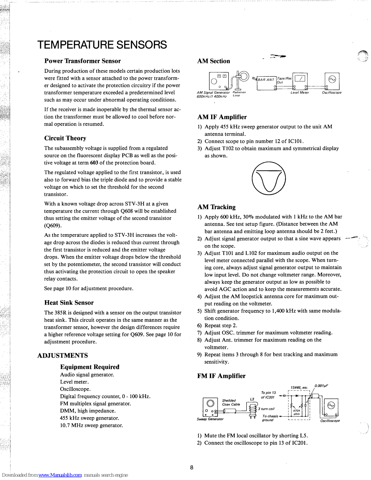
1) Mute the FM local oscillator by shorting L5.
2) Connect the oscilloscope to pin 13 of IC201.
Connect DC DMM between chassis and pin 15 of IC201. Tune receiver to signal generator with output set at 65 dBf, carefully tune for lowest AGC voltage. (Assuming proper IF alignment this step assures tuning to center of IF band pass.) Reconnect DMM to PCB Terminals marked TUNING METER and adjust T202 for zero volts.
With unit connected as above for tuning indicator adjustment, adjust T203 for minimum harmonic distortion.
Since there is some interaction between coil settings, repeat center tune and distortion adjustments for optimum results.
Equipment Required Audio signal generator. Digital multimeter. Speaker load resistors, 8 ohm 100 watt.
The following adjustments are the same for both the left and right channels.
Adjust R803 located on PCB behind front panel for 7.0-8.0V on pin 13 of IC801. Note this voltage should be as low as possible within the above range while still maintaining reliable display under normal user conditions.
Carefully tune receiver to center of AM station of known broadcast frequency. Adjust R809 until display reads the exact carrier frequency.
1) Follow the above procedure setting the voltage at the test terminals at 900 mV when heatsink temperature is 20 °C.
The models 355R and 375R utilize the same basic power display tube and both are driven by IC806, a type LC7555. The fundamental difference between the two tubes is the scale marking. Therefore, replacement parts should be ordered by part number for the appropriate model no.
The 385R utilizes a more sophisticated power meter, one which is the result of joint efforts by SCOTT and NIPPON ELECTRIC CO., LTD. Engineers to develop this multipurpose tube to SCOTT specifications.
The tuning display tube used in the 375R and 385R provides indication of AM and FM signal strength. FM center tuning, and a frequency read-out of both the AM and FM bands.
Drawings on the following pages show the pin connections to the various elements of the above mentioned FIPS.
THESE FIPS, BEING MADE OF GLASS ARE EASILY DAMAGED. A LOSS OF VACUUM OR BREAKAGE CAN RESULT FROM PHYSICAL SHOCK OR STRESS DURING HANDLING AND INSTALLATION.
The following pages contain outline drawings and lead codes for FIPs used in these models.
4 25 26 27 28 29 30 31 32 33
a 8a 9a 10 11 12 NP NC VP F |
50 - SCO - SC | ■ 1 2 ► |
FL 801
TYP. BG-32, BG-60 355R-375R |
||
---|---|---|---|---|---|
Pin no. 1 2 3 4 5 6 7 8 9 10 11 12 13 14 15 16 17 18 19 20 21 22 23 2 ectrode F NP SC 1a G 2a 3a 4a 5a 6a 1b 2b 3b 4b 5b 6b 7b G 3b 10 11 12 7 |
L 0.005 0.05 0.1 0.5 1.5 3 7 15
R 0.005 0.05 0.1 0.5 1.5 3 7 15 R 0.005 0.05 0.1 0.5 1.5 3 7 15 |
wnloaded from www Manualslib com manuals search engir
11
O
. ....................................
0
15.101 15201 15301 15.101 15201 15201 15.101 15201 15201
, .
4
20
SYMBOL | PART NO. | DESCRIPTION | SPECIFICATION | USED IN |
---|---|---|---|---|
1 | 6102-502-8101 | CABINET | 1.0T VINYL STEEL | ALL |
2 | 6103-500-3107 | SIDE-CABINET-L | 15T PLYWOOD VINYL | ALL |
3 | 6103-500-4102 | SIDE-CABINET-R | 15T PLYWOOD VINYL | ALL |
4 | 7334-500-1106 | WASHER-CABINET | P.P BLACK | ALL |
5 | 6804-502-2206 | SPACER-CABINET | 1.0 HIMERONE SHEET | ALL |
6 | 6022-505-6107 | CHASSIS-BOTTOM | 1.0T SPC-1 FZY | ALL |
7 | 6074-500-2101 | FOOT | RUBBER | ALL |
8 | 7702-507-7100 | PANEL-FRONT | AL EXTRU | 355R |
8 | 7702-507-7207 | PANEL-FRONT | AL EXTRU | 375R |
8 | 7702-507-7304 | PANEL-FRONT | AL EXTRU | 385R |
9 | 6463-500-7106 | GUIDE-KNOB "F" | ABS GREY | ALL |
10 | 7714-504-7207 | PLATE-BACK VOL. | 0.8T ALS | ALL |
11 | 7603-502-1109 | MASK-TUNING | ABS GREY | ALL |
12 | 7724-507-7104 | KNOB-TUNING | ALB ALUMITE | ALL |
13 | 7724-505-6103 | KNOB-ROTARY | ALB ALUMITE | ALL |
14 | 7724-506-0106 | KNOB-BALANCE | 94HB ACRYL CLR | ALL |
-15 | 7724-503-7108 | KNOB-VOLUME | ALB ALUMITE | ALL |
16 | 7653-501-4106 | DIAL WINDOW | 5.0T ACRYL CLR | ALL |
17 | 8012-504-1106 | SCALE-DIAL | 0.5T ALS OFFSET | 355R |
17 | 8012-504-1203 | SCALE-DIAL | 0.5T ALS OFFSET | 375R |
17 | 8012-504-1300 | SCALE-DIAL | 0.5T ALS OFFSET | 385R |
18 | 8014-502-7104 | BLIND-SCALE | ACRYL 0.5T × 373 × 13 | ALL |
19 | 8012-504-0208 | SCALE-BACK | 1.0T SPC-1 MET GRY | 355R |
19 | 8012-504-0101 | SCALE-BACK | 1.0T SPC-1 MET GRY | 375R |
19 | 8012-504-0305 | SCALE-BACK | 1.0T SPC-1 MET GRY | 385R |
20 | 6834-506-6103 | SPACER | RUBBER 3.5T | ALL |
21 | 8003-500-4101 | CAP-POINTER | ABS BLK | ALL |
22 | 7654-503-3104 | FILTER-WINDOW | ACRYL 0.5T | 355R |
22 | 7653-503-0102 | FILTER-WINDOW | ACRYL 0.5T | 375R |
22 | 7653-503-0209 | FILTER-WINDOW | ACRYL 0.5T | 385R |
23 | 0859-141-6008 | TEFLON TAPE | W 25.4×33Y×0.8T | ALL |
24 | 6613-506-1105 | BRKT-GUIDE PNTR | 0.8T SPCY-1 FZW | ALL |
25 | 5104-509-1100 | SHAFT-TUNING | MB R2 GC10 | ALL |
26 | 6603-500-6107 | HOLDER-LED,S | ABS NATURAL | ALL |
27 | 6614-583-2106 | BRACKET, SCALE, R | 1.0T SPC-1 FZW | ALL |
SYMBOL | PART NO. | DESCRIPTION | SPECIFICATION | USED IN | i. |
---|---|---|---|---|---|
28 | 5214-501-3104 | PULLY GUIDE | PA WHITE | ALL | |
29 | 7394-500-5106 | SHAFT GUIDE | FE FZY | ALL | 1.111 |
30 | 6613-504-3109 | BRACKET, SCALE L | 1.0T SPC-1 FZW | ALL | |
31 | 6603-101-2104 | HOLDER-DIGITRON | PS H/T 100% | 355R, 375R | |
31 | 6603-101-3105 | HOLDER-FL | ABS BLACK | 385R | |
32 | 6614-587-4108 | BRKT-PWB (F) | 1.2T S PC-1 FZW | ALL | |
33 | 6022-505-5104 | CHASSIS-FRONT | 1.0T SPC-1 FZY | 355R | |
33 | 6022-505-5102 | CHASSIS-FRONT | 1.0T SPC-1 FZY | 375R | |
33 | 6022-505-5209 | CHASSIS-FRONT | 1.0T SPC-1 FZY | 385R | |
34 | 7604-502-1109 | MASK-KNOB | 0.5T HIMERONE | ALL | |
35 | 7723-500-5106 | KNOB-PUSH "F" | ABS | ALL | |
36 | 6463-500-1106 | GUIDE-KNOB | PE SOFT NAT | ALL | |
37 | 6654-507-9105 | SUPPORT-G POINTER | STS P1 1.0 | ALL | |
38 | 6023-502-1100 | FRAME-R | 1.2T SPC-1 FZY | ALL | |
39 | 5223-500-6104 | WHEEL-DRUM | ABS NATURAL | ALL | |
40 | 6674-510-2100 | SPRING, DIAL | STS P1 1.0 | ALL | |
41 | 6674-508-6103 | STOP-SPRING | SPS-27 0.3T | ALL | |
42 | 4543-500-8102 | SHIELD FENCE | 0.3T TE SBC | ALL ~ | |
43 | 4544-503-1103 | SHIELD PLATE-T | 0.3T TE SBC | ALL | |
44 | 4544-503-0108 | SHIELD PLATE-P | 0.3T TE-SBC | ALL | |
45 | 5684-501-1101 | HEAT SINK, TR | 1.5T ALS | ALL | |
46 | 6613-506-0100 | BRACKET, TRANS | 1.2T SPC-1 FZY | ALL | |
47 | 5682-502-2105 | HEAT SINK | 2.5T ALS | ALL | |
48 | 6654-507-8100 | SUPPORT-B PNTR | STS P1 1.0 | ALL | |
49 | 6844-503-1201 | WASHER-CABINET | 0.8T FIBER | ALL | |
50 | 6634-105-6409 | CLAMPER-WIRE | 0.5T SPC-1 FZY | ALL | |
51 | 6634-100-1904 | CLAMPER-WIRE | SPC-1 0.6 TFT | ALL | |
52 | 5683-501-3104 | HEAT SINK A | 2.0T ALS | 355R | |
52 | 5682-501-1207 | HEAT SINK SUB | 1.5T ALS | 375R, 385R | |
53 | 6023-502-0100 | FRAME-L | 1.2T SPC-1 FZY | 355R | |
53 | 6023-502-0105 | FRAME-L | 1.2T SPC-1 FZY | 375R, 385R | |
54 | 6022-505-4107 | CHASSIS, REAR | 1.0T SPC-1 BLK | 355R | |
54 | 6022-505-4204 | CHASSIS, REAR | 1.0T SPC 1 BLK | 375R | |
54 | 6022-505-4505 | CHASSIS, REAR | 1.0T SPC 1 BLK | 385R | |
55 | 3339-543-0105 | JACK, AUX | ABS & 4P BLK | ALL | ( 1 ) |
56 | 3339-543-0202 | JACK, AUX | ABS & 2P BLK | ALL |
SYMBOL | PART NO. | DESCRIPTION | SPECIFICATION | USED IN |
---|---|---|---|---|
57 | 6834-502-0101 | SPACER | 1.0T×30×25 RUBBER | ALL |
58 | 3104-501-6109 | TERMINAL, SCREW | ABS | ALL |
59 | 7304-100-2100 | WASHER-PLAIN | 0.5T×3.5×7P1 FE FZY | ALL |
60 | 3303-500-1100 | TERMINAL BD | 5T SCREW ABS BLK | ALL |
61 | 6634-100-8103 | CLAMPER, CORD | HEYCO SR4N4 | ALL |
62 | 6634-100-7108 | CLAMPER, CORD | HEYCO SR 3P4 | ALL |
63 | 3304-501-6105 | TERM BD PUSH | DRP 0.03 4P | ALL |
64 | 6634-101-8106 | BAND, CORD WIRE | P.P BLACK | ALL |
65 | 4543-500-9107 | SHIELD-FENCE FL | 0.3T TE-S BC | 375R, 385R |
65 | 6603-103-7105 | HOLDER-LED | ABS NAT | 355R |
66 | 4543-501-0105 | CAP-SHIELD, FL | 0.3T TE-SBC | 375R, 385R |
66 | 6834-503-5109 | MASK, LIGHT T | RUBBER, SPONGE 6T | 355R |
67 | 6634-100-6103 | BAND WIRE | P.P BLK | 355R |
67 | 6613-506-4207 | BRKT-PROT PWB | 0.8T SPC-1 FZY | 375R, 385R |
68 | 4544-502-2105 | SHIELD CAP-2 | TE-SBC 0.3T | 355R |
68 | 5684-502-8109 | HEATSINK, DIODE | ALS 1.5T | 375R, 385R |
69 | 3124-100-7105 | TAP-STUD | 0.5T SPC-1 BT 2 | 355R |
69 | 6614-591-6101 | BRKT-BAND CAP | 1.2T SPC-1 FZY |
375R, 38
|
70 | 3114-102-4208 | LUG | 0.3T TE-S BC | 355R |
70 | 6634-102-7201 | BAND-CAP | 0.8T SPC-1 FZY | 375R, 385R |
71 | 4544-500-5104 | SHIELD FENCE | TE-SBC 0.3T | 355R |
71 | 3934-103-1103 | INSUL-TR | NYLON 66 | 375R, 385R |
72 | 6804-502-8106 | SPACER-CAB | 0.5T HIMERONE | 375R, 385R |
73 | 4544-500-5104 | SHIELD-FENCE | TE-SBC 0.3T | 375R, 385R |
74 | 3114-102-4208 | LUG | 0.3T T TE-SBC | 375R, 385R |
75 | 3934-500-7100 | INSULATOR PLATE | 1.0T FIBRE | 375R, 385R |
76 | 3124-100-7105 | TAP-STUD | 0.5T SPC-1 BT2 | 375R, 385R |
77 | 4544-502-2105 | SHIELD CAP-2 | TE-SBC 0.3T | 375R, 385R |
78 | 6634-100-6103 | BAND WIRE | P.P BLK | 375R, 385R |
79 | 7654-565-3106 | INDICATOR-SEL | ACRYL CLEAR | 385R |
80 | 6604-513-2104 | HOLDER-LED | RUBBER, 94V-OW | 385R |
81 | 7018-130-0815 | SCREW-FH | + M3×8FE FZY | ALL |
82 | 7028-140-1010 | SCREW-TH | + M4×10 FE FZY | ALL |
83 | 7048-126-0437 | SCREW-RH | + M2.6×4 FE FZY | ALL |
84 | 7048-130-0616 | SCREW-RH | + M3×6 FE FZY | ALL |
SYMBOL | PART NO. | DESCRIPTION | SPECIFICATION | USED IN |
---|---|---|---|---|
85 | 7048-130-1213 | SCREW-RH | + M3 × 12 FE FZY | 375R, 385R |
85 | 7048-130-1019 | SCREW-RH | + M3 × 10 | 355R |
86 | 7048-130-0412 | SCREW-RH | + M3×4 FE FZY | ALL |
87 | 7048-130-1514 | SCREW-RH | + M3 × 15 FE FZY | ALL |
88 | 7048-130-1019 | SCREW-RH | + M3 × 10 FE FZY | 375R, 385R |
89 | 7148-130-0619 | SCREW-TAP, RH | 1-3×6 FE FZY | ALL |
90 | 7148-530-0615 | SCREW-TAP RH | 2S-3×6 FE FZY | ALL |
91 | 7148-530-0819 | SCREW-TAP RH | 2S-3×8 FE FZY | ALL |
92 | 7148-530-0837 | SCREW-TAP RH | 2S-3×8 FZB | ALL |
93 | 7148-130-0831 | SCREW-TAP RH | 1-3×8 FZB | ALL |
94 | 7148-130-1012 | SCREW-TAP RH | 1-3×10 FZB | ALL |
95 | 7148-530-1212 | SCREW-TAP RH | 2S-3×12 FZY | 355R |
95 | 7148-530-1018 | SCREW-TAP RH | 2S-3×10 FZY | 375R, 385R |
96 | 7148-530-1212 | SCREW-TAP RH | 2S-3×12 FZY | 375R, 385R |
97 | 7158-530-0832 | SCREW-TAP BH | 2S-3×8FE FZB | ALL |
98 | 7098-130-0611 | SCREW-FLANGE, RH | + M3×6 FE FZY | ALL |
99 | 7154-100-6303 | SCREW-TAP RH | 2S-3×8 FE FZY | ALL |
100 | 7154-100-6701 | SCREW-TAP RH | 2S-3×2 FE FZY | ALL - |
101 | 7128-540-0810 | SCREW-TAP TH | 2S-4×8 FE FZY | ALL |
102 | 7128-540-1213 | SCREW-TAP TH | 2S-4×12 FE FZY | ALL |
103 | 7128-540-2032 | SCREW-TAP TH | 2S-4×20 FZB | ALL |
104 | 7304-100-2100 | WASHER-PLAIN | 0.5T×3.5×7.5P1 | ALL |
105 | 7304-500-2106 | WASHER-PLAIN | 4.5 P1×100 P1×1.5T | ALL |
106 | 7318-103-0014 | WASHER-SPRING | PI3.0 (3.1×5.9×0.7T) | ALL |
107 | 7328-204-0011 | WASHER-TOOTHED | BPI (4.3×8.5×T0.45 | ALL |
108 | 7208-113-0017 | NUT-HEX | 1M3 FE FZY | ALL |
109 | 7208-114-0010 | NUT-HEX | 1M4 FE FXY | ALL |
121 | 2309-120-0102 | LED-SQUARE | LN 217 RPL | ALL |
122 | 2309-119-0108 | LED-SQUARE | LN 317 GP | ALL |
123 | 3509-501-0203 | SWITCH-SPK/PWR | SFR 2045/SDRIR | 355R, 375R* |
123 | 3509-501-0504 | SWITCH-SPK/PWR | SFR 20451/SDR3R | 355R, 375R* |
123 | 3509-201-1502 | SWITCH-SPK | SRF 485 | 355R, 385R** |
123 | 3509-501-0708 | SWITCH-SPK | SRF 4078 | 385R |
124 | 1219-108-0105 | VR-BASS | GMPE 20FM7C100K | 355R |
124 | 1269-111-1503 | VR-BASS | GMPE 20FM7C100K | 375R, 385R |
125 | 1269-111-1309 | VR-MID/TREB | GM70E 20FM7C100K | 355R |
*Early production, grey power switch. **Later production using micro switch, see items 162, 163, 164.
SYMBOL | PART NO. | DESCRIPTION | SPECIFICATION | USED IN |
---|---|---|---|---|
125 | 1269-111-1406 | VR-MID/TREB | GM70E 20F C100K | 375R, 385R |
126 | 1299-102-0107 | VR-VOL | FJ60E 2SFM11 | 355R |
126 | 1299-102-0204 | VR-VOL | FJ60E W250K/B100K | 375R, 385R |
127 | 3509-201-0507 | SW-ROT-SLIDE | SRZ VO45N | 355N |
127 | 3509-501-0106 | SW-ROT-SLIDE | SRZW045N | 375R, 385R |
128 | 3529-203-1702 | SW-PUSH, FIL/LOUD | SUF32 4C-4C, 2C | ALL |
129 | 3529-203-1809 | SW-PUSH, MODE-TAPE | SUF52 2C×29 | ALL |
130 | 3339-511-0203 | JACK-EARPHONE | HLJ0290-01-020 | ALL |
132 | SEE TRANSISTOR LIS | Г | ALL | |
133 | SEE TRANSISTOR LIST | Г | ALL | |
134 | 2189-105-1007 | VARISISTOR-STV3H | 7MA 1.6-1.8V | ALL |
135 | 1809-400-0101 | VARICON-AIR | С774Ј | ALL |
136 | SEE CAPACITOR LIST | ALL | ||
137-146 | PCB ASSYS ARE GENE | ERALLY NOT AVAILABLE FOR REPI | LACEMENT* | |
147 | 2319-101-0302 | DIGITRON-PWR | BG 32 | 355R |
147 | 2319-101-0409 | DIGITRON-PWR | BG 60 | 375R |
147 | 2319-101-0506 | DIGITRON-PWR | FIP 12AW 12YS | 385R |
148 | 2309-117-0102 | LED METER | LNO5202P | 355R |
148 | 2319-101-0205 | DIGITRON-FREQ | 7-LT-08 | 375R, 385R |
149 | 2869-197-9003 | TRANS-PWR | W/O SENSOR | 355R |
149 | 2869-197-7031 | TRANS-PWR | W/SENSOR | 355R |
149 | 2869-197-9100 | TRANS-PWR | 375R | |
149 | 2869-198-0108 | TRANS-PWR | 385R | |
150 | 3334-500-1005 | JACK-AC OUTLET | 125V 15A S-16444 | ALL |
151 | 3053-806-3101 | POWERCORD, AC | STP1 18 BLK | ALL |
152 | 3304-501-6105 | TERM BD, PUSH | DRP 003 4P | ALL |
153 | SEE PARTS LIST UND | ER COILS | ALL | |
154 | 3519-501-0509 | SWITCH-INPUT SEL | SSR 22602D | 375R, 385R |
155 | 3349-519-9100 | SW, DENTENT, FLEX | SWR 6300 | 375R, 385R |
156 | DEEMPHASIS PWB | NOT AVAILABLE | ALL | |
157 | 3519-201-0609 | SW, SLIDE, DEEMP | SSB 023N | ALL |
158 | 3934-501-110 | INSULATOR, FIB-A | 0.8T × 45 × 52 | 385R |
159 | 3934-501-2108 | INSULATOR, FIB | 1.0T × 160 × 72 | 385R |
160 | 6614-595-4103 | BRKT-BWB, S | 1.2T SPC-1 FZY | 385R |
161 | 5682-501-5107 | HEATSINK, B | 2.0T ALB BLK | 385R |
SYMBOL | PART NO. | DESCRIPTION | SPECIFICATION | USED IN |
---|---|---|---|---|
162 | 6614-592-9109 | BRKT PWR, SW | 1.0T SPC-1 FZY | 385R |
163 | 5244-500-3106 | CAM-S/W | 2.0T SPC-1 FZY | 385R |
164 | 3599-902-020 | SW/PWR | SDR3R | 355R, 375R* |
164 | 3579-101-0105 | MICRO SW | АН 715457 | 355R, 375R, 385R |
165 | 3014-528-9109 | PWB, THERM PROT | CHECK AVAILABILITY | 385R |
166 | 3013-507-8102 | PWB, DRIVE, FL | CHECK AVAILABILITY | 385R |
167 | 3014-529-0107 | PWB, LED FUNCTION | CHECK AVAILABILITY | 385R |
168 | 2309-101-4103 | LED | LD 30A RED 3 P1 | 385R |
୍ତ୍ରି
*Used in early production. (Grey pwr sw only).
SYMBOL | PART NO. | DESCRIPTION | SPECIFICATION | USED IN |
---|---|---|---|---|
CR801 | 2309-119-0108 | LED-SQUARE | LN 317 GP | ALL |
CR301, CR603 | 2309-120-0102 | LED-SQUARE | LN 217 RP | ALL |
CR512, CR825 | ||||
CR716, CR717 | 2309-101-4103 | LED | LD30 A RED 3PI | ALL |
CR718 | ||||
2309-104-2102 | LED-DELTA | SLP 239B | 355R Pointer | |
SEE SCHEMATIC | ||||
ALL MODELS | 2169-301-2901 | DIODE, SWITCHING | 1SS53 | See Schematic |
CR-1 | 2169-501-1603 | DIODE, AFC | KS3302, 4-7.5PF | ALL |
CR507, CR508 | 2169-404-2200 | DIODE-ZN WZ220 | 50MW 20.8-22.3V | ALL 🛆 |
CR501, CR502 | 2169-201-0504 | DIODE, RECTIFIER | IN4001, 1A, 50V | ALL 🛆 |
CR503, CR504 | 2169-201-1509 | DIODE, RECTIFIER | IN4142, 3A 400V | 355R 🛆 |
CR505, CR506 | ||||
CR509, CR510, CR601 | 2169-201-0601 | DIODE, RECTIFIER | IN4002, 1A 100V | ALL 🛆 |
CR511 | 2169-403-9202 | DIODE-ZN, BZ150 | IW 13.8-15.6V | ALL 🛆 |
CR902 | 2169-404-1409 | DIODE-ZN, WZ-061 | 50MW 5.6-6.5V | 375R, 385R 🛆 |
CR901 | 2169-404-6103 | DIODE-ZN Wz120 | 500MW, 11,4-12.6V | 375R, 385R 🛆 |
CR608, CR1401 | 2189-105-1007 | VARISTOR-STV 3H | 7MA 1.6-1.8V | ALL 🛆 |
CR1451 | ||||
CR1402, CR1403 | 2169-201-0708 | DIODE, RECTIFIER | IN4003, 1A,200V | ALL 🛆 |
CR1452, CR1453 | ||||
CR1404, CR605 | 2169-403-2207 | DIODE, ZN, WZ-182 | 50MW, 16.8-19.1V | ALL 🛆 |
CR810, CR811 | 2169-101-1403 | DIODE, GER, IN60 | IR 15UA | 355R, 375R |
CR860, CR861 |
SYMBOL | PART NO. | DESCRIPTION | SPECIFICATION | USED IN |
---|---|---|---|---|
4709-031-4004 | FUSE | NOR 125V 6A, 31, 8 UL | 375R, 385R 🛆 | |
F505 | 4709-031-3106 | FUSE | NOR 125V 5A, UL | 355R 🛆 |
F801 | 4709-133-1402 | FUSE W/LEAD | SLO 125/250 0.5A UL | all 🛆 |
F501, F502 | ||||
F503, F504 | 4709-131-3309 | FUSE W/LEAD | NOR 125V, 8A UL | ALL 🛆 |
SYMBOL | PART NO. | DESCRIPTION | SPECIFICATION | USED IN |
---|---|---|---|---|
IC701 | 2119-101-4500 | IC | TA 7318P | 385R |
IC806 | 2119-201-1300 | IC-DISPLAY | LC 7555 | 355R, 375R |
IC702 | 2119-201-3203 | IC-DISPLAY | LC 7556 | 385R |
IC101 | 2119-201-0907 | IC-AM IF | HA 1197 | ALL |
IC201 | 2119-201-0402 | IC-FM IF | HA 1137W | ALL |
IC301 | 2119-201-1106 | IC-MPX | HA 1196 | ALL |
IC901, IC951 | 2119-401-0206 | IC-OP | TA 7322P | ALL |
IC401, IC451 | ||||
IC801 | 2119-601-0301 | IC-REG | LA 5700 | 375R, 385R 🛆 |
IC802 | 2119-601-0204 | IC-PRESCALER | SP 8629 | 375R, 385R |
IC803 | 2119-201-1203 | IC-FREQ. DISP. | LC 7258 | 375R, 385R |
IC804 | 2119-401-0303 | IC-OP | NJM 4558 DD | ALL |
IC805 | 2119-201-2004 | IC-SIG | BA 6104 | ALL |
SYMBOL | PART NO. | DESCRIPTION | SPECIFICATION | USED IN |
---|---|---|---|---|
R214, R312 | 1249-102-0908 | VR-SEMI | SR19R B220K | ALL |
R226 | 1249-102-0403 | VR-SEMI | SR19R B22K | ALL |
R303, R808, R809 | 1249-102-0306 | VR-SEMI | SR19R B10K | ALL |
R861, R877 | ||||
R1412, R1462 | 1249-102-0102 | VR-SEMI | SR19R B470 | ALL |
R627, R803 | 1249-102-1000 | VR-SEMI | SR19R B2.2K | ALL |
R835, R705 | 1249-102-0209 | VR-SEMI | SR19R B4,7K | ALL |
R755 | ||||
R886 | 1249-102-0704 | VR-SEMI | SR19R B100K | 375R |
R504, R505 | 1049-301-3106 | R-METAL OXIDE | RSIP 3.3K-K | ALL 🛆 |
R709 | ||||
R506, R507 | 1049-301-2402 | R-METAL OXIDE | RSIP 820-K | ALL 🛆 |
R509 | 1049-105-2202 | R-METAL OXIDE | RS3P 560K | ALL 🛆 |
R1407, R1457 | 1049-301-0101 | R-METAL OXIDE | RSIP 10K | |
R1408, R1458 | ||||
R1422, R1472 | ||||
R1413, R1463 | 1049-301-1300 | R-METAL OXIDE | RSIP 100-K | ALL 🛆 |
R1424, R1474 | ||||
R1417, R1467 | ||||
R1418, R1468 | 1049-301-1504 | R-METAL OXIDE | RSIP 150-K | all 🛆 |
SYMBOL | PART NO. | DESCRIPTION | SPECIFICATION | USED IN |
---|---|---|---|---|
R1421, R1471 | 1049-315-0104 | R-METAL OXIDE | RS2P 10J | ALL |
R1422, R1472 | 1049-315-0104 | R-METAL OXIDE | RS2P 10J | 385R Only |
R1423, R1473 | 1049-103-2002 | R-METAL OXIDE | RS2P 390-K | 375R, 385R |
R612 | 1049-105-1906 | R-METAL OXIDE | RS3P 330-K | 385R |
R613 | 1049-103-2400 | R-METAL OXIDE | RS2P 820-K | 385R |
R612 | 1049-103-1803 | R-METAL OXIDE | RS2P 270-K | 375R, 355R |
R1423, R1473 | 1049-103-1900 | R-METAL OXIDE | RS2P 330-K | 355R |
R613 | 1049-301-2402 | R-METAL OXIDE | RS1P 820-K | 355R, 375R |
R1422, R1472 | 1049-301-0101 | R-METAL OXIDE | RS1P 10K | 355R, 375R |
R1419, R1469 | 1035-905-0908 | R-CEMENT WIRE | RW5P 0.47K | ALL |
R1420, R1470 |
SYMBOL | PART NO. | DESCRIPTION | SPECIFICATION | USED IN |
---|---|---|---|---|
Q2, Q3 | 2139-301-0508 | TRANSISTOR | KSC 1674-0 | ALL |
Q101, Q201 | 2139-301-8508 | TRANSISTOR | KSA 838-0 | ALL |
Q202, 603, 604 | 2139-302-7409 | TRANSISTOR | KSA 945-Y | ALL |
606, 607, 657 | ||||
802, 803, 808 | ||||
809, 810, 811 | ||||
812, 813, 814 | ||||
815, 816, 817 | ||||
818, 819, 820 | ||||
Q701, 751 | 2139-302-7409 | TRANSISTOR | KSA 945-Y | 385R |
Q501 | 2149-401-2609 | TRANSISTOR | KSD 288-Y* | ALL |
Q801 | 2149-401-2609 | TRANSISTOR | KSD 288-0 | 375R, 385R |
Q1401, 1451 | 2139-901-0104 | TRANSISTOR | KSA 798G | ALL |
Q1402, 1452 | 2149-102-6304 | TRANSISTOR | KSA 965 Y | ALL |
1403, 1453 | ||||
1407, 1457 | 2149-102-6304 | TRANSISTOR | KSA 965 Y | 355R |
Q1404, 1454 | 2149-304-6405 | TRANSISTOR | KSC 2235 Y | ALL |
1405, 1455 | ||||
Q1406, 1456 | 2149-304-6405 | TRANSISTOR | KSC 2235 Y | 355R |
Q1406, 1456 | 2149-403-3309 | TRANSISTOR | KSD 669 A-B | 375R, 385R |
Q1407, 1457 | 2149-201-7606 | TRANSISTOR | 2SB 649 A-B | 375R, 385R |
Q1408, 1458 | 2149-101-6107 | TRANSISTOR | KSA 1187 Y | 375R |
Q1408, 1458 | 2149-301-3207 | TRANSISTOR | KSC 2579 Y | 355R |
Q1408, 1458 | 2149-301-7605 | TRANSISTOR | KSC 2921 Y | 385R |
Q1409, 1459 | 2149-201-0300 | TRANSISTOR | 2SA 1187 | 375R |
Q1409, 1459 | 2149-101-3209 | TRANSISTOR | KSA 1104 Y | 355R |
Q1409, 1459 | 2149-101-3607 | TRANSISTOR | KSA 1215 Y | 385R |
Q901, 951 | 2139-103-8603 | TRANSISTOR | KTA 970 BL | 375R, 385R |
Q902, 952 | 2139-305-6704 | TRANSISTOR | KTC 2240 BL | 375R, 385R |
Q601, 602 | 2139-103-7103 | TRANSISTOR | KSA 708 Y | ALL |
Q605, 804 | 2139-103-3802 | TRANSISTOR | KSA 733 Y | ALL |
805, 806 | ||||
Q702, 703 | 2139-103-3802 | TRANSISTOR | KSA 733 Y | 385R |
704 | ||||
Q608, 609 | 2149-301-3409 | TRANSISTOR | KSC 1008 Y | 385R |
Q1 | 2139-601-4806 | FET | 3SK 73 GR | ALL |
Q4 | 2139-601-0301 | FET | 2SK 212 | 375R, 385R |
*Changed from D2880 to D288Y during production, D288Y is specified.
SYMBOL/
EXP. VIEW NO. |
PART NO. | DESCRIPTION | SPECIFICATI ON | USED IN |
---|---|---|---|---|
67 | 7224-100-9102 | NUT-HEX, CAP | FE ENI | ALL |
68 | 7044-100-1106 | SCREW-RH | FE-FNI | ALL |
69 | 6614-117-3100 | BRACKET-ANT BAR | 1.0T SPC-1 FZB | ALL |
L101/70 | 2509-305-1016 | COIL-ANT MW W/CORE | CORE 10 PIX 120 | ALL |
99 | 6634-106-4101 | BAND-BAR ANT | 94HB ABS BLACK | ALL |
SYMBOL | PART NO. | DESCRIPTION | SPECIFICATION | USED IN |
---|---|---|---|---|
L2, L3 | 2509-106-2104 | COIL, FM ANT | TR-A7JZ004S | ALL |
L1 | 2519-106-3104 | COIL, FM ANT | TR-A7JZ002S | ALL |
L4, L202, L103 | 2429-040-0302 | COIL, CHOKE | 2.2UH-K Q30 | ALL |
L5 | 2539-107-3107 | COIL-FM OSC | TR-A7JZ003S | 355R, 375R |
L5 | 2539-108-4105 | COIL-FM OSC | CFOR 12 P1010 | 385R |
L201 | 2429-020-0708 | COIL-CHOKE | 18 UH-K Q30 F2R5 | ALL |
L102 | 2619-511-7093 | COIL-RF, AM | 340UH A-BASE | ALL ~- |
L1401, 1451 | 2429-060-0401 | COIL, CHOKE SPKR | 2R5UH-KQ50 | ALL |
T101*** | 2619-010-4027 | COIL, OSC MW | 150UH A BASE | ALL |
T103 | 2749-118-0204 | TRANS-IF, AM | 7MM CAN | ALL |
T102 | 4529-313-0106 | FILTER-CER, AM | 7MM CAN | ALL |
T201 | 2739-501-0203 | COIL-FM, MIX | TRIO MMA002S | ALL |
T202 | 2739-503-0102 | TRANS-FM, IF | TRIO MM 013M | ALL |
T203 | 2739-501-0300 | TRANS-FM, IF | TRIO MM 014M | ALL |
LF301, 351 | 4529-415-0509 | FILTER, LP | 208 BLR 315 7R | ALL |
L101* | 2509-205-1309 | COIL-ANT, AM W/CORE | CORE 10 PIX 120 | 355R, 375R |
L101** | 2509-305-1016 | COIL-ANT, MW W/CORE | CORE 10 PIX 120 | ALL |
¥801 | 4539-501-0403 | CRYSTAL | HC-18/U, 4.0 MHz | 375R, 385R |
L6 | 2509-105-5106 | BALUN | TV750301A2 | ALL |
K601 | .4724-100-1201 | RELAY, PROTECT | MS4U DC24V 30MA | ALL |
3519-201-0609 | SWITCH, SLIDE | SSBO23N (Deemphasis) | ALL | |
CF 201, 202, 203 | 4529-309-0103 | FILTER, CERAMIC | SFE 10.7 MA8 | ALL |
*Used in early production, and shown on exploded view. **Used in later production, see insert. ***Replacement part may be marked 2539-403-0204.
SYMBOL | PART NO. | DESCRIPTION | SPECIFICATION | USED IN |
---|---|---|---|---|
C515 | 1469-502-0706 | CAP-CERAMIC AC | 125 VAC 0.0047 | ALL 🛆 |
C120 | 1509-452-1001 | CAP-POLYSTYRENE | CQ09S 50V 330-J | ALL |
C302 | 1509-452-1108 | CAP-POLYSTYRENE | CQ09S 50V 510-J | |
C311, C361 | ||||
C511, C512 | 1619-018-2701 | CAP-ELECTROLYTIC | 50V 8200M PCB | 355R 🛆 |
C511, C512 | 1619-018-3201 | CAP-ELECTROLYTIC | 63V 10000M PCB | 375R, 385R∆ |
C416, C417, C418 | 1609-802-9908 | CAP-ELECTROLYTIC NP | CEO4W 100V 0.047M | ALL 🛆 |
C466, C467, C468 | ||||
C315, C365 | 1509-452-1700 | CAP POLYSTYRENE | CQ09S 50V 1100-J | ALL |
C314, C364 | 1509-452-1302 | CAP POLYSTYRENE | CQ09S 50V 560-J | |
C1 | 1809-400-0101 | VARICON | C774J | ALL |
C27 | 1829-511-0104 | C TRIMMER | ECV-12 W06×32E | ALL |
SYMBOL/
EXP. VIEW NO. |
PART NO. | DESCRIPTION | SPECIFICATION | USED IN |
---|---|---|---|---|
FL801 | 2319-101-0302 | FLUORESCENT TUBE | B6-32 | 355R |
FL801/147 | 2319-101-0409 | FLUORESCENT TUBE | B6-60 | 375R |
FL701/147 | 2319-101-0506 | FLUORESCENT TUBE | FIP12AW12YS | 385R, |
IC806 | 2119-201-1300 | INTEGRATED CIRCUIT | LC7555 | 355R, 375R |
IC702 | 2119-201-2303 | INTEGRATED CIRCUIT | LC7556 | 385R |
IC701 | 2119-101-4500 | INTEGRATED CIRCUIT | TA7318P | 385R |
Q701, Q751 | 2139-302-7409 | TRANSISTOR | KSC945Y | 385R |
Q702, Q703, Q704 | 2139-103-3802 | TRANSISTOR | KSA733Y | 385R |
CR701-714, CR751 | 2169-301-2901 | DIODE | 1SS53 | 385R, |
CR821 | 2169-301-2901 | DIODE | 1SS53 | 355R, 375R |
R886 | 1249-102-0704 | VR-SEMI | SR19R B100K | 375R |
C831 | 1509-121-2702 | CAP-POLYESTER | M50V 0.12M-J | 375R |
CR820 | 2309-117-0102 | LED METER | LN 05202P | 355R |
CR827, CR828, CR829 | 2169-301-2901 | DIODE | 1SS53 | 355R, 375R |
PROBLEM | POSSIBLE CAUSE | · CORRECTION |
---|---|---|
FM distortion. | Low B + supply to FM IF. |
Verify that Q501 is KSD 288 Y
(See parts list). |
Severe frequency jumping, or drift. | Defective FM OSC trimmer. | Replace trimmer cap C-27. |
Oscillation at all levels, all inputs. |
12V Reg. transistor Q501 oscillates at
VHF band. |
Increase value of C-509 from 0.001 to 0.047 ceramic disc. |
Display does not light up. | Check for broken wire or PCB track to FIP or IC. | Repair as indicated. |
-NOTE- | - | |
To verify that FIP is or is not defective a new FIP n
in question with sufficient terminals connected to e display elements. |
nay be connected directly across the part
nergize the filament B + and one or more |
|
Protection circuit remains
activated. (Protection LED ON). |
|
1) Adjust per test procedure |
Protection circuit remains
activated. (Protection LED ON). |
2) A number of production units have been
found with a 10 ohm resistor replacing R1417, R1418, R1467 or R1468 causing severe offset. |
2) Replace this critical part with factory specified replacement-Adj. bias. |
Occasional fuzzy sound at low level output. | Oxidized relay contacts. |
Verify by shorting across contacts on
PCB, clean contacts with strip of clean white paper pulled through contacts under pressure or replace relay. |
Display frequency stays at 87.5
or very slow AM to FM. |
Incorrect setting of regulated supply—IC 801. | Adjust R803 for 7.5-8.0V at Pin 13 of IC801. |
Poor FM sensitivity, does not switch to stereo. | Defective ceramic filter. | Replace filter with same color code. |
Thump in speakers when switch-
ing through input functions. Noisy tone/volume controls. |
Excessive DC offset in IC or leaky coupling/
feedback capacitors. |
Troubleshoot and replace parts as indicated. |
355R FM tuning indicator
(green pointer LEDS) not operating. |
FM detector alignment or defect. Defective component in circuit Q802-Q810 or IC804. | Troubleshoot and replace parts as indicated. |
Excessive high frequencies in phono mode. | Incorrect equalization or improper cartridge loading. | Check response to R1AA spec. Provide additional cartridge loading 100-300 pF. |
Output section oscillates under certain speaker load conditions. | Reactive loads causing circuit instability. | Increase value of C 1417 and C1467 from 2 pF to 5pF. |
H. H. SCOTT INC. 20 Commerce Way Woburn, MASS. 01801
tel.: 617-933-8800