

Page 1
www.scot t-sport s.com
BIKE OWNER’S MANUAL 2015
All right s reserved © 2014 SC OTT Sports SA
SCOTT Spo rts SA | 17 Route du Cro chet | 1762 Givisiez | Sw itzerland
Distrib ution: SSG (Europ e) Distrib ution Center SA
P.E.D Zon e C1, Rue Du Kiel l 60 | 6790 Aubang e | Belgium
V4.3/19012015
SCOTT
PLASMA 5
Page 2
02
PLASMA 5 | BIKE OWNE R’S MA NUAL 2015 BIKE OWN ER’S M ANUAL 20 15 | PLASMA 5
03
www.scot t-sport s.com
ENGLISH
ENGLISH
The Plasma C arbon bikes should be a djusted exac tly to the
current ride r for reaching maximum s afety and performa nce
while riding.
Please note that all adjustments should be done at your local
SCOTT dealer or fo llowing to this manual.
CONTENT
Plasma Concept . . . . . . . . . . . . . . . . . . . . . . . . . . . . . . . . . . . . . . . . . . . 04
Geom et ry/ Technical Data Plasma 5 . . . . . . . . . . . . . . . . . . . . . . . . . . . . . . . 05
Plasma 5 Frameset Content . . . . . . . . . . . . . . . . . . . . . . . . . . . . . . . . . . . . 06
Specific Torques Values Table . . . . . . . . . . . . . . . . . . . . . . . . . . . . . . . . . . . 06
Rear Drop out and Replaceable Derailleur Hanger. . . . . . . . . . . . . . . . . . . . . . 06
Cable Routing: for Electronic Shifting . . . . . . . . . . . . . . . . . . . . . . . . . . . . . . 08
Cable Routing: for Mechanical Shifting . . . . . . . . . . . . . . . . . . . . . . . . . . . . . .10
Fork . . . . . . . . . . . . . . . . . . . . . . . . . . . . . . . . . . . . . . . . . . . . . . . . . . . . 12
Headset/Stem Body TT5. . . . . . . . . . . . . . . . . . . . . . . . . . . . . . . . . . . . . . .12
Seatpost . . . . . . . . . . . . . . . . . . . . . . . . . . . . . . . . . . . . . . . . . . . . . . . . .14
Stem/Handlebar . . . . . . . . . . . . . . . . . . . . . . . . . . . . . . . . . . . . . . . . . . . .16
Brake . . . . . . . . . . . . . . . . . . . . . . . . . . . . . . . . . . . . . . . . . . . . . . . . . . .18
Brake Covers . . . . . . . . . . . . . . . . . . . . . . . . . . . . . . . . . . . . . . . . . . . . . . 21
Storage Box . . . . . . . . . . . . . . . . . . . . . . . . . . . . . . . . . . . . . . . . . . . . . . 22
Hydration System . . . . . . . . . . . . . . . . . . . . . . . . . . . . . . . . . . . . . . . . . . 23
Warranty. . . . . . . . . . . . . . . . . . . . . . . . . . . . . . . . . . . . . . . . . . . . . . . . 24
Page 3
04
PLASMA 5 | BIKE OWNE R’S MA NUAL 2015 BIKE OWN ER’S M ANUAL 20 15 | PLASMA 5
05
ENGLISH
ENGLISH
PLASMA CONCEPT
Plasma is the re sult of 2 years of research and development b ased on the fe edback
of the SCOTT-triathlon an d time trial athletes searching for one of the m ost effi cient
aerodynamics orientated frames in the market.
SCOTT’s focus was not only on the frame and rider aerod ynamics b ut also on the
bike’s ergonomics and adjustability as well as th e frame front end stiffness .
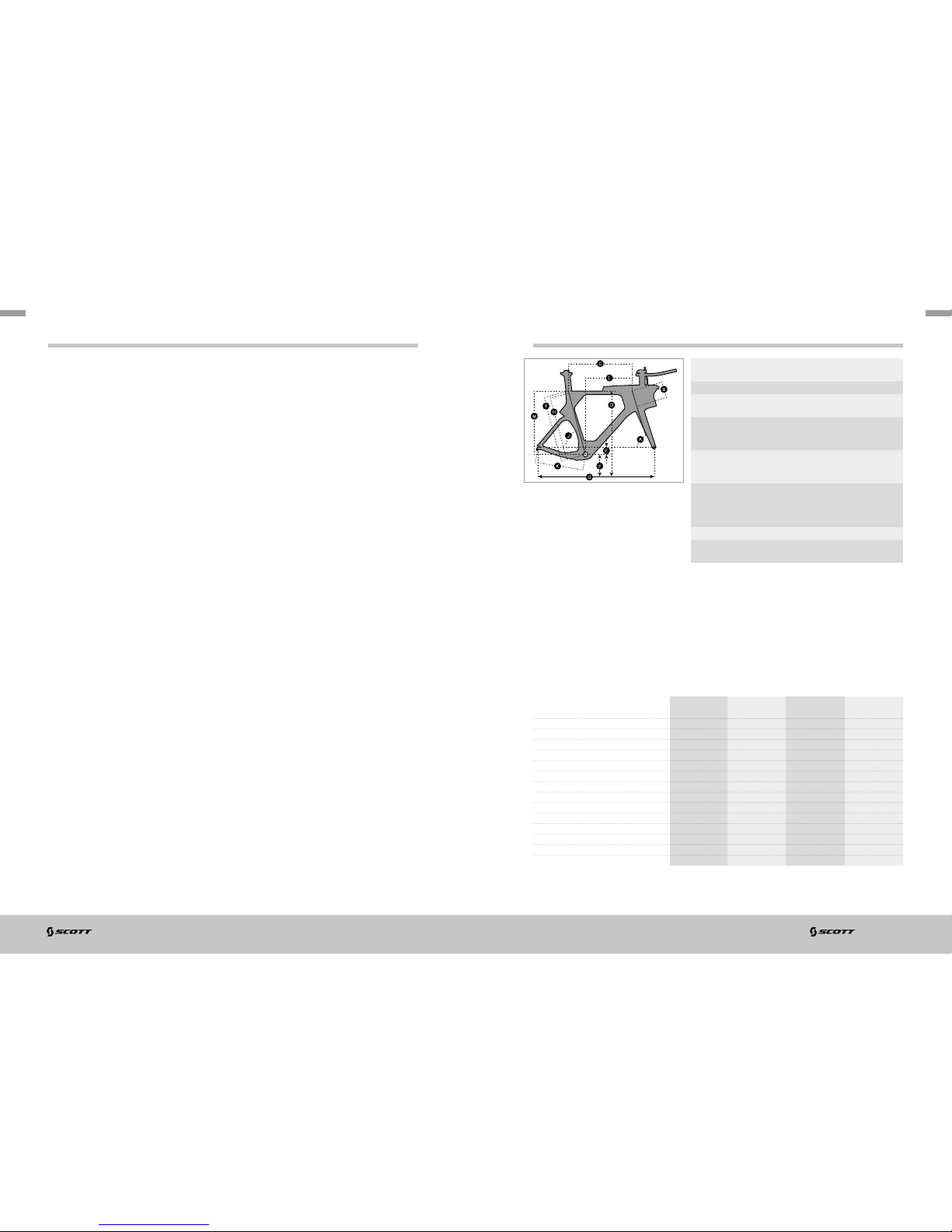
GEOMETRY/TECHNICAL DATA PLASMA 5
Headtube diameter Plasma 5: 1 ” /1.1/8”, taper ed, cups
semi-in tegrated
BB housing PF BB 86
Rear brake SHIMANO direct mount
compatible brake calipers
Front brake Compatib le with both SHIMAN O
direct mo unt and single bolt f ront
brake calipers.
Front brake c over Only com patibl e with TEKTRO
SCTT 161411501 brake des igned
for PLASMA5
Seat post s addle
rails clamps
Differe nt seatpost saddl e rail
clamps ar e available to m atch with
your saddle: 7x7mm, 8x8.5mm or
7x9.6mm
Rear hanger Compatib le plasma 4 and plas ma 5
Shifting Mechanical and electrical shifting
compatible
S/51 M/54 L/57 XL/60
A
HEAD TUBE ANGLE 72.0 ° 73.0 ° 7 3.0 ° 73 .5 °
B
HEAD TUB E LENGTH 110.0 mm 4 .3 in 13 8.0 mm 5.4 in 170.0 mm 6.7 in 199.0 m m 7. 8 in
C
TOP TUBE HORIZONTAL 524.0 mm 20.6 in 544.0 mm 21.4 in 564.0 mm 22.2 in 5 83.0 mm 23.0 in
D
STANDOVER HEIGHT 779.0 mm 30.7 in 809.0 mm 3 1.9 in 839.0 m m 33.0 in 8 69.0 mm 3 4.2 in
E
BB OFFSET -65.0 m m -2.6 in -6 5.0 mm -2 .6 in - 65.0 mm -2 .6 in - 65.0 mm -2.6 in
F
BB HEIGHT 269.0 mm 1 0.6 in 269.0 mm 10.6 in 269.0 mm 10.6 in 269.0 mm 10.6 i n
G
WHEEL BASE 965.0 mm 38.0 in 983.0 mm 38.7 i n 1,009.0 mm 39.7 in 1,029 .0 mm 40.5 in
H
BB CENTER TO TOP TUBE CENTER 514.8 mm 20.3 in 544.6 m m 2 1.4 in 5 74.4 m m 2 2.6 in 604.2 mm 23.8 in
I
BB CENTER TO TOP O F SEATTUBE 529.8 mm 20.9 i n 559. 6 mm 22 .0 in 589 .4 mm 23 .2 in 61 9.2 mm 24. 4 in
J
SEATTUBE ANGLE 74.0 ° 75.0 ° 75.0 ° 76.0 °
K
CHAINSTAY MIN. 403.0 mm 15 .9 in 403.0 mm 15 .9 in 4 03.0 mm 15.9 in 4 03.0 mm 15.9 i n
L
REACH 380.0 mm 15 .0 in 397.0 mm 15.6 in 414.0 mm 1 6.3 in 430.0 mm 1 6.9 in
M
STAC K 510.0 mm 20.1 i n 540.0 mm 21 .3 in 570.0 mm 22.4 i n 600.0 mm 23.6 in
N
STEM LENGTH 85.0 mm 3. 3 in 85. 0 mm 3.3 i n 85.0 mm 3.3 in 85.0 mm 3.3 in
Page 4
06
PLASMA 5 | BIKE OWNE R’S MA NUAL 2015 BIKE OWN ER’S M ANUAL 20 15 | PLASMA 5
07
ENGLISH
ENGLISH
PLASMA 5 FRAMESET CONTENT
1. Frame
2. Fork
3. Headset
4. Seatpost
5. Stem/H andlebar
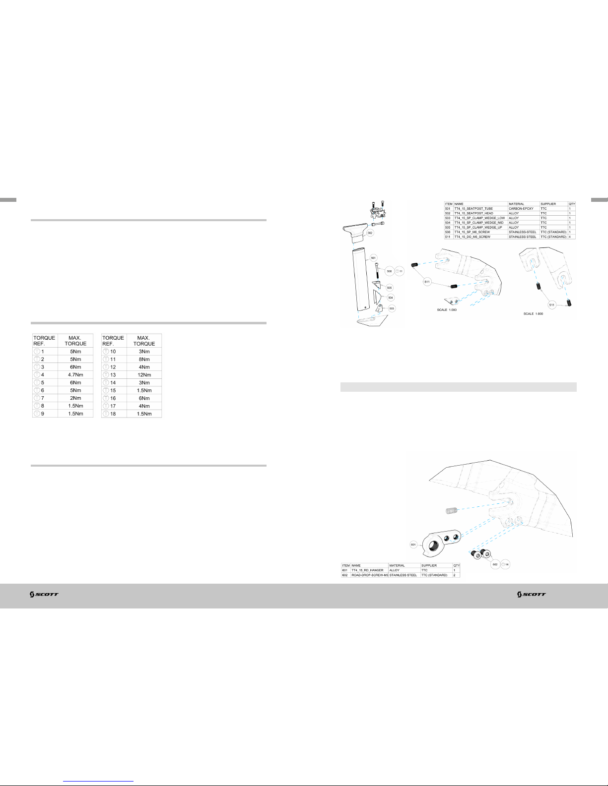
Rear derailleur hanger:
place the rear derailleur hanger i n the cavity an d tighten the 2x M6 screws to their
specified torques.
IMPORTANT
Rear derailleur hanger (601 + 2 *602): 239178 is compatible wit h Plasm a 4 and
Plasma 5
Drop out a djustment screws: Stand ard M5*10mm headless sc rew availab le in any
hardware shop.
6. Front Brake
7. Brake Covers
8. Storage Box
9. Hydration System
REAR DROP OUT AND REPLACEABLE DERAILLEUR
HANGER
Setup screw:
Dropout le ngth can be set to adjust the re ar wheel tire clearance with the frame
(100) thanks to the rear dropout screws (5 11). The chainstays length can be set from
403mm to 413m m.
- Loos en the screw to set a longer chainstays length,
- Tighten the screw to set a shorter chai nstays length .
Make sure right a nd left side are set at the same length by assembling the rear wheel
and verifying it is centred with the chainstays.
SPECIFIC TORQUES VALUES TABLE
Page 5

08
PLASMA 5 | BIKE OWNE R’S MA NUAL 2015 BIKE OWN ER’S M ANUAL 20 15 | PLASMA 5
09
ENGLISH
ENGLISH
CABLE ROUTING: FOR ELECTRONIC SHIFTING
Front Derailleur (FD) & Rear Derailleur (RD) wires:
Route the COMMAND ele ctric wire (approx. 1 000m m) down from the headtube long
hole to the bottom bracket right h and housing.
Route the FD wire (approx. 2 00mm) down from the frame front derailleur exit hole
to the bottom bracket right hand housing.
Route the RD wire (approx . 500mm) down from the frame right dropout exit hole to
the bottom bra cket right han d housing.
Route the BATTERY wire (approx. 6 00mm) down the seattube to the b ottom
bracket right hand housing.
Plug all wires to the junction b ox SM-JC41 , insert the box into the fra me through
the bottom bra cket right han d housing a nd make sure all wires will not dis turb the
bottom bracket assembly.
Rear Brake (RB) Cable Housing:
IMPORTANT
To avoid any damage to t he frame struct ure put a housing e nd plug at the end of
the housing.
Place the hou sing into the headtube lon g hole, push the housing until it touches
the rear end of the headtub e (you may feel a resistance), orient the housing
up and push th e housing again, it will then follow the h eadtube down and
continue its travel along the downtube, continue running the cable housing into
the frame.
Once the hou sing is visible from the bot tom bracket opening, le ad the housing to the
bottom bracket exit hole on the underside of the downtube in front of the bot tom
bracket.
Pull the housing to leave approx. 100mm of cable housing outside the frame.
Front Brake (FB) Cable Housing:
refer to the Stem/Handleb ar section.
Handlebar Command wiring:
route the wires into th e Stem/Han dlebar as d escribed into the Stem/Handlebar
section.
Route the FD COM MAND & RD COMMAND wires through the headtube cap par t (905).
Route the COMMAND wire through the headtube cap part (905), connec t the wires
to the junction box SM-E W90-A , assemble the headtube cap part (905) as d escribed
into the Headset/Stem body section an d zip-tie the ju nction box SM-EW9 0-A to either
stem body or storage box .
Page 6

10
PLASMA 5 | BIKE OWNE R’S MA NUAL 2015 BIKE OWN ER’S M ANUAL 20 15 | PLASMA 5
11
ENGLISH
ENGLISH
CABLE ROUTING: FOR MECHANICAL SHIFTING
Rear Derailleur (R D) Cable Housing:
IMPORTANT
To avoid any damage to t he frame struct ure put a housing e nd plug at the end of
the housing.
Place the RD cable housing into the hea dtube long h ole, push the housing until it
touches the rear end of the headtube (you may feel a resistance), orient the housing
up and push th e housing again, it will then follow the h eadtube down and continu e
its travel along th e downtube, continue run ning the cable housing into the frame until
it is visible fro m the bottom bracket opening.
Route a derailleur cabl e into the right dro pout exit hole until it is visible from the
bottom bracket opening , feed the cable into the ca ble housing and lead the housing
to the right chainstay inner structure , pull the housing along the cable until it shows
from the right d ropout exit hole, leave approx. 150mm of c able housing outside
the frame.
Rear Brake (RB) & Front De railleu r (FD) Cable H ousings:
IMPORTANT
To avoid any damage to t he frame struct ure put a housing e nd plug at the end of
the housing.
Place the hou sing into the headtube lon g hole: RDho using=lef t/
RBhousing=middle/ FDho using=right , push the housing until it tou ches the
rear end of the h eadtube (you may feel a resis tance), direct the housing up a nd
push the hou sing again , it will then follow the headtube down and co ntinue its
travel along the downtube.
Continue ru nning the cable housing into the frame, once the h ousing is visible from
the bottom bra cket opening, lead the housing to the b ottom bracket exit hole on
the underside of the downtu be in front of the bottom bracket, pull the ho using to
leave approx. 100mm of ca ble housing outside the frame.
Front Brake (FB) Cable Housing:
refer to the Stem/Handleb ar section.
Front derailleur cable guide:
IMPORTANT
for mechanical shifting only
position the front deraill eur housi ng into the cable guide cavit y, bend the hou sing
and position the cable guide pin into the co rresponding positioning hole on the low
side of the bottom bracket, place the M4 sunk head screw into the cable guide recess
hole, tighten up the screw at the specified torque.
Front derailleur cable exit:
route the front derailleur wire/liner through the frame front derailleur exit hole, put
the wire/liner into the cable exit rubber part slot, slide the cable exit rubbe r part
along the wire/liner, plug the cable exit part into the frame exit hole.
Front dera illeur B B cable g uide (801) S COTT Part number: 239181
Page 7

12
PLASMA 5 | BIKE OWNE R’S MA NUAL 2015 BIKE OWN ER’S M ANUAL 20 15 | PLASMA 5
13
ENGLISH
ENGLISH
FORK
Setup screw:
front end he ight can be set to adjust the f ront wheel tire clearance with the frame
thanks to the fork dropout sc rews M5 (511). The fork (200) len gth can be set f rom
370mm to 3 80mm.
- Loos en the screws to set a higher front e nd
- Tighten the screws to set a lower front end.
Make sure right a nd left side are set at the same length by assembling the front
wheel and verifying it is centred with the fo rk crown.
Drop out a djustment screws: Stand ard M5*10mm headless sc rew availab le in any
hardware shop.
IMPORTANT
Make sure t he inne r diamet er bearing chamfer is positioned onto the fork bearin g
seat cone, p lace the stem (301A/B) into the frame he adtube cut-out, place the fork
(201) into the headtube, push the fork (201) f rom below so that the steerer tu be goes
through the stem 1” hole.
Put the uppe r 1” bearing (902) into the headtube up per bearing seat on top of th e
headtube
IMPORTANT
Put the uppe r 1” bearing (902) into the headtube up per bearing seat on top of th e
headtube, make sure the o uter dia meter be aring chamfer is positioned upon t he
headtu be beari ng seat chamfer.
IMPORTANT
Put the 1” compression ring (903) on th e steerer tub e, make sure the compression
ring chamfe r is positioned onto the 1” upper bearing inner d iameter cha mfer (face
down), put the top cap (904) on the top of the headset and tighten the M6 sc rew
(907) to the specified torque (T17), place the two M5 screws (303) into the recesses
located at the rear end of the stem body (301 A/B), slide the stem on the ste erer tube
to achieve its correct positioning, and ma ke sure it do es not touch the frame at any
point, tighten up the screws (907) to the specified torques (T1).
Once the cable routing is done, place the headtube cap (905 ) on the top of the
headtube a nd tighten the M 4 screw (906) to th e specifie d torque (T 18).
Headset compression kit SCOTT part number: 239282
Headset Syncros Drop-In 1” - 1 1/8” SCOT T part number: 238601
HEADSET/STEM BODY TT5
Headset/Stem body assembly:
put the compression kit (908) into the steerer tube and tighten the bolt to th e
specifie d torque (T 16) , position the lower 1” 1/8 bearing (901) onto the fork (201)
bearing seat
Page 8

14
PLASMA 5 | BIKE OWNE R’S MA NUAL 2015 BIKE OWN ER’S M ANUAL 20 15 | PLASMA 5
15
ENGLISH
ENGLISH
SEATPOS T
Saddle assembly:
IMPORTANT
before as sembli ng the sa ddle, ma ke sure th e seatpost saddl e rail clam ps
(524/525) are compatible with your saddle rails!
Measure your saddle rails height an d width (HxW). Ritchey WCS Carbon One -Bolt
Saddle Rail Clamp outer-pieces specifications should be compatible with your
saddle rails.
If the saddl e rails dime nsions you me asured are different f rom the sadd le clamps
specific ations, purchase the re quired saddle rail cla mps part s at your retailer’s, the
following dimensions are available: 7x7mm , 8x8. 5mm or 7x9.6mm .
Set the right saddle tilt an d position the s addle rails so that the sad dle rail clamps
are in the middle of the usable rail clamping area. Tighten the M6 screw (527) to the
specifie d torque (T 13) to assem ble the saddle.
Use the seatpost adjustm ent barrel to a djust your B B-Saddle horizontal of fset.
Once the right offset is set, tighten the two M5 barrel screws (521) to the spe cified
torque (T 12), in some cases, you will n eed to remove the saddle to access the two M5
barrel screws.
Battery/Seatpost assembly:
IMPORTANT
for electronic shifting assemble the seatpost battery mount parts (530) together so
that their con cave surfaces are facing.
Put the O-ring part (5 31) into the groove and put the ru bber par t (532) in between
the two batter y mount pa rts (530) so that one of its shoulders sticks out of the par ts.
Assembl e the batter y mount parts (530) with the seatpost (501) by pinching th e
upper end of the batter y mounts and so that their pins coincid e with the seatpost
low end holes.
Release the battery mounts once th e pins are in position and pull apart th e battery
mounts parts to leave eno ugh space for the batter y (999) to be mou nted.
Once the battery mounts ribs are positioned into the battery groove, release th e
battery mounts and co nnect th e battery to th e battery wire sticking out of the frame
seat tube.
Seatpost assembly:
IMPORTANT
before as sembli ng the seatpost into the fra me, make sure the rear side of t he
seatpos t (side where head is lo nger) is at t he rear end of the fra me.
Push gently th e seatpost into the frame.
IMPORTANT
For electronic shifting: make sure the battery does not get s tuck into the frame,
once the desired seatpost height is achieved pre-as semble the seatpost wedge:
position the upper wedge p art (505) over the mid wedge part (504) and the low
wedge threaded part (5 03) below the mid wedge par t.
Position the M 6 wedge screw (50 6) into the assembly hea d up and pre-tighten it
over 3 turns. Position the wedge assembly into the seat tube insert in front of the
seat tube, it s concave face should correspond to the seatpost front surface. Tighten
the M6 screw to the specified torque (T11) while making sure the upper surface of the
wedge coinci des with the upper surface of the top tube .
Seatpost Plasma 4/5 SCOTT part number: 239318
Seat Clam p Plasma 4/5 SCOTT part number: 239544
Page 9

16
PLASMA 5 | BIKE OWNE R’S MA NUAL 2015 BIKE OWN ER’S M ANUAL 20 15 | PLASMA 5
17
ENGLISH
ENGLISH
STEM/HANDLEBAR
Front & Rear B rake Cab le Housing:
Cut the front brake cable housing to 35cm length. The final ho using length may need
to be trimmed , based on the brand of brake levers.
Cut the rear brake cable ho using to 150 cm length . The final h ousing le ngth will nee d
to be trimmed during the rear brake insta llation.
Run the front brake cable backward inside the front brake cable housing. Install the
front cable housing, from the rear side of the handlebar thro ugh the han dlebar exit
hole, by firs t running the brake cable through the handlebar, then pushing the cable
housing through. The cable can be used to help p ull the housing through a s well.
Repeat for the rear cable housing, but through the top of the handlebar exit ho le, at
the rear side of the handle bar. Make sure the cable housi ngs stick out at the brake
lever end by about 50mm to engage the cab le housing slot in the brake le ver.
Front Derailleur (F D) & Rear Derai lleur (RD) command wires:
IMPORTANT
for electronic shifting Route the front & rear com mand lever wire s through the
handlebar Basebar long holes and out thro ugh the spacer base long holes. Do not
assemble the levers yet.
Front Derailleur & Rear Derailleur TT Extension Shifters:
route the Front Derailleur Shifter (Lef t hand side) wire thro ugh the extension slot and
route the wire out th rough the extension rear end. Conn ect the wire with a junction
box SM-JC40/41 and connect a COMMAND wire (approx. 150mm) with the junction
boxes SM -JC 4 0/41.
Route the wire out f rom the side slot or from the rear part of the extension.
Repeat the process for the Re ar Derailleur Shifter.
Handlebar/Stem assembly:
route the front brake cable ho using throu gh the stem (301A/B) M1 0 threaded hole.
Route the rear brake cable housing and the Front & Rear Derailleur CO MMAND wires
through the stem body upper slot.
Position the ha ndlebar on the stem bod y handlebar interface and pull g ently the
cable hou sings and wi res meanwhile to make sure they do a re not bent or pinched
during the assem bl y.
IMPORTANT
Position the stem top cap over the handlebar : pay atten tion to th e stem top
cap direction! The gap bet ween stem b ody and st em cap should be ap prox.
3mm. If the gap is sma ller than 2m m, the cap is in the wrong direction and
should be turned backside-front.
Position the four M5 head su nk screws (304) in their respe ctive recesses and tighten
them to the specified torque (T2).
Once the Basebar brake levers are assembled cut the front brake cable housi ng so
that 25mm stick out of the stem M10 threaded hole an d place a cable housing end
cap at the end of the cable housing.
IMPORTANT
Position the brake stop part ( 305) and tig hten it to the low par t of the stem at the
M10 threaded hole inte rface, a minimal amount of 6 turns of engagement should be
respected in order to engag e enough thread s to withs tand th e braking forces!
Page 10

18
PLASMA 5 | BIKE OWNE R’S MA NUAL 2015 BIKE OWN ER’S M ANUAL 20 15 | PLASMA 5
19
ENGLISH
ENGLISH
BRAKE
Fork/Front Brake assembly:
Advisory: The SC OTT Plasma Fork is compatible with both SHIMANO direct
mount and single bolt front brake caliper s. The recommended front brake
caliper for the SCOTT Plasma 5 is the TEKTRO SCTT 161411 501, especially
designed fo r the Plasma 5 . Only this brake model is c ompatible with the front
aero brake cover (401) delivered with the S COT T Plasma 5 frameset. Instructions
below describe the TEKTRO SCTT161411501 ass em bly.
Assembl e the front bra ke axles on the fork and tighten to the specifie d torque (T5)
using an 8mm dynamom etric wrench.
Position the spring on the axles, its final position is reached wh en the sprin g touches
the fork.
Position the brake caliper on the brake axles, the sho uldering of the axles sho uld
touch the caliper bearings then po sition the spring ends into the plastic spring tab
grooves using a small flathea d screwdriver. Position th e brake booster part at the end
of the brake axles so that the recesses are showi ng.
IMPORTANT
Make sure t he front face of the brake booster part coi ncides wi th the front end
of the brake axles! Assemble the t wo M6 screws and tighten them to the specified
torque ( T6).
Front Brake Cable as sembly:
Install the front wheel in the fork tabs and position the front brake cable in fro nt of
the front brake calliper. Using a pen put a mark on the cable correspon ding to the
end of the cab le anchor part.
Using a ruler and a pen, put a second mark on the cable 20mm below the firs t one
and cut the ca ble at the seco nd mark .
Slide the ca ble into the cable ancho r part; ma ke sure the end of th e brake cabl e does
not collide with the brake rod axle, in case you can gently bend the cable end so that
it goes aside from the brake ro d axle part.
IMPORTANT
Gently pull th e cable en d using plie rs. Positio n the brake pad s so that they’re
approximately 1 mm away from the braking surface. Make sure the c able cla mps
parts are parallel and that the gap b etween these par ts is perp endicu lar to the
cable clamping screw!
Tighten the ca ble clamping screw using a 2 .5mm Allen key and a 3m m Allen key to
keep the cable anchor part from rotating. Adjus t the pad position so that the top of
the pad is 1-2mm b elow the top of the rim’s braking surface and flat against the rim
surface.
Torque the brake pads b olts to 5Nm . Micro-adjust the bra ke pads position thanks
to the front brake stop part (305) located below the stem . Micro-adjust the spring
tension screws with a 2 mm Allen key to center the brake pads relative to the rim.
Page 11

20
PLASMA 5 | BIKE OWNE R’S MA NUAL 2015 BIKE OWN ER’S M ANUAL 20 15 | PLASMA 5
21
ENGLISH
ENGLISH
Frame/Rear Bra ke assembly:
Advisory: The SC OTT Plasma is only compatible with SHIMANO direct mount
compatible brake caliper s. The rec ommende d rear brake caliper for the
SCOT T Plasma 5 is the SHIMANO Dur a-Ace BR-9 010. Only this brake mo del
is compatible with the rear aero brake cover (410) delivered with the SC OTT
Plasma 5 frameset.
To assemble the SH IMANO Dura-Ace BR-9 010 rear brake caliper on the frame, please
refer to the SHI MANO assembly instructions leaflet delivered with the bike or calipers.
BRAKE COVERS
Front brake cover:
assemble front brake cover screw (403) with the front brake cover part (401) and
secure its position with the fro nt brake cover O- ring (404) by positionin g the O-ring
over the screw’s threads in order to leave 3mm of free thre ads at the end of the screw.
Position the fro nt brake cover pin (402) into the stem pinhole located on the l ow part
of the stem (301) a nd position th e front brake cover over the front brake and secure
it into position by tightening the front brake cover screw to the specified torque (T8).
Advisory: There are 4 fro nt brake covers (401) available in S/M/ L/XL each
corresponding to the fram e size.
Front brake covers (S-XL) SCOT T part number: 239182
Rear brake cover:
position the rear brake cover clips into the exit hole on the underside of the
downtube in fro nt of the bottom b racket,
Advisory: make sure the cable housings and wires run in between the two clips.
Rotate the rear brake cover until it enter s in contact with the brake caliper lever arms,
gently pull the rear cover left side to introduce the brake caliper lever arm s into the
rear brake cover lef t opening.
Keep on rotating the rear brake cover until it reaches its final position, ma ke sure the
two chainstay threaded inserts a re visible fro m the rear brake cover holes.
Push the rear b rake cover frontwards to ensure th e clips are eng aged into the
frame, position and tighten the two M4 rear brake cover screws (411) to the specified
torque ( T9).
Rear brake cover SCOTT part number: 239183
Page 12

22
PLASMA 5 | BIKE OWNE R’S MA NUAL 2015 BIKE OWN ER’S M ANUAL 20 15 | PLASMA 5
23
ENGLISH
ENGLISH
STORAGE BOX
Storage Box Assembly:
position the storage box hard c ase onto the fra me top tube ( 100), positio n and
tighten the two M5 storage box screws (423) to the specified torque (T7 )
You have the possibility of mounting the divider part to create two dis sociated
volumes into your storage box, to do so, position the divider part (422) in between
the hard case slots and slide it to its final position
Position the ru bber par t (421) onto the hard case (420) and slide it to reach its final
position
Advisory: You may use soap or dish-washing liquid to facilitate the assembly
Once the rub ber cap pa rt has reached its final position , make sure its lips are
correctly in serted in between the top tube and the hard case.
Plasma 5 Storage box SCOTT part number: 238936
HYDRATION SYSTEM
Hydration System:
Advisory: please note that the integrated bottle can only be assembled on th e
Triathlon “riser” stem (301B). The TT “f lat” stem ( 301A) is com patible with a
horizontal top tube assemble d bottle cage or any non-integrated extensio n
mounted BTA hydration system .
Before assembling the bottle onto the frame, please m ake sure that the bot tle
size corresponds to the frame size: there are four bottle sizes S/M /L/XL each
corresponding to the fram e size.
Assembl e the bottle stem interface part and the bottle mo unt part (433) to the low
side of the stem (301B) and position and tighte n the two M5 head sunk bottle mount
screws (434) to the specifie d torque (T10).
Clip the bottle cover interfa ce part (431) on the bottle body (430) and assemble the
“anti-splash” bottle foa m part (435) into the bottle cap pa rt recess (436). Clip the
bottle cap p art (436) onto the bot tle body ne ck (430) and insert th e straw into the
bottle cap h ole.
Slide the bot tle (430) into the bottle mount (433) recess.
Plasma 5 Aero drink SCOTT part number: 238937
Page 13

24
PLASMA 5 | BIKE OWNE R’S MA NUAL 2015 BIKE OWN ER’S M ANUAL 20 15 | PLASMA 5
25
ENGLISH
ENGLISH
SCOTT bikes are ma de using the m ost innovative pro duction a nd quality methods . They
are equipp ed with best component s of well known parts supp liers.
Doing so SC OTT wa rrants its f rames and swingarms for five years (subject to compliance
with maintenance ranges , see below) and S COTT forks (provid ed it is a fork of S COTT ) for
two years for defects in material and/or workmanship in c ase of purchase of completely
assembled bikes.
This warrant y of 5 years for the frames shall only be granted in case o nce a year a
maintenan ce service h as been ef fected according to mainte nance requirements as set
forth in this manual by an authorised S COTT dealer.
The authorised SCOT T dealer shall confirm the ef fected an nual maintenance ser vice by
stamp and signature.
In case such an annual m aintenance service has not been ef fected the warranty of 5years
for the frame shall be reduced to 3 years.
Costs for ma intenance a nd service have to be born by the owne r of the SCOT T bike .
On Gambler, Voltage Fr and Volt-X the warranty period is limited to 2 yea rs.
The warrant y period starts at the day of purchase. This warranty is limited to th e first
buyer, what means the first pe rson who use s the bike and on ly with the use it was m ade
for. Furthermore, this warranty is limited to purchases via a uthorized SCOTT-dealers
The warrant y is solely granted in case of purchase of a co mpletely assembled bike to the
explicit exclusion of purchases of not completely assembled bikes.
In case of a warranty claim the decision to repair or to replace the defec tive part is up to
SCOTT. Non defective parts will only be replaced at the guarantee’s own expense.
Fair wear and tear is not covered by the warranty.
A complete list of all parts of wear and tear c an be found in the next cha pter of this
manual.
In addition , you will find at the end of this manual a protocol for the handing over of the
bike which will remain in copy at the S COTT dealer after accept ance and sig nature of the
consumer.
It is obligator y to show this protocol of handin g over together with th e defective part
in case of a warranty claim given that it provides evidence of pu rchase. Otherwise no
warranty is granted.
In principle, this warra nty is granted worldwide. Claims mus t be made thro ugh an
authorized de aler, for information regarding the neare st dealer, write or call this comp any
or the national SCOTT distributor.
Normal wear, accident, neglect, abuse, improper assembly, improper maintenance by
other than an a uthorized dealer or use of p arts or devices not consistent with the use
originally intended for the bicycle as so ld are not covered by this warranty.
Hereby SCOTT grants a voluntarily manufacturer’s warranty. Additional entitlements
according to national warrant of merchantability are reserved .
For warranty info on the Fox Nud e shock ple ase refer to the at tached manual of Fox Nude.
Model .............................................................................
Yea r ...............................................................................
Size ................................................................................
Frame Nr. ..........................................................................
Shock Nr. ..........................................................................
Date of purchase ...................................................................
WARRANTY WARRANTY
 Loading...