How it Works
Log In / Sign Up
Buy Points
How it Works
FAQ
Contact Us
Questions and Suggestions
Users
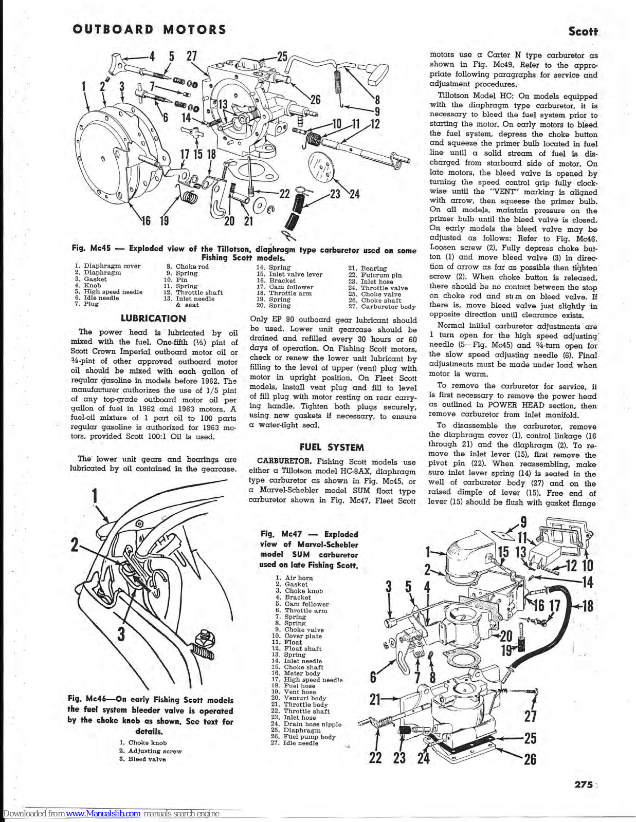
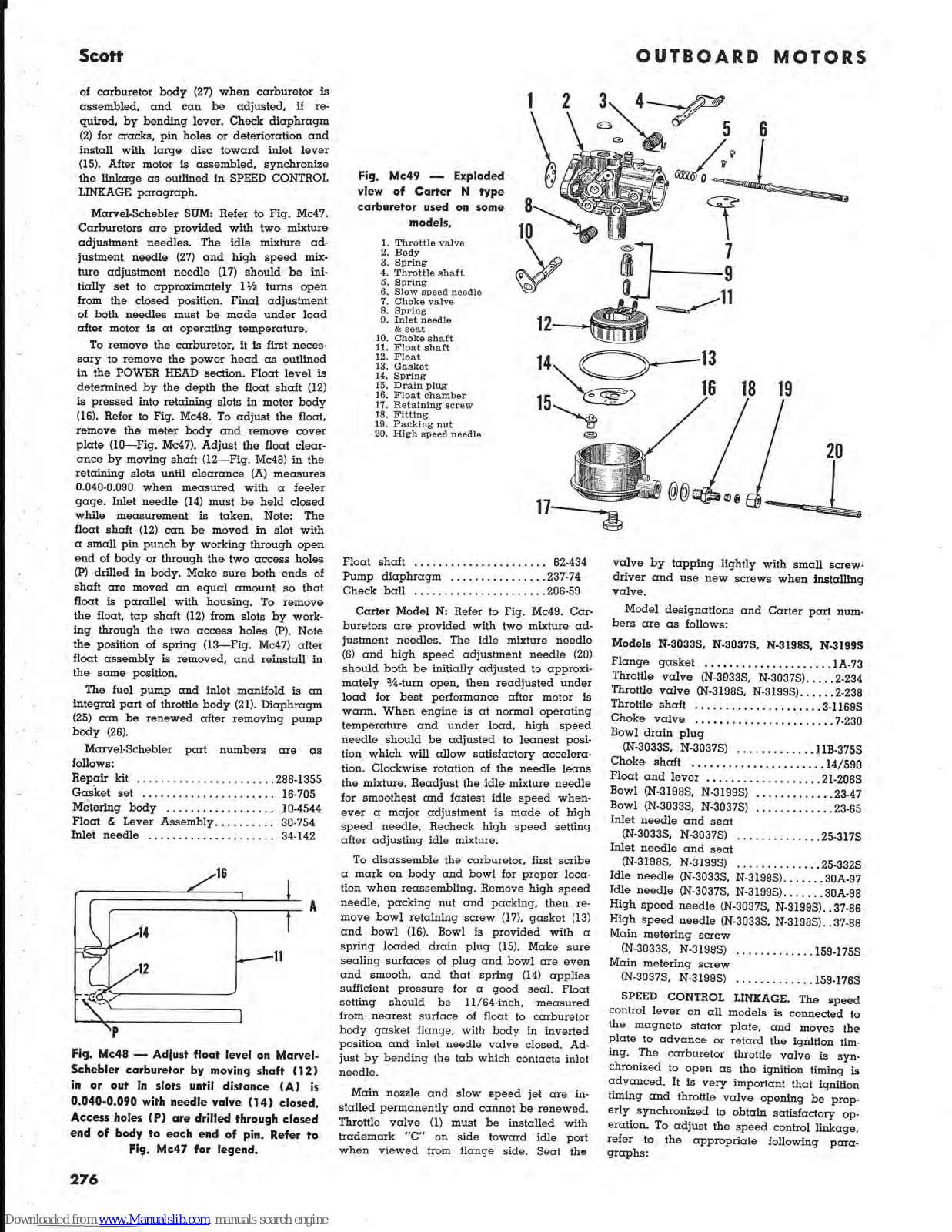
Scott
Loading...
#
000
10 Hp Series
10
2.2
2
112B
114A
120A
120CP
121
121A
16 Hp Series
130
2
200
208
209
222
2
1224HI-12-243
1800
1954-Prices
1955
1960 Series
1961 Series
1962 Series
1963 Series
1964
1967
2001
2002
2003
2005
2005 Bike
2005 Nitrous
2007
2
2007 A
2007 Bike
2
2007 Nitrous Sag-Boy
2008 Bike
2
2008 Ransom
200B
2
2012 BMX
2012 Genius
2013 Bikes
2013 BMX
2013 Genius LT
2014 BIKE
2014 Scale Carbon
2015 PLASMA 5
2015 Spark Series
210A
210B
210C
210D
210E
211A
214a
222A
222B
3
222C
2
222D
3
2009
2010
2013
2014
2220
21205
21210
Loading...
Loading...
Nothing found
1961 Series
Condensed Service Data
10 pgs
2.13 Mb
0
Table of contents
Loading...
Scott 1960 Series, 1961 Series, 1962 Series, 1963 Series Condensed Service Data
...
Scott Condensed Service Data
Download
Specifications and Main Features
Frequently Asked Questions
User Manual
Download
Page 1
Page 2
Page 3
Page 4
Page 5
Page 6
Page 7
Page 8
Page 9
Page 10
Loading...
+
hidden pages
Unhide
You need points to download manuals.
1 point = 1 manual.
You can buy points or you can get point for every manual you upload.
Buy points
Upload your manuals