

Page 1

Copy No.:
Instruction Manual
Model No. : Scott 1800.................
Year of Manufacture : 2005.......
Manufactured by :..........
Document Number : S99999--1........
Issue : 1.....................
Date of Issue : July 2005..............
Page 2

ISSUE NOTE
This is Issue 1; Date of Issue: July 2005
Copyright 2005
Page 3

Table of Contents
III
Scott 1800
TABLE OF CONTENTS
1 INTRODUCTION & SAFETY 1--1...........................................................
1.1 Introduction 1--3....................................................................
1.1.1 Scott 1800 Machine Specifications & Utility Requirements 1--4..........................
1.2 General Safety Guidelines 1--5.......................................................
1.3 Safety 1--6..........................................................................
1.3.1 Main Power Switch 1--6...........................................................
1.3.2 Main Air Disconnect 1--6..........................................................
1.4 Warnings, Cautions & Notes 1--7.....................................................
1.4.1 Warnings 1--7....................................................................
1.4.2 Cautions 1--7....................................................................
1.4.3 Notes 1--7.......................................................................
1.5 On Machine Warnings 1--8...........................................................
1.5.1 Hazards 1--8....................................................................
1.6 Safety Procedures 1--9..............................................................
1.6.1 Appropriate Dress 1--9............................................................
1.6.2 Keep Area Clean 1--9.............................................................
1.6.3 Grease and Oil 1--9..............................................................
1.6.4 Manual Usage 1--9...............................................................
2 INSTALLATION 2--1......................................................................
2.1 Installation Requirements 2--3........................................................
2.1.1 Pre-Installation Requirements 2--3..................................................
2.1.2 Assembly Instructions 2--4.........................................................
2.1.3 Check Punch & Die 2--5...........................................................
2.1.4 Mount Paper Supports 2--6........................................................
2.1.5 Install Plastic Reel 2-- 6............................................................
2.1.6 Set the Plastic Stop Guide 2--8.....................................................
3 OPERATION 3--1.........................................................................
3.1 GENERAL INFORMATION 3 --3........................................................
3.1.1 Before Operating the Machine 3--3.................................................
3.2 Operator’s Controls 3--4.............................................................
3.2.1 Control Panel Layout 3--4.........................................................
3.2.2 Power On/OFF Selector Switch 3--5................................................
3.2.3 Machine Mode Selector Switch 3--5.................................................
3.2.4 Power On Indicator Lamp 3--5.....................................................
3.2.5 Foot Pedal 3--6..................................................................
3.2.6 Main Air ON/OFF 3--6.............................................................
3.2.7 Plastic Advance/Cut Switch 3--6....................................................
3.2.8 Production Sheet Counter 3--7.....................................................
3.2.9 Machine Heater Controls 3--7......................................................
3.2.10 Machine Timers
3--8..............................................................
Page 4

Table of Contents
IV
Scott 1800
3.3 Omron Timer Setting Instructions 3--9................................................
3.4 Scott 1800 Frequently Asked Questions 3--10..........................................
3.5 Tab Bank Layout (Method 1) 3--11.....................................................
3.6 Index Tab Set--Up Procedure (Method 2) 3--13..........................................
3.7 Flow Control Valve Setting 3--17.......................................................
3.7.1 Change or Clean Upper Braking 3--17................................................
3.7.2 Setting Flow Control Valves 3--19....................................................
3.7.3 Testing Flow Control Settings 3--21..................................................
4 MAINTENANCE 4--1......................................................................
4.1 Punch and Die Setting Instructions 4--3...............................................
4.1.1 Punch & Die Removal 4--3........................................................
4.1.2 Reinstallation Punch & Die 4--11....................................................
4.1.3 Setting Left Hand Die 4--15.........................................................
4.1.4 Reinstalling the Punch 4--16........................................................
4.2 Care Of Air Cylinder 4--22.............................................................
4.2.1 Lubrication 4--22..................................................................
4.3 Scott 1800 Spare Parts List 4--25......................................................
4.4 C01--1000 Series Filter -- Regulator Combination 4--26...................................
4.4.1 Installation 4--26..................................................................
4.4.2 Adjustment 4--26..................................................................
4.4.3 Maintenance & Cleaning 4--26......................................................
4.4.4 Vendor Contact Information 4--26....................................................
4.5 304-- 1000 & 2000 Series Lubricators 4--28..............................................
4.5.1 Installation 4--28..................................................................
4.5.2 Oil Adjustments 4--28..............................................................
4.5.3 Tamper Proof 4--28................................................................
4.5.4 Maintenance 4--28................................................................
4.5.5 Part Information 4--29..............................................................
4.5.6 Vendor Contact Information 4--29....................................................
5 PARTS 5-1..............................................................................
5.1 Drag Roller Assembly 5-4................................................................
5.2 Idle and Drive Feed Assembly 5-6.........................................................
5.3 Plastic Feed Air Cylinder Assembly 5-8....................................................
5.4 Punch Assembly 5-10....................................................................
5.5 Heater Press Air Cylinder Assembly 5-12....................................................
5.6 Frame Press Mounting Assembly 5-14......................................................
5.7 Die Assembly 5-16.......................................................................
5.8 Paper Guide Assembly 5-18...............................................................
5.9 Plastic Reel Holder Assembly 5-20.........................................................
5.10 Column Mounting Assembly 5-22..........................................................
5.1 1 Body Mounting Assembly 5-24............................................................
5.12 Air Valve Assembly 5-26.................................................................
5.13 Cover and Plate Assembly 5-28...........................................................
5.14 Leg Extension Assembly 5-30............................................................
5.15 Machine Mounting Rail Assembly 5-32.....................................................
5.16 Bottom Support Rail Assembly 5-34.......................................................
Page 5

Table of Contents
V
Scott 1800
5.17 Guard Assembly 5-36...................................................................
5.18 Controls Mounting Assembly 5-38.........................................................
6 SCHEMATICS 6-1........................................................................
Page 6

1 Introduction & Safety
1--1
Scott 1800 Issue 1
1 INTRODUCTION & SAFETY
Scott 1800 Issue 1
Page 7

1 Introduction & Safety
1--2
Scott 1800 Issue 1
Page 8
1 Introduction & Safety
1--3
Scott 1800 Issue 1
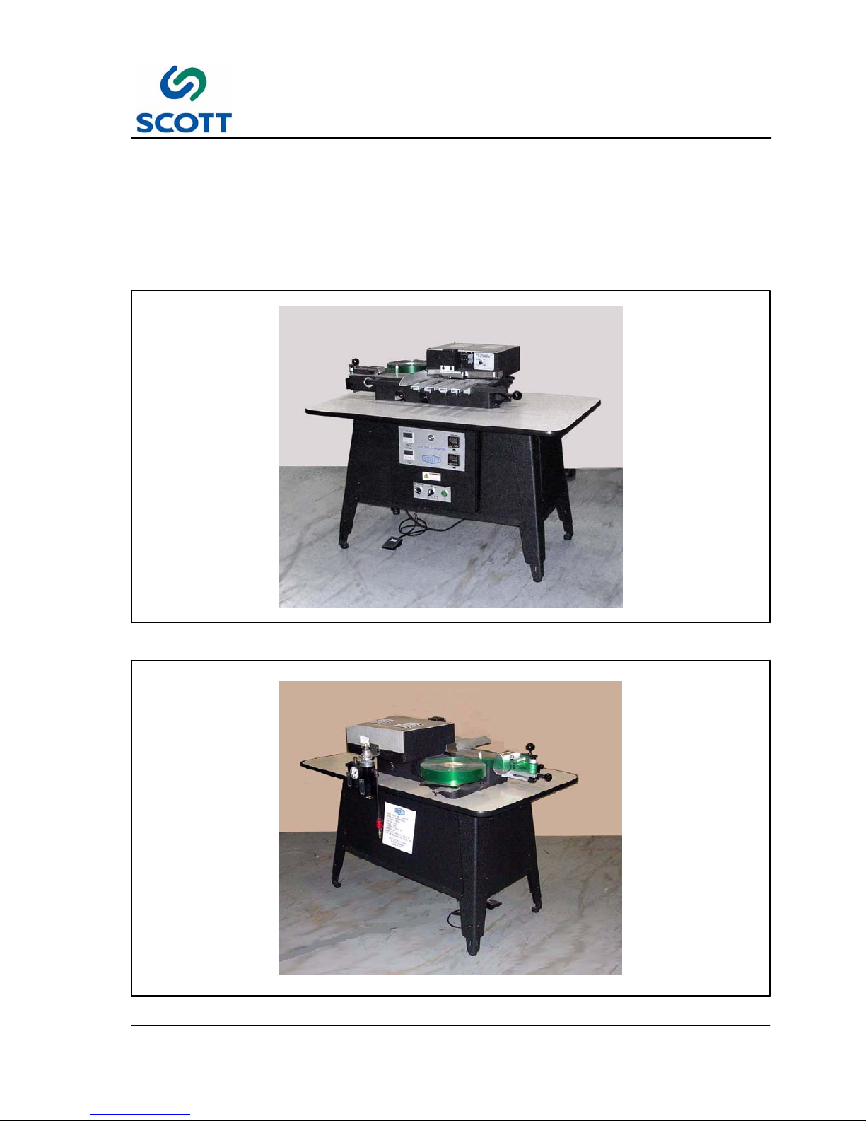
1.1 Introduction
The Scott 1800 Plastic Index Tab Machine is a semi--automatic, manually fed machine for laminating plastic
to index tabs. The plastic is coated with a heat--seal adhesive which is activated when run through the
machine under heat and pressure. The standard width of the plastic is 1--5/8 inches wide.
The Scott 1800 machine can operate at the rate of up to 4,500 sheets per hour.
Fig. 1-1. Machine Front View
Fig. 1-2. Machine Rear View
Page 9

1 Introduction & Safety
1--4
Scott 1800 Issue 1
1.1.1 Scott 1800 Machine Specifications & Utility Requirements
Model Scott 1800t
Speed
Up to 4,500 sheets per hour.
Sheet Size
MIN: 5 1/2” (140MM) LENGTH
MAX: 15” (381MM) WIDE
Plastic Size
MIN: 1” (25.4mm)
MAX: 5.5” (139.7MM)
Paper
32lb. Bond to 25pt.
Electrical Requirements
5AMP 120VAC 50 or 60hz.
Decibel Rating
70dB
Dimensions
Length: 51”
Width: 35”
Height: 38”
Shipping Weight
330lb (150kg)
Warranty
One year against defects in parts
Page 10

1 Introduction & Safety
1--5
Scott 1800 Issue 1
1.2 General Safety Guidelines
Providing a safe working environment for operating your machine is the responsibility of the user. The
suggested precautions, material safety data and other suggestions that follow do not have preference over
the user’s own plant practices, regulations or safety committee recommendations.
Personal injury and equipment damage can be avoided by the continued adherence to the safety features
provided with this machine and in keeping with the necessary governmental requirements. The guarding
and interlocking safety switches have been installed on the machine for the operator’s safety. These items
should be maintained in good working order by the user.
It is assumed that the user’s safety department has established a safety program that is in keeping with a
complete analysis of industrial hazards. Before installing and operating or performing maintenance and
clean--up procedures on the machine, it is suggested that the safety program be reviewed to ensure that it
covers the possible hazards that might occur with the operation of this machine.
Due consideration must be given to those hazards which arise from the presence of electrical power, high
temperature, and cleaning materials used in the operational areas of the machine. Proper installation and
care of protective devices and over--pressure protective equipment should be considered an essential part of
any safety program.
Special lock--out features are to prevent the possibility of applying power to the equipment at any time when
maintenance work is in progress.
In general, personnel should be guided by all basic rules of safety associated with the equipment and the
process. It should be further understood that information contained in this manual does not relieve operating
and maintenance personnel of the responsibility of exercising normal good judgment in operating and care of
the machine and its attendant equipment.
Page 11
1 Introduction & Safety
1--6
Scott 1800 Issue 1
1.3 Safety
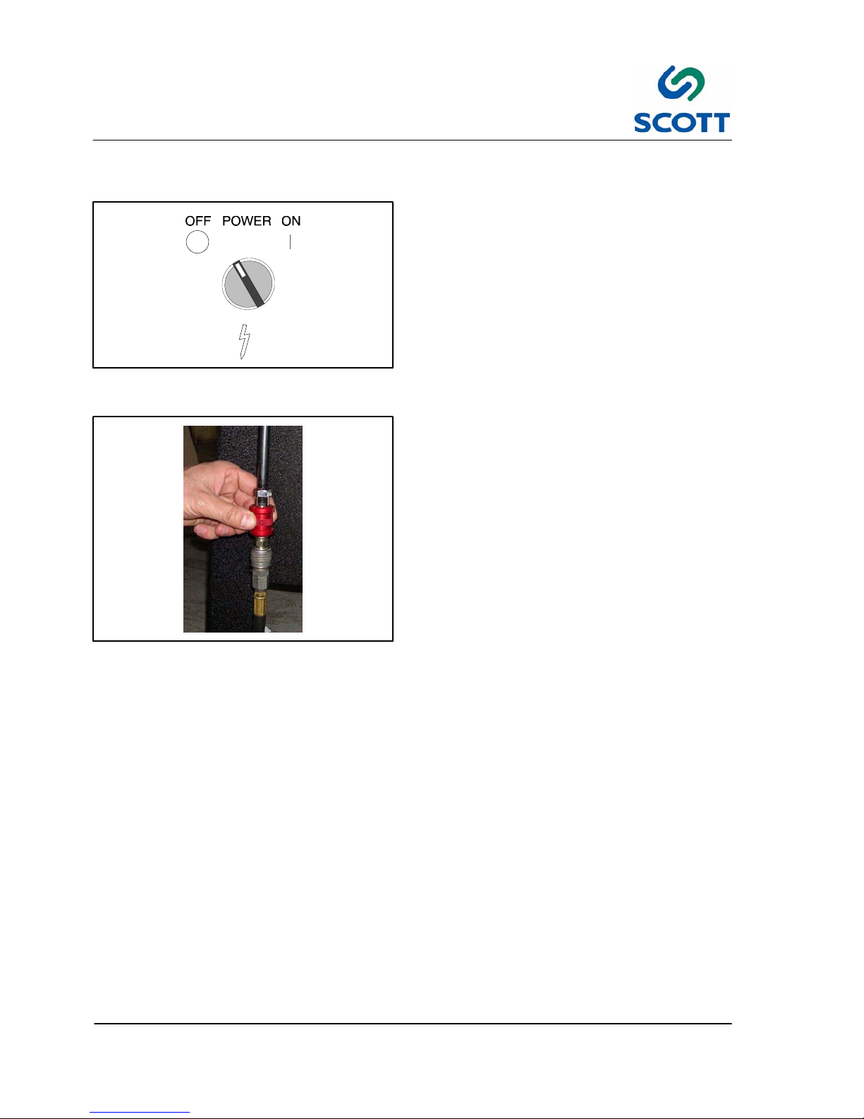
Fig. 1-3. Turn Machine Off Before Making
Adjustments
1.3.1 Main Power Switch
If machine is to be shut down for adjustments or
repairs, turn the power supply to the machine off.
Fig. 1-4. Shut Off Main Air Before Working on
Machine
1.3.2 Main Air Disconnect
Shut off main air before making any machine
adjustments.
Page 12
1 Introduction & Safety
1--7
Scott 1800 Issue 1
1.4 Warnings, Cautions & Notes
In order to emphasize certain areas in the interest of personal safety and a properly operated and maintained
machine, you will encounter the words WARNING, CAUTION, and NOTE throughout this manual.
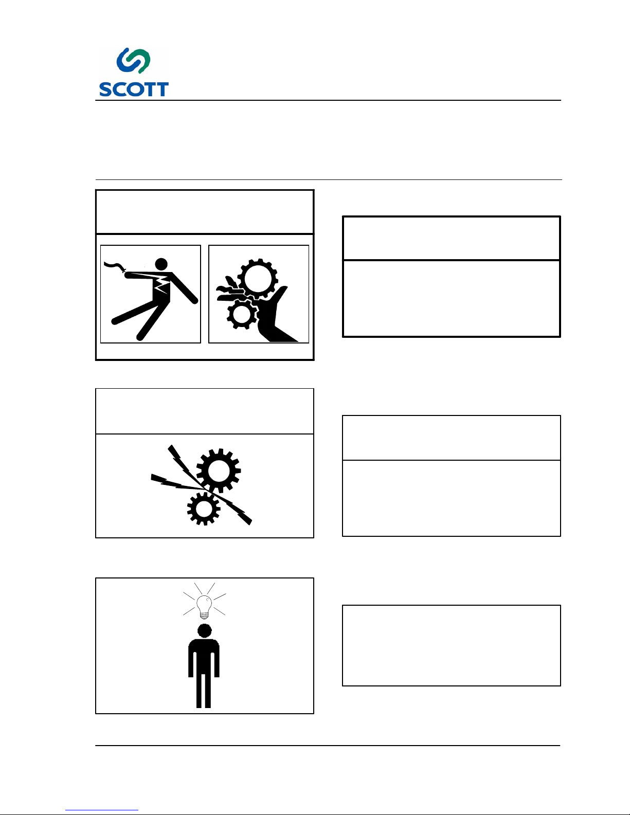
WARNING!
Fig. 1-5. Warnings Indicate Personal Danger
1.4.1 Warnings
AN OPERATING PROCEDURE,
PRACTICE, ETC. WHICH IF NOT
CORRECTLY FOLLOWED, COULD
RESULT IN PERSONAL INJURY OR
LOSS OF LIFE.
WARNING!
CAUTION!
Fig. 1-6. Cautions Indicate Potential Damage to
Equipment
1.4.2 Cautions
AN OPERATING PROCEDURE,
PRACTICE, ETC. WHICH, IF NOT
STRICTLY OBSERVED, COULD RESULT
IN DAMAGE TO OR DESTRUCTION OF
EQUIPMENT.
CAUTION!
Note !
Fig. 1-7. Notes Indicate Essential Information
1.4.3 Notes
An Operating Procedure, Condition,
etc. Which is Essential To Highlight.
Note !
Page 13
1 Introduction & Safety
1--8
Scott 1800 Issue 1
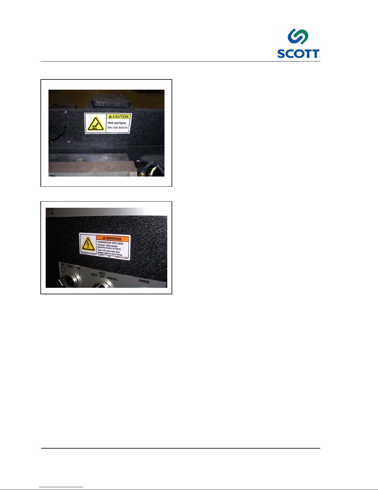
1.5 On Machine Warnings
Fig. 1-8. Hot Surface Hazard
1.5.1 Hazards
Observe Hazard signs.
Fig. 1-9. Voltage Warnings
There are two hazardous voltage warnings. One is
on the main electrical cabinet above the operator’s
controls and the other is on the top cover.
Page 14
1 Introduction & Safety
1--9
Scott 1800 Issue 1
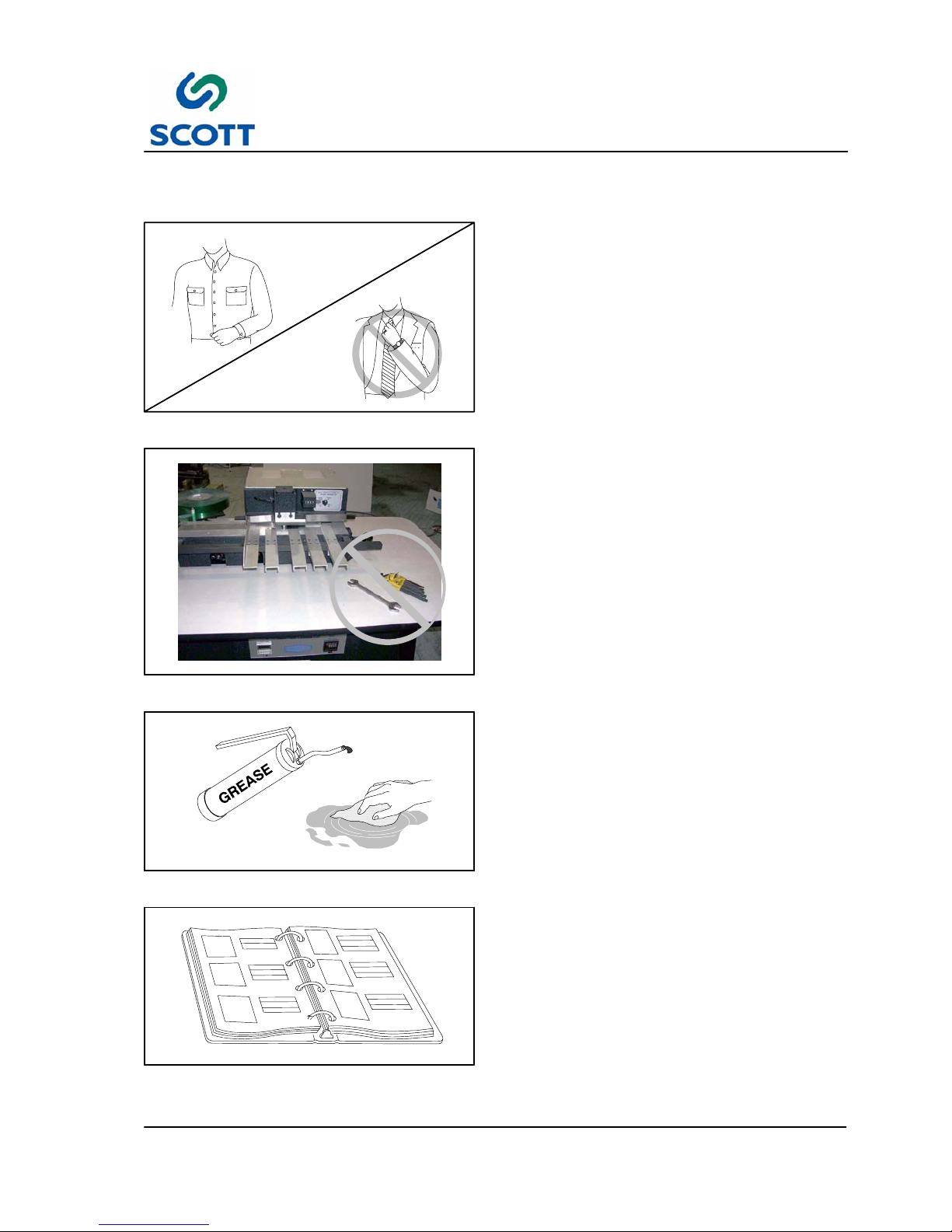
1.6 Safety Procedures
Fig. 1-10. Wear Proper Clothing
1.6.1 Appropriate Dress
Personnel working in the machine operation area
must remove jewelry and neckties. Personnel
must wear clothing appropriate for the work area.
Fig. 1-11. Keep Work Area Clean and Neat
1.6.2 Keep Area Clean
Loose materials, tools and equipment, not
essential to the operation of the machine, must be
removed from the machine work area.
Fig. 1-12. Clean Up Oil and Grease Spills
1.6.3 Grease and Oil
Clean up all oil and grease spills around the
machine work area.
Fig. 1 -13. Read Manuals First
1.6.4 Manual Usage
Read and understand the instructions in the
manual before operating, adjusting or servicing
machine.
Page 15

2 Installation
2--1
Scott 1800 Issue 1
2 INSTALLATION
Scott 1800 Issue 1
Page 16

2 Installation
2--2
Scott 1800 Issue 1
Page 17
2 Installation
2--3
Scott 1800 Issue 1
2.1 Installation Requirements
All procedures in this section provide advance planning and site preparation data for installation of the Scott
1800. Environmental requirements, unpacking instructions, electrical and physical specifications are
included. This information should be used as a reference during the development of site preparation plans
before you install your machine.
If any questions arise while performing any of the following procedures, contact:
Note ! A forklift is required to lift the machine off the shipping skid and place it on the floor.
2.1.1 Pre-Installation Requirements
The environmental requirements of the Scott 1800 must be considered well in advance of the actual
installation. Providing a well suited operating environment will help ensure a trouble free installation process.
Consideration should be given to the following items:
● Power, location and rating of power connections.
● Floor strength
● Level floor
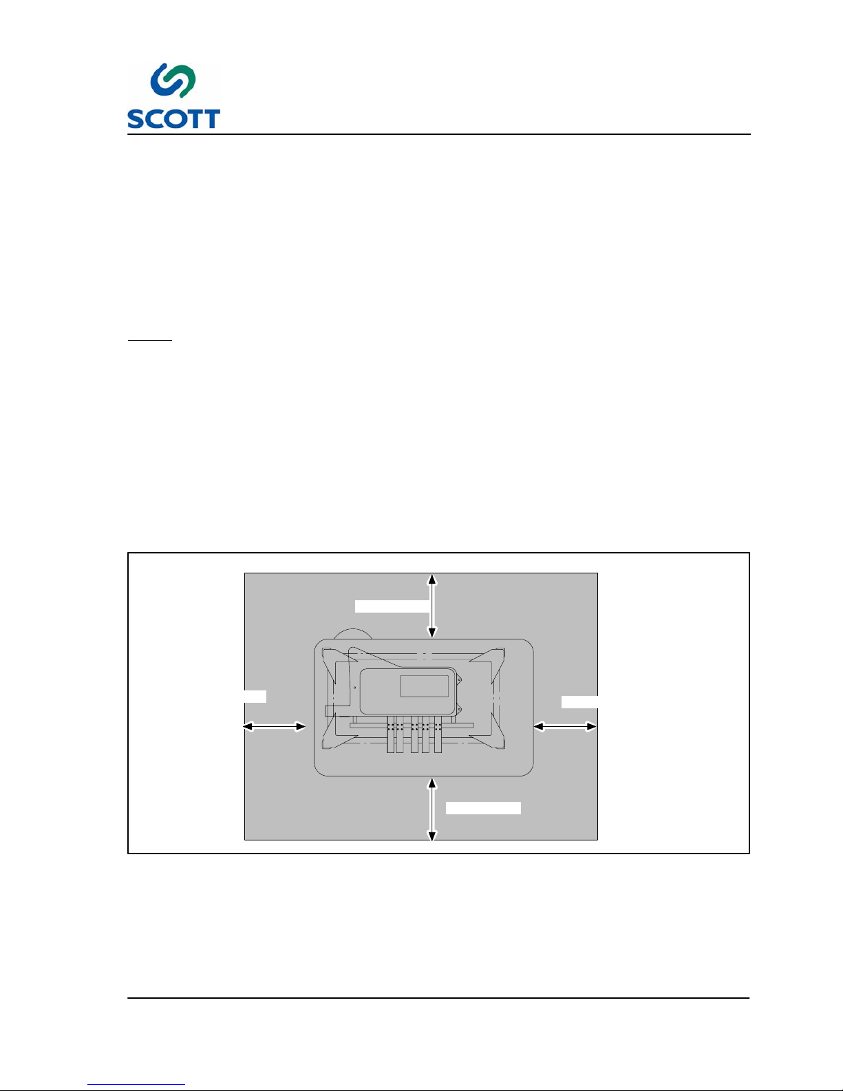
● Adequate space must be provided around all four sides of the machine to permit normal operation and
maintenance procedures. The figure shows the minimum space required.
3’ (914mm)
3’ (914mm)
3’ (914mm)
3’ (914mm)
Fig. 2-1. Scott 1800 Space Requirements
● Space should be allocated near the paper tray for a small table that can be used for small jobs, samples,
etc.
● Provide plenty of space In front of the machine so large jobs can be easily moved in and out with skids or
carts.
Page 18
2 Installation
2--4
Scott 1800 Issue 1
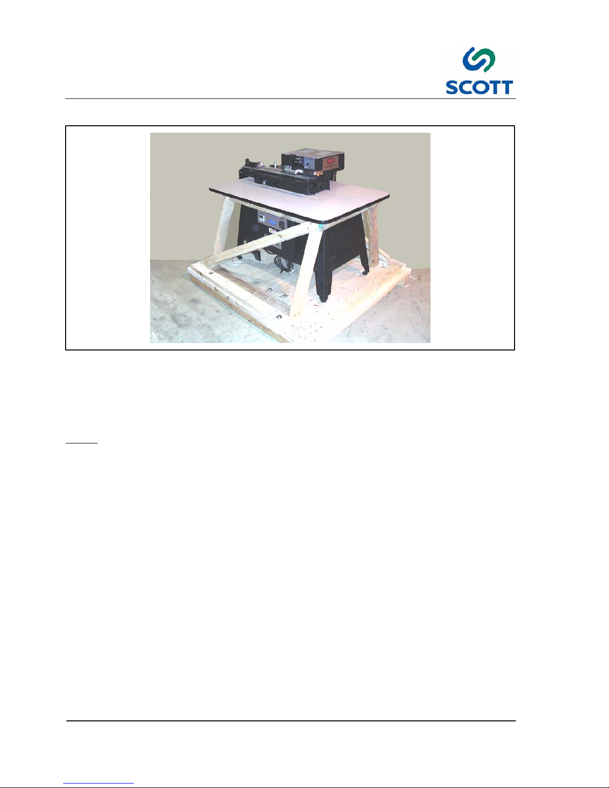
2.1.2 Assembly Instructions
Fig. 2 -2. Machine on Shipping Skid
The machine is shipped assembled.
Step: 1. Remove the machine from shipping skid.
Note ! Now you are ready to bring power to the machine.
DO NOT APPLY AIR PRESSURE TO THE MACHINE AT THIS TIME!!
Step: 2. Plug in the electric cord.
Step: 3. Turn the on/off switch on. The Heat light should come on and both heat controller lights will come
on if the temperature is set high enough.
Step: 4. Set both controllers to 225_F.
After the machine has reached running temperature, the lights on the heat controllers will go on
and off.
Page 19
2 Installation
2--5
Scott 1800 Issue 1
Fig. 2-3. Check Punch and Die
2.1.3 Check Punch & Die
Check the Punch and Die set of the machine. They
may or may not need to be reset, but they do need
to be checked before you start to operate the
machine for the first time, or after any time the
machine has been moved from one location to
another.
Step: 1. Follow the instructions in the
Maintenance section in this manual on
punch and die setting.
Fig. 2-4. Connect Air to Machine
Step: 2. After the dies have been checked and
properly reset if necessary, you may now
connect the air to the machine. Make
sure the pressure regulator is set to 80
P.S.I.
Page 20

2 Installation
2--6
Scott 1800 Issue 1
Fig. 2-5. Mount Paper Supports
2.1.4 Mount Paper Supports
Step: 1. Mount the paper supports, the paper side
guide and the plastic stop to the front of
the machine on the black bar locate
directly in front of the punch and die area.
Fig. 2-6. Place Plastic on Reel Holder
2.1.5 Install Plastic Reel
Step: 1. Place a reel of plastic on the plastic reel
holder on the left side of the machine.
Fold the plastic so the coating is on the
inside.
Note ! The coated side is always on the
outside of the reel.
Step: 2. Thread the machine.
Make sure the plastic goes around the
tension arm coming from the table.
Once you get the plastic started through
the tunnel, you can feed with the manual
toggle switch marked “Plastic
Advance/Plastic Cut”.
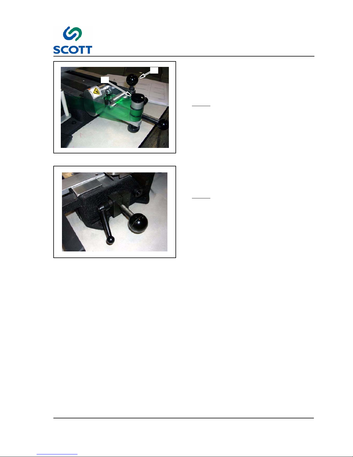
Fig. 2-7. Turn Knob for Tighter or Looser Fold
Step: 3. To adjust a tighter or looser fold, turn the
knurled pin located between the plastic
feed rollers and the drag roller.
Note ! Recommended Tension is three
Plastic Thicknesses.
Page 21
2 Installation
2--7
Scott 1800 Issue 1
A
B
Fig. 2-8. Turn Knob to Adjust Tape Tension
Step: 4. To adjust the tape tension, rotate the
black knob (A) on top of the roller with
the two rubber “0” rings.
This is the drag roller.
Adjust for slight amount of drag.
Note ! This should not need frequent
adjustment.
Step: 5. To adjust the tension between the two
feed rollers by loosening or tightening
tension arm (B) attached to upper feed
roller.
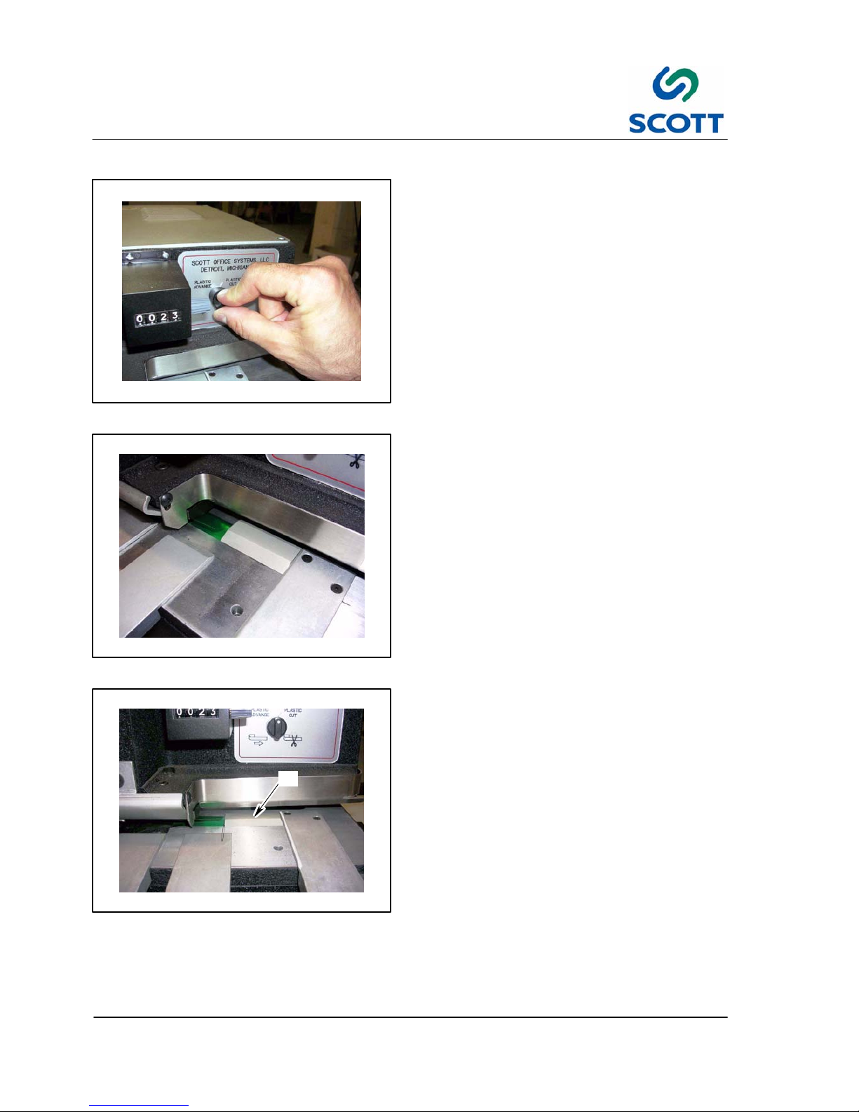
Fig. 2-9. Plastic Size Adjustment (LH Shown)
Step: 6. To adjust the size of plastic, unlock the
pinch lock on the left end of the machine
and set the scale to the desired size.
Note ! Be sure to lock the assembly.
Step: 7. Every time you set the left gauge, you
must set the gauge on the right side of
the machine to the same setting.
This centers the press on the tab you are
making.
If this is not done, you will get bad
bonding since the press will be hitting off
center.
Page 22
2 Installation
2--8
Scott 1800 Issue 1
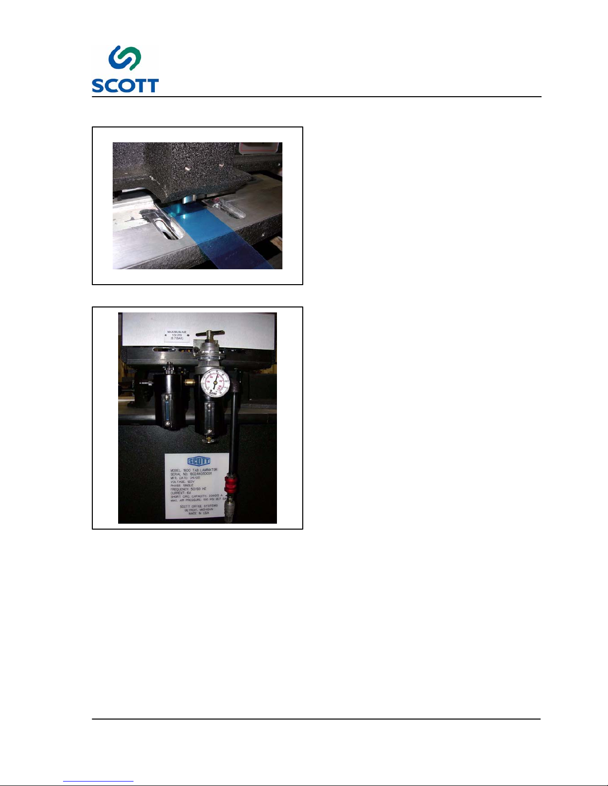
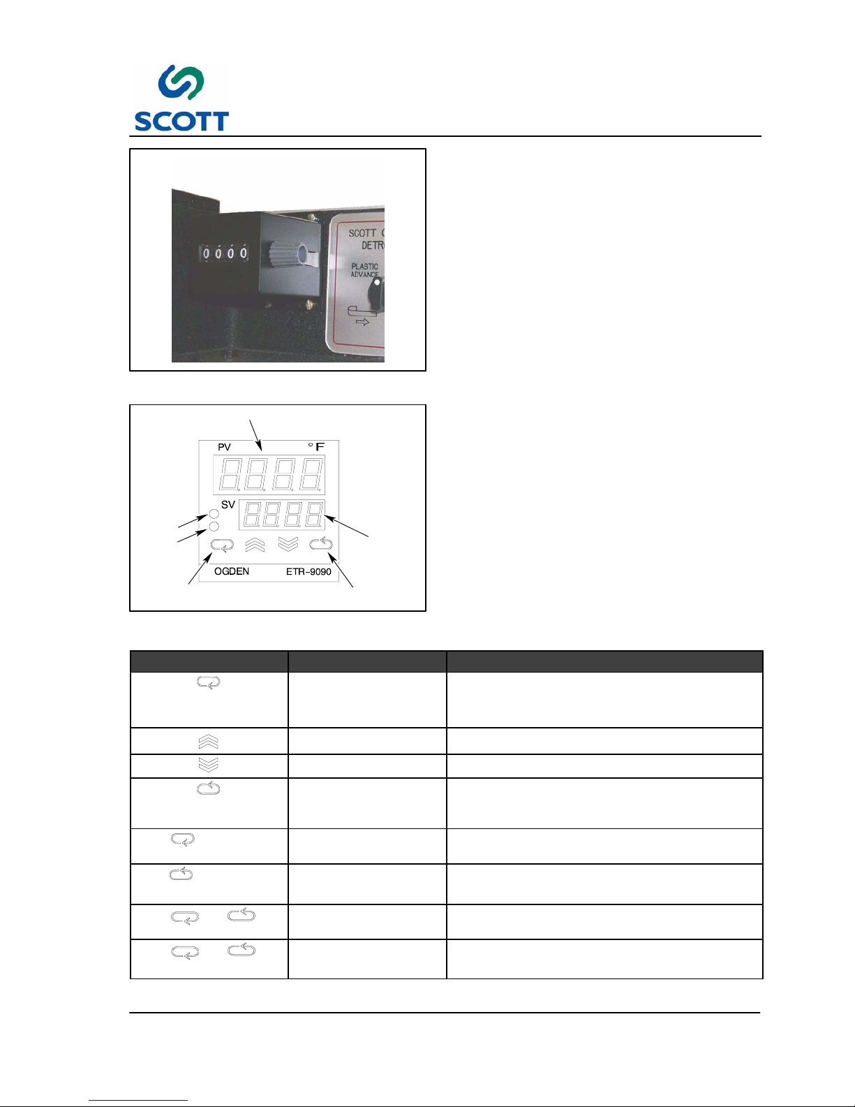
Fig. 2-10. Manually Feed and Cut Plastic
2.1.6 Set the Plastic Stop Guide
To set the Plastic Stop Guide, do the following:
Step: 1. Run tape through the machine past the
punch and die set then, cut off the plastic
with the manual switch.
Fig. 2-11. Feed Piece of Plastic
Step: 2. Feed out a piece of plastic with the
manual feed switch but DO NOT CUT the
plastic.
A
Fig. 2 -12. Bring Stop Guide to End of Plastic
and Add 1/16”, Tighten Guide
Step: 3. Bring the stop guide (A) up to the end of
the plastic and then back it away about
1/32 to 1/16th of an inch. The purpose of
the plastic stop is to help keep the plastic
registered to the same spot on the paper.
Step: 4. Tighten the guide in place.
Page 23

3 Operation
3--1
Scott 1800 Issue 1
3 OPERATION
Scott 1800 Issue 1
Page 24

3 Operation
3--2
Scott 1800 Issue 1
Page 25

3 Operation
3--3
Scott 1800 Issue 1
3.1 GENERAL INFORMATION
3.1.1 Before Operating the Machine
AVOID SERIOUS INJURY OR EQUIPMENT
DAMAGE. RESTRICT OPERATION OF THIS
MACHINE TO TRAINED, QUALIFIED
PERSONNEL ONLY.
EACH OPERATOR SHOULD KNOW THE
LOCATION AND FUNCTION OF ALL
MACHINE STOPPING CONTROLS.
REVIEW MANUAL FOR EMERGENCY
STOP BUTTON LOCATION.
Do not attempt to operate the machine before reading and understanding the manual. Pay close attention to
all WARNINGS, CAUTIONS and NOTES. Failure to do so may cause serious injury and extensive machine
damage.
Read through the inspection and pre--start procedures before starting the machine. Make these checks part
of your routine to insure efficiency and quality during the production run.
Page 26

3 Operation
3--4
Scott 1800 Issue 1
3.2 Operator’s Controls
3.2.1 Control Panel Layout
Fig. 3-1. Control Panel
Fig. 3-2. Operator’s Switches
Page 27
3 Operation
3--5
Scott 1800 Issue 1
Fig. 3-3. Power On/OFF Selector Switch
3.2.2 Power On/OFF Selector Switch
OFF -- Turns Power off to the machine.
ON -- Brings Power to the machine.
Fig. 3-4. Machine Mode Selector Switch
3.2.3 Machine Mode Selector Switch
This selector switch determines the operational
mode of the machine.
AUTO -- When the selector switch is in the Auto
mode, the tab laminating function will operate
when a sheet is inserted into the platen area. By
inserting a sheet into the platen area, contact is
made with a switch which will laminate one tab.
OFF -- Tab laminating cannot be activated in this
mode. This is the standby mode.
MANUAL -- When the switch is in this position, the
switch in platen area is bypassed allowing the tab
laminating operation to be performed using the foot
pedal.
Fig. 3-5. Power On Indicator Lamp
3.2.4 Power On Indicator Lamp
Lamp is illuminated when power (power switch in
ON position) is on.
Page 28

3 Operation
3--6
Scott 1800 Issue 1
Fig. 3-6. Operator’s Foot Pedal
3.2.5 Foot Pedal
The foot pedal is used by the operator to activate
the tab laminating function.
NOTE! Machine Mode switch must be in the
Manual position to operate by foot
pedal.
Fig. 3-7. Main Air
3.2.6 Main Air ON/OFF
Slide the quick disconnect up to allow air to the
machine or down to shut it off.
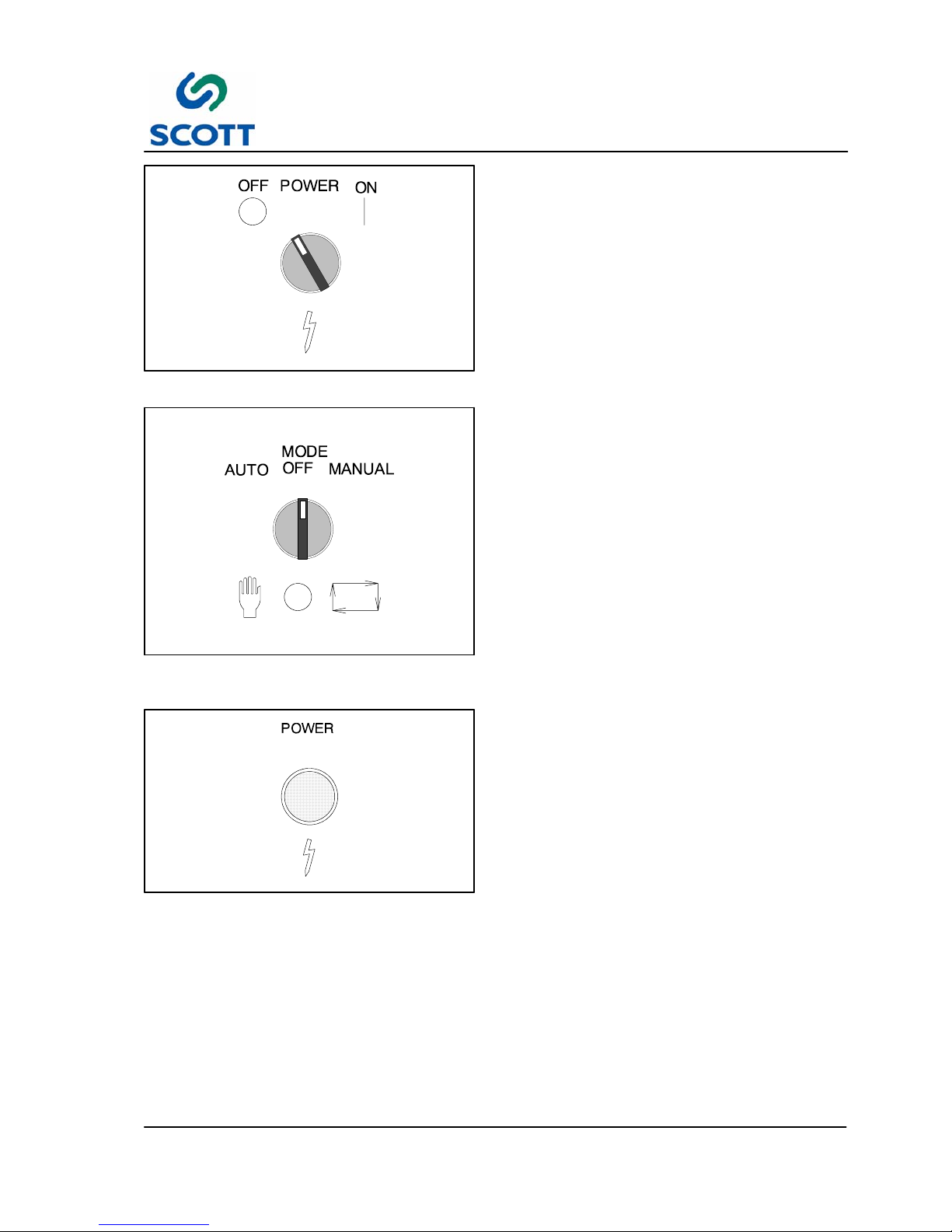
Fig. 3-8. Plastic Advance & Cut Selector Switch
3.2.7 Plastic Advance/Cut Switch
This switch allows plastic to be advanced and cut
manually.
Plastic Advance -- Manually feeds plastic into the
punch and die area.
Plastic Cut -- Activates the punch to cut the
plastic.
Page 29
3 Operation
3--7
Scott 1800 Issue 1
Fig. 3-9. Production Sheet Counter
3.2.8 Production Sheet Counter
Can be reset at any time to keep track of sheets
run.
PROCESS VALUE
SCROLL KEY
RETURN KEY
SET
VAL UE
CON:
Control
Output
ALM:
Alarm
Output
Fig. 3-10. Heater Temperature Control
3.2.9 Machine Heater Controls
Controls the upper and lower platen temperatures
by cycling power to the heaters. The setpoint
temperature is adjusted by using the buttons below
the indicator display.
The controller maintains process parameters when
power is off.
Touch Keys Description Function
Scroll Key Advances the index display to the desired position.
Indexes advanced continuously and cyclically by
pressing this keypad.
Up Key Increases the parameter (Set Point or Other)
Down Key Decreases the parameter (Set Point or Other)
Return Key Resets the controller to its normal status. Also stops
auto--tuning, output percentage monitoring and
manual mode operation.
Press for 6 seconds
Long Scroll Allows more parameters to be inspected or
changed.
Press for 6 seconds
Long Return 1. Executes auto--tuning function.
2. Calibrates control when in calibration level.
Press and
Output Percentage
Monitoring
Allows the set point display to indicate the control
output value in percent.
Press and
for 6 seconds
Manual Mode Execution Allows the controller to enter the manual mode.
This can be used if the sensor fails.
Page 30

3 Operation
3--8
Scott 1800 Issue 1
Fig. 3-11. Plastic Feed and Punch Timers
3.2.10 Machine Timers
Controls the operation of the air valves which
control the operation of the Press and Plastic feed
cylinders as well as the Punch.
Page 31

3 Operation
3--9
Scott 1800 Issue 1
3.3 Omron Timer Setting Instructions
The Omron H3CA Solid--State timers in your Scott 1800 Index T ab Machine control the operation of the air
valves which in turn control the operation of the Press and Plastic feed cylinders as well as the Punch to cut
the plastic. These timers have a wide variety of settings but only a few that are useful to you in the operation
of the machine. Because of the versatility of the timers, and the wide range of time cycles that are offered,
you must make sure that the timers are set within the narrow bandwidth that is useful in the operation of your
Scott 1800.
The two timer units are located on the front of the machine above the Operator’s controls. The one on the
top, controls the Press and Plastic feed cylinders. The normal setting for this timer is as follows:
E
0 0 6 0.1/s
The letters and numbers are set by pushing on the buttons above and below each of the five windows on the
timer. By pressing the button above the window, the letter or number will decrease in value. By pressing the
button below the window, the letter or number will increase in value.
A display at the top of the timers shows what state the timer is in by indicating whether the output is on or off
and how much time is remaining left in the cycle that has been chosen. You will notice that when the
machine goes through its cycle, the display changes rapidly as the machine feeds plastic and then cuts the
piece that was just feed.
Of course, you must also make sure that the lower timer is set to the correct setting. This timer controls the
punch going down to cut the plastic and then returning to its up position. The proper setting for this timer is
as follows:
F
0 0 1 0.1/s
Any other setting than this is generally not acceptable in the operation of the machine. This is the shortest
time possible for the punch to be delayed after the paper has been removed from the machine before it
comes down to cut the plastic. The setting also indicates the amount of time that the punch will be in the
down position. What this translates to is a total time cycle of the punch of twice the indicated time setting, or
in this case, .2 seconds.
The three windows in the middle of the timer will indicate how long the timer is set for. As in the case of the
left timer, when the paper is placed into the machine, the timer will be activated for .6 seconds. During this
time the press cylinder will close the platens on the paper and seal the plastic to it. At the same time, the
feed cylinder will feed out another piece of plastic underneath the sheet that is being laminated. The time of
this timer can be increased to as great as 13/10ths of a second which compares with the original timer in the
older 1800 machines. The setting of 013 on the left timer, and 001 on the right timer will give you a machine
cycle time of 1.5 seconds total duration. This means the operating rate of the machine is 2400 sheets per
hour. With a setting of 006 and 001 (left and right timers respectively), you will have a machine operating rate
of .8 seconds per cycle or 4500 sheets per hour. You will have to decrease the time of the left timer in order
to run plastic lengths of a longer size. This is due to inconsistencies in the plastic length developed by the
faster operation of the machine. Also, the faster you run the machine, the more heat you will need in order to
get a good seal. Keep the heat as low as possible as you can though.
TIMER SETTINGS
PRESS/PLASTIC FEED TIMER PUNCH TIMER
FAST E 0 0 6 0.1/s F 0 0 1 0.1/s
SLOW E 0 1 3 0.1/s F 0 0 1 0.1/s
Page 32

3 Operation
3--10
Scott 1800 Issue 1
3.4 Scott 1800 Frequently Asked Questions
When the plastic is put through your Scott 1800, the heated platens melt the adhesive and bonds it to the
pores of the paper. The adhesive “sets”, giving it a good bond.
Q -- Are there differences in the bonding ability of various paper stocks?
Q -- Why are some papers better for bonding than others?
A-- Because of the construction and the openness of the pores varies. If the pores are closed, the bond will
be poor. If the pores are too open, such as blotter paper, they will not allow a good bond. All papers bond
differently although it is not usually noticeable. Even one side of the paper bonds better than the other since
the paper always has a different construction on each side.
Q -- What are the best bonding papers?
A -- The best are 100% sulfite stocks. A very good bonding paper is 32 lb. and 36 lb. Ledger.
Many index tab producers use this.
Q -- What papers may cause poor bonding?
● Rag content papers
● Coated paper stocks
● Some papers with overall printing
● Varnished papers
● Very close grained smooth paper stocks
● V ery coarse grained stocks
Q -- Why is bonding usually better in summer than winter?
A -- Because in the winter the humidity is low in heated plants. If the plant does not have humidity control, the
paper is dry and the pores have closed. In the summer, the paper picks up moisture and as it swells, the
pores open.
To test if there will be a bonding problem due to humidity: Slightly dampen the sheet and then laminate. Just
a very small amount of dampness is needed. Usually the difference in humidity will not affect the bond
seriously on the “good--bonding stocks” but becomes quite apparent on those which are marginal, such as
rag content paper, etc.
Q -- How to avoid problems?
A -- Always check the first few index tabs before each production run. . This is especially important for the
trade binder who gets all types of paper stocks from their printer customers.
Q -- Which way should the grain of the paper run for best bonding?
A -- For best results, the grain should be parallel to the binding edge of the sheet, on an 11 x 8--1/2” sheet,
the grain should be the 11” way. When a tab is laminated across the grain, it may warp slightly.
Page 33

3 Operation
3--11
Scott 1800 Issue 1
3.5 Tab Bank Layout (Method 1)
Choose a scale to allow you to divide the sheet into equal tab sizes. This example shows the page divided
into nine equal tabs. By changing the angle of the ruler, you can establish any number of tabs on any size
sheet of paper.
The following procedure will allow you to divide any size sheet into any number of equal size tabs.
Step: 1. First, draw two parallel lines, one at the top and one at the bottom of the paper. On an eleven inch
sheet, you will usually provide a half inch margin on both sides of the paper. These are the top and
bottom lines on the illustration attached.
Step: 2. Place a ruler across these two lines.
Step: 3. Use the lowest number on the ruler on one line and any number on the ruler which will easily divide
evenly into the number of divisions you want on the other line. The angle of the ruler is not
important.
Step: 4. Place a mark on the sheet at each division that equally divides the sheet.
For example, using an 11” sheet, if you wish to divide the sheet into 12 equal tabs, place the 0 on
one line and the 12 on the other. You use the twelve because it is a convenient unit to divide the
sheet into twelve equal parts by placing a mark at each of the inch markings.
Page 34

3 Operation
3--12
Scott 1800 Issue 1
1/2” MARGIN
1/2” MARGIN
PLASTIC
3/8”3/8”
Fig. 3-12. Method to Evenly Divide Sheet for Tabs
Above (Fig. 3-12. ) is another example.
The sheet is divided into nine equal tabs. By placing the zero on one side and the nine on the other, you are
able to make nine tabs. You will notice that this is not a standard inch ruler. Y ou may use any ruler that has
evenly divided scales that will allow you to easily divide the sheet into the number of tabs you want.
Continue the layout sheet by drawing lines up to the tab side of the sheet from the marks you made. You
may use a plastic triangle with one edge of the triangle against the edge of the sheet, or set the sheet up on
a light table or drafting table to make sure that the lines are equally spaced. The more care you take with the
layout sheet, the more accurate your tabs will be.
The lines drawn from the marks to the tab side of the paper represent the tab size. This is the space required
to make the tab, and all of the text or graphics must fit into this area. If you are plastic laminating your tab,
you will need to make the plastic size an additional 3/4” greater than the tab size. Measure the distance
between the two lines that represent the tab, and then add 3/4” for the plastic tab.
Page 35

3 Operation
3--13
Scott 1800 Issue 1
3.6 Index Tab Set--Up Procedure (Method 2)
Step: 1. Make a layout sheet of the job to be laminated. Use either the preset tab sizes or angle rule
method.
Step: 2. From your layout sheet, determine the size of the finished tab. Add an additional 3/4” for the plastic
size (3/8” on each side of the tab).
Fig. 3-13. Set Left Guide to Plastic Size
Step: 3. Set the left gauge to the plastic size you
want to produce. With the Plastic
Advance/Cut toggle switch on instrument
panel, feed one piece of plastic making
sure you hold the toggle feed switch long
enough so that it will feed a full length of
plastic.
Step: 4. Cut the piece by turning the switch
toward the Cut side.
Fig. 3-14. Compare to Layout Sheet
Step: 5. Take the piece of plastic out of the
machine and compare its size to that on
the layout sheet. Adjust the plastic size
gauge if the plastic is not exactly what
you wanted.
Page 36

3 Operation
3--14
Scott 1800 Issue 1
Fig. 3-15. Set Right Hand Guide to Same as Left
Hand Guide
Step: 6. After the correct plastic size has been
obtained, set the right hand gauge to the
same reading as the left hand gauge. For
example, if you are making a 3” piece of
plastic, both the left hand and right hand
gauges should be set at 3”. The right
hand gauge centers the press on the size
you are making and insures that it will be
properly sealed.
Fig. 3-16. Set Plastic Stop
Step: 7. Use the “Plastic Advance/Cut” switch to
manually feed one piece of plastic
without cutting the plastic at this time.
Step: 8. Take the Plastic Stop Guide and position
it on the bar by moving it so that it just
touches the edge of the uncut piece of
plastic.
Step: 9. Back the Plastic Stop Guide away from
the plastic by 1/32”. This insures that you
will have good plastic registration on your
index tab sheet.
A
B
Fig. 3-17. Align G uide with Tab Edge Mark
Step: 10.Use the “Plastic Advance/Cut” switch to
cut the plastic. Leave the cut piece of
plastic in the machine.
You will repeat the following steps as
often as necessary for each of the tab
positions.
Step: 11.Set the Paper Side Guide by using the
layout sheet or by approximating the
position you wish to apply the plastic to
the paper.
Step: 12.With your layout sheet, line up the mark
that indicates the left edge of the
laminated tab (A) with the notch (B) in the
guide that guides the paper into the
sealing area.
Step: 13.The guide height should be set just below
the punch when it is fully retracted.
Page 37

3 Operation
3--15
Scott 1800 Issue 1
B
Fig. 3-18. Move Paper Guide to Contact Edge of
Paper
Step: 14.Move the Paper Side Guide (C) into
contact with the paper’s left side.
Step: 15.Lock the Paper Side Guide on the bar.
Be sure the Paper Side Guide is locked
squarely onto the bar.
Step: 16.Attach the remaining Paper Tray
Supports to the bar between the Plastic
Stop Guide and the Paper Side Guide.
Fig. 3-19. Insert Paper In Laminating Area
Step: 17.Set the cycle switch to “Auto”.
Step: 18.Using a piece of paper the same size as
the job to be laminated, insert the paper
into the machine to apply the plastic to
the tab area.
Fig. 3-20. Compare Tab with Layout Sheet
Step: 19.Compare this with your layout. Adjust the
Paper Side Guide as necessary.
Page 38

3 Operation
3--16
Scott 1800 Issue 1
Fig. 3-21. Laminate Sheets
Step: 20.After the desired position has been
obtained, laminate all the sheets for this
position of your job.
Step: 21.Repeat steps 10 to 16 until finished.
Page 39

3 Operation
3--17
Scott 1800 Issue 1
Fig. 3-22. Flow Control Valves
3.7 Flow Control Valve Setting
The Scott 1800 has incorporated two flow control
valves to help regulate the plastic piece size
consistency. These two valves adjust the stroke
speed of the plastic feed cylinder to assure an
even stroke in and out to give you consistent
plastic piece size with a variance of no greater than
1/32nd of an inch.
There are two main reasons for the plastic pieces
not to be of uniform length. The first reason is that
the flow control valves are improperly adjusted.
The second reason is an inadequate amount of
brake pressure being applied to the upper feed
roller.
When the flow control valves are improperly
adjusted, the plastic piece size tends to be shorter
than the desired length. When the breaking
pressure on the upper plastic feed roller is
inadequate, the plastic pieces tend to be longer
than the desired length.
Fig. 3-23. Upper Brake is Located Under Gear
Guard
3.7.1 Change or Clean Upper Braking
To correct plastic size that is too long:
It is necessary to change or clean the upper feed
roller braking fiber and the surface that the brake
rides against.
The following are the steps for cleaning and/or
changing the braking fiber on the upper plastic
feed roller.
Page 40

3 Operation
3--18
Scott 1800 Issue 1
Fig. 3-24. Remove Guard
Step: 1. Remove the gear guard.
Fig. 3-25. Remove Screw on Shaft
Step: 2. Remove the screw on the end of the
shaft.
Step: 3. Remove the washer, spring, and the
second washer if there is one on your
assembly.
Fig. 3 -26. Remove Fiber Brake
Step: 4. Remove the fiber brake assembly.
Step: 5. Inspect the brake assembly.
If there is oil or grease on the brake fiber,
remove it with sand paper. Wait for about
five minutes to see if any more oil will
reappear on the surface of the fiber.
Sand again if more does.
If the oil persists, the replacement of the
brake is necessary.
Page 41

3 Operation
3--19
Scott 1800 Issue 1
Fig. 3-27. Clean Surface of Roller
Step: 6. Inspect and clean the surface of the
upper plastic feed roller that the brake
rides against.
Step: 7. Remove all grease and oil that may be
on this surface.
Step: 8. Reassemble the brake assembly to the
plastic feed roller by reversing steps 1, 2,
and 3.
Step: 9. Make sure that the upper feed roller has
resistance when turned after it has been
reassembled.
NOTE! If the roller turns too freely, you may
need to add on additional washer to
increase the brake pressure.
A B
Fig. 3-28. Flow Control Valves
3.7.2 Setting Flow Control Valves
Next are the steps to set the flow control valves. It
is important that you are able to hear the cylinder
as it goes outward and hits the stop which gives
you the plastic length (the left hand adjustment for
the plastic piece size).
The stroke of the cylinder should be set as slow as
possible so that it will go out to the stop, then stop
at the stop, and return to its rest position within the
cycle time of the machine. The return stroke will be
set a little faster than the out going stroke, but both
should be set as slow as possible yet fast enough
for them to complete their job.
The flow control valves are located underneath the
lower casting, on the press cylinder. The flow
control valve (A) on the left, controls the outgoing
stroke speed. The flow control valve (B) on the
right controls the return stroke speed. These
valves may differ on different machines but all of
them operate on the same principal. The speed of
the stroke is made faster by turning the valve
counter--clockwise and slowed down by turning the
valve clockwise.
Different valves lock the adjustments in different
ways. Be sure to lock the adjustment in place after
you are satisfied with the results.
Page 42

3 Operation
3--20
Scott 1800 Issue 1
Fig. 3-29. Set Plastic Piece Size to 5--1/2 Inches
Step: 1. Set the plastic piece size to 5--1/2 inches.
Step: 2. Remove the plastic from the machine.
Step: 3. Cycle the machine through one time
while watching and listening to the stroke
of the cylinder.
A
Fig. 3-30. Adjust Stroke Valve
Step: 4. Adjust the left (A) flow control valve to
where you can just hear the cylinder hit
the stop on its outgoing stroke.
Step: 5. Cycle the machine through a few times in
a row. Listen for the cylinder hitting the
stop on the outgoing stroke. If it sounds
as if it is hitting harder on the second and
third stroke, open the valve about 1/4
turn.
Step: 6. Cycle the machine through again and
watch the return stroke of the cylinder.
B
Fig. 3-31. Adjust Return Valve
Step: 7. Adjust the right (B) flow control valve so
that the cylinder comes back and seats
itself against the stop before you can
begin the next cycle. Its return speed
should be a little faster than the outgoing
stroke speed.
Page 43

3 Operation
3--21
Scott 1800 Issue 1
3.7.3 Testing Flow Control Settings
Step: 1. Thread plastic into the machine and manually feed it forward.
Step: 2. Cycle the machine through three or four times and compare the plastic pieces. Keep the pieces in
order as you cycled them through.
a. If all the pieces are the same size except the first piece, and the first piece is shorter, open the left
flow control valve by a slight amount. Repeat as necessary.
b. If each succeeding piece is longer than the preceding piece, open up the right flow control valve 1/8
turn and try again.
c. If each succeeding piece is still longer after you have executed setting above , make sure that the
cylinder is hitting the stop on the outgoing stroke (open left valve to increase speed of the outgoing
stroke).
d. If the plastic sizes seem to vary randomly in length, check the upper plastic feed roller brake
assembly and start over from Step 1.
If the above steps cannot help you after repeating them a couple of times, there may be further problems.
Contact
Page 44

4 Maintenance
4--1
Scott 1800 Issue 1
4 MAINTENANCE
Scott 1800 Issue 1
Page 45

4 Maintenance
4--2
Scott 1800 Issue 1
Page 46

4 Maintenance
4--3
Scott 1800 Issue 1
Fig. 4-1. Punch and Die Assembly
4.1 Punch and Die Setting
Instructions
The Punch and Die set is the heart of the machine
and will need to be sharpened on occasion.
This will necessitate the removal of various
components in order to remove the Punch and Die
set for sharpening. It is also necessary that the
Punch and Die set be reinstalled properly so that
you will decrease your down time and reduce your
sharpening cost.
Note !Preheat the machine for 2 hours prior to
setting the punch and die to allow for
proper operating clearances.
Note !If you have just received your machine,
or have just moved it from one
location to another, it will be
necessary to check the Punch and Die
set to make sure that they are cutting
correctly and are not hitting each
other.
Fig. 4-2. Remove Paper Trays
4.1.1 Punch & Die Removal
The following is the procedure for the removal and
reinstallation of the Punch and Die set.
Note !Make sure that Main Air Supply is off
before making adjustments the
machine.
Step: 1. Turn off the air supply to the machine.
Step: 2. Remove the Paper Trays.
Page 47

4 Maintenance
4--4
Scott 1800 Issue 1
Fig. 4-3. Remove the Cylinder Guard
Step: 3. Remove the Cylinder Guard.
Fig. 4-4. Remove the Chip Chute Deflector
Step: 4. Remove the Chip Chute Deflector.
Fig. 4-5. Remove the Punch Assembly Guards
Step: 5. Remove the three Punch Assembly
Guards.
Page 48

4 Maintenance
4--5
Scott 1800 Issue 1
Fig. 4-6. Remove the Tunnel Cover
Step: 6. Remove the Tunnel Cover.
Fig. 4-7. Remove the Guide Spring
Step: 7. Remove the Guide Spring.
Page 49

4 Maintenance
4--6
Scott 1800 Issue 1
Fig. 4-8. Remove Plastic Guide -- Keep Shims
with Guide
Step: 8. Remove the plastic opener springs.
Step: 9. Reattach hardware to opener and shim
stack to keep shim with opener.
Note !There may or may not be shims that
were used in the set up of this part.
Keep shim stack with particular
opener spring. (ie. Keep RH shim
stack with RH opener)
Fig. 4-9. Remove Punch Cap
Step: 10.To remove the punch cap, remove two of
the screws diagonally opposing each
other.
Step: 11.Remove the remaining two screws
keeping the end cap level as you remove
the screws.
Page 50

4 Maintenance
4--7
Scott 1800 Issue 1
Fig. 4-10. Remove Punch Springs
Step: 12.Remove the long spring from inside the
Punch. There is an additional shorter
spring inside the Punch which you may
or may not want to remove.
Fig. 4-11. Remove Punch
Step: 13.Insert a finger into the hole of the Punch
and pull the punch straight up and out of
the cylinder.
CAUTION
! Do not use anything metallic in
helping to remove the Punch. If you
are unable to remove the Punch by
pulling it straight up, try applying
about 20 P.S.I. of air pressure to the
machine. This will help you to pull the
punch out of the cylinder. If you still
can’t remove the punch proceed to
Step: 16. and then repeat this step.
Page 51

4 Maintenance
4--8
Scott 1800 Issue 1
A
B
Fig. 4-12. Remove Piston Packing and O --Ring
Step: 14.Remove Piston Packing (A) and O Ring
(B).
You may need a small thin blade screw
driver to assist you in their removal.
Fig. 4-13. Remove the Plastic Guide In Front of
the Dies
Step: 15.Remove the plastic guide that is in front
of the dies.
Note !Be careful not to loose the small
springs in the guide.
Page 52

4 Maintenance
4--9
Scott 1800 Issue 1
C
D
Fig. 4-14. Remove the Dies
Step: 16.Remove the four screws (C) holding the
two dies (D) to the lower casting. The
screws are located underneath the lower
casting.
Step: 17.Remove the two dies.
Fig. 4-15. Inspect the Punch and Dies
Step: 18.Inspect the Punch and Dies to make sure
that the cutting edges are not nicked,
scratched, or rounded off.
If so, they will need to be sharpened
before they are reinstalled into your
machine.
If you will also examine the Punch you will notice
that the cutting edge of the punch is angled. The
back edge away from the radius is higher. This is
important in the setting of the proper height of the
punch when you go to set the dies.
Page 53

4 Maintenance
4--10
Scott 1800 Issue 1
F
E
Fig. 4-16. Differences Between Left and Right
Guide
You will notice if you lay both of the dies next to
each other that there is a difference between the
left (E) and right (F) die. The obvious difference is
in the appearance of the dies themselves. The left
die is the one that has the beveled edge on the
one side.
You will also notice that the right die is shorter than
the left die by about .025 inch. This is to allow the
plastic to flow from the left die to the right die
without jamming.
Page 54

4 Maintenance
4--11
Scott 1800 Issue 1
4.1.2 Reinstallation Punch & Die
The following is the procedure to reinstall the Punch and Die set. There are four main steps in the setting of
the Punch and Dies. The first one is to make sure that the punch, dies, and the die pocket are free from any
oil, plastic, or any other foreign matter. Number two is to set the side guide against the punch so that it will
not have any radial (twisting) motion as it goes into the dies. The last two steps are to set the right die first
and the left die last.
A
B
Fig. 4-17. Loosen Screws and Set Punch Guide
4.1.2.1 Setting Punch Side Guide
Step: 1. Make sure the die pocket, the punch and
dies, and all the relating parts are clean.
Step: 2. To adjust the guide, loosen the two
screws (A) and push the guide sideways
into the punch (B) and tighten the two
screws.
Note !There should be enough resistance
from the guide into the punch that the
punch cannot fall to the bottom of the
cylinder under its own weight.
The guide should be set tight enough so that you
cannot twist the punch sideways, yet loose enough
so that you are able to move the punch up and
down in the cylinder.
If pushing the guide in and tightening down the
screws does not allow the guide to get close
enough to the punch to keep it from twisting, then
you will have to leave the screws tight and lightly
tap on the right edge of the guide to bring it closer
to the punch to keep it from turning. The screws
are left tight so that the guide will not bounce away
from the punch. If the guide is too tight, start again.
Caution ! It is very important that the punch not have any radial movement when it enters the dies.
Severe damage may result to the punch and/or the dies. Make sure when you are setting the
side guide that the radius of the punch is facing toward you as you face the machine.
Page 55

4 Maintenance
4--12
Scott 1800 Issue 1
Fig. 4-18. Place the RH Die in the Pocket
4.1.2.2 Setting Right Hand Die
After the side guide is properly set, the next step is
to set the right side die. You will need a screwdriver
with a small blade and about a six inch or longer
shank. You will also need a 3/16th Allen wrench
and some Mylar to check the cutting.
Step: 1. Remove the punch from the Punch
Cylinder to give you room to put the die
into the pocket.
Step: 2. Place the right die in the die pocket on
the right side with the radius of the die
toward you on the left hand side.
Step: 3. Put the washers over the screws and put
the screws into the die from underneath
the lower casting. Do not tighten the
screws at this time.
Step: 4. Push the die toward the back right corner
of the die pocket.
The die may be maneuvered by using your left
hand to move the screws underneath the casting
and by placing the blade of the screwdriver into the
screw hole of the die with your right hand and
moving them both simultaneously.
CAUTION
! Be careful not to let the screwdriver
come into contact with the cutting
edge of the punch or the die. Severe
damage could result.
Fig. 4-19. Insert Punch Into the Cylinder
Step: 5. Insert the punch into the cylinder and
position it so that the radius is facing
toward you.
Step: 6. Push the punch down so that it appears
out of the bottom of the cylinder. Be sure
that the punch does not hit the die as it
comes out of the cylinder.
Page 56

4 Maintenance
4--13
Scott 1800 Issue 1
Fig. 4-20. Punch Height Should Be Slightly
Above Edge of Die (Shown Out of Place)
Step: 7. Position the height of the punch so that
the back cutting edge is just below the
top of the die. This is know as the “Punch
setting position”.
Note !Punch and Die shown removed from
punch cylinder for clarity.
Fig. 4-21. Set Die to Punch (Shown Out of
Place)
Step: 8. Set the die to the punch. This is
accomplished by positioning the die so
that the edges of both the punch and die
are up against each other.
Page 57

4 Maintenance
4--14
Scott 1800 Issue 1
Fig. 4-22. Use a Screw Driver to Hold Die in
Position
Step: 9. Carefully place the flat part of the
screwdriver blade onto the center of the
die between the two screw holes. Place
the shank of the screwdriver up against
the bottom part of the upper casting. Use
the screwdriver to hold the die down
against the bottom of the lower casting at
all times during the tightening of the
screws. If the die moves when you place
the screwdriver on top of the die, go back
to step eight and then continue.
Step: 10.Hand tighten the two screws that hold the
dieinplace.
Step: 11.While keeping the die clamped down,
carefully begin tightening the screws with
the Allen wrench. Y ou should work back
and forth between the two screws
keeping the torque as even as possible.
Note !To over tighten one screw more than the
other can cause the die to twist and
will either make the punch hit the die,
or keep it from cutting.
Step: 12.After the screws are tight, remove the
screwdriver.
Fig. 4 -23. Carefully Lift and Slowly Lower
Punch
Step: 13.Carefully lift the punch up above the die
and bring it SLOWLY back down to the
bottom of its stroke. If the punch hits or
rubs against the die, you will need to
reset the die again. This means going
backtostep8.
As long as the punch is not hitting the die on the
downward stroke, you are now ready to see if it will
cut the Mylar.
Page 58

4 Maintenance
4--15
Scott 1800 Issue 1
Fig. 4-24. Test Punch to See if will Cut Mylar
Step: 1. Place a piece of Mylar film over the top of
the die. Make sure that the plastic is not
folded in half.
Step: 2. With the Mylar over the die, bring the
punch down to see if it will cut the Mylar.
The punch should pass through the Mylar
with little or no difficulty.
If it is hard to push the punch through the
plastic, you will need to reset the die. Go
to step eight above.
Fig. 4-25. Tighten Mounting Screws If Cut is
Clean
Step: 3. If the plastic is cut cleanly, you should
make sure that the die is clamped down
tight so that it will not move in normal
operation.
Step: 4. After you have checked the die to make
sure the screws are tight, recheck the
cutting ability of the die and make sure
that the punch doesn’t hit the die.
Fig. 4-26. Set Left Hand Die
4.1.3 Setting Left Hand Die
After you have made sure that the right die is
cutting properly, it is time to set the left die. The
procedure is the same as the right die except in
this case you may use your hand to clamp the die
in place as it is being tightened down instead of
using a screwdriver. Make sure that you are
keeping the die clamped down at all times as you
are tightening the screws.
Note !Lift the Punch clear of the cutting area
before setting the left die.
After both dies are set and are properly cutting, it is
time to reassemble all of the parts removed.
Basically you will reverse the order of the first
sixteen steps in these instructions.
Page 59

4 Maintenance
4--16
Scott 1800 Issue 1
Fig. 4-27. Remove Punch From Cylinder
4.1.4 Reinstalling the Punch
Make sure that the piston packing and the 0--ring
are lubricated as well as the upper cylinder that the
punch fits into.
The following is the reinstallation procedure:
Step: 1. Remove the punch from the cylinder.
A
Fig. 4-28. Reinstall the Plastic Guide
Step: 2. Install the plastic guide (A) in front of the
dies. To replace this piece, position the
guide so that the springs are at the
bottom of the guide. Angle the left side of
the guide toward the inside of the
casting, and the right side going toward
the right die. Compress the spring and
slide the guide pocket. Slide the left side
of the guide between the left die and the
front part of the pocket. Make sure that
when the punch is brought down, the
cutout is equally centered on each side of
the punch.
Page 60

4 Maintenance
4--17
Scott 1800 Issue 1
A
B
B
A
Fig. 4-29. Mylar Openers Must Not Be In the
Cutting Area
Step: 3. Place the left and right Mylar opener
springs in their respective locations.
Note !Make sure that the openers do not
extend past the cutting edges of the
dies. By looking through the top of the
punch cylinder, you can observe the
position of the openers in relation to
the dies. They should follow the
contour of the d ies as close as
possible, but not go past the cutting
edge at any time.
Fig. 4-30. Replace the Plastic Guide Spring
Step: 4. Replace the plastic guide spring in the
plastic feed tunnel. With a piece of plastic
folded in half, make sure that the spring
just touches the folded edge of the
plastic.
Page 61

4 Maintenance
4--18
Scott 1800 Issue 1
Fig. 4-31. Replace O--Ring and Piston Packing
onto the Punch
Step: 5. Replace the o--ring and the piston
packing onto the punch. Make sure that
the veins of the packing are pointing
toward the o--ring which is installed near
the cutting edge of the punch.
Step: 6. Apply oil to the packing and the o--ring.
Fig. 4 -32. Apply Oil to Punch Cylinder
Step: 7. Apply oil to the upper punch cylinder
area.
Step: 8. Insert the punch into the cylinder. Use a
thin blade screwdriver to start the piston
packing into the cylinder.
Step: 9. Push the punch to the bottom of its
stroke.
Step: 10.Apply a small amount of oil to the upper
cylinder bushing.
Page 62

4 Maintenance
4--19
Scott 1800 Issue 1
Fig. 4-33. Reinstall the Springs into the Punch
Step: 11.Reinstall the two springs into the punch,
the short spring first.
Fig. 4-34. Reinstall End Cap
Step: 12.Reinstall the end cap with the four
screws.
Page 63

4 Maintenance
4--20
Scott 1800 Issue 1
Fig. 4-35. Reinstall Tunnel Cover
Step: 13.Reinstall the tunnel cover.
Fig. 4-36. Reinstall Paper Guide
Step: 14.Reinstall the paper guide.
Fig. 4-37. Reinstall Chip Chute Deflector
Step: 15.Reinstall the Chip Chute Deflector
Page 64

4 Maintenance
4--21
Scott 1800 Issue 1
Fig. 4-38. Reinstall Lower Casting Guard
Step: 16.Replace the guard underneath the lower
casting.
Fig. 4 -39. Turn Main Air Supply On
Step: 17.Turn the air supply back on.
This completes the punch and die setting routine. If
there are any problems, contact a service
representative at Scott Office Systems
Page 65

4 Maintenance
4--22
Scott 1800 Issue 1
A
Fig. 4-40. Air Regulator and Lubricator
4.2 Care Of Air Cylinder
4.2.1 Lubrication
The lubricator atomizes oil into the air for the air
cylinders.
There are two air cylinders. One actuates the
Press Platen and other actuates the Plastic Feed
Punch.
There is very little that can go wrong with the air
cylinders if they are lubricated properly by the
lubricator (A).
The following will help you to determine if your
machine is being properly lubricated:
B
Fig. 4-41. Look for Slight Oil Accumulation on
Underside of Valve Muffler
● There should be a slight oil accumulation on the
exhaust valve’s muffler (B) This assembly is
located inside the cover.
C
Fig. 4-42. Lubricator
Note !Use Mobil “DTE - 24” oil o r equivalent
Light Weight Non- detergent Oil Only.
Use machine oil, spindle oil or mineral
oil only.
CAUTION
! DO NOT USE AUTOMOBILE OR
DETERGENT OILS.
With the oil feed clearly seen through the sight
dome (C) in the lubricator, it is possible to adjust
the oil feed to the proper amount of lubrication.
The principle of oil “misting” in conjunction with the
integral automatic by--pass valve, eliminates the
possibility of flooding the equipment.
Page 66

4 Maintenance
4--23
Scott 1800 Issue 1
D
Fig. 4-43. Adjustment Screw
The Oil Adjustment Screw (D) in the top head of
the lubricator unit may be opened for full flow
(counter--clockwise) or closed completely
(clockwise).
The adjustment screw is held captive by the
hold--down ring on the sight dome, preventing the
screw from being backed out all the way.
E
Fig. 4-44. Drain Air Regulator Reservoir
Regularly
4.2.1.1 Drain Air Regulator
Operation is entirely automatic and no adjustments
are necessary. To get effective performance, drain
reservoir (E) regularly.
CAUTION
! If Moisture Fills Reservoir Above
Lower Baffle, It May Be Carried Over
Into The Air Line.
Step: 1. To drain reservoir open drain valve on
filter base.
Page 67

4 Maintenance
4--24
Scott 1800 Issue 1
Fig. 4-45. Clean Air Cylinder Filter Regularly
4.2.1.2 Regulator Cleaning
CAUTION
! TURN OFF AIR BEFORE
DISASSEMBLING.
Step: 1. Unscrew filter base and lower baffle
assembly to remove reservoir and filter
element.
Step: 2. Rinse in petroleum solvent such as
kerosene.
CAUTION
! DO NOT USE ACETONE,
ETHYL- ACETATE, TOLUENE, ETC.
CAUTION
! NEVER EXPOSE PLASTIC BOWL
FILTERS OR LUBRICATORS TO
LUBRICATING OILS OR
COMPRESSOR LUBRICANTS
CONTAINING PHOSPHATE ESTERS.
Step: 3. Clean the plastic bowl units with
household soaps or detergents only.
(See service manual’s enclosed)
Step: 4. Blow out filter element with air hose.
CAUTION
! Use the proper oil in the machine. On the bowl you will see a label stating that you must
use Mobil “DTE- 24” oil or equivalent.
NEVER USE MOTOR OIL THIS WILL RUIN YOUR AIR CYLINDERS AND VALVES.
Fig. 4-46. Drain the Air Filter Bowl
Always drain the water from the air filter bowl.
CAUTION
! If you do not drain air filter bowl,
water and dirt will get into your
machine and ruin the cylinders and
valves.
CAUTION
! Never let the water get over the
baffle in the bowl. Do not let the oil get
below the intake in the bowl. For
adjustment of the oil flow, see the
instructions on the lubricator unit.
Page 68

4 Maintenance
4--25
Scott 1800 Issue 1
4.3 Scott 1800 Spare Parts List
The following are perishable parts. To avoid down--time Scott Office Systems recommend that you keep
them in stock in the quantities shown:
This is a list of all parts on the machine
Part Numbers Part Description Qty.
S--0150 Trip Switch 1
S--0030--SA Punch and Die Set 1
HW--80025 Tension Arm Spring 1
Page 69

4 Maintenance
4--26
Scott 1800 Issue 1
4.4 C01--1000 Series Filter -- Regulator Combination
4.4.1 Installation
Blow out line to remove foreign matter. Install unit with air flow entering port marked ”IN” or direction of flow
shown on head of unit. Mount in vertical position as close to equipment to be protected as possible. Unit has
dry seal pipe threads, use dope or tape sparingly on male threads only. WARNING: For use in industrial
compressed air systems only. Do not exceed recommended temperature and pressure. Polycarbonate bowl
units can be damaged and burst if exposed to solvents, strong alkalies, fire resistant and synthetic
compressor oils. Use metal bowl in all applications where a plastic bowl could come in contact internally or
externally with chemicals or lubricants incompatible with polycarbonate.
OPERATING SPECIFICATIONS BOWLS
MAX. RECOMMENDED PLASTIC METAL
TEMPERATURE 120_ F 200_ F
PRESSURE 150 PSI 250 PSI
4.4.2 Adjustment
Turning adjustment tee or knob clockwise increases secondary pressure. Adjust secondary pressure with
typical flow conditions (static setting will be slightly higher) and tighten lock nut. Regulator may have a slight
bleed out of bonnet relief hole. This will not affect operation.
4.4.3 Maintenance & Cleaning
A Repair Kit Should be on Hand Unit may be disassembled without removal from airline. SHUT OFF
AIRLINE. Bleed off airline until pressure gauge reads zero. Back off adjustment knob or screw until
compression spring is fully relieved. Refer to drawing as a guide in disassembly. Clean valve seat and
poppet, inspect for pitting, scoring, and roughness. Replace worn or doubtful parts. Filter bowl can be
cleaned with mild soap and water or kerosene. DO NOT USE ANY SOLVENTS. In reassembly, use drawing
as a guide. Do not over--tighten base nut as it shoulders on stud (50--60 lbs.).
ORDER PARTS FROM YOUR LOCAL MONNIER DISTRIBUTOR.
IF ANODIZED, PLEASE INDICATE COLOR.
4.4.4 Vendor Contact Information
Page 70

4 Maintenance
4--27
Scott 1800 Issue 1
Fig. 4-47. C01--1000 Series Filter--Regulator Combination
Page 71

4 Maintenance
4--28
Scott 1800 Issue 1
4.5 304--1000 & 2000 Series Lubricators
4.5.1 Installation
WARNING: For use in industrial compressed air systems only. Do not exceed recommended temperature
and pressure. Polycarbonate bowl units can be damaged and burst if exposed to solvents, strong alkalies,
fire resistant and synthetic compressor oils. Use metal bowl in all applications where a plastic bowl could
come in contact internally or externally with chemicals or lubricants incompatible with polycarbonate.
OPERATING SPECIFICATIONS BOWLS
MAX. RECOMMENDED PLASTIC METAL
TEMPERATURE 120_ F 200_ F
PRESSURE 150 PSI 250 PSI
Reservoir can be filled without turning off inlet supply pressure. Remove self--venting fill plug. Fill with good
grade of petroleum lubricating oil approximately 80 to 150 SSU at 100 F (SAE *5 or *10) to within 1/4” of top
of bowl. Unless temperature extremes are present, lighter oils may not wet out and heavier oils could cause
sluggish operation. Replace fill plug hand tight only.
4.5.2 Oil Adjustments
● Clockwise -- Decrease
● Counterclockwise -- Increase
Close oil needle adjustment by turning clockwise. With air flowing through unit, open oil needle adjustment
until you see approximately 2 drops of oil per minute in sight tube for each 20 SCFM. This will vary with air
flow, line pressure, devices lubricated and oil viscosity.
4.5.3 Tamper Proof
After final oil adjustment, unit can be made tamper proof by pressing tamper proof ball in top of sight dome.
TO REMOVE TAMPER PROOF BALL SHUT OFF AIR LINE and bleed off air by removing fill plug. Remove
sight dome assembly. Separate the inner and outer dome. Push tamperproof ball completely out of outer
dome from the inside. Reassemble dome assembly making sure oil adjust needle and small ”0” ring on
needle are assembled into inner dome. Push inner and outer domes together. Make sure ”0” ring, bottom of
inner dome and ”0” ring under hex of outer dome are in position. Reassemble dome assembly and fill plug.
Turn on air supply and follow oil adjustment instructions.
ORDER PARTS FROM YOUR LOCAL MONNIER DISTRIBUTOR. IF ANODIZED, PLEASE INDICATE
COLOR.
4.5.4 Maintenance
SHUT OFF AIR SUPPLY. Loosen oil fill plug to vent bowl. Bowl can now be removed by removing base nut
for cleaning with mild soap and water or kerosene. Do not use solvents, thinners or carbon tetrachloride. If
bowl seal remains in head, remove, inspect and replace if necessary. Open adjustment needle full
(counterclockwise). Use blow gun to blow air through oil pickup tube and sight dome assembly . To
reassemble unit make sure bowl seal is into head groove or on top of bowl. Position bowl in place and install
base nut with ”0” ring. Turn bowl slightly to make sure bowl centers into head groove. Do not attempt to over
tighten base nut as it shoulders on stud. Follow procedure for filling reservoir and oil adjustment.
Page 72

4 Maintenance
4--29
Scott 1800 Issue 1
Fig. 4-48. 304--1000 & 2000 Lubricators
4.5.5 Part Information
Bowl Kit Series
21557 1000
21558 1200
21559 P or T 1300
22520 P or T 2200
22521 P or T 2300
Suffix P--Polycarbonate
T--Trogamid
Seal Kit 21555
4.5.6 Vendor Contact Information
Page 73

5Parts
5-1
S99999-- 1Scott 1800 07/2005 Issue 1
5 PARTS
Scott 1800
S99999--1
07/2005 Issue 1
Page 74

5-2
5Parts
S99999-- 1Scott 1800 07/2005 Issue 1
SCOTT OFFICE SYSTEMS PARTS ORDERING INFORMATION
1. When corresponding or ordering parts from Scott Office Systems include complete Business Name, Street Ad-
dress, City, State, Country, Zip Code and Machine Serial Number.
2. Order by part number and description as shown in the manual.
3. Specify how shipments are to be made -- Freight, Parcel Post, or Express. If routing is not specified, we will use
our own judgement and not be responsible for the additional costs or delays.
4. Always confirm fax or phone orders by clearly marking “Confirmation”.
5. Address all correspondence to:
Page 75

5Parts
5-3
S99999-- 1Scott 1800 07/2005 Issue 1
PARTS RETURN
To enable us to handle credit efficiently and promptly, and to save our Customers unnecessary expense and delay, the
following procedures have been established.
1. Customers are requested not to return parts of any kind without first communicating by letter or telephone with the
Parts Service Department. We will advise what procedures to follow to expedite the issue of credit and the applicable
restocking charge. A Return Material Code Number indicating the authorization to return parts will be issued. NOTE:
Proof of purchase must be established before credit can be approved.
2. All shipments returned MUST contain a copy of the Invoice Number or Packing List that parts were received on and
the reason for return noted. Shipments may be refused if the above procedure is not followed.
3. No parts are to be returned without a Return Authorization Number issued by Parts Service.
4. Requests for credit of returned parts must contain Invoice Number and Date of Purchase.
5. Parts are to be returned “Prepaid”.
6. Parts shipped out over one (1) year cannot be accepted. Any parts for which an invoice (proof of purchase) cannot
be found, will not be accepted.
7. Return all Parts to:
8. Restocking charge is $25.00 or 10% whichever is greater.
9. Warranty Part Shipments -- Shipment of parts under warranty will be handled by U.P.S. Ground. Customer will incur
all shipping expenses by other than U.P.S. Ground.
Page 76

A
A
SECTION A -- A
5-4
5Parts
S99999-- 1Scott 1800 07/2005 Issue 1
5.1 Drag Roller Assembly
Page 77

5Parts
5.1 Drag Roller Assembly
5-5
S99999-- 1Scott 1800 07/2005 Issue 1
ITEM # PART # DESCRIPTION #REQ ITEM # PART # DESCRIPTION #REQ
1 S--0001 BODY 1
2 HW--81060 HANDLE, BALL 1
3 HW--52230 SCREW, SET, 1
4 HW--60080 NUT, HEX, 1
5 HW--79100 SPRING, COMPRESSION, 1
6 S--0060 BAR, TENSION 1
7
HW--51420 SCREW, SOC HD, 1
HW--49160 WASHER, FLAT 1
8 S--0051 SLEEVE, PIVOT 1
9 HW--60060 NUT, HEX, 1
10 HW--61220 GRIP RING, 1
11 S--0056 PLATE, PLASTIC FEED MTG. 1
12 HW--54090 SCREW, FLAT HD, 6
13 S--0058 FINGER, FOLDING 1
14 S--0054 PIN 1
15 S--0055 FINGER, FOLDING 1
16 HW--81070 KNOB, 2
17 HW--52150 SCREW, SET, 1
18 HW--79140 SPRING, COMPRESSION, 1
19 S--0053 SHAFT 1
20 HW--49060 WASHER, FLAT 2
21 HW--74060 ORING, 2
22 S--0059 ROLLER, DRAG 1
23 HW--67040 BEARING, NEEDLE, 2
24 HW--49090 WASHER, FLAT HARDEN, 2
25 S--0057 BAR 1
26 HW--52170 SCREW, SET, 1
Page 78

A
A
3
2
RCB--081214 JH--812
SECTION A -- A
5-6
5Parts
S99999-- 1Scott 1800 07/2005 Issue 1
5.2 Idle and Drive Feed Assembly
Page 79

5Parts
5.2 Idle and Drive Feed Assembly
5-7
S99999-- 1Scott 1800 07/2005 Issue 1
ITEM # PART # DESCRIPTION #REQ ITEM # PART # DESCRIPTION #REQ
1 HW--98030 COLLAR, 1
2 HW--66110 BEARING, BALL, 2
3 S--0305 SHAFT, PLASTIC FEED DRIVE 1
4 S--0124 SPUR GEAR 1
5 HW--57030 PIN, SPRING, 1
6 HW--67090 BEARING, NEEDLE, 1
7 S--0304 GEAR, ROLLER DRIVE FEED 1
8 HW--72020 BEARING, CLUTCH, 1
9 HW--61040 RING, RETAINING, 2
10 HW--52020 SCREW, SET, 1
11 S--0306 SHAFT, IDLE FEED ROLLER 1
12 HW--61020 RING, RETAINING, 2
13 HW--67020 BEARING, NEEDLE, 1
14 S--0307 GEAR, ROLLER IDLE FEED 1
15 HW--72010 BEARING, CLUTCH, 1
16 HW--57010 PIN, SPRING, 1
17 S--0315 PLATE, BRAKE BACKING 1
18 HW--79080 SPRING, COMPRESSION, 1
19
HW--53040 SCREW, BUTTON HD, 1
HW--49020 WASHER, FLAT 1
20 S--0375 GUARD, GEAR 1
21 HW--53070 SCREW, FLAT HD, 1
22 S--0001 BODY REF
23 S--0056 PLATE, PLASTIC FEED MTG. REF
24 S--0060 BAR, TENSION REF
25 S--0380 LABEL, CAUTION 1
Page 80

5-8
5Parts
S99999-- 1Scott 1800 07/2005 Issue 1
5.3 Plastic Feed Air Cylinder Assembly
Page 81

5Parts
5.3 Plastic Feed Air Cylinder Assembly
5-9
S99999-- 1Scott 1800 07/2005 Issue 1
ITEM # PART # DESCRIPTION #REQ ITEM # PART # DESCRIPTION #REQ
1 HW--81062 HANDLE, BALL, 1
2 HW--52258 SCREW, SET, 1
3 S--0082 SCALE 1
4 S--0079 BAR, STOP 1
5 HW--57040 PIN, SPRING, 1
6 HW--81310 HANDLE, ADJUSTMENT, 1
7 HW--52250 SCREW, SET, 1
8 S--0009 CLAMP 1
9 HW--51380 SCREW, SOC HD, 2
10 S--0080 ROD 1
11 HW--79170 SPRING, COMPRESSION, 1
12 S--0013 RACK 1
13 HW--57160 PIN, SPRING, 1
14 S--0081 CLEVIS 1
15
HW--52020 SCREW, SET, 1
HW--84010 BALL, NYLON 1
16
HW--52020 SCREW, SET, 1
HW--84010 BALL, NYLON 1
17
S--0091 NUT, ADJUSTMENT STOP 1
HW--85020 NUT, ALLEN INSERT, 6
18 S--0280 CYLINDER, AIR 1
19 HW--63550 ELBOW, STREET 2
20 HW--63158 NIPPLE, CLOSE 2
21 HW--47210 VALVE, FLOW CONTROL, 2
22 HW--55080 SCREW, SHOULDER, 1
23
HW--63390 ELBOW, 2
HW--63140 TUBING, URETHANE, 20FT
24
S--0376 GUARD, CYLINDER 1
HW--53070 SCREW, BUTTON HD, 2
25 S--0001 BODY REF
26 HW--64060 BUSHING, BRONZE, 2
Page 82

A
A
SECTION A -- A
5-10
5Parts
S99999-- 1Scott 1800 07/2005 Issue 1
5.4 Punch Assembly
Page 83

5Parts
5.4 Punch Assembly
5-11
S99999-- 1Scott 1800 07/2005 Issue 1
ITEM # PART # DESCRIPTION #REQ ITEM # PART # DESCRIPTION #REQ
1 S--0029 CAP, PUNCH 1
2 HW--51310 SCREW, SOC HD, 4
3 HW--79200 SPRING, DIE, 1
4 HW--79190 SPRING, DIE, 1
5 S--0030 PUNCH 1
6 HW--73050 U CUP, PACKING, 1
7 HW--74050 ORING, 1
8 S--0174 BUSHING, UPPER 1
9 S--0135 BUSHING, LOWER 1
10 S--0002 COLUMN 1
11
HW--63030 FITTING, 1
HW--63140 TUBING, REF
12 S--0020 GUIDE 1
13
HW--53060 SCREW, BUTTON HD, 2
HW--49080 WASHER, FLAT HD, 2
14 HW--51230 SCREW, SOC HD, 2
15 S--0031 GUIDE, PUNCH 1
Page 84

A
VIEW -- A
5-12
5Parts
S99999-- 1Scott 1800 07/2005 Issue 1
5.5 Heater Press Air Cylinder Assembly
Page 85

5Parts
5.5 Heater Press Air Cylinder Assembly
5-13
S99999-- 1Scott 1800 07/2005 Issue 1
ITEM # PART # DESCRIPTION #REQ ITEM # PART # DESCRIPTION #REQ
1 S--0377 CHUTE, CUT 1
2
HW--53060 SCREW, BUTTON HD, 2
HW--49080 WASHER, FLAT 2
3 S--0033 PLATEN, UPPER 1
4 S--0034 PLATEN, LOWER 1
5 S--0077 DISC 2
6 S--0078 WASHER, SPRING 1
7 HW--51490 SCREW, SOC HD, 2
8 HW--55102 PLUNGER, 1
9 S--0003 PRESS, FRAME 1
10
HW--63500 ELBOW, 2
HW--63140 TUBING, REF
11 S--0141 CYLINDER, AIR 1
12
HW--51540 SCREW, SOC HD, 4
HW--49120 WASHER, FLAT 4
13 S--0073 BAR, BACK 1
14 HW--57310 PIN, SPRING, 1
15 HW--94030 THERMOCOUPLE, 2
16 HW--94050 THERMO PLUG, 2
17 S--0042 GUARD 1
Page 86

5-14
5Parts
S99999-- 1Scott 1800 07/2005 Issue 1
5.6 Frame Press Mounting Assembly
Page 87

5Parts
5.6 Frame Press Mounting Assembly
5-15
S99999-- 1Scott 1800 07/2005 Issue 1
ITEM # PART # DESCRIPTION #REQ ITEM # PART # DESCRIPTION #REQ
1 S--0024 SHAFT, PRESS SUPPORT 1
2 HW--98040 COLLAR, 2
3 HW--52219 SCREW, SET, 1
4 HW--81310 HANDLE, ADJUSTMENT, 1
5
S--0075 LOCK, PUNCH 1
HW--57030 PIN, SPRING, 1
6 HW--55110 SCREW, HEX HD, 1
7 HW--51330 SCREW, SOC HD, 2
8
S--0076 ROD, ADJUSTMENT 1
S--0082 SCALE 1
9 S--0122 HANDLE, BALL 1
10 S--0001 BODY REF
11 S--0003 PRESS, FRAME REF
Page 88

5-16
5Parts
S99999-- 1Scott 1800 07/2005 Issue 1
5.7 Die Assembly
Page 89

5Parts
5.7 Die Assembly
5-17
S99999-- 1Scott 1800 07/2005 Issue 1
ITEM # PART # DESCRIPTION #REQ ITEM # PART # DESCRIPTION #REQ
1 S--0001 BODY REF
2 S--0018 SPRING 1
3 HW--57030 PIN, SPRING, 1
4 S--0329 CLAMP, SPLITTER 2
5 S--0324 SPRING, SPLITTER 2
6
HW--53018 SCREW, BUTTON HD, 4
HW--49010 WASHER, FLAT 4
7 S--0021 DIE, RH 1
8 S--0019 DIE, LH 1
9
S--0043 GUIDE 1
HW--79010 SPRING, COMPRESSION, 2
10
HW--51200 SCREW, SOC HD, 2
HW--49090 WASHER, FLAT HARDEN 4
11
HW--51230 SCREW, SOC HD, 4
HW--49090 WASHER, FLAT HARDEN 4
HW--49040 WASHER, FLAT 4
Page 90

5-18
5Parts
S99999-- 1Scott 1800 07/2005 Issue 1
5.8 Paper Guide Assembly
Page 91

5Parts
5.8 Paper Guide Assembly
5-19
S99999-- 1Scott 1800 07/2005 Issue 1
ITEM # PART # DESCRIPTION #REQ ITEM # PART # DESCRIPTION #REQ
1 S--0083 GUIDE, SIDE 1
2 S--0084 WORK, SUPPORT 3
3 S--0085 WORK, SUPPORT PAPER STOP 1
4 S--0087 CLAMP 5
5 HW--55212 SCREW, THUMB, 5
6 HW--54040 SCREW, FLAT HD, 2
7 S--0086 STOP, PLASTIC 1
8 HW--54020 SCREW, FLAT HD, 26
9 S--0011 BAR, PAPER FEED TRAY 1
10 HW--51330 SCREW, SOC HD, 2
11 S--0012 COVER, TUNNEL 1
12 S--0001 BODY REF
Page 92

5-20
5Parts
S99999-- 1Scott 1800 07/2005 Issue 1
5.9 Plastic Reel Holder Assembly
Page 93

5Parts
5.9 Plastic Reel Holder Assembly
5-21
S99999-- 1Scott 1800 07/2005 Issue 1
ITEM # PART # DESCRIPTION #REQ ITEM # PART # DESCRIPTION #REQ
1 S--0068 SCREW, SHOULDER 1
2 HW--79120 SPRING, COMPRESSION, 1
3 S--0069 CORE, PLASTIC REEL HOLDER 1
4 HW--54090 SCREW, FLAT HD, 2
5 S--0092 TABLE, PLASTIC REEL HOLDER 1
6 HW--64900 BUSHING, BRONZE, 1
7 S--0093 HUB 1
8 HW--68020 BEARING, THRUST, 2
9 HW--61040 RING, RETAINING, 1
10
HW--53070 SCREW, BUTTON HD, 2
HW--49080 WASHER, FLAT 2
11 HW--64088 BUSHING, BRONZE, 1
12 S--0071 ARM 1
13
HW--55317 SCREW, ROUND HD, 1
HW--49080 WASHER, FLAT 1
HW--60300 NUT, CROWN CAP, 1
14 S--0072 PIN, PLASTIC TENSION ARM 1
15 S--0070 BLOCK, UNWIND TENSION ARM 1
16 S--0001 BODY REF
17
HW--51100 SCREW, SOC HD, 2
HW--60030 NUT, HEX, 2
18 HW--80025 SPRING, EXTENSION, 1
Page 94

5-22
5Parts
S99999-- 1Scott 1800 07/2005 Issue 1
5.10 Column Mounting Assembly
Page 95

5Parts
5.10 Column Mounting Assembly
5-23
S99999-- 1Scott 1800 07/2005 Issue 1
ITEM # PART # DESCRIPTION #REQ ITEM # PART # DESCRIPTION #REQ
1 S--0378 GUARD, LEFT PLATEN 1
2
HW--53070 SCREW, BUTTON HD, 4
HW--49080 WASHER, FLAT 4
3 S--0379 GUARD, RIGHT PLATEN 1
4 HW--51420 SCREW, SOC HD, 2
5 HW--51400 SCREW, SOC HD, 2
6 S--0001 BODY REF
7 S--0002 COLUMN REF
8 HW--56200 PIN, DOWEL, 2
Page 96

REF:
S--1002 MACHIN E MTG.
RAIL, TAKEN FROM
STAND UNIT ASSEMBLY.
5-24
5Parts
S99999-- 1Scott 1800 07/2005 Issue 1
5.11 Body Mounting Assembly
Page 97

5Parts
5.11 Body Mounting Assembly
5-25
S99999-- 1Scott 1800 07/2005 Issue 1
ITEM # PART # DESCRIPTION #REQ ITEM # PART # DESCRIPTION #REQ
1
HW--55386 SCREW, HEX HD, 3
HW--60060 NUT, HEX, 3
2 S--0037 TABLE 1
Page 98

CYL. LOWER(HEATER PRESS)
CYL. BACK(PLASTIC FEED)
CYL. FRONT(PLASTIC FEED)
CYL. UPPER (HEATER PRESS)
PUNCH
5-26
5Parts
S99999-- 1Scott 1800 07/2005 Issue 1
5.12 Air Valve Assembly
Page 99

5Parts
5.12 Air Valve Assembly
5-27
S99999-- 1Scott 1800 07/2005 Issue 1
ITEM # PART # DESCRIPTION #REQ ITEM # PART # DESCRIPTION #REQ
1 HW--63510 ELBOW, DOUBLE 3
2 S--0357 VALVE, 4--WAY AIR 2
3
HW--63500 ELBOW, 4
HW--63140 TUBING, REF
4
HW--63520 ELBOW, 2
HW--63150 TUBING, 2FT
5 HW--63090 PLUG, 2
6 HW--63480 TEE, STREET 1
7 HW--63530 ELBOW, STREET 1
8 HW--63330 TEE, UNEQUAL, 1
9 HW--63190 PLUG, MALE, 1
10 HW--47100 MUFFLER, 1
11 S--0160 AIR SUPPLY 1
12
HW--53150 SCREW, BUTTON HD, 2
HW--49040 WASHER, FLAT 2
HW--60050 NUT, HEX, 2
13 S--0366 BRACKET, TIMER 1
14 HW--63160 NIPPLE, CLOSE 1
15 HW--63180 ELBOW, 1
16
HW--63170 NIPPLE, 1
RP--08036 LABEL, TAG 1
17 HW--47040 VALVE, SLIDE, 1
Page 100

5-28
5Parts
S99999-- 1Scott 1800 07/2005 Issue 1
5.13 Cover and Plate Assembly
 Loading...