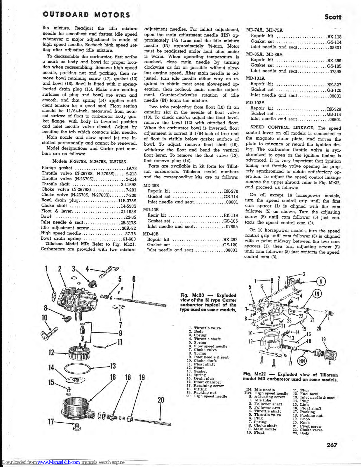
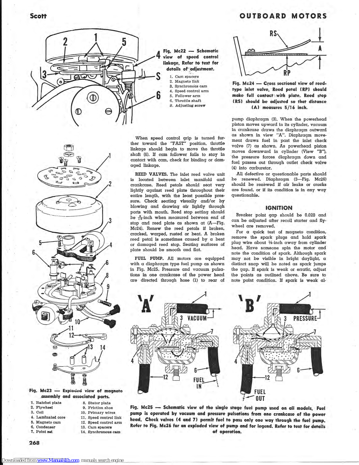
Scott 5 Hp Series, 16 Hp Series, 7.5 Hp Series, 10 Hp Series Service Data

Page 1

SCOTT

McCULLOCH CORPORATION 6101 West Century Blvd. Los Angeles 45, California

CONDENSED SERVICE DATA

Series
Year Produced
5 Hp 7.5 Hp
Mo
10 Hp
del
16 Hp
1955 & 1956 5 Bail- 7.5 Bail- 10 Bail- 16 Bail-
1957 3775 3375 3875 3975
1959 137A 1233
133A
1238
138A
1239
TUNE-UP
Нр @ грт 5 @ 4200 7.5 @ 4200 10 @ 4200 16 @ 4200
Bore—Inches 1 11/16 2 2 11/64 2 11/32
Stroke—Inches 1 43/64 13/4 2 25/16
Displacement—Cu. In
Spark Plug
7.48 11.0 14.82 19.95
Champion HIOT H10I HIOT 5MT
Electrode Gap 0.035 0.035 0.035 0.035
Magneto 0.000 0.000
Point Gap 0.020 0.020 0.020 0.020
Timing. See Text 0.020
Carburetor 5 7 W .
Make -Carter or Tillotson Contract of the
Model See Text-
Adjustment See Text-
Fuel - Oil Ratio 16:1 16:1 16:1 16.1
SIZES-CLEARANCES
Cylinder_Digmeter 1
Piston Rings
*********
********
Crankshaft Journal Diameters
Top Main Bearing ******
Center Main Bearing
Lower Main Bearing
Crankpin
TIGHTENING TORQUES
All Values in Inch-Pounds)
Connecting Rod 70-80 70-80 70.90 120
Crankcase Halves 60-84 60-84 60-84 60.04
Crankcase to Cylinder 0001 60-84 00-04 00-64
Cylinder Head 60-84 96-144 60.94 00-84
Power Head to Lower Unit 60-80 60-80 60.90 90-144
Flywheel Nut 500 500 500 500
Spark Plug 250 250 250 500
200 200 250 250

LUBRICATION

The power head is lubricated by oil mixed with the fuel. One-half (1/2) pint of two-cycle engine oil should be mixed with each gallon of unleaded gasoline. If outboard motor oil is not available, a good grade of regular (Type MM) SAE 30 engine oil may be substituted. Regular gasoline may be used instead of unleaded gasoline, however, the anti-knock components may shorten spark plug life. Mix gasoline and oil thoroughly, using a separate container, before pouring mixture into fuel tank.

The lower unit gears and bearings are lubricated by oil contained in the gearcase.

Only EP 90 outboard gear lubricant should Carter Model N carburetors are used. Refer be used. Use a pressure oil can with rubber seal on spout, remove upper (vent) plug and lower (drain) plug from gearcase, and with motor in upright position, fill through lower plug hole until lubricant reaches level of upper (vent) plug hole. Reinstall vent plug, remove oil can, then reinstall lower plug. Tighten both plugs securely, using new gaskets if necessary, to ensure a water-tight seal. Lubricant should be maintained at level of vent plug and drained and renewed at least once a year.

FUEL SYSTEM

to the appropriate following paragraphs for service and adjustment procedures.

Carter Model N: Refer to Fig. Mc20. Carburetors are provided with two mixture adjustment needles. The idle mixture needle (6) and high speed adjustment needle (20) mately 3/4-turn open, then readjusted under load for best performance after motor is warm. When engine is at normal operating temperature and under load, high speed needle should be adjusted to leanest position which will allow satisfactory accelera-CARBURETOR. Tillotson Model MD and tion. Clockwise rotation of the needle leans

266

Page 2

the mixture. Readjust the idle mixture needle for smoothest and fastest idle speed whenever a major adjustment is made of high speed needle. Recheck high speed setting after adjusting idle mixture.

To disassemble the carburetor, first scribe a mark on body and bowl for proper location when reassembling. Remove high speed needle, packing nut and packing, then remove bowl retaining screw (17), gasket (13) and bowl (16). Bowl is fitted with a springloaded drain plug (15). Make sure sealing surfaces of plug and bowl are even and smooth, and that spring (14) applies sufficient tension for a good seal. Float setting should be 11/64-inch, measured from nearest surface of float to carburetor body gasket flange, with body in inverted position and inlet needle valve closed. Adjust by bending the tab which contacts inlet needle. Main nozzle and slow speed jet are installed permanently and cannot be renewed. Model designations and Carter part num-

bers are as follows:

Models N-2678S, N-2679S, N-2763S

Flange gasket
Throttle valve (N-2678S, N-2763S)2-213
Throttle valve (N-2679S)2-214
Throttle shaft
Choke valve (N-2679S)7-201
Choke valve (N-2678S, N-2763S)7-230
Bowl drain plug11B-375S
Choke shaft14-590S
Float & lever
Bowl
Inlet needle & seat
Idle adjustment screw
High speed needle
Bowl drain spring
Tillotson Model MD: Refer to Fig. Mc21.

Carburetors are provided with two mixture

Manualslib.com manuals search engin

adjustment needles. For initial adjustment, open the main adjustment needle (HN) approximately 1½ turns and the idle mixture needle (IN) approximately ¾-turn. Motor must be readjusted under load after motor is warm. When operating temperature is reached, close main needle by turning clockwise as far as possible without slowing engine speed. After main needle is adjusted, turn idle needle either way as required to obtain most even slow-speed operation, then recheck main needle adjustment. Counter-clockwise rotation of idle needle (IN) leans the mixture.

Two tabs projecting from float (10) fit an annular slot in the needle of float valve (13). To check and/or adjust the float level, remove the bowl (12) with attached float. When the carburetor bowl is inverted, float adjustment is correct if 1/64-inch of free end of float is visible below gasket surface of bowl. To adjust, remove float shaft (16), withdraw the float and bend the vertical float lever. To remove the float valve (13), first remove plug (14).

Parts are available in kit form for Tillotson carburetors. Tillotson model numbers and the corresponding kits are as follows:

MD-36B
Repai r kit ł à 2 ŝ i. RK-2 70
Gaske et set ÷ i.
.,
GS-1 14
Inlet : nee edle α nd - se αt • • ÷ .086 01
M D-43B
Reair ki t
Ľ. RK-1 19
near kit .
Gasket set
GS-105
Inlet needl e and seat.
07895
1D-48B
Repair kit 5 ļ, ų 1 1 h ļ .RK-292
Gasket set , , ,
GS-120
Inlet ne edle c II 10 ł 5 56 ЭС 1 ŧ. i. 5 ŝ ž 1 ć 5 ł 08601
MD-74A, MD-75A ·
Repair kit RK-118
Gasket set GS-114
Inlet needle and seat
MD-85A, MD-86A
Repair kit RK-299
Gasket set GS-105
Inlet needle and seat
MD-101A
Repair kit RK-327
Gasket set GS-120
Inlet needle and seat
MD-102A
Repair kit RK-328
Gasket set GS-114
T 1 4

SPEED CONTROL LINKAGE. The speed control lever on all models is connected to the magneto stator plate, and moves the plate to advance or retard the ignition timing. The carburetor throttle valve is synchronized to open as the ignition timing is advanced. It is very important that ignition timing and throttle valve opening be properly synchronized to obtain satisfactory operation. To adjust the speed control linkage remove the upper shroud, refer to Fig. Mc22, and proceed as follows:

Inlet needle and seat....................................

On all except 16 horsepower models, turn the speed control grip until the first cam spacer (1) is aligned with the cam follower (5) as shown. Turn the adjusting screw (S) until cam follower (5) just contacts the speed control cam (3).

On 16 horsepower models, turn the speed control grip until cam follower (5) is aligned with a point midway between the two cam spacers (1), then turn adjusting screw (S) until cam follower (5) just contacts the speed control cam (3).

Fig. Mc20 — Exploded view of the N type Carter carburetor typical of the type used on some models.

Spring Inlet needle & seat

Fig. Mc21 — Exploded view of Tillotson model MD carburetor used on some models.

Ν. Idle needle 11. Plug
N. High speed needle 12. Fuel howl
s. Adjusting screw 13. Inlet needle & geo
1. Idle tube 14. Plug
2. Follower shaft 15. Link
3. Follower arm 16 Float shoft
4. Throttle shaft 17. Packing
5. Throttle valve 18. Packing nut
6. Plug 19 Knob
7. Spring 20 Knob
8. Choke shaft 21 Pivot screw
9. Main nozzle 22 Choke valve
10. Float 23 Body

Scott

Page 3

When speed control grip is turned further toward the "FAST" position, throttle linkage should begin to move the throttle shaft (6). If cam follower fails to stay in contact with cam, check for binding or damaged linkage.

Magneto link

REED VALVES. The inlet reed valve unit is located between inlet manifold and crankcase. Reed petals should seat very lightly against reed plate throughout their entire length, with the least possible pressure. Check seating visually and/or by blowing and drawing air lightly through ports with mouth. Reed stop setting should be 5/16-inch when measured between end of stop and reed plate as shown at (A-Fig. Mc24). Renew the reed petals if broken, cracked, warped, rusted or bent, A broken reed petal is sometimes caused by a bent or damaged reed stop. Seating surfaces of plate should be smooth and flat.

FUEL PUMP. All motors are equipped with a diaphragm type fuel pump as shown in Fig. Mc25. Pressure and vacuum pulsations in one crankcase of the power head are directed through hose (1) to rear of

OUTBOARD MOTORS

Fig. Mc24 - Cross sectional view of reedtype inlet valve, Reed petal (RP) should make full contact with plate. Reed stop (RS) should be adjusted so that distance (A) measures 5/16 inch.

pump diaphragm (3). When the powerhead piston moves upward in its cylinder, vacuum in crankcase draws the diaphragm outward as shown in view "A". Diaphragm movement draws fuel in past the inlet check valve (7) as shown. As powerhead piston moves downward in cylinder (View "B"), the pressure forces diaphragm down and fuel passes out through outlet check valve (4) into carburetor.

All defective or questionable parts should be renewed. Diaphragm (3-Fig. Mc26) should be renewed if air leaks or cracks are found, or if its condition is in any way questionable.

IGNITION

Breaker point gap should be 0.020 and can be adjusted after recoil starter and flywheel are removed.

For a quick test of magneto condition, remove the spark plugs and hold spark plug wire about 1/2-inch away from cylinder head. Have someone spin the motor and note the condition of spark. Although spark may not be visible in bright daylight, a distinct snap will be noted as spark jumps the gap. If spark is weak or erratic, adjust the points as outlined above. Be sure to note point condition. If spark is weak al-

Fig. Mc23 — Exploded view of magneto assembly and associated parts. plate 8. Stator plate

12. Speed control arm

12-

1. Ratchet p
2. Flywheel

  • 4. Laminated core
  • 5. Magneto cam

Fig. Mc25 — Schematic view of the single stage fuel pump used on all models, Fuel pump is operated by vacuum and pressure pulsations from one crankcase of the power head. Check valves (4 and 7) permit fuel to pass only one way through the fuel pump. Refer to Fig. Mc26 for an exploded view of pump and for legend. Refer to text for details of operation.

Page 4

Fig. Mc26 — Exploded view of diaphragm type fuel pump used on all models. Refer also to Fig. Mc25.

1. Crankcase hose 7. Check valve
2. Upper body 8. Filter screen
3. Diaphragm 9. Gasket
4. Check valve 10. Filter bowl
5. Lower body 11. Clamp
6, Inlet hose 12. Outlet hose

Fig. Mc27 — Schematic view of the rubber impeller type water pump used for cooling and for the automatic bailer unit. Impeller blades flex at slow speeds as shown by solid lines. The offset housing causes water to be drawn into pump body at (1N) and forces water out (OUT) as rotor area narrows. At high speeds, blades remain curved as shown by broken lines (HS) and pump operates by centrifugal action.

though points are in good condition and properly adjusted, examine the condition of point, condenser and coil wiring, and the insulation on the magneto coils. Look for broken or worn insulation or broken wires. Also check for loose or corroded connections. Renew any parts which are damaged or in poor condition. Tighten the flywheel nut to a torque of 500 inch-pounds when reassembling.

COOLING SYSTEM

WATER PUMP. All motors are equipped with a rubber impeller water pump of the general type shown in Fig. Mc27. An identical pump is mounted directly above the cooling system pump which operates the 'Bail-A-Matic," bilge pump. Operation and service procedures of the two pumps are identical. The pumps are mounted on and driven by the lower unit driveshaft and impeller housing is offset in relation to drive shaft. At slow engine speeds, the tips of impeller blades bend to follow contour of housing as shown by solid lines. Water is drawn into impeller (IN) as area between impeller blades increases. As area decreases due to shape of housing, water is forced into outlet (OUT) passage of pump. At high engine speeds, the flexible blades remain curved as shown by broken lines (HS) and the pump operates by centrifugal action. Coolant flow is thus maintained at an approximately constant level at most

The cooling system inlet is located above and aft of the propeller. When cooling system problems are encountered, first check the water inlet for plugging or partial stoppage, then if not corrected, remove powerhead from lower unit and check the condition of the water pump, water passages, gaskets and sealing surfaces.

To disassemble the "Bail-A-Matic" and water pumps after power head is removed from lower unit, remove the shift lever (23 —Fig. Mc28) and the "Bail-A-Matic" con-

Fig. Mc28 — Upper section of lower motor housing showing cooling system pump, bailer pump and associated parts.

1. Baller cover 2. Seal 3. Impeller key 4. Impeller 5. Baller body 6. Seal 7. Seal 8. Pump cover 9. Seal 10. Impeller 11. Pump body 12. Water tube 13. Exhaust baffle 14. Pivot shaft 15. Shift link 16. Actuator 17. Shift rod 18. Housing 19. Gasket 20. Seal 21. Baller outlet 22. Cover 23. Shift lever 24. Seal

necter (21); then unbolt and remove the "Bail-A-Matic" pump cover (1). Remove impeller (4), drive pin (3), body (5) and plate (8). Disassemble cooling system pump in the same manner.

When reassembling, install impellers with side marked "TOP" toward power head. Bleeder hole in cover plate (8) should be toward starboard side of lower unit. A groove on front of cover plate (8) should also be aligned with a similar mark on bailer pump body (5). Pump bodies and impellers should be liberally coated with water pump grease during installation.

POWER HEAD

R&R AND REASSEMBLE. To overhaul the power head, clamp the motor on a stand or support and remove the starter assembly, shrouds and flywheel. Remove magneto armature plate, carburetor and inlet manifold. The rear carrying handle and powerhead adapter plate is suspended from swivel bracket and front carrying handle by two springs and a rubber mount. After removing the cap screws which secure the power head to lower unit, unhook the two springs and lift the power head and adapter plate from lower unit. Disassemble the power head as outlined in the appropriate following paragraphs:

5 Horsepower Models: Refer to Fig. Mc30. One half of the crankcase is integral with the cylinder block. Upper and lower main bearings are of the needle roller type enclosed in a cage. The center main bearing of die-cast bronze is integral with the cylinder block. To disassemble, remove the cylinder head (8), inlet manifold (1) and transfer port covers (6); then unbolt and remove the crankcase front half. Pistons, rods, crankshaft and bearings are now accessible for removal and overhaul as outlined in the appropriate following paragraphs.

When reassembling, follow the procedure outlined in the ASSEMBLY paragraph.

Page 5

Scott

7.5 Horsepower Models: Refer to Fig. Mc31. Cylinder block is separate from the split crankcase. Main bearings are all of bronze, integrally cast with the crankcase. If bearings are worn or scored, the crankcase must be renewed.

To disassemble the removed power head, first remove the cylinder head (8), inlet manifold (1), the exhaust covers (25 & 26) and the transfer port covers (6). Unbolt and remove the cylinder block (5B), by sliding it off the piston assemblies, then separate the crankcase halves.

Pistons, rods and crankshaft are now accessible for overhaul as outlined in the appropriate following paragraphs.

Assemble by following the procedures outlined in the ASSEMBLY paragraph, and reversing the disassembly procedure.

10 Horsepower Models: Refer to Fig. Mc32. One half of crankcase is integral with the cylinder block. Upper and lower main bearings are of the caged needle roller type. The bronze center main bearing is cast into crankcase halves and is not renewable. To disassemble the removed power head, remove the cylinder head (8), inlet manifold (1), exhaust covers (25 & 26) and transfer port covers (6), then unbolt and remove the crankcase front half.

Pistons, rods, crankshaft and bearings are now accessible for removal and overhaul as outlined in the appropriate following paragraphs. When reassembling, follow the procedures outlined in the ASSEMBLY paragraph.

16 Horsepower Models: Refer to Fig. Mc33. Cylinder block is separate from the split crankcase. Main bearings are all of the needle roller type; the center bearing uses a split cage and loose needle rollers. Upper and lower main bearings are of the caged roller type.

To disassemble the removed power head, remove cylinder head (28), the inlet manifold and reed plate, and exhaust covers (23 & 24). Remove the flywheel, magneto armature plate, magneto retainer (5) and the advance mechanism (3 & 6); then unbolt and remove the upper bearing retaining flange (9). Remove the capscrews retaining cylinder block (25), and withdraw cylinder block from crankcase and pistons. To clean the cylinder block, remove the transfer port covers (26). Separate the crankcase halves.

Pistons, rods, crankshaft and bearings are now accessible for removal and overhaul as outlined in the appropriate following paragraphs.

Center main bearing outer race (13) and lower bearing retainer (16) are doweled to crankcase. When reassembling, make certain dowels are properly aligned, and follow the procedure outlined in the ASSEM-BLY paragraph.

ASSEMBLY. Because of the two-cycle design, crankcase and inlet manifold must be completely sealed against both vacuum and pressure. Exhaust manifold and cylinder head must be sealed against water leakage and pressure. Mating surfaces of water intake, and exhaust areas between power head and lower unit must form a tight seal.

Fig. Mc30 — Exploded view of power head used on 5 horsepower models

Inlet manifold Reed plate Oil hose Oil seal Cylinder assembly

Bracket Cylinder head Oil seal Bearing heusing

Upper main bearing Seal Piston rings Locating pin Flston pin

Connecting rod Crankshaft Lower bearing Bearing housing

. Bearing housing . Needle roller . Bleeder valve

Fig. Mc31 — Exploded view of power head assembly used on 7.5 horsepower models.

1. Inlet manifold
2. Reed plate
3. Cylinder
3. Crankcase
6. Transfer port cover
8. Cylinder head
9. Oil seal
14. Piston rings
16. Piston pin
17. Piston
18. Connecting rod
19. Crankshaft
22. Needle roller
24. Oil line
25. Exhaust cover
26. Exhaust cover
27. Cam follower

Fig. Mc32 — Exploded view of the 10 horsepower power head assembly.

t manifold 12. T
d plate 14. F
hose 15. I
nder assembly 16. E
and the second

  • 8. Cylinder head
  • 9, Oil seal
12. Upper bearing
14. Piston rings
15. Locating pin
16. Piston pin
17. Piston
18. Connecting rod
19. Crankshaft
20. Lower bearing
22. Bearing needle
23. Bleeder valve
24, Oil line
25. Exhaust cover
26. Exhaust cover

27. Cam follower

Page 6

Whenever the power head is disassembled, it is recommended that all gasket surfaces, and mating surfaces without gaskets, be carefully checked for nicks and burrs and warped surfaces which might interfere with a tight seal. The cylinder head, head end of cylinder block, and some mating surfaces of manifolds and crankcase may be checked, and lapped if necessary, to provide a smooth surface. Use a regular lapping block or a sufficiently large piece of smooth plate glass. Lay a sheet of No. 00 emery cloth on the lapping block then place the surface to be lapped on the emery cloth. Apply very light pressure and use a figure-eight motion, checking frequently to determine progress. Do not remove any more metal than is necessary. Finish lap using lapping compound or worn emery cloth. Thoroughly clean the parts with new oil on a clean, soft rag then wash with soapsuds and clean rags.

Mating surfaces of crankcase may be checked on the lapping block, and high spots or nicks removed, but surface must not be lowered. If extreme care is used, a slightly damaged crankcase may be salvaged in this manner. In case of doubt, renew the crankcase assembly.

A heavy, non-fibrous grease should be used to hold loose needle bearings in position during assembly. All other friction surfaces should be lubricated with new engine oil. Check frequently for binding of the moving parts during assembly. If binding or locking is encountered, remove the cause before proceeding with the assembly. On models with separate cylinder, assemble the crankcase, crankshaft, bearings, connecting rods and pistons, then slip the cylinder block down over pistons, using a ring compressor if necessary. Make sure rings are properly assembled with end gap surrounding the locating pins.

Gasket and sealing surfaces should be lightly and carefully coated with a gasket

cement such as Permatex No. 3. Make sure entire surface is coated, but avoid letting excess cement squeeze out into crankcase, bearings or other passages. Refer to the CONDENSED SERVICE DATA table for tightening torques.

PISTONS, PINS, RINGS AND CYLINDERS. Before detaching connecting rods from crankshaft, make certain rod and cap are properly marked for correct assembly to each other and in the correct cylinder.

Each piston is fitted with three rings which are interchangeable in grooves. Rings are pinned to prevent rotation in ring grooves as shown at (P—Fig. Mc34). NOTE: Middle ring is pinned at opposite side of piston from upper and lower rings.

Fig. Mc34 — Cross sectional view of piston showing two of the three piston ring locating pins (P). The other pin is in opposite side of piston. Rings are installed with beveled inner edge (B) to the top. Deflector (D) directs the flow of incoming fuel charge for proper scavenging.

Rings have a beveled inner edge which should be installed toward closed end of piston as shown at (B). Head end of piston is provided with a deflector (D) which directs the flow of the incoming fuel charge for proper scavenging of the cylinder. The long, sloping side of the deflector should be installed to the exhaust (Port) side of cylinder block.

The full floating piston pin is a tight push fit in piston bosses and a slightly looser fit in rod. Fit is correct when piston will rock of its own weight on the rod, with no noticeable looseness. Connecting rod is marked "TOP" for proper assembly. All bearing and friction surfaces should be lubricated during assembly.

CONNECTING ROD, CRANKSHAFT AND BEARINGS. Before detaching connecting rod from crankshaft, make certain that rod and cap are properly marked for correct assembly to each other and in the proper cylinder.

On all except the 16 horsepower models, the connecting rod is provided with 24 individual uncaged needle roller bearings at crankshaft end of rod. Connecting rods on 16 horsepower models have two rows of loose needle bearings in each rod, with a total of 56 rollers per bearing. If surface of rod and cap which forms outer race for needle bearings is rough, scored, worn or badly heat discolored, renew the connecting rod. Inspect crankpin, and if scored, out of round, or worn, renew the crankshaft. The side of connecting rod marked "TOP" should face flywheel end of crankshaft, Parting faces of rod and cap are not machined, but are fractured at point of arrows, Fig. Mc35, to provide positive location. Rod cap should be shifted back and forth a slight amount while tightening, until fractured sections of joint are in perfect mesh. When tightened completely, the parting line of rod and cap is practically invisible.

Inspect crankshaft crankpin and main bearing journal surfaces and if rough,

Fig. Mc33 - Exploded view of power head used on 16 horsepower models.

Oil line Crankcase hal Advance pinion Retainer Mounting plate Advance gear

Opper bearing Mounting plate "O" ring Connecting rod Bearing needle Bearing race Bearing race

Crankshaft Bearing housing Lower bearing Boot Grankcase half Piston pin Piston

Piston rings Exhaust cover Gylinder Transfer port cover Head gasket Winder head

Fig. Mc35 — Uneven fractured parting line of rod and cap (shown by arrows) assures positive fit after assembly. Be sure correlation marks (C) are aligned.

Page 7

Scott

scored, worn, out-of-round, or show evidence of overheating, renew the crankshaft. Renew main bearings if needle rollers are worn or pitted, or if crankshaft must be renewed because of a damaged main bearing. On models or locations without antifriction main bearings, examine the bushing surfaces for wear or damage, and renew the crankcase if indicated. All friction surfaces should be lubricated during assembly.

MANUAL STARTER

Fig. Mc36 shows an exploded view of the recoil starter assembly. To renew the starter pawls (8) or friction spring (9), remove and invert the assembled starter on a bench. Remove friction spring (9) with snap-ring pliers and withdraw the pawls.

Pulley (7) can be removed after removing friction spring (9). Be careful that recoil spring (5) remains in cavity of housing (4) when pulley is removed. If spring is to be removed, clamp spring to prevent uncoiling, using a pair of vise grip pliers. Replacement spring is coiled and secured with a band clip. Leave clip in place until spring is installed in housing. When reassembling, make sure there is sufficient tension on recoil spring to completely rewind starter rope.

LOWER UNIT

PROPELLER AND DRIVE PIN. Shear pin protection is carefully engineered for each unit. Protection depends on shear pin material as well as size. Although, in an emergency, the shear pin may be replaced by one of any available material, the correct shear pin should be installed as soon as possible to insure maximum performance and protection. All motors except 16 horsepower use a 5/32 x 7/8, brass shear pin, manufacturers part number 462-3122. The 16 horsepower motor uses a 7 x 7/8 brass

issembly,
1. Handle 5. Recoil spring
2. Panel 6. Washer
3. Roll pin 7. Pulley
4. Housing 8. Pawl
IS. Shim 9. Friction spring

Fig. Mc37 - Exploded view of gegregse housing and associated parts.

parts.

Page 8

pin, manufacturers part number 3965-3122. A spare supply of shear pins should be kept on hand. Factory equipment propeller sizes are as follows:

Propeller
Motor Diameter Pitch
5 hp ., 71/2 In. 6 In.
7.5 hp 8 In. 7 In.
10 hp (before 1958) 81/8 In. 91/2 In.
10 hp (after 1957) 7% In. 91/2 In.
16 hp 9 In. 10 In.

R&R AND OVERHAUL. Most service on the lower unit can be performed by detaching the gearcase housing from driveshaft and exhaust housing. When servicing the lower unit, pay particular attention to water pump and water tubes with respect to air or water leaks. Leaky connections may interfere with proper cooling and performance of motor.

Use Figs. Mc37 and Mc38 as a guide when overhauling the lower unit. To renew or service the propeller shaft, gear or bearings, first drain the lubricant and remove the propeller and shear pin. Remove the cap screws retaining housing (49) and remove the housing. On 16 horsepower models, housing extends into body (58). On these models, remove housing by turning and tapping with a soft hammer, and not by prying on gasket surfaces. The 16 horsepower model contains two bearings (54), and gear (57) is secured to shaft by Woodruff key and shaft nut.

To service the drive shaft, shift mechanism or forward or reverse gears, first remove the water pump and baler pump as outlined in previous COOLING SYSTEM section, drain the lower unit and clamp unit in a vise in upright position. Loosen the set screw in reverse lock actuator (28 —Fig. Mc38) and, while counting the turns, unscrew and slip out the shift rod (17). After shift rod has been removed, lower unit gear housing (Fig. Mc37) can be unbolted, removed and disassembled.

Fig. Mc40 — Exploded view of stern bracket and associated parts.

τ, KHOD
2. Stern bracket
3. Spring

4. Plunger 8. Reverse lock pin 5. Swivel bracket 9. Tilt pin 6. Locknut 10. Tilt stop 7. Washer 9.

When reassembling, screw shift rod (17) into shifter fork the same number of turns as before disassembly, then adjust the shift mechanism as outlined in the following paragraph.

ADJUSTMENT. To adjust the gear shift linkage, proceed as follows: With power head removed from lower unit, move shift lever into forward position. While holding the drive shaft, check and note the amount

of backlash in the propeller shaft. Move shift lever to reverse position and again check backlash. The amount of backlash should be EXACTLY the same in forward and reverse. If it is not, loosen the set screw in reverse lock actuator (28—Fig. Mc38), remove pin from top of shift rod (17) and screw shift rod in or out of shift fork. Turning shift rod clockwise (viewed from top) increases backlash in forward gear.

Scott

Loading...