


Copy No.:
Instruction Manual
Model No. : Scott 10,000.................
Year of Manufacture : 2004.......
Manufactured by :..........
Document Number : C9999--2........
Issue : 1.....................
Date of Issue : August 2004..............

ISSUE NOTE
This is Issue 1; Date of Issue: August 2004
Copyright 2004

Table of Contents
III
C9999--2 Issue 1
TABLE OF CONTENTS
1 INTRODUCTION & SAFETY 1--1...........................................................
1.1 Introduction 1--3....................................................................
1.1.1 Scott 10,000 Machine Specifications and Utility Requirements 1--5......................
1.2 General Safety Guidelines 1--6.......................................................
1.3 Safety Features 1--7.................................................................
1.3.1 Emergency Stop 1--7.............................................................
1.3.2 Stop and Safe 1--7...............................................................
1.3.3 Main Power Switch 1--8...........................................................
1.3.4 Guards and Covers 1--8...........................................................
1.3.5 Safety Switches 1--8..............................................................
1.4 Warnings, Cautions & Notes 1--9.....................................................
1.4.1 Warnings 1--9....................................................................
1.4.2 Cautions 1--9....................................................................
1.4.3 Notes 1--9.......................................................................
1.5 On Machine Warnings 1--10...........................................................
1.5.1 Heat Hazards 1--10................................................................
1.5.2 Electrical Shock Hazards 1--10......................................................
1.6 Safety Procedures 1--11..............................................................
1.6.1 Safety Devices 1--11...............................................................
1.6.2 Appropriate Dress 1--11............................................................
1.6.3 Keep Area Clean 1--11.............................................................
1.6.4 Grease and Oil 1--11..............................................................
1.6.5 Manual Usage 1--11...............................................................
2 INSTALLATION 2--1......................................................................
2.1 Installation Requirements 2--3........................................................
2.2 Pre-Installation Requirements 2--4....................................................
2.3 Uncrating & Placement 2--5..........................................................
2.3.1 Crate 1 -- Main Machine 2--5.......................................................
2.3.2 Crate 2 -- Additional Assemblies 2--6................................................
2.3.3 Install Tab Cutter Unit 2--6.........................................................
2.3.4 Leveling the Machine 2--8.........................................................
2.3.5 Continue Assembling Machine 2--10.................................................
2.3.6 Install Cross Conveyor 2--15........................................................
2.3.7 Install Steel Balls 2--16.............................................................
2.3.8 Connect Vacuum Canister 2--17.....................................................
2.3.9 Install Vacuum Valve 2--17..........................................................
2.3.10 Install Paper Supports on Pile Feeder 2--18...........................................
2.4 Utility Connections 2--22..............................................................
2.4.1 Electrical Connections 2--22........................................................

Table of Contents
IV
C9999--2 Issue 1
3 OPERATION 3--1.........................................................................
3.1 GENERAL INFORMATION 3--3........................................................
3.1.1 Before Operating the Machine 3--3.................................................
3.2 Operating Controls and Indicators Descriptions 3--4...................................
3.2.1 Operator’s Control Panel Layout 3--4................................................
3.2.2 Machine Stopping Device 3--4.....................................................
3.2.3 Main Operator’s Panel Control Descriptions 3--5......................................
3.2.4 Telemecanique PLC Control 3--10...................................................
3.3 Preliminary Inspection and Start-Up Procedure 3--11....................................
3.3.1 Preliminary Set-Up 3--11...........................................................
3.3.2 Pile Feeder 3--13..................................................................
3.3.3 Adjusting the Reregister Unit 3--20...................................................
3.3.4 Machine Start--Up 3--23............................................................
3.3.5 Start-Up for Run 3--35.............................................................
3.4 Handwheel and Tab Set-Up 3-37..........................................................
3.4.1 Hand Wheel and Tab Set-Up Definitions 3-38.........................................
HANDWHEEL SET-UPS FOR 5” SHEET WITH 3/16” MARGINS 3-40...............................
HANDWHEEL SET-UPS FOR 6” SHEET WITH 3/16” MARGINS 3-41...............................
HANDWHEEL SET-UPS FOR 7-1/4” SHEET WITH 3/16” MARGINS 3-42...........................
HANDWHEEL SET-UPS FOR 7-1/4” SHEET WITH 1/4” MARGINS 3-43.............................
HANDWHEEL SET-UPS FOR 7-3/4” SHEET WITH 3/16” MARGINS 3-44...........................
HANDWHEEL SET-UPS FOR 7-3/4” SHEET WITH 1/4” MARGINS 3-45.............................
HANDWHEEL SET-UPS FOR 8” SHEET WITH 3/16” MARGINS 3-46...............................
HANDWHEEL SET-UPS FOR 8-1/2” SHEET WITH 3/16” MARGINS 3-47...........................
HANDWHEEL SET-UPS FOR 8-1/2” SHEET WITH 1/4” MARGINS 3-48.............................
HANDWHEEL SET-UPS FOR 8-1/2” SHEET WITH 1/2” MARGINS 3-49.............................
HANDWHEEL SET-UPS FOR 9” SHEET WITH 3/16” MARGINS 3-50...............................
HANDWHEEL SET-UPS FOR 9-1/2” SHEET WITH 3/16” MARGINS 3-51...........................
HANDWHEEL SET-UPS FOR 9-1/2” SHEET WITH 1/4” MARGINS 3-52.............................
HANDWHEEL SET-UPS FOR 9-1/2” SHEET WITH 1/2” MARGINS 3-53.............................
HANDWHEEL SET-UPS FOR 11” SHEET WITH 1/8” MARGINS 3-54...............................
HANDWHEEL SET-UPS FOR 11” SHEET WITH 3/16” MARGINS 3-55..............................
HANDWHEEL SET-UPS FOR 11” SHEET WITH 1/4” MARGINS 3-56...............................
HANDWHEEL SET-UPS FOR 11” SHEET WITH 1/2” MARGINS 3-57...............................
HANDWHEEL SET-UPS FOR 12” SHEET WITH 3/16” MARGINS 3-58..............................
HANDWHEEL SET-UPS FOR 12” SHEET WITH 1/4” MARGINS 3-59...............................
HANDWHEEL SET-UPS FOR 12” SHEET WITH 1/2” MARGINS 3-60...............................
HANDWHEEL SET-UPS FOR 14” SHEET WITH 3/16” MARGINS 3-61..............................
HANDWHEEL SET-UPS FOR 14” SHEET WITH 1/4” MARGINS 3-62...............................
HANDWHEEL SET-UPS FOR 14” SHEET WITH 1/2” MARGINS 3-63...............................
METRIC HANDWHEEL SET-UPS FOR A4 (297mm x 210mm) TAB SIDE: 297 MM MARGIN: 0 MM 3-64
METRIC HANDWHEEL SET-UPS FOR A4 (297mm x 210mm) TAB SIDE: 210 MM MARGIN: 0 MM 3-65
METRIC HANDWHEEL SET-UPS FOR A4 (297mm x 210mm) TAB SIDE: 297 MM MARGIN: 1 MM 3-66
METRIC HANDWHEEL SET-UPS FOR A4 (297mm x 210mm) TAB SIDE: 210 MM MARGIN: 1 MM 3-67
4 MAINTENANCE 4--1......................................................................
4.1 Maintenance 4--3....................................................................
4.1.1 Machine Lubrication 4--3..........................................................
4.1.2 Chain Lubrication 4--4............................................................

Table of Contents
V
C9999--2 Issue 1
4.1.3 Vacuum Pump Maintenance 4--8...................................................
4.2 Machine Timing 4--10.................................................................
4.2.1 Maintenance Mode 4--11...........................................................
4.2.2 Preparation for Timing Procedures 4--12..............................................
4.2.3 ChainA&BRemoval 4--14.........................................................
4.2.4 Feeder Timing 4--15...............................................................
4.2.5 Plastic Feed & Cut Operating Arm 4--16..............................................
4.2.6 Tab Cutter Timing 4--17............................................................
4.2.7 Machine Cycle Cam Timing 4--18....................................................
4.2.8 Position of Kick Back Cam 4--19.....................................................
4.2.9 Reregister Section 4--20............................................................
4.2.10 Rubber Kick Back Roller 4--21......................................................
4.2.11 Tab Cutting 4--22..................................................................
4.2.12 Reinstall Chains 4--23..............................................................
4.2.13 Calibration 4--24..................................................................
4.2.14 Handwheel Settings 4--25..........................................................
4.2.15 Handwheel Calibration Procedures 4--26.............................................
4.2.16 Plastic Size Handwheel 4--27.......................................................
4.2.17 Plastic Position Handwheel 4--29....................................................
4.2.18 Tab Position Handwheel 4--31.......................................................
4.2.19 Tab Position Calibration 4--33.......................................................
4.2.20 Slip Rings and Brushes 4--35.......................................................
4.2.21 Plastic Feed and Fold Mechanism 4--36..............................................
4.2.22 Chip Removal System 4--40........................................................
4.2.23 Tip Die Assembly 4--41............................................................
4.2.24 Reinstalling the Tip Die Assembly 4--44..............................................
4.2.25 Hold Down Strap on Delivery Conveyor 4--45.........................................
4.2.26 Setting Tab Cutter Knives 4--46......................................................
4.2.27 Paper Stocks 4--50................................................................
4.2.28 Hot Roller 4--52...................................................................
4.2.29 Plastic Reel Holder Adjustment Procedure 4--54.......................................
4.2.30 Fiber Optics 4--55.................................................................
4.2.31 Machine Cleaning 4--58............................................................
4.2.32 Feed, Drive, Hold Down & Tension Rollers 4--58.......................................
5 SCOTT 10,000 PARTS 5-1................................................................
5.1 ASSEMBLY LOCATOR 5-4...............................................................
5.2 PILE FEED - REGISTER BOARD ADJUSTMENT 5-6........................................
5.3 PILE FEED DRIVE 5-8...................................................................
5.4 PILE FEED DRIVE & TENSIONER 5-10.....................................................
5.5 PILE FEED - VACUUM BAR DRIVE 5-12....................................................
5.6 PILE FEED - VACUUM BAR 5-14..........................................................
5.7 PILE FEED - PAPER GUIDE 5-16..........................................................
5.8 PILE FEED - OPTIC MOUNTING 5-18
......................................................
5.9 PILE HEIGHT ASSEMBL Y 5-20............................................................
5.10 PILE LIFT DRIVE 5-22...................................................................
5.11 PILE LIFT FRAME 5-24..................................................................
5.12 PILE LIFT HANDWHEEL 5-26............................................................
5.13 PILE FEED - SHEET SEPARATOR 5-28...................................................
5.14 PILE FEED -- STACK GUIDE 5-30.........................................................

Table of Contents
VI
C9999--2 Issue 1
5.15 PILE FEED - PNEUMATIC FITTINGS 5-32.................................................
5.16 PILE FEED - GUARDS, COVERS 5-34....................................................
5.17 PILE FEED - OPTIC MOUNTING 5-36.....................................................
5.18 PILE FEED - PNEUMATIC CONTROLS “A” 5-38............................................
5.19 PILE FEED - PNEUMATIC CONTROLS “B” 5-40............................................
5.20 PILE FEED - BELT & CHAIN LAYOUT 5-42.................................................
5.21 MAIN MOTOR & VACUUM PUMP 5-44....................................................
5.22 BASE & DRIVE 5-46....................................................................
5.23 BASE & DRIVE 5-48....................................................................
5.24 BASE & DRIVE 5-50....................................................................
5.25 MACHINE GUARDS 5-52................................................................
5.26 CHAIN ASSEMBLY & PG. 8 REF. 5-54.....................................................
5.27 REGISTER BOARD - HOLD DOWN PLATE 5-56............................................
5.28 REGISTER BOARD - CONVEYOR 5-58...................................................
5.29 PLASTIC CUT - BASE 5-60..............................................................
5.30 PLASTIC CUT ASSEMBLY 5-62..........................................................
5.31 TIP DIE UNIT 5-64......................................................................
5.32 PLASTIC FEED UNIT ASSEMBLY (A) 5-66.................................................
5.33 PLASTIC FEED UNIT ASSEMBLY (B) 5-68.................................................
5.34 PLASTIC FEED ASSEMBL Y (C) 5-70......................................................
5.35 PLASTIC FEED UNIT - ROLLERS 5-72....................................................
5.36 PLASTIC FEED - SLIDE 5-74.............................................................
5.37 PLASTIC FEED - DRIVE 5-76............................................................
5.38 PLASTIC FEED UNIT - COVERS & GUARDS 5-78..........................................
5.39 PLASTIC REEL HOLDER 5-80...........................................................
5.40 CONTROL PANEL 5-82..................................................................
5.41 HEAT ROLLER SHAFTS 5-84............................................................
5.42 HEAT ROLLER -- BEARING BLOCKS 5-86.................................................
5.43 PAPER SUPPORT PLATE -- TAB WIPER 5-88..............................................
5.44 HEAT ROLLER -- GEARS & SPROCKETS 5-90.............................................
5.45 Slip Ring Assembly 5-92.................................................................
5.46 Heat Roller -- Slip Rings & Brush Blocks 5-94...............................................
5.47 TAB WIPER UNIT 5-96..................................................................
5.48 TAB WIPER -- HOLD DOWN ROLLER 5-98................................................
5.49 HEAT ROLLER -- GUARDS 5-100..........................................................
5.50 REREGISTER UNIT -- REAR FRAME 5-102.................................................
5.51 REREGISTER UNIT -- LINKAGE 5-104.....................................................
5.52 TABCUTTER GUARD 5-106...............................................................
5.53 HOLDDOWN UNIT 5-108.................................................................
5.54 REREGISTER DRIVE 5-110...............................................................
5.55 KICK BACK UNIT 5-112..................................................................
5.56 KICK BACK UNIT 5-114
..................................................................
5.57 GEARBOX & REREGISTER SLIDE ASS’Y 5-116.............................................
5.58 CONVEYOR UNIT 5-118..................................................................
5.59 CONVEYOR UNIT 5-120..................................................................
5.60 PULL BACK UNIT 5-122..................................................................
5.61 PULL BACK UNIT 5-124..................................................................
5.62 PULL BACK UNIT 5-126..................................................................
5.63 REREGISTER DRIVE 5-128...............................................................
5.64 REREGISTER DRIVE 5-130...............................................................
5.65 REREGISTER UNIT -- VIEW -- A (PREV. PG’S.) 5-132........................................

Table of Contents
VII
C9999--2 Issue 1
5.66 REREGISTER UNIT -- VIEW -- B (PREV. PG’S.) 5-134........................................
5.67 INFEED UNIT 5-136......................................................................
5.68 TAPE SUPPORT PLATES 5-138...........................................................
5.69 TAB CUTTER - KNIFE CARRIER (L.H.) 5-140...............................................
5.70 TAB CUTTER - KNIFE CARRIER (R.H.) 5-142...............................................
5.71 TAB CUTTER 5-144......................................................................
5.72 TAB CUTTER 5-146......................................................................
5.73 TAB CUTTER DRIVE LINKAGE 5-148......................................................
5.74 HANDWHEEL UNIT -- REREGISTER/ TAB CUTTER 5-150....................................
5.75 HANDWHEEL UNIT -- PLASTIC POSITION 5-152............................................
5.76 HANDWHEEL UNIT -- PLASTIC SIZE 5-154.................................................
5.77 HANDWHEEL LOCAT OR 5-156............................................................
6 ELECTRICAL PAG E 6-1

1 Introduction & Safety
1--1
C9999--2 Issue 1
1 INTRODUCTION & SAFETY
C9999--2 Issue 1

1 Introduction & Safety
1--2
C9999--2 Issue 1

1 Introduction & Safety
1--3
C9999--2 Issue 1
1.1 Introduction
The Scott 10,000t uses a vacuum feeder for accuracy with many stocks, heated bonding rollers, tab
cutting knives and cross conveyor for hands--off operation.
Tab sizes range from 1/2 inch to 5 inches (12.7 mm to 127 mm) by simply rotating the Tab Size handwheel.
The extra long tool steel knives quickly and easily cut a one inch (25.4 mm) tab in the first position on a 14
inch (355.6 mm) long sheet.
CROSS
CONVEYOR
OPERATORS
PAN EL
PILE
FEEDER
TIP DIE
ELECTRICAL
BOX
PLASTIC SIZE
HANDWHEEL
PAPER LIFT
HANDWHEEL
PLASTIC
POSITION
HANDWHEEL
TAB
CUTTER
PULL BACK
ASSEMBLY
Fig. 1-1. Machine Front View

1 Introduction & Safety
1--4
C9999--2 Issue 1
TAB CUTTER
ASSEMBLY
TAB
SIZE
HANDWHEEL
TAB POSITION
HANDWHEEL
CROSS
CONVEYOR
REREGISTER UNIT
(UNDER CROSS
CONVEYOR)
Fig. 1-2. Reregister / Cross Conveyor
FILM
GUIDES
VACUUM
UNIT
MAIN POWER
INLET
REEL HOLDER
DRIVE
MOTOR
AREA
PLASTIC CHIP
VACUUM
PLUG
TRANSFORMER
Fig. 1-3. Machine Back View

1 Introduction & Safety
1--5
C9999--2 Issue 1
1.1.1 Scott 10,000 Machine Specifications and Utility Requirements
Model Scott 10,000t
Speed
Up to 10,000 plastic index tabs per hour
Sheet Size
355.6 mm x 342.9 mm (14” x 13--1/2”) maximum
127 mm x 111.1 mm (5” x 4--3/8”) minimum
Plastic Size
139.7 mm (5--1/2”) maximum
25.4 mm (1”) minimum
Tab Cut Siz e
127 mm (5”) maximum
12.7 mm (1/2”) minimum
Paper Load
Approximately 2000 sheets
Counter
1 -- 999,999
Motor
2 Horsepower
Electrical Requirements
40 Amps, 220VAC single phase, 50 or 60 Hz
Decibel Rating
94db
Dimensions
L-- 3200 mm, (126”) includes conveyor
W-- 1219 mm (48”)
W-- 1955 mm (77”) with conveyor
H--1752 mm (69”)
Shipping Weight
Approximately 1509.55 kg (3,325 lbs)
Warranty
One year against defects in parts and workmanship. Labor Not Included.

1 Introduction & Safety
1--6
C9999--2 Issue 1
1.2 General Safety Guidelines
Providing a safe working environment for operating your machine is the responsibility of the user. The
suggested precautions, material safety data and other suggestions that follow do not have preference over
the user’s own plant practices, regulations or safety committee recommendations.
Personal injury and equipment damage can be avoided by the continued adherence to the safety features
provided with this machine and in keeping with the necessary governmental requirements. The guarding
and interlocking safety switches have been installed on the machine for the operator’s safety. These items
should be maintained in good working order by the user.
It is assumed that the user’s safety department has established a safety program that is in keeping with a
complete analysis of industrial hazards. Before installing and operating or performing maintenance and
clean--up procedures on the machine, it is suggested that the safety program be reviewed to ensure that it
covers the possible hazards that might occur with the operation of this machine.
Due consideration must be given to those hazards which arise from the presence of electrical power, high
temperature, and cleaning materials used in the operational areas of the machine. Proper installation and
care of protective devices and over--pressure protective equipment should be considered an essential part of
any safety program.
Special lock--out features are to prevent the possibility of applying power to the equipment at any time when
maintenance work is in progress.
In general, personnel should be guided by all basic rules of safety associated with the equipment and the
process. It should be further understood that information contained in this manual does not relieve operating
and maintenance personnel of the responsibility of exercising normal good judgment in operating and care of
the machine and its attendant equipment.

1 Introduction & Safety
1--7
C9999--2 Issue 1
1.3 Safety Features
EMERGENCY
STOP
RUN/SAFE/MAINT
KEYSWITCH
STOP
PUSHBUTTON
Fig. 1-4. Safety Feature Locations
E--STOP
Fig. 1-5. Know Where Emergency Stop Button
is Located
These safety features are to be used in conjunction
with the installation, operation and maintenance
instructions contained in this manual.
1.3.1 Emergency Stop
Stops machine drive immediately. This pushbutton
must be manually pulled out to reset.
STOP
RUN
SAFE
MAINT
Fig. 1-6. Know How to Stop Machine & Set Key
Switch to SAFE
1.3.2 Stop and Safe
The machine operator, clean--up and maintenance
personnel MUST be shown how to stop the
machine and place the KEY SWITCH on the
operator’s CONTROL PANEL in the SAFE mode
whenever machine is accessed or clean--up
operations are performed.

1 Introduction & Safety
1--8
C9999--2 Issue 1
Fig. 1-7. Turn Machine Off Before Making
Adjustments
1.3.3 Main Power Switch
If machine is to be shut down for adjustments or
repairs, turn the power supply to the machine off.
Fig. 1-8. Blade Hazard Warning
1.3.4 Guards and Covers
All safety guards, protective screens and covers
MUST be in place and securely fastened before
operating the machine.
Observe Danger warnings. Use extra care around
moving cutting blades.
SAFETY
SWITCH
Fig. 1-9. Safety Devices
1.3.5 Safety Switches
The covers of the machine are connected to
interlock safety devices for your protection.
Machine will stop operating if a safety cover or
guard is opened while the machine is running. The
rollers will continue to maintain unless the rear
machine roller guard is removed.
1 Introduction & Safety
1--9
C9999--2 Issue 1
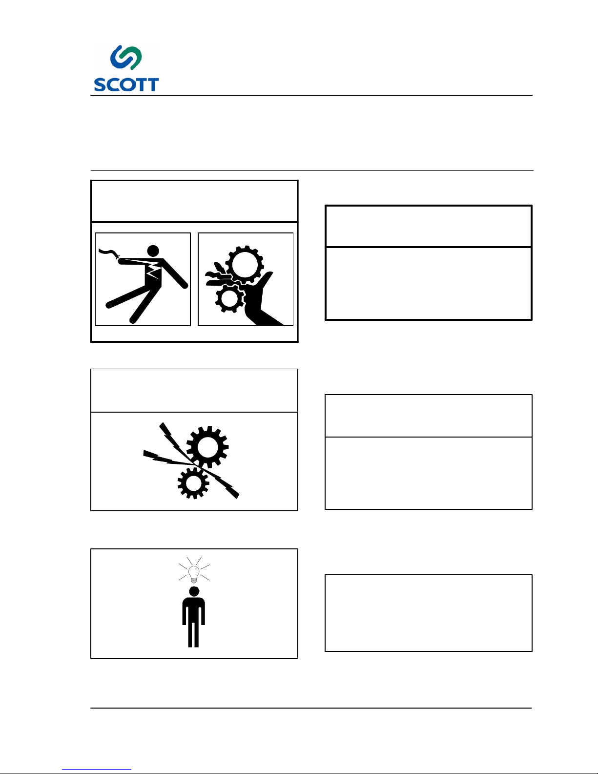
1.4 Warnings, Cautions & Notes
In order to emphasize certain areas in the interest of personal safety and a properly operated and maintained
machine, you will encounter the words WARNING, CAUTION, and NOTE throughout this manual.
WARNING!
Fig. 1-10. Warnings Indicate Personal Danger
1.4.1 Warnings
AN OPERATING PROCEDURE,
PRACTICE, ETC. WHICH IF NOT
CORRECTLY FOLLOWED, COULD
RESULT IN PERSONAL INJURY OR
LOSS OF LIFE.
WARNING!
CAUTION!
Fig. 1-11. Cautions Indicate Potential Damage
to Equipment
1.4.2 Cautions
AN OPERATING PROCEDURE,
PRACTICE, ETC. WHICH, IF NOT
STRICTLY OBSERVED, COULD RESULT
IN DAMAGE TO OR DESTRUCTION OF
EQUIPMENT.
CAUTION!
Note !
Fig. 1-12. Notes Indicate Essential Information
1.4.3 Notes
An Operating Procedure, Condition,
etc. Which is Essential To Highlight.
Note !
1 Introduction & Safety
1--10
C9999--2 Issue 1
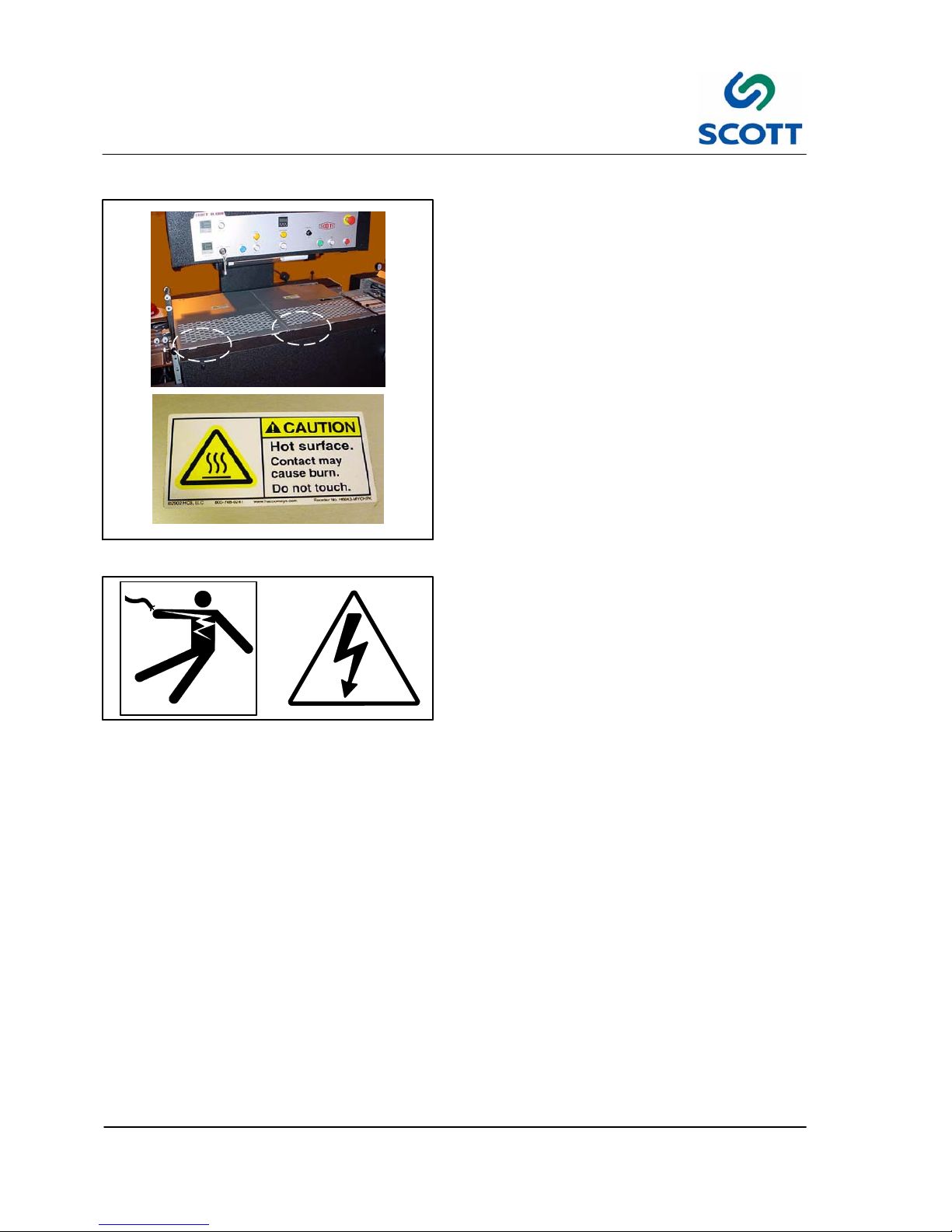
1.5 On Machine Warnings
Fig. 1-13. Heat Hazard
1.5.1 Heat Hazards
Forexample,thereisHOTSURFACEsignontop
of the Tab Wiper assembly. Look for warning signs
throughout the machine. They are there to alert
you to hazards.
Fig. 1-14. Electrical Shock Hazard
1.5.2 Electrical Shock Hazards
Look for warning signs on electrical cabinets and
circuit breaker boxes. They are there to alert you
to hazards of electrical shock.

1 Introduction & Safety
1--11
C9999--2 Issue 1
1.6 Safety Procedures
SAFETY SWITCH
Fig. 1-15. Do Not Disable Safety Devices
1.6.1 Safety Devices
Tampering with safety mechanisms in order to
disable them should not be tolerated.
IT IS EXTREMELY DANGEROUS TO ACCESS
MACHINE WHEN IT IS OPERATING OR
CAPABLE OF OPERATING.
Warning!
Fig. 1-16. Wear Proper Clothing
1.6.2 Appropriate Dress
Personnel working in the machine operation area
must remove jewelry and neckties. Personnel
must wear clothing appropriate for the work area.
Fig. 1-17. Keep Work Area Clean and Neat
1.6.3 Keep Area Clean
Loose materials, tools and equipment, not
essential to the operation of the machine, must be
removed from the machine work area.
Fig. 1-18. Clean Up Oil and Grease Spills
1.6.4 Grease and Oil
Clean up all oil and grease spills around the
machine work area.
Fig. 1-19. Read Manuals First
1.6.5 Manual Usage
Read and understand the instructions in the
manual before operating, adjusting or servicing
machine.

2 Installation
2--1
C9999--2 Issue 1
2 INSTALLATION
C9999--2 Issue 1

2 Installation
2--2
C9999--2 Issue 1
2 Installation
2--3
C9999--2 Issue 1
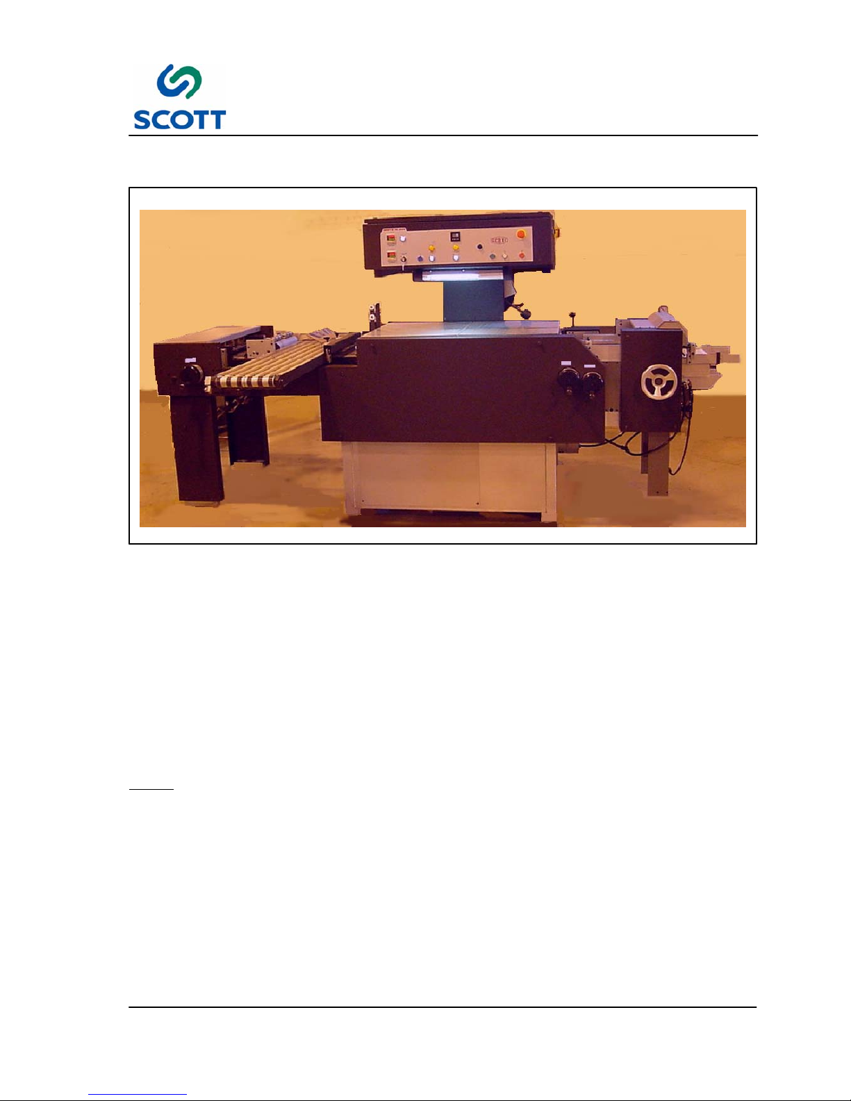
2.1 Installation Requirements
Fig. 2-1. Scott 10,000
All procedures in this section provide advance planning and site preparation data for installation of the Scott
10,000. Environmental requirements, unpacking instructions, electrical and physical specifications are
included. This information should be used as a reference during the development of site preparation plans
before you install your machine.
If any questions arise while performing any of the following procedures, contact:
Training is available from Scott Office Systems at / eight hour day, plus all travel expenses.
Note ! A forklift is required to lift the machine off the shipping skid and place it on the f loor.

2 Installation
2--4
C9999--2 Issue 1
2.2 Pre-Installation Requirements
The environmental requirements of the Scott 10,000 must be considered well in advance of the actual
installation. Providing a well suited operating environment will help ensure a trouble free installation process.
Consideration should be given to the following items:
● Power, location and rating of power connections.
● Floor strength
● Level floor
● Adequate space must be provided around all four sides of the machine to permit normal operation and
maintenance procedures. The figure shows the minimum space required.
ROLLERS
CROSS CONVEYOR
TAB CUTTER
FEEDER
15’ 9”
(4,800mm)
2’ 4”
(711mm)
3’ 2”
(965mm)
OPERAT OR
8’ 5”
(2565mm)
2’ 1”
(635mm)
6’6”
(1955mm)
Fig. 2-2. Scott 10,000 Space Requirements
● Space should be allocated near the feeder for a small table that can be used for jogging stock, small jobs,
samples, etc.
● Provide plenty of space In front of the machine so large jobs can be easily moved in and out with skids or
carts.
2 Installation
2--5
C9999--2 Issue 1
2.3 Uncrating & Placement
The machine will arrive in two crates. Inspect the external condition of the crates for visible signs of damage
before opening. If damage is noticeable, notify the carrier or Scott before proceeding with the installation.
To assist in the ease of installation, the machine is disassembled prior to shipping and requires some minor
assembly before the machine is operational.
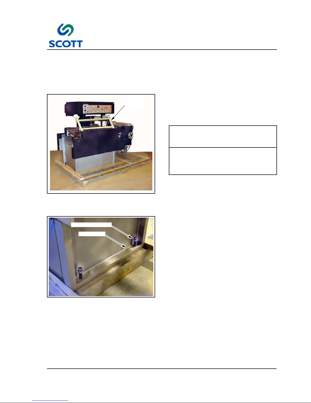
CONTROL
PAN EL
BRACE
Fig. 2-3. Scott Ten Thousand -- Crate 1
2.3.1 Crate 1 -- Main Machine
Step: 1. Remove metal banding straps from
cardboard surrounding shipping crates.
EXTREME CAUTION MUST BE
EXERCISED WHEN MOVING MACHINE
TO INSTALLATION LOCATION TO
PREVENT DAMAGE.
CAUTION!
Step: 2. Use a fork lift to place the main machine
shipping skid near the designated floor
area of operation.
LAG SCREW
LEVELING SCREWS
Fig. 2-4. Remove Lag Screws from Shipping
Skid
Step: 3. Remove four lag screws holding machine
to shipping skid.
Step: 4. Raise main machine with fork lift, remove
shipping skid assembly from under
machine.
Step: 5. Lower main machine to floor.
Step: 6. Remove all protective wrapping from
machine.
Step: 7. Remove front and rear covers and place
them aside so they won’t be damaged.
2 Installation
2--6
C9999--2 Issue 1
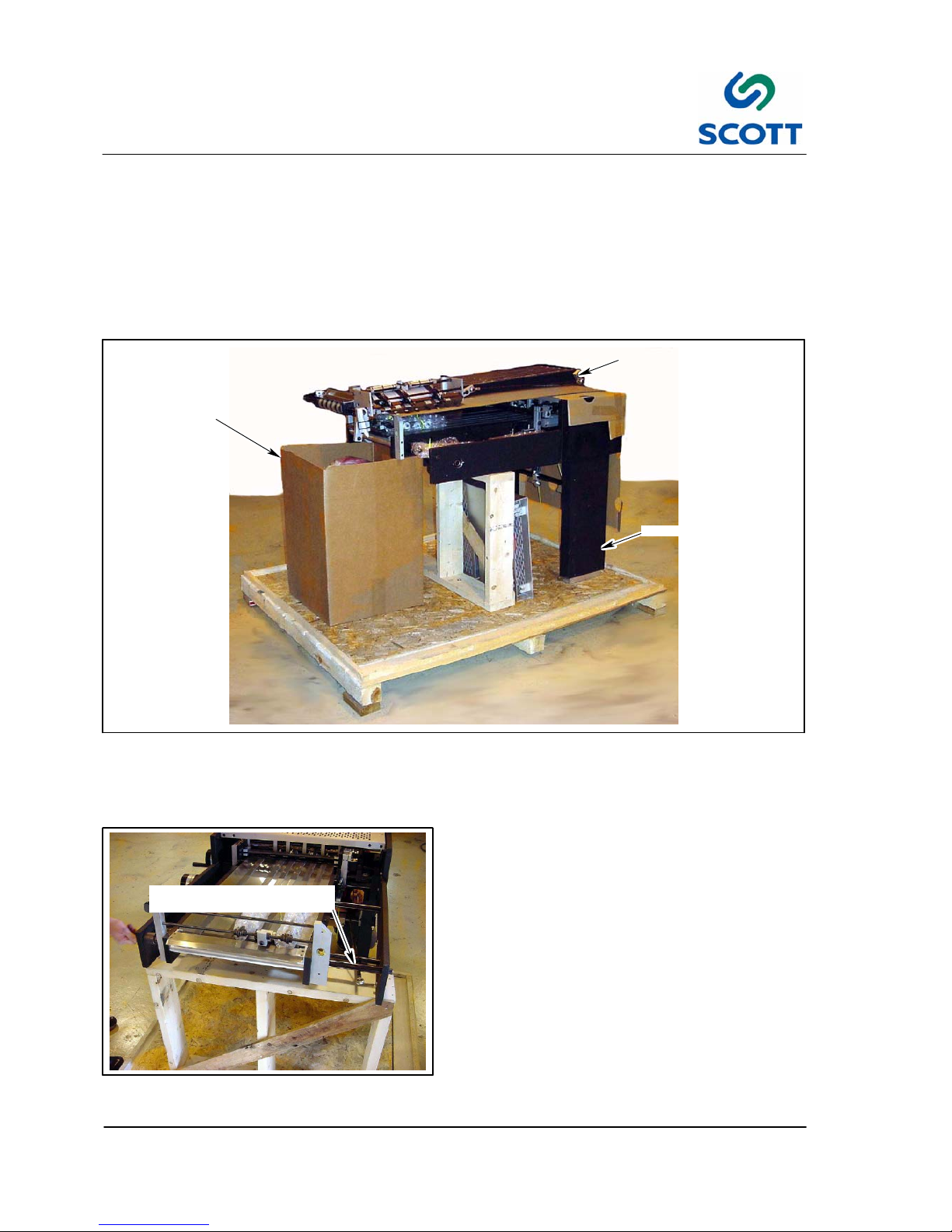
2.3.2 Crate 2 -- Additional Assemblies
Crate 2 contains all remaining equipment that was removed for shipping.
● Chip Removal Vacuum
● Tab Cutter Assembly
● Cross Conveyor Assembly
● Instruction Manual
● Miscellaneous Parts
TAB CUTTER UNIT
CROSS CONVEYOR UNIT
CHIP REMOVAL VACUUM
Fig. 2-5. Scott 10,000 on Shipping Skid (Crate 2)
Step: 1. Remove Cross Conveyor assembly from shipping skid. Place it to the side for later installation.
Step: 2. Remove vacuum unit from skid.
REREGISTER EXTENSION
MOUNTING SHAFT
Fig. 2-6. Remove Support Shaft
2.3.3 Install Tab Cutter Unit
Step: 1. Loosen hardware and slide reregister
extension frame mounting support shaft
out of tab cutter frame housing.

2 Installation
2--7
C9999--2 Issue 1
Fig. 2-7. Align Tab Cutter Assembly with Main
Machine
Step: 2. Remove Tab Cutter assembly from skid
and position it to left of the main machine
(as viewed from the front).
Step: 3. Align support shaft holes in Tab Cutter
assembly with holes in the main machine
housing.
THIS PROCEDURE REQUIRES 2--3
PERSONS.
CAUTION!
SHAFT
MAIN MACHINE FRAME
TAB CUTTER
Fig. 2-8. Reinstall Tab Cutter Shaft
Step: 4. Reinstall reregister extension frame
mounting shaft through the Tab Cutter
assembly and the gusset in the main
machine frame.
Fig. 2-9. Secure Tab Cutter Shaft
Step: 5. Secure the tab cutter shaft with socket
head screw.

2 Installation
2--8
C9999--2 Issue 1
2.3.4 Leveling the Machine
ROLLERS
CROSS CONVEYOR
TAB CUTTER
FEEDER
BACK
FRONT
RIGHT
LEFT
OPERATOR
Fig. 2-10. Locator
The machine should be on a level surface. However, if the machine is to be placed on an abnormally
uneven floor, the machine must be leveled in the following manner:
Note ! Tab Cutter/ Reregister / Conveyor section must be level with the main machine. Level the
knife section with the main machine to prevent excess wear of knives. It is important that
the knife section has the same pitch front to back as the main machine. Place a level in the
main machine across the roller keeper blocks and compare it to the knife packages. Adjust
knife package to the same bubble location on the level.
THREADED LEVELING
HOLES
(2 FRONT)
Fig. 2-11. Leveling Rod Installation (Front)
Step: 1. Install the 3/4” #10 leveling bolts through
four threaded holes in the machine
weldment.
Step: 2. The leveling bolts can be then used to
level the machine. Tighten jam nuts to
maintain level position when attained.

2 Installation
2--9
C9999--2 Issue 1
THREADED LEVELING
HOLES
(2 BACK)
Fig. 2-12. Leveling Rod Installation (Back)
Fig. 2-13. Place Level on Main Machine Frame
Step: 3. Place a level on the machined surface of
the main machine frame.
Step: 4. Adjust threaded rods in machine base to
obtain level machine side to side.
ROLLER KEEPER
BLOCKS
Fig. 2-14. Place Level Across Machine as
Shown
Step: 5. Place a level across the roller keeper
blocks.
Step: 6. Adjust threaded rods in machine base to
obtain level machine front to rear.

2 Installation
2--10
C9999--2 Issue 1
KNIFE PACKAGE
Fig. 2-15. Level Tab Cutter Assembly Side to
Side
Step: 7. Place a level on machine frame to level
Tab Cutter assembly from Side to Side.
Fig. 2-16. Level Tab Cutter Assembly Front to
Back
Step: 8. Place a level on machine frame to level
Tab Cutter assembly from Front to Back.
Fig. 2-17. Remove Packing on Hold--Down
Roller Assembly
2.3.5 Continue Assembling Machine
Step: 1. Remove packing wrap from the
Hold--Down Roller assembly.

2 Installation
2--11
C9999--2 Issue 1
HOLD--DOWN
ASSEMBLY
THUMBSCREW
SUPPORT
SHAFT
Fig. 2-18. Attach Hold--Down Assembly
Step: 2. Loosen hardware and remove register
hold--down support shaft from mounting
blocks.
Step: 3. Rotate the longer Hold--Down Roller
assembly up and reinstall support shaft
through assembly and mounting blocks.
Step: 4. Tighten mounting hardware.

2 Installation
2--12
C9999--2 Issue 1
MACHINE CYCLE CAM
TAB CUTTER DRIVE SHAFT
PILE FEED & CUT
KICK BACK CAM
Fig. 2-19. Make Sure TIming Marks Are Aligned
Note ! Before installing the Tab Cutter drive chain, it is critical that all of the timing marks shown in
Fig. 2-19. are aligned and that the heat rollers are set in the positions shown in Fig. 2-20.
Step: 5. Make sure the timing marks on Pile Feed and Cut Linkage, the Machine Cycle Cam, Tab Cutter
Drive and Kick Back Cam are aligned.

2 Installation
2--13
C9999--2 Issue 1
REGISTER
DRIVE
CHAIN
HEATER ROLLERS
REGISTER DRIVE CHAIN TENSIONER
REPRESENTS
SPROCKETS
Fig. 2-20. Heat Roller Positions (Front)
Step: 6. Make sure all heaters are aligned as shown above.
Step: 7. Install register drive chain.
1” DEFLECTION
Fig. 2-21. Tighten Chain Tension
Step: 8. Adjust register drive chain tensioner so
that there is approximately one inch (1/2”
either side of centerline) of deflection in
chain.

2 Installation
2--14
C9999--2 Issue 1
REMOVE PROTECTIVE WRAP
KNIFE
BLADES
Fig. 2-22. Remove Shipping Wrap from Knife
Blades
Step: 9. Remove shipping protective wrap from
tab cutting knives.
Fig. 2-23. Attach Tab Cutter Drive Linkage
Step: 10.Attach tab cutter drive linkage.
Fig. 2-24. Safety Wiring Harness
Step: 11.Removetiewrapfromsafetywiring
harness.

2 Installation
2--15
C9999--2 Issue 1
Fig. 2-25. Connect Safety Wiring Harness
Step: 12.Connect safety wiring harness to tab
cutter guard safety switch.
Fig. 2-26. Install Cross Conveyor Assembly
2.3.6 Install Cross Conveyor
Step: 1. Install the Cross Conveyor assembly.
ASSEMBLING THE CROSS CONVEYOR
IS A TWO PERSON TASK.
CAUTION!
CROSS CONVEYOR SHAFT
BEARING BLOCK
Fig. 2-27. Insert Cross Conveyor Shaft Into
Bearing Block
Step: 2. Insert cross conveyor drive shaft into
bearing block on the main machine.

2 Installation
2--16
C9999--2 Issue 1
MOUNTING BLOCK
Fig. 2-28. Tighten Mounting Block Screws
Step: 3. Lightly tap mounting block with a rubber
mallet to align.
Step: 4. Tighten socket head screws in cross
conveyor mounting block.
CROSS CONVEYOR LINKAGE
Fig. 2-29. Attach Cross Conveyor Linkage
Step: 5. Attach the cross conveyor linkage.
PILE FEED
HOLD--DOWN
BAR
REGISTER BOARD
HOLD DOWN PLATE
Fig. 2-30. Install Ball Bearings
2.3.7 Install Steel Balls
Step: 1. Install steel balls in the register board
hold--down plate and the pile feed
hold--down bar.

2 Installation
2--17
C9999--2 Issue 1
Fig. 2-31. Install Vacuum Canister
2.3.8 Connect Vacuum Canister
Step: 1. Once the machine is in place, assemble
the vacuum blower and canister.
CHIP REMOVAL
VACUUM OUTLET
VACUUM HOSE
HOSE CONNECTION
Fig. 2-32. Connect Vacuum Hose
Step: 2. Route the vacuum hose under the tab
cutter end of the machine and connect to
the opening under the Tip Die assembly.
Step: 3. Plug power cord for vacuum blower into
auxiliary outlet located on the back of the
machine.
VACUUM
VALV E
Fig. 2-33. Install Vacuum Valve
2.3.9 Install Vacuum Valve
Step: 1. Install vacuum adjustment valve.

2 Installation
2--18
C9999--2 Issue 1
Fig. 2-34. Pile Feed Area
2.3.10 Install Paper Supports on Pile
Feeder
For shipping purposes, the paper support
assembly is removed from the machine.
SET SCREWS
Fig. 2-35. Loosen Set Screws in Block
Step: 1. Loosen set screws in stack support bar
mounting block.
ROD
SUPPORT
Fig. 2-36. Slide Rods to Mount Paper Support
Step: 2. Slide rods toward front of machine to
create clearance for end paper support.
Step: 3. Install paper support.

2 Installation
2--19
C9999--2 Issue 1
1/4”
ROD
PAPER SUPPORT
STACK SUPPORT BAR
MOUNTING BLOCK
Fig. 2-37. Rods Should Extend 1/4” Beyond
Supports
Step: 4. The ends of the stack support bars
should extend 1/4 inch beyond paper
support.
Step: 5. Tighten the set screws in the stack
support bar mounting block.
PAP ER S U PPO RT
Fig. 2-38. Install Remaining Support Blocks
Step: 6. Install remaining paper supports on stack
support rods.
Fig. 2-39. Install RH Side Paper Stack Guide
Step: 7. Install RH paper stack guide.
Step: 8. Tighten set screws.

2 Installation
2--20
C9999--2 Issue 1
Fig. 2-40. Install LH Side Paper Stack Guide
Step: 9. Install LH paper stack guide.
Step: 10.Tighten set screws.
RH STACK GUIDE
SIDE RACK GUIDE
Fig. 2-41. Slide the RH Stack Guide Flush with
Side Rack Guide
Step: 11.Slide the RH stack guide so that it is flush
with the edge of the side rack guide.
Step: 12.Tighten set screws.
Fig. 2-42. Pile Feed With All Supports and
Guides Installed

2 Installation
2--21
C9999--2 Issue 1
Fig. 2-43. Remove Wire Ties From Air Hoses
Step: 13.Carefully remove the wire ties holding the
air hoses.
Fig. 2-44. Insert Air Hoses into Connectors
Step: 14.Insert air hoses into connectors.

2 Installation
2--22
C9999--2 Issue 1
DANGER: ELECTRICAL CONNECTIONS
MUST BE MADE BY A QUALIFIED
ELECTRICIAN FAMILIAR WITH
APPLICABLE ELECTRICAL CODES
AND REGULATIONS. ELECTRICAL
CONNECTIONS MUST THEN BE MADE
ONLY AFTER REVIEWING AND
UNDERSTANDING THE ELECTRICAL
SCHEMATICS SUPPLIED WITH
MACHINE AND SAFETY SECTION OF
THIS MANUAL, FAILURE TO EXERCISE
NECESSARY SAFETY PRECAUTIONS
CAN RESULT IN SERIOUS BODILY
INJURY OR DEATH.
WARNING!
2.4 Utility Connections
2.4.1 Electrical Connections
The machine requires No. 8, 3 wire cable including
ground for 220 volt, single phase electrical power.
Note ! Electrical cables going to machine
should be routed overhead and be of
sufficient height to allow personnel to
travel around entire machine without
interference. The figure below shows
recommended installation
configuration.
GROUND
TERMINAL
1L1
TERMINAL
5L3
TERMINAL
Fig. 2-45. Installation Wiring Route
1. Route main power electrical cable through the conduit opening in the back of the control cabinet.
2. Connect two “hot” leads onto terminals 1L1 and 5L3 on main power relay. Connect neutral lead to
ground terminal.

3 Operation
3--1
C9999--2 Issue 1
3 OPERATION
C9999--2 Issue 1

3 Operation
3--2
C9999--2 Issue 1

3 Operation
3--3
C9999--2 Issue 1
3.1 GENERAL INFORMATION
3.1.1 Before Operating the Machine
AVOID SERIOUS INJURY OR EQUIPMENT
DAMAGE. RESTRICT OPERATION OF THIS
MACHINE TO TRAINED, QUALIFIED
PERSONNEL ONLY.
WARNING!
EACH OPERATOR SHOULD KNOW THE
LOCATION AND FUNCTION OF ALL
MACHINE STOPPING CONTROLS.
REVIEW MANUAL FOR EMERGENCY
STOP BUTTON LOCATION.
WARNING!
Do not attempt to operate the machine before reading and understanding the manual. Pay close attention to
all WARNINGS, CAUTIONS and NOTES. Failure to do so may cause serious injury and extensive machine
damage.
Read through the inspection and pre--start procedures before starting the machine. Make these checks part
of your routine to insure efficiency and quality during the production run.

3 Operation
3--4
C9999--2 Issue 1
3.2 Operating Controls and Indicators Descriptions
3.2.1 Operator’s Control Panel Layout
STOP
PAP ER
FEED
RUN/SAFE/MAINT
RESET
ROLLER
HEAT
EMERGENCY
STOP
COUNTER
ON/OFF
COUNTER
DRIVE
SPEED
LOWER
HEAT
COUNT
REACHED
PLASTIC
FEED
START
OUT OF
PLASTIC
UPPER
HEAT
Fig. 3-1. Control Panel
E--STOP
Fig. 3-2. Emergency Stop Pushbutton
3.2.2 Machine Stopping Device
3.2.2.1 EMERGENCY STOP -- Red Pushbutton
Stops the machine drive immediately. The
Emergency Stop Button is on the front of the
machine. After a stop, the button must be
manually pulled out and the Reset button pushed
before cycling can resume.

3 Operation
3--5
C9999--2 Issue 1
3.2.3 Main Operator’s Panel Control Descriptions
The following is a list of each control on the operator’s panel and a description of the functions performed at
each setting.
HEATER
Fig. 3-3. Heaters Illuminated Pushbutton
3.2.3.1 ROLLER HEAT ON / OFF --
ON -- When pushed, the button illuminates,
indicating upper and lower heaters are turned ON.
OFF -- When pushed again, the heaters are turned
OFF.
Approximate warm up time for heaters is between
25--30 minutes.
RUN
SAFE
MAINT
Fig. 3-4. Run/Safe/Pendant Key Switch
3.2.3.2 SAFE / RUN / MAINT -- Key Switch
RUN -- The machine drive cycles continuously.
This is the normal switch position for production.
If conditions are safe, pushing RESET will allow
the machine to operate.
SAFE -- No machine cycle is possible.
MAINT (Maintenance) -- When the keyswitch is in
this position, the machine can only be indexed at a
slower speed. The safety doors and guards
(except for the tabcutter guard) can be removed to
perform maintenance and adjustments. If the rear
machine guard is removed, the rollers will not heat.
Always press the RESET button after changing the
switch from RUN to MAINT or visa versa.
RESET
Fig. 3-5. Reset Pushbutton
3.2.3.3 RESET -- Blue Pushbutton
Resets machine, and verifies it is safe to run after
an emergency stop.
Press this button when changing the
RUN/SAFE/MAINT switch from SAFE position to
RUN.

3 Operation
3--6
C9999--2 Issue 1
OUT OF
PLASTIC
Fig. 3-6. Out of Plastic Lamp
3.2.3.4 OUT OF PLASTIC -- LAMP
Lamp will illuminate when upon pushing the Plastic
Feed button, the proximity switch on the plastic
feed does not sense plastic at the feeder
discharge. The plastic chip removal vacuum and
the paper feed vacuum pump will also be disabled
until the plastic spool is refilled.
PLASTIC
FEED
Fig. 3-7. Plastic Feed Pushbutton
3.2.3.5 PLASTIC FEED -- White Illuminated
Pushbutton
Turns on the chip removal vacuum and allows
plastic to enter the Tip Die, if the reel is threaded
onto the machine. The plastic chip removal
vacuum operates only when Plastic Feed is on and
the machine is in Run with machine running.
COUNT
REACHED
Fig. 3-8. Count Reached Lamp
3.2.3.6 COUNTER REACHED -Amber Indicator Lamp
This lamp will illuminate when the machine has
produced the amount predetermined by the
counter. Once the count has been reached, the
paper feed vacuum pump will shut off so that paper
feed will stop. Also, if plastic is being applied to the
paper stock, the plastic chip removal vacuum will
shut off. Both units will resume operation once the
counter has been reset.
COUNTER
Fig. 3-9. Counter On/Off -- Illuminated
Pushbutton
3.2.3.7 COUNTER ON / OFF -White Illuminated Pushbutton
When the counter button is pushed, the button
illuminates indicating that the counter is on.
This will allow the operator to turn off the counter to
run make product without losing the current count.

3 Operation
3--7
C9999--2 Issue 1
START
Fig. 3-10. Start Pushbutton
3.2.3.8 START -- Green Pushbutton
Turns on main drive motor to begin machine
cycling.
This means:
● The safety switches indicate all the guards are
in place.
● The EMERGENCY STOP buttons are reset.
● The RESET button is pushed.
● The pushbutton turns on the main drive motor
for continuous machine cycling w ith the KEY
switch in RUN position only.
PAPER
FEED
Fig. 3-11. Paper Feed Pushbutton
3.2.3.9 PAPER FEED -- White Illuminated
Pushbutton
Starts the vacuum pump for the pile feeder vacuum
nozzles while the machine is cycling.
STOP
Fig. 3-12. Stop Drive Pushbutton
3.2.3.10 STOP -- Red Pushbutton
The pushbutton stops the machine drive. This is a
“soft” stop and is intended for planned stops, not
emergencies.
PLASTIC
ADVANCE
Fig. 3-13. Plastic Advance Pushbutton
3.2.3.11 PLASTIC ADVANCE -- Black
Pushbutton (Side of Machine)
It brings plastic into the Tip Die when the machine
is in Run position and cycling. It is used when
loading a new reel of film and must be held in to
move plastic to Tip Die area.

3 Operation
3--8
C9999--2 Issue 1
DRIVE SPEED
Fig. 3-14. Main Drive Feed
3.2.3.12 SPEED -- Adjustment Control
Adjusts main drive motor speed. The dial is turned
clockwise to increase, and counterclockwise to
decrease the machine drive speed.
COUNT SET
NUMBER
OF
SHEETS
RAN
COUNT SET
COUNT RESET
Fig. 3-15. Counter
3.2.3.13 COUNTER
Activating the Counter, allows operator to specify
an exact number of sheets to be run. The feeder
shuts off after the requirement has been met.
Note ! Additional sheets may be fed
depending on machine speed.
The counter only counts when the machine is in
RUN mode and the Counter button is ON. The
digital counter counts forwards to the number
specified, then shuts feeder and vacuum OFF
when that number is reached.
● Do not change setting while counter is running.
Fig. 3-16. Production Sheet Counter
3.2.3.14 PRODUCTION SHEET COUNTER
This counter will record total number of sheets.
The counter is located in the control cabinet
(CTR2).
Note ! Counter can not be reset.

3 Operation
3--9
C9999--2 Issue 1
PROCESS VALUE
SCROLL KEY
RETURN KEY
SET
VAL UE
CON:
Control
Output
ALM:
Alarm
Output
Fig. 3-17. Heater Temperature Control
3.2.3.15 Heater Temperature Control
Controls wheel heat temperature by cycling power
to the heaters. The setpoint temperature is
adjusted by using the buttons below the indicator
display.
The controller maintains process parameters when
power is off.
Touch Keys Description Function
Scroll Key Advances the index display to the desired position.
Indexes advanced continuously and cyclically by
pressing this keypad.
Up Key Increases the parameter (Set Point or Other)
Down Key Decreases the parameter (Set Point or Other)
Return Key Resets the controller to its normal status. Also stops
auto--tuning, output percentage monitoring and
manual mode operation.
Press for 6 seconds
Long Scroll Allows more parameters to be inspected or
changed.
Press for 6 seconds
Long Return 1. Executes auto--tuning function.
2. Calibrates control when in calibration level.
Press and
Output Percentage
Monitoring
Allows the set point display to indicate the control
output value in percent.
Press and
for 6 seconds
Manual Mode Execution Allows the controller to enter the manual mode.
This can be used if the sensor fails.

3 Operation
3--10
C9999--2 Issue 1
3.2.4 Telemecanique PLC Control
The Scott 10,000 incorporates two Telemecanique TSX07 Programmable Logic Controllers. Each controller
has a series of LEDs indicating the on/off status of its inputs and outputs. Separate LEDs also verify
communication between controllers. Check Electrical Sheets for a listing of the devices that are attached to
the controller and to which location (input/output), the device is attached.
When a device is active, the green LED is lit. The yellow com LED should always be lit. The second smaller
PLC will have a blinking red LED in the error position which is normal. The larger primary PLC error lamp
should not be lit.
Both PLC’s run LEDs should be solid green.

3 Operation
3--11
C9999--2 Issue 1
3.3 Preliminary Inspection and Start-Up Procedure
Fig. 3-18. Correctly Set Space Between Upper &
Lower Rollers
3.3.1 Preliminary Set-Up
3.3.1.1 Adjustment of the Space Between
Upper & Lower Bonding Rollers
It is important that the space between the upper
and lower bonding rollers is set correctly so that
the rollers grip the sheets properly but do not
actually contact each other. The rollers must not
bounce against each other as the sheets pass
through them.
If the rollers ride against each other, this will cause
the finish on the rollers to be damaged. Excessive
bouncing of the rollers will cause wear on the drive
gears and the chain drive. Bouncing will also
cause poor quality work since the rollers may not
maintain good contact with the tab just behind the
leading tab.
Step: 1. The machine must be in the Pendant
Mode when you adjust the space
between the rollers.
Fig. 3-19. Tighten Nuts to Raise Rollers
Step: 2. Raise the rollers by tightening the nuts on
the bearing blocks so as to lift the upper
rollers.

3 Operation
3--12
C9999--2 Issue 1
LOWER ROLLERS
UPPER ROLLERS
Fig. 3-20. Raise the Rollers By Tightening the
Nuts on the Bearing Blocks.
Step: 3. Insert a sheet of paper between the
rollers.
Step: 4. Lower the rollers until the paper is lightly
gripped.
Step: 5. Work back and forth between the two
rollers supported by each bearing block
until both rollers grip the paper lightly.
Step: 6. Check the rollers near the ends and
adjust between the inner and outer
bearing blocks until both ends of the
rollers grip the sheet uniformly.
Note ! The last step is important because if
the rollers and shaft are not parallel,
then many problems may occur. First,
if the gear set at the ends of the shaft
are either too tight or too loose, this
may cause the gears to wear
excessively. Second, if the rollers do
not grip the sheet all the way across,
this may cause the sheets to twist
causing quality problems.
Fig. 3-21. Reregister Roller Assembly
3.3.1.2 Adjust Reregister Roller Assembly
These units provide the grip on the sheet to drive it
in tightly against the tab cutter back stop and hold
it there while the sheet is being registered and
tabcut. Each of these units is provided with an
extension spring which is adjustable in tension by
turning the brass knob. When running the normal
range of paper stocks, this spring tension should
not require adjustment. However, when running
either lighter or heavier stocks, it may be
necessary to adjust the tension. Lighter stocks
have a tendency to buckle if the roller pressure is
too great and heavier stocks tend to bounce and
not cut uniformly.

3 Operation
3--13
C9999--2 Issue 1
Fig. 3-22. Pile Feeder Assembly
3.3.2 Pile Feeder
The paper feeder is specially designed to feed
index stocks at high speeds. It is very important
for the operator to keep the feeder in good working
condition and to learn how to adjust and correct for
various operating conditions. The importance of
this is magnified by two conditions. First, the
machine is handling papers which have already
been through two or three other machines and,
because of this, may not be in pristine condition.
Second, the stocks being fed may vary, and will
vary greatly in feeding ability. Knowing how to
make fine adjustments to compensate for various
paper conditions will greatly increase the
productivity of this machine.
VACUUM NOZZLES
Fig. 3-23. Vacuum Nozzles
The most critical area in any paper feeder is at the
point where the vacuum nozzles contact the top
sheet to lift it from the stack. If papers and
operating conditions were uniform all of the time,
this would not present a problem. However, the
papers handled by this machine tend to have
various curls, warpage, ripples, etc., which greatly
hamper feeding. The sheets may tend to curl up or
down or the entire stack may be tilted due to
moisture from printing. The following “hints” will
help the operator to keep the Scott 10,000
operating at maximum production speeds.
MOUNTING
BLOCK
SHEET
SEPARATOR
FINGER
Fig. 3-24. Adjustment to Feeder Nozzle
3.3.2.1 Sheet Separator Fingers
The position and condition of the sheet separator
fingers should be carefully maintained. Each sheet
separator finger should be centered both top and
bottom and right to left of the mounting block
opening. Care should be taken to make certain
that the fingers are free and extend into the sheet
about 1/8--inch (6.3mm). Whenever the position of
nozzles is changed, the stack guide should be
moved until the finger is slightly to the left of the
nozzle.
The separator fInger should be 1/2” (12.7mm)
above the paper stack.

3 Operation
3--14
C9999--2 Issue 1
VACUUM NOZZLE
MOUNTING
BRACKET
RETAINING RING
VACUUM
NOZZLE
MOUNTING
BRACKET
Fig. 3-25. Vacuum Nozzles Height Adjustment
3.3.2.2 Vacuum Nozzles
The machine is equipped with a floating nozzle cup
which does two things. First, it allows for slight
variations in the height of the stack and, second, it
allows the cup of the nozzle to conform to the curl
of the paper. The advantage of the floating nozzle
cup is that it will compensate for a much wider
range of operating conditions. It is important to
make certain that there is no binding condition in
the floating “cup” of the nozzle which prevents it
from dropping down on the paper each time.
The height of the vacuum nozzle is correctly set
when the retaining ring is even with the top of the
horseshoe shaped mounting bracket for the sheet
separater finger.
THUMB SCREW
MOUNTING BLOCK
VACUUM NOZZLE
PLUG
JAM NUT
Fig. 3-26. Nozzle Set Up Side to Side
Vacuum Nozzle Adjustments
Depending on size of the stock used, the vacuum
nozzles may have to be moved from one mounting
block to another.
To remove the vaccum nozzles and rubber plugs:
Step: 1. Loosen jam nuts and thumb screws.
Step: 2. Loosen the thumb screws and remove
nozzles and rubber plugs.
To Install Nozzles and Rubber Plugs:
Step: 1. Push nozzles all the way into the
mounting block and gently tighten thumb
screws and jam nuts.

3 Operation
3--15
C9999--2 Issue 1
MOUNTING SCREW
IN FEED ROLLER
FEED WINDOW
Fig. 3-27. Plastic Feed Window
3.3.2.3 Plastic Feed Window Adjustment
The plastic feed window holds the mylar in its
proper open position.
Step: 1. Loosen the in--feed roller shaft mounting
screw.
Step: 2. Rotate in--feed roller out of the way.
THUMB SCREW
Fig. 3-28. Window Assembly
Step: 3. Loosen the jam nut on the plastic thumb
screw.
Step: 4. Turn the plastic thumb screw
counter--clockwise until the window
assembly is touching the tip die and the
plastic feed tunnel.
Step: 5. Lift up the window assembly and place a
piece of the index stock (that will be used
during the production run) over the tip die
area.
Fig. 3-29. Feed Index Stock Under Window
Assembly
Step: 6. Set the window assembly down on the
index stock and slowly turn the thumb
screw clockwise until the piece of index
stock can be slide back and forth easily
without any drag or resistance.
Step: 7. Gently tighten the jam nut.

3 Operation
3--16
C9999--2 Issue 1
MOUNTING SCREW
IN FEED ROLLER
FEED WINDOW
Fig. 3-30. Adjust Feed Roller Tension
3.3.2.4 In--Feed Roller Tension Adjustment
The In--Feed Rollers are used to assist sheets into
the Heat Rollers.
To Adjust the In--Feed Rollers
Step: 1. Loosen the In--Feed roller shaft mounting
screw.
Step: 2. Use your fingers to apply downward
pressure to the spring plates and tighten
the mounting screws.
PAP ER S TOC K
STATIONARY
PAPER
GUIDES
ADJUSTABLE
PAPER
GUIDES
MIDDLE
FRONT
GUIDE
Fig. 3-31. Paper Side and Back Guides
3.3.2.5 Paper Side and Back Guides
The right hand guide remains in the same position
for all sheet sizes. The left hand guide must be
adjusted for sheet size. Allow approximately 1/16”
(1.5mm) freedom in the stack. The back guides
should be adjusted close to the stack.
3.3.2.6 Compensating for a Tilted Stack of Paper
Uneven paper stacks can be compensated for by inserting strips of binder’s board every so often on the low
side of the stack. It is recommended to use a piece of binder’s board the same size as the sheet as a
platform for the stack. Make sure it is heavy enough not to be picked up by the nozzles.
3.3.2.7 Curled Stock
The nozzles will compensate for quite a bit of curl in the paper. However, if the curl is too bad, it may be
necessary to roll the stock by hand before loading it into the pile feeder.

3 Operation
3--17
C9999--2 Issue 1
PILE HEIGHT
ADJUSTMENT
KNOB
Fig. 3-32. Pile Height Adjustment Knob
3.3.2.8 Pile Height Adjustment
During the operation of the machine, the paper
stack automatically rises until the top sheet
reaches a predetermined height. The stack height
is controlled by a checking bar above the stack.
As the stack approaches the feeding height, the
checking bar begins to strike the top of the stack.
The higher the stack, the less the bar moves and
the less the stack rises until it finally stops rising at
all. As sheets are fed into the machine, this has the
effect of lowering the top of the stack and the stack
begins to rise.
The height that the stack will rise to is controlled by
a hand knob on the outside of the R.H. feeder
cover. Lifting this hand knob will cause the stack to
rise to a higher point. Lowering the hand knob will
cause the stack to stop rising at a lower point.
During operation, the operator should lower the
hand knob to it’s bottom point; then with the
machine running and the vacuum on, gradually lift
the knob until the feeder begins to feed. The knob
should be kept at it’s lowest position possible
allowing stock to feed.
ADJUSTMENT NUT
Fig. 3-33. Vacuum System Adjustment
3.3.2.9 Vacuum System for Feeding Paper
The machine is equipped with a vacuum pump
which provides both vacuum for pick--up and blown
air for separating the sheets. The degree of
vacuum can be adjusted by adjusting the nut on
the vacuum relief valve located on the vacuum
gage.
The degree to which the vacuum is adjusted
depends on the weight and porosity of the paper
being fed. Generally speaking, the lighter and
thinner the paper, the lower the vacuum required.
The normal range of vacuum required will vary
from about 5 to 10 inches (.18 to .34 BAR) of
mercury as shown on the gage. The best practice
is to run as low as possible with continuous feeding
and with as least vacuum as possible.

3 Operation
3--18
C9999--2 Issue 1
AIR BLOW NOZZLES
Fig. 3-34. Blow --Air System
3.3.2.10 Blow-Air System
The blow-air system performs several functions.
First, it separates the sheets so the effect of the
vacuum bleeding through the paper is less critical.
Also, with the second sheet separated from the
first sheet, it allows air to get in between the sheets
when the top sheet is removed from the stack. This
prevents the first sheet from sucking up the second
sheet. Another function of the blow--air is to lift the
top few sheets until the top sheet is up against the
sheet separator finger. This establishes a uniform
height for the top sheet so that it will be in the
proper position when the nozzles come down for
the pick--up.
The feeder is equipped with four blow nozzles.
Two of these blow in from the edges of the stack
and two blow in from the front of the stack.
Fig. 3-35. Side Air Blow Nozzles
Blow air nozzle height is pre--set at the factory and
should not need to be adjusted. If they need
adjusting, the side nozzles are adjusted in height
by screwing them either up or down. The front
nozzles can be adjusted in height by first tilting
them toward the stack and then screwing them
either up or down.
To adjust direction of air nozzle, rotate nozzle to
desired location.
EXHAUST VALVE
Fig. 3-36. Adjust the Air Blow At the Exhaust
Val ve
The amount of blow--air from the nozzles can be
adjusted by use of the exhaust valve located on
the feeder guards.
The right exhaust valve controls the RH side air
blow nozzle and RH top air blow nozzle. The left
exhaust valve controls the LH side and top air
nozzles.
DO NOT RESTRICT THE BLOW AIR TO
THE POINT WHERE IT OVERLOADS
THE VACUUM PUMP. THIS CAN CAUSE
THE MOTOR TO BE DAMAGED.
CAUTION!

3 Operation
3--19
C9999--2 Issue 1
HAND
KNOB
HOLD--
DOWN
ROLLERS
Fig. 3-37. Pull-In / Hold--Down Rollers
3.3.2.11 Moving the Pull-In / Hold--Down
Rollers
The rollers can be positioned in any one of four
positions. To change, pull the hand knob up to
disengage and slide the assembly along the shaft
to the position desired.

3 Operation
3--20
C9999--2 Issue 1
3.3.3 Adjusting the Reregister Unit
Once the reregister section is adjusted for paper size, no operating adjustment should be necessary except
for dial positioning.
When the basic size of the sheet is changed, then it is necessary to adjust the unit.
Fig. 3-38. Sheet Length
3.3.3.1 Sheet Length
This is the length of the sheet from the binding side
to the edge of the tab.
The position of the delivery conveyor and the
pull--back unit should be adjusted so that the
spring gates are located approximately 1/2” in back
of the back edge (binding edge) of the sheet when
the front edge of the sheet is resting against the
tab cutter back stop in the position where it will be
tabcut. The sheet drive /holddown roller should be
tensioned as necessary using as many as
necessary to control the sheet. Adjust the sheet
catcher on the delivery conveyor so that it will
catch the sheets properly.
SHEET DRIVE /
HOLD--DOWN
ROLLER
REREGISTER
HOLDDOWN
ROLLER
Fig. 3-39. Sheet Width
3.3.3.2 Sheet Width
When the width of the sheet is changed, it may be
necessary to change one or more of the following
items:
1. Sheet Drive / Hold--Down Rollers: These
should be adjusted so that they hold the sheets
down near the outer edge. They must ride on
the feed tapes.

3 Operation
3--21
C9999--2 Issue 1
Fig. 3-40. Adjust Sheet Drive / Hold--Down
Rollers
Loosen knob and slide hold--down roller
assemblies where necessary.
MAKE CERTAIN THAT THE REAR TIP
OF THE HOLD--DOWN SHOE IS
NEITHER DOWN TOO TIGHT ON THE
LOWER TABCUTTER KNIFE SO AS TO
CAUSE THE SHEETS TO BIND OR SO
HIGH THAT THE INCOMING SHEETS
TEND TO STRIKE THE UPPER
TABCUTTER KNIVES.
CAUTION!
PAPER
HOLD--DOWN
ROLLERS
PAPER HOLD--DOWN BAR
REREGISTER BELTS
Fig. 3-41. Rollers
2. Paper Hold--Down Rollers underneath the
delivery conveyor: These rollers should be
aligned so that they on top of the register belts.
The paper hold--down bars should be between
the belts when the cross conveyor is in the
operating position (down).
HOLD--DOWN BAR ALLEN SCREW
COLLER
HOLD-- DOWN ROLLER
Fig. 3-42. Adjust Hold--Down Rollers and Bars
To adjust the hold--down roller position: Loosen the
Allen screws in the retaining collars and slide
rollers into correct position. Tighten Allen screw on
collers when roller assembly is in correct position.
To adjust the hold--down Bars: Loosen the Allen
screws in the bars and slide into position. Tighten .

3 Operation
3--22
C9999--2 Issue 1
PULLBACK HOLD--DOWN ROLLERS
Fig. 3-43. Pullback Hold--Down Rollers
3. Pullback Hold--Down Rollers: Adjust so that the
two outside units hold down near the outer
edges of the paper.
Fig. 3-44. Adjust Pullback Hold--Down Rollers
Loosen the Allen screw to move the guide
assembly. Always make sure the lower roller is on
the crown of the small pullback roller.
PULLBACK
ROLLERS
Fig. 3-45. Kick Back Rollers
4. Pull--Back Rollers: Normally no adjustment is
necessary.

3 Operation
3--23
C9999--2 Issue 1
MAIN
POWER
SWITCH
Fig. 3-46. Circuit Breaker Switch (ON)
3.3.4 Machine Start--Up
Step: 1. Main Power Switch ON.
HEATER
Fig. 3-47. Warm Up Heater
To laminate plastic to paper:
Step: 2. Press HEATER pushbutton.
Step: 3. Set temperature controllers to
220--230_F as a starting point.
Note ! Starting Heaters now will allow
heaters to reach operating
temperature while the rest of the
machine is being set up.
ADJUSTMENT KNOB
Fig. 3-48. Loosen Folding Roller Guide
Adjustment Knob
Reel Holder
Step: 1. Loosen adjustment knob on the bottom
folding roller guide.

3 Operation
3--24
C9999--2 Issue 1
3 FILM THICKNESS
3 FILM THICKNESS
DRIVE ROLLER
FOLDING ROLLER GUIDES
Fig. 3-49. Set Gap Between Plastic Feed Roller
Guides to 3 Film Thickness
Step: 2. Set the gap between the plastic folding
roller guides to three film thickness by
moving the lower roller guide.
Step: 3. Tighten the adjustment knob.
FILM
REEL
FILM
SPOOL
FILM
GUIDES
Fig. 3-50. Loading the Film
Step: 4. Load film reel on the reel holder.
Note ! Film from the factory is wound on the
spool with the glue side facing out.
Step: 5. Thread film through the film guides as
shown.

3 Operation
3--25
C9999--2 Issue 1
PLASTIC FEEDER
GUIDE ROLLER
Fig. 3-51. Hand Feed Film into Machine
Step: 6. Hand feed film into the plastic feed
mechanism.
Note ! The glue side of the film should be
against the guide roller.
RUN
SAFE
MAINT
Fig. 3-52. Key Switch
Step: 7. Turn key switch to RUN.
RESET
Fig. 3-53. Reset Pushbutton
Step: 8. Press RESET pushbutton.
DRIVE SPEED
Fig. 3-54. Adjust Drive Speed to 7
Step: 9. Adjust Drive Speed to 7.

3 Operation
3--26
C9999--2 Issue 1
START
Fig. 3-55. Start Pushbutton
Step: 10.Press START pushbutton.
PLASTIC
ADVANCE
Fig. 3-56. Plastic Advance Pushbutton
Step: 11.Press and hold PLASTIC ADVANCE
pushbutton till plastic (Mylar) enters the
Tip Die.
Note ! The Plastic Advance button is located
on the right side of the electrical
cabinet directly over the Tip Die
assembly.
STOP
Fig. 3-57. Stop Drive Pushbutton
Step: 12.Press STOP pushbutton.

3 Operation
3--27
C9999--2 Issue 1
FILM TIP DIE
FILM STOP
ADJUSTMENT
SCREW
1/32”
Fig. 3-58. Remove Film Scrap from Tip Die Area
Step: 13.Lift the window assembly to expose the
Tip Die.
Step: 14.Loosen the film stop adjustment screw.
Step: 15.Set film stop to 1/32” from edge of film
after plastic size handwheel has been
set.
Step: 16.Retighten the film stop adjustment screw.
Step: 17.Remove film from Tip Die.
Step: 18.Lower the window assembly.
DRIVE ROLLERS
FOLDING
ROLLERS
GUIDES
Fig. 3-59. Inspect Plastic Feed Area
Step: 19.Inspect the folded plastic (Mylar) film that
has been fed through the folding roller
guides and into the drive roller assembly.

3 Operation
3--28
C9999--2 Issue 1
DRAG
ROLLER
KNOB
MYLAR
FOLD
UNEVEN
EDGE
MYLAR FILM
TOP VIEW
ROLLER
FOLDING
GUIDE
ROLLER
Fig. 3-60. Move Drag Roller Left If Mylar is
Tracking Unevenly
Step: 20.If the plastic (Mylar) fold is uneven, move
roller to the left as shown in Fig. 3-60.

3 Operation
3--29
C9999--2 Issue 1
DRAG ROLLER KNOB
MYLAR FILM
TOP VIEW
ROLLER GUIDE
ROLLER
FRONT VIEW
ROLLER
MYLAR
FOLDING ROLLER GUIDE
MYLAR
Fig. 3-61. Inspect Plastic Feed Tracking
Step: 21.If Mylar is tracking behind the fold and drive rollers, move roller to the right as shown in Fig. 3-61.

3 Operation
3--30
C9999--2 Issue 1
PAP ER L I FT
HAND-
WHEEL
PAP ER
SUPPORTS
Fig. 3-62. Set Paper Lift
Loader Set--Up.
Step: 1. Pull out the paper lift handwheel and
lower the paper lift.
Step: 2. Set paper supports to fit paper.
Note ! Make sure left support is not
underneath left guide rail.

3 Operation
3--31
C9999--2 Issue 1
PAP ER L I FT
HANDWHEEL
PAP ER
STOCK
PAPER
GUIDES
MIDDLE
FRONT
GUIDE
Fig. 3-63. Load Stock
Step: 3. Load paper stock.
Step: 4. Push handwheel in and raise the paper
lift till the paper is level with top screw of
the middle front guide.
Note ! Make sure paper lift handwheel is fully
engaged. If not, the stack may fall
without warning.
Step: 5. Adjust paper guides (length & width).
PILE HEIGHT
ADJUSTMENT
KNOB
Fig. 3-64. Adjustment Knob
Step: 6. Depending on the curl and weight of the
stock, adjust the pile height with the
adjustment knob.
● Up for heavier or downward curl stock.
● Middle for normal and straight stock.
● Down for lighter or upward curl stock.
SPRING
HEX
NUT
VACUUM
GAGE
PLUNGER
Fig. 3-65. Vacuum Setting
Step: 7. Adjust Vacuum.
Note ! The vacuum starting point is 10 inch
pounds (0.34 kPa) for standard index
stock. The vacuum can be adjusted
by turning the hex nut to tighten or
loosen the spring, while keeping the
plunger stationary.

3 Operation
3--32
C9999--2 Issue 1
PAPER
FEED
RESET
Fig. 3-66. Start Up Air Valves
Set Sheet Separators And Separator Air Valves
Adjust valves according to the size and weight of
the paper. The following steps will start the Blower,
so that the system can be adjusted.
Step: 1. Push RESET button.
Step: 2. Push PAPER FEED button.
Step: 3. If the vacuum nozzles are not in an
upward position, index machine to place
them there.
LH SIDE
BLOW
AIR NOZZLE
LH TOP
BLOW
AIR NOZZLE
SEPARATOR
FINGERS
RIGHT EXHAUST VALVE
LEFT EXHAUST VALVE
EXHAUST VALVE
Fig. 3-67. Set Up Air Valves
The right exhaust valve controls the RH side air blow nozzle and RH top air blow nozzle. The left exhaust
valve controls the LH side and top air nozzles.
Step: 4. Use exhaust valve to adjust blow air for each side.
● The higher the vacuum required, the more closed the exhaust valve will need to be.
● Heavier stocks will need more blow air, lighter stock will need less blow air.
● The higher the vacuum is set, the less blow air is available.
Step: 5. Open valves until the stock touches the separator fingers. Adjust the air valves according to size
and weight of the stock.

3 Operation
3--33
C9999--2 Issue 1
TAB S IZE
HANDWHEEL
PLASTIC SIZE
HANDWHEEL
PLASTIC
POSITION
HANDWHEEL
TAB POSITION
HANDWHEEL
Fig. 3-68. Set Handwheels for Tabs
Step: 6. Use the charts in the back of this section to set the machine up for the desired tabs.
Fig. 3-69. Heater Controls
Step: 7. If laminating plastic to paper, check heat
controls to see if they have reached their
operating temperature.
Note ! The starting point for the heaters is
220- 230
_
F. This may need to be
changed depending on thickness of
stock and the length or type of plastic
Temperature is dependant on paper
and plastics being run.
Ex. Clear heavyweight film with
90- 110lb. index stock, 2- 3 inch plastic
length will need 300 - 325
°
F running at
“7” on the speed control.
The heavier the stock and longer the
paper length, the faster the speed and
more heat is necessary. Thinner
stocks and shorter lengths of plastic
require lesser temperature. Always
keep temperature as low as possible.

3 Operation
3--34
C9999--2 Issue 1
BAD CUT
HIGH
TOPPING
Fig. 3-70. Test Sheets
Step: 8. Run at least six test sheets of stock.
Check each sheet for:
High Topping
● Roller tension.
● Steel ball placement.
Cut (tab and edge of stock)
● Knife blade adjustment
● Dull knives
BAD FILM
SEAL
Fig. 3-71. Film Seal
Film Seal (adhesiveness to stock)
● Heat or seal time
● Bad film
● Bad paper stock
Make necessary adjustments and repeat until
problem is corrected.
Note ! The film may not adhere to some
coated stocks. Aqueous and
Varnished stocks tend to release gas
when laminated and cause bubbles in
the film. Also, coated stocks tend to
isolate the film from the paper thus
not allowing the plastic to adhere to
the paper fibers.

3 Operation
3--35
C9999--2 Issue 1
COUNTER
Fig. 3-72. Feeder Counter
3.3.5 Start-Up for Run
Step: 1. Set feeder counter to desired quantity of
sheets to be run.
RUN
SAFE
MAINT
Fig. 3-73. Key Switch
Step: 2. Turn key switch to RUN.
RESET
Fig. 3-74. Reset Pushbutton
Step: 3. Press RESET pushbutton.
START
Fig. 3-75. Start Pushbutton
Step: 4. Press START pushbutton.

3 Operation
3--36
C9999--2 Issue 1
PLASTIC
FEED
Fig. 3-76. Plastic Feed Pushbutton
Note ! If tabs are to be laminated, include
this Step. If not, skip this Step.
Step: 5. Press PLASTIC FEED pushbutton to turn
ON.
PLASTIC
FEED
Fig. 3-77. Paper Feed Pushbutton
Step: 6. Press PAPER FEED pushbutton to turn
ON machine for the run.
Fig. 3-78. Remove Finished Tabs
Step: 7. Collect finished tabs on the cross
conveyor.

3 Operation
3-37
10000 B1 Issue 1
3.4 Handwheel and Tab Set-Up

3 Operation
3-38
10000 B1 Issue 1
3.4.1 Hand Wheel and Tab Set-Up Definitions
11”
SHEET LENGTH
1/2”
MARGIN MARGIN
1 2 3
1/2”
TAB BANK
PLASTIC
SIZE
TAB
SIZE
Fig. 3-79. Chart Diagram (Example: English Measurement 3 Tab Bank, 11” Sheet Length, 1/2” Margin)
Use the definitions in the above diagram to determine hand wheel set ups.
Margin: The dimension from the top or bottom edge of the sheet to the outwardmost flat edge of the first or last tab on the page.
The top and bottom margins will be the same dimension.
Sheet Length: The overall length of the sheet of tab stock paper.
Tab Blank: The quantity of tab divisions desired on page.
Plastic Size: Dimension of plastic film applied to tab area prior to cutting.

Scott 10,000
Index Tab Set-Up Sheet
Standard Tabs Tab Side 5 inch Change Tab Side and Margin
Margin 0.19 inch (3/16") for different set-ups.
TAB TABS TAB PLASTIC PLASTIC TAB PLASTIC
BANK SIZE SIZE POSITION POSITION SIZE
PLASTIC AND TAB POSITIONS OTHER THAN END
2 - 2.31 2.87 1.45 1.34 Position
Dimension
3 1&3 1.54 2.10 1.06 0.96 2 Tabs with sheet turned over
2.29 2.50
4 1&4 1.16 1.71 0.87 0.77 23
1.91 1.92 1.92
5 1&5 0.93 1.48 0.75 0.65 234
1.68 1.58 2.50 1.58
6 1&6 0.77 1.33 0.67 0.57 2 345
1.52 1.34 2.11 2.11 1.34
Page 3-40

Scott 10,000
Index Tab Set-Up Sheet
Standard Tabs Tab Side 6 inch Change Tab Side and Margin
Margin 0.19 inch (3/16") for different set-ups.
TAB TABS TAB PLASTIC PLASTIC TAB PLASTIC
BANK SIZE SIZE POSITION POSITION SIZE
PLASTIC AND TAB POSITIONS OTHER THAN END
2 - 2.81 3.37 1.70 1.59 Position
Dimension
3 1&3 1.88 2.43 1.23 1.13 2 Tabs with sheet turned over
2.63 3.00
4 1&4 1.41 1.96 0.99 0.89 23
2.16 2.30 2.30
5 1&5 1.13 1.68 0.85 0.75 234
1.88 1.88 3.00 1.88
6 1&6 0.94 1.50 0.76 0.66 2345
1.69 1.59 2.53 2.53 1.59
Page 3-41

Scott 10,000
Index Tab Set-Up Sheet
Standard Tabs Tab Side 7.25 inch Change Tab Side and Margin
Margin 0.19 inch (3/16") for different set-ups.
TAB TABS TAB PLASTIC PLASTIC TAB PLASTIC
BANK SIZE SIZE POSITION POSITION SIZE
PLASTIC AND TAB POSITIONS OTHER THAN END
2 - 3.44 4.00 2.01 1.91 Position
Dimension
3 1&3 2.29 2.85 1.43 1.33 2 Tabs with sheet turned over
3.04 3.63
4 1&4 1.72 2.28 1.15 1.05 23
2.47 2.77 2.77
5 1&5 1.38 1.93 0.98 0.88 234
2.13 2.25 3.63 2.25
6 1&6 1.15 1.70 0.86 0.76 2345
1.90 1.91 3.05 3.05 1.91
7 1&7 0.98 1.54 0.78 0.68 23456
1.73 1.66 2.64 3.63 2.64 1.66
8 1&8 0.86 1.42 0.72 0.62 234567
1.61 1.48 2.34 3.20 3.20 2.34 1.48
9 1&9 0.76 1.32 0.67 0.57 2345678
1.51 1.33 2.10 2.86 3.63 2.86 2.10 1.33
10 1&10 0.69 1.25 0.63 0.53 23456789
1.44 1.22 1.91 2.59 3.28 3.28 2.59 1.91 1.22
11 1&11 0.63 1.18 0.60 0.50 2345678910
1.38 1.13 1.75 2.38 3.00 3.63 3.00 2.38 1.75 1.13
12 1&12 0.57 1.13 0.58 0.47 234567891011
1.32 1.05 1.62 2.19 2.77 3.34 3.34 2.77 2.19 1.62 1.05
13 1&13 0.53 1.09 0.55 0.45 23456789101112
1.28 0.98 1.51 2.04 2.57 3.10 3.63 3.10 2.57 2.04 1.51 0.98
Page 3-42

Scott 10,000
Index Tab Set-Up Sheet
Standard Tabs Tab Side 7.25 inch Change Tab Side and Margin
Margin 0.25 inch (1/4") for different set-ups.
TAB TABS TAB PLASTIC PLASTIC TAB PLASTIC
BANK SIZE SIZE POSITION POSITION SIZE
PLASTIC AND TAB POSITIONS OTHER THAN END
2 - 3.38 4.00 2.01 1.94 Position
Dimension
3 1&3 2.25 2.87 1.45 1.38 2 Tabs with sheet turned over
3.00 3.63
4 1&4 1.69 2.31 1.16 1.09 23
2.44 2.78 2.78
5 1&5 1.35 1.97 1.00 0.93 234
2.10 2.28 3.63 2.28
6 1&6 1.13 1.75 0.88 0.81 2345
1.88 1.94 3.06 3.06 1.94
7 1&7 0.96 1.58 0.80 0.73 23456
1.71 1.70 2.66 3.63 2.66 1.70
8 1&8 0.84 1.46 0.74 0.67 234567
1.59 1.52 2.36 3.20 3.20 2.36 1.52
9 1&9 0.75 1.37 0.70 0.63 2345678
1.50 1.38 2.13 2.88 3.63 2.88 2.13 1.38
10 1&10 0.68 1.30 0.66 0.59 23456789
1.43 1.26 1.94 2.61 3.29 3.29 2.61 1.94 1.26
11 1&11 0.61 1.23 0.63 0.56 2345678910
1.36 1.17 1.78 2.40 3.01 3.63 3.01 2.40 1.78 1.17
12 1&12 0.56 1.18 0.60 0.53 234567891011
1.31 1.09 1.66 2.22 2.78 3.34 3.34 2.78 2.22 1.66 1.09
13 1&13 0.52 1.14 0.58 0.51 23456789101112
1.27 1.03 1.55 2.07 2.59 3.11 3.63 3.11 2.59 2.07 1.55 1.03
Page 3-43

Scott 10,000
Index Tab Set-Up Sheet
Standard Tabs Tab Side 7.75 inch Change Tab Side and Margin
Margin 0.19 inch (3/16") for different set-ups.
TAB TABS TAB PLASTIC PLASTIC TAB PLASTIC
BANK SIZE SIZE POSITION POSITION SIZE
PLASTIC AND TAB POSITIONS OTHER THAN END
2 - 3.69 4.25 2.13 2.03 Position
Dimension
3 1&3 2.46 3.02 1.52 1.42 2 Tabs with sheet turned over
3.21 3.88
4 1&4 1.84 2.40 1.21 1.11 23
2.59 2.95 2.95
5 1&5 1.48 2.03 1.03 0.93 234
2.23 2.40 3.88 2.40
6 1&6 1.23 1.79 0.90 0.80 2345
1.98 2.03 3.26 3.26 2.03
7 1&7 1.05 1.61 0.82 0.71 23456
1.80 1.77 2.82 3.88 2.82 1.77
8 1&8 0.92 1.48 0.75 0.65 234567
1.67 1.57 2.49 3.41 3.41 2.49 1.57
9 1&9 0.82 1.38 0.70 0.60 2345678
1.57 1.42 2.24 3.06 3.88 3.06 2.24 1.42
10 1&10 0.74 1.30 0.66 0.56 23456789
1.49 1.29 2.03 2.77 3.51 3.51 2.77 2.03 1.29
11 1&11 0.67 1.23 0.62 0.52 2345678910
1.42 1.19 1.86 2.53 3.20 3.88 3.20 2.53 1.86 1.19
12 1&12 0.61 1.17 0.60 0.49 234567891011
1.36 1.11 1.72 2.34 2.95 3.57 3.57 2.95 2.34 1.72 1.11
13 1&13 0.57 1.12 0.57 0.47 23456789101112
1.32 1.04 1.61 2.17 2.74 3.31 3.88 3.31 2.74 2.17 1.61 1.04
14 1&14 0.53 1.08 0.55 0.45 2345678910111213
1.28 0.98 1.50 2.03 2.56 3.08 3.61 3.61 3.08 2.56 2.03 1.50 0.98
15 1&15 0.49 1.05 0.53 0.43 234567891011121314
1.24 0.93 1.42 1.91 2.40 2.89 3.38 3.88 3.38 2.89 2.40 1.91 1.42 0.93
Page 3-44

Scott 10,000
Index Tab Set-Up Sheet
Standard Tabs Tab Side 7.75 inch Change Tab Side and Margin
Margin 0.25 inch for different set-ups.
TAB TABS TAB PLASTIC PLASTIC TAB PLASTIC
BANK SIZE SIZE POSITION POSITION SIZE
PLASTIC AND TAB POSITIONS OTHER THAN END
2 - 3.63 4.25 2.13 2.06 Position
Dimension
3 1&3 2.42 3.04 1.53 1.46 2 Tabs with sheet turned over
3.17 3.88
4 1&4 1.81 2.43 1.23 1.16 23
2.56 2.97 2.97
5 1&5 1.45 2.07 1.05 0.98 234
2.20 2.43 3.88 2.43
6 1&6 1.21 1.83 0.92 0.85 2345
1.96 2.06 3.27 3.27 2.06
7 1&7 1.04 1.66 0.84 0.77 23456
1.79 1.80 2.84 3.88 2.84 1.80
8 1&8 0.91 1.53 0.77 0.70 234567
1.66 1.61 2.52 3.42 3.42 2.52 1.61
9 1&9 0.81 1.43 0.72 0.65 2345678
1.56 1.46 2.26 3.07 3.88 3.07 2.26 1.46
10 1&10 0.73 1.35 0.68 0.61 23456789
1.48 1.34 2.06 2.79 3.51 3.51 2.79 2.06 1.34
11 1&11 0.66 1.28 0.65 0.58 2345678910
1.41 1.24 1.90 2.56 3.22 3.88 3.22 2.56 1.90 1.24
12 1&12 0.60 1.22 0.62 0.55 234567891011
1.35 1.16 1.76 2.36 2.97 3.57 3.57 2.97 2.36 1.76 1.16
13 1&13 0.56 1.18 0.60 0.53 23456789101112
1.31 1.09 1.64 2.20 2.76 3.32 3.88 3.32 2.76 2.20 1.64 1.09
14 1&14 0.52 1.14 0.58 0.51 2345678910111213
1.27 1.03 1.54 2.06 2.58 3.10 3.62 3.62 3.10 2.58 2.06 1.54 1.03
15 1&15 0.48 1.10 0.56 0.49 234567891011121314
1.23 0.98 1.46 1.94 2.43 2.91 3.39 3.88 3.39 2.91 2.43 1.94 1.46 0.98
Page 3-45

Scott 10,000
Index Tab Set-Up Sheet
Standard Tabs Tab Side 8 inch Change Tab Side and Margin
Margin 0.19 inch (3/16") for different set-ups.
TAB TABS TAB PLASTIC PLASTIC TAB PLASTIC
BANK SIZE SIZE POSITION POSITION SIZE
PLASTIC AND TAB POSITIONS OTHER THAN END
Position
Dimension
3 1&3 2.54 3.10 1.56 1.46 2 Tabs with sheet turned over
3.29 4.00
4 1&4 1.91 2.46 1.24 1.14 23
2.66 3.05 3.05
5 1&5 1.53 2.08 1.05 0.95 234
2.28 2.48 4.00 2.48
6 1&6 1.27 1.83 0.92 0.82 2345
2.02 2.09 3.36 3.36 2.09
Page 3-46

Scott 10,000
Index Tab Set-Up Sheet
Standard Tabs Tab Side 8.5 inch Change Tab Side and Margin
Margin 0.19 inch (3/16") for different set-ups.
TAB TABS TAB PLASTIC PLASTIC TAB PLASTIC
BANK SIZE SIZE POSITION POSITION SIZE
PLASTIC AND TAB POSITIONS OTHER THAN END
2 - 4.06 4.62 2.32 2.22 Position
Dimension
3 1&3 2.71 3.27 1.64 1.54 2 Tabs with sheet turned over
3.46 4.25
4 1&4 2.03 2.59 1.30 1.20 23
2.78 3.23 3.23
5 1&5 1.63 2.18 1.10 1.00 234
2.38 2.63 4.25 2.63
6 1&6 1.35 1.91 0.97 0.86 2345
2.10 2.22 3.57 3.57 2.22
7 1&7 1.16 1.72 0.87 0.77 23456
1.91 1.93 3.09 4.25 3.09 1.93
8 1&8 1.02 1.57 0.80 0.70 234567
1.77 1.71 2.73 3.74 3.74 2.73 1.71
9 1&9 0.90 1.46 0.74 0.64 2345678
1.65 1.54 2.44 3.35 4.25 3.35 2.44 1.54
10 1&10 0.81 1.37 0.70 0.59 23456789
1.56 1.41 2.22 3.03 3.84 3.84 3.03 2.22 1.41
11 1&11 0.74 1.30 0.66 0.56 2345678910
1.49 1.30 2.03 2.77 3.51 4.25 3.51 2.77 2.03 1.30
12 1&12 0.68 1.23 0.63 0.53 234567891011
1.43 1.20 1.88 2.56 3.23 3.91 3.91 3.23 2.56 1.88 1.20
13 1&13 0.63 1.18 0.60 0.50 23456789101112
1.38 1.13 1.75 2.38 3.00 3.63 4.25 3.63 3.00 2.38 1.75 1.13
14 1&14 0.58 1.14 0.58 0.48 2345678910111213
1.33 1.06 1.64 2.22 2.80 3.38 3.96 3.96 3.38 2.80 2.22 1.64 1.06
15 1&15 0.54 1.10 0.56 0.46 234567891011121314
1.29 1.00 1.54 2.08 2.63 3.17 3.71 4.25 3.71 3.17 2.63 2.08 1.54 1.00
Page 3-47

Scott 10,000
Index Tab Set-Up Sheet
Standard Tabs Tab Side 8.5 inch Change Tab Side and Margin
Margin 0.25 inch for different set-ups.
TAB TABS TAB PLASTIC PLASTIC TAB PLASTIC
BANK SIZE SIZE POSITION POSITION SIZE
PLASTIC AND TAB POSITIONS OTHER THAN END
2 - 4.00 4.62 2.32 2.25 Position
Dimension
3 1&3 2.67 3.29 1.65 1.58 2 Tabs with sheet turned over
3.42 4.25
4 1&4 2.00 2.62 1.32 1.25 23
2.75 3.25 3.25
5 1&5 1.60 2.22 1.12 1.05 234
2.35 2.65 4.25 2.65
6 1&6 1.33 1.95 0.99 0.92 2345
2.08 2.25 3.58 3.58 2.25
7 1&7 1.14 1.76 0.89 0.82 23456
1.89 1.96 3.11 4.25 3.11 1.96
8 1&8 1.00 1.62 0.82 0.75 234567
1.75 1.75 2.75 3.75 3.75 2.75 1.75
9 1&9 0.89 1.51 0.76 0.69 2345678
1.64 1.58 2.47 3.36 4.25 3.36 2.47 1.58
10 1&10 0.80 1.42 0.72 0.65 23456789
1.55 1.45 2.25 3.05 3.85 3.85 3.05 2.25 1.45
11 1&11 0.73 1.35 0.68 0.61 2345678910
1.48 1.34 2.07 2.80 3.52 4.25 3.52 2.80 2.07 1.34
12 1&12 0.67 1.29 0.65 0.58 234567891011
1.42 1.25 1.92 2.58 3.25 3.92 3.92 3.25 2.58 1.92 1.25
13 1&13 0.62 1.24 0.63 0.56 23456789101112
1.37 1.17 1.79 2.40 3.02 3.63 4.25 3.63 3.02 2.40 1.79 1.17
14 1&14 0.57 1.19 0.61 0.54 2345678910111213
1.32 1.11 1.68 2.25 2.82 3.39 3.96 3.96 3.39 2.82 2.25 1.68 1.11
15 1&15 0.53 1.15 0.59 0.52 234567891011121314
1.28 1.05 1.58 2.12 2.65 3.18 3.72 4.25 3.72 3.18 2.65 2.12 1.58 1.05
Page 3-48

Scott 10,000
Index Tab Set-Up Sheet
Standard Tabs Tab Side 8.5 inch Change Tab Side and Margin
Margin 0.50 inch for different set-ups.
TAB TABS TAB PLASTIC PLASTIC TAB PLASTIC
BANK SIZE SIZE POSITION POSITION SIZE
PLASTIC AND TAB POSITIONS OTHER THAN END
2 - 3.75 4.50 2.38 2.38 Position
Dimension
3 1&3 2.50 3.25 1.75 1.75 2 Tabs with sheet turned over
3.25 4.25
4 1&4 1.88 2.63 1.44 1.44 23
2.63 3.31 3.31
5 1&5 1.50 2.25 1.25 1.25 234
2.25 2.75 4.25 2.75
6 1&6 1.25 2.00 1.13 1.13 2345
2.00 2.38 3.63 3.63 2.38
7 1&7 1.07 1.82 1.04 1.04 23456
1.82 2.11 3.18 4.25 3.18 2.11
8 1&8 0.94 1.69 0.97 0.97 234567
1.69 1.91 2.84 3.78 3.78 2.84 1.91
9 1&9 0.83 1.58 0.92 0.92 2345678
1.58 1.75 2.58 3.42 4.25 3.42 2.58 1.75
10 1&10 0.75 1.50 0.88 0.88 23456789
1.50 1.63 2.38 3.13 3.88 3.88 3.13 2.38 1.63
11 1&11 0.68 1.43 0.84 0.84 2345678910
1.43 1.52 2.20 2.89 3.57 4.25 3.57 2.89 2.20 1.52
12 1&12 0.63 1.38 0.81 0.81 234567891011
1.38 1.44 2.06 2.69 3.31 3.94 3.94 3.31 2.69 2.06 1.44
13 1&13 0.58 1.33 0.79 0.79 23456789101112
1.33 1.37 1.94 2.52 3.10 3.67 4.25 3.67 3.10 2.52 1.94 1.37
14 1&14 0.54 1.29 0.77 0.77 2345678910111213
1.29 1.30 1.84 2.38 2.91 3.45 3.98 3.98 3.45 2.91 2.38 1.84 1.30
15 1&15 0.50 1.25 0.75 0.75 234567891011121314
1.25 1.25 1.75 2.25 2.75 3.25 3.75 4.25 3.75 3.25 2.75 2.25 1.75 1.25
Page 3-49

Scott 10,000
Index Tab Set-Up Sheet
Standard Tabs Tab Side 9 inch Change Tab Side and Margin
Margin 0.19 inch (3/16") for different set-ups.
TAB TABS TAB PLASTIC PLASTIC TAB PLASTIC
BANK SIZE SIZE POSITION POSITION SIZE
PLASTIC AND TAB POSITIONS OTHER THAN END
2 - 4.31 4.87 2.45 2.34 Position
Dimension
3 1&3 2.88 3.43 1.73 1.63 2 Tabs with sheet turned over
3.63 4.50
4 1&4 2.16 2.71 1.37 1.27 23
2.91 3.42 3.42
5 1&5 1.73 2.28 1.15 1.05 234
2.48 2.78 4.50 2.78
6 1&6 1.44 2.00 1.01 0.91 2345
2.19 2.34 3.78 3.78 2.34
Page 3-50

Scott 10,000
Index Tab Set-Up Sheet
Standard Tabs Tab Side 9.5 inch Change Tab Side and Margin
Margin 0.19 inch (3/16") for different set-ups.
TAB TABS TAB PLASTIC PLASTIC TAB PLASTIC
BANK SIZE SIZE POSITION POSITION SIZE
PLASTIC AND TAB POSITIONS OTHER THAN END
2 - 4.56 5.12 2.57 2.47 Position
Dimension
3 1&3 3.04 3.60 1.81 1.71 2 Tabs with sheet turned over
3.79 4.75
4 1&4 2.28 2.84 1.43 1.33 23
3.03 3.61 3.61
5 1&5 1.83 2.38 1.20 1.10 234
2.58 2.93 4.75 2.93
6 1&6 1.52 2.08 1.05 0.95 2345
2.27 2.47 3.99 3.99 2.47
7 1&7 1.30 1.86 0.94 0.84 23456
2.05 2.14 3.45 4.75 3.45 2.14
8 1&8 1.14 1.70 0.86 0.76 234567
1.89 1.90 3.04 4.18 4.18 3.04 1.90
9 1&9 1.01 1.57 0.80 0.69 2345678
1.76 1.71 2.72 3.74 4.75 3.74 2.72 1.71
10 1&10 0.91 1.47 0.75 0.64 23456789
1.66 1.56 2.47 3.38 4.29 4.29 3.38 2.47 1.56
11 1&11 0.83 1.39 0.70 0.60 2345678910
1.58 1.43 2.26 3.09 3.92 4.75 3.92 3.09 2.26 1.43
12 1&12 0.76 1.32 0.67 0.57 234567891011
1.51 1.33 2.09 2.85 3.61 4.37 4.37 3.61 2.85 2.09 1.33
13 1&13 0.70 1.26 0.64 0.54 23456789101112
1.45 1.24 1.94 2.64 3.35 4.05 4.75 4.05 3.35 2.64 1.94 1.24
14 1&14 0.65 1.21 0.61 0.51 2345678910111213
1.40 1.17 1.82 2.47 3.12 3.77 4.42 4.42 3.77 3.12 2.47 1.82 1.17
15 1&15 0.61 1.17 0.59 0.49 234567891011121314
1.36 1.10 1.71 2.32 2.93 3.53 4.14 4.75 4.14 3.53 2.93 2.32 1.71 1.10
Page 3-51

Scott 10,000
Index Tab Set-Up Sheet
Standard Tabs Tab Side 9.5 inch Change Tab Side and Margin
Margin 0.25 inch for different set-ups.
TAB TABS TAB PLASTIC PLASTIC TAB PLASTIC
BANK SIZE SIZE POSITION POSITION SIZE
PLASTIC AND TAB POSITIONS OTHER THAN END
2 - 4.50 5.12 2.57 2.50 Position
Dimension
3 1&3 3.00 3.62 1.82 1.75 2 Tabs with sheet turned over
3.75 4.75
4 1&4 2.25 2.87 1.45 1.38 23
3.00 3.63 3.63
5 1&5 1.80 2.42 1.22 1.15 234
2.55 2.95 4.75 2.95
6 1&6 1.50 2.12 1.07 1.00 2345
2.25 2.50 4.00 4.00 2.50
7 1&7 1.29 1.91 0.96 0.89 23456
2.04 2.18 3.46 4.75 3.46 2.18
8 1&8 1.13 1.75 0.88 0.81 234567
1.88 1.94 3.06 4.19 4.19 3.06 1.94
9 1&9 1.00 1.62 0.82 0.75 2345678
1.75 1.75 2.75 3.75 4.75 3.75 2.75 1.75
10 1&10 0.90 1.52 0.77 0.70 23456789
1.65 1.60 2.50 3.40 4.30 4.30 3.40 2.50 1.60
11 1&11 0.82 1.44 0.73 0.66 2345678910
1.57 1.48 2.30 3.11 3.93 4.75 3.93 3.11 2.30 1.48
12 1&12 0.75 1.37 0.70 0.63 234567891011
1.50 1.38 2.13 2.88 3.63 4.38 4.38 3.63 2.88 2.13 1.38
13 1&13 0.69 1.31 0.67 0.60 23456789101112
1.44 1.29 1.98 2.67 3.37 4.06 4.75 4.06 3.37 2.67 1.98 1.29
14 1&14 0.64 1.26 0.64 0.57 2345678910111213
1.39 1.21 1.86 2.50 3.14 3.79 4.43 4.43 3.79 3.14 2.50 1.86 1.21
15 1&15 0.60 1.22 0.62 0.55 234567891011121314
1.35 1.15 1.75 2.35 2.95 3.55 4.15 4.75 4.15 3.55 2.95 2.35 1.75 1.15
Page 3-52

Scott 10,000
Index Tab Set-Up Sheet
Standard Tabs Tab Side 9.5 inch Change Tab Side and Margin
Margin 0.50 inch for different set-ups.
TAB TABS TAB PLASTIC PLASTIC TAB PLASTIC
BANK SIZE SIZE POSITION POSITION SIZE
PLASTIC AND TAB POSITIONS OTHER THAN END
2 - 4.25 5.00 2.63 2.63 Position
Dimension
3 1&3 2.83 3.58 1.92 1.92 2 Tabs with sheet turned over
3.58 4.75
4 1&4 2.13 2.88 1.56 1.56 23
2.88 3.69 3.69
5 1&5 1.70 2.45 1.35 1.35 234
2.45 3.05 4.75 3.05
6 1&6 1.42 2.17 1.21 1.21 2345
2.17 2.63 4.04 4.04 2.63
7 1&7 1.21 1.96 1.11 1.11 23456
1.96 2.32 3.54 4.75 3.54 2.32
8 1&8 1.06 1.81 1.03 1.03 234567
1.81 2.09 3.16 4.22 4.22 3.16 2.09
9 1&9 0.94 1.69 0.97 0.97 2345678
1.69 1.92 2.86 3.81 4.75 3.81 2.86 1.92
10 1&10 0.85 1.60 0.93 0.93 23456789
1.60 1.78 2.63 3.48 4.33 4.33 3.48 2.63 1.78
11 1&11 0.77 1.52 0.89 0.89 2345678910
1.52 1.66 2.43 3.20 3.98 4.75 3.98 3.20 2.43 1.66
12 1&12 0.71 1.46 0.85 0.85 234567891011
1.46 1.56 2.27 2.98 3.69 4.40 4.40 3.69 2.98 2.27 1.56
13 1&13 0.65 1.40 0.83 0.83 23456789101112
1.40 1.48 2.13 2.79 3.44 4.10 4.75 4.10 3.44 2.79 2.13 1.48
14 1&14 0.61 1.36 0.80 0.80 2345678910111213
1.36 1.41 2.02 2.63 3.23 3.84 4.45 4.45 3.84 3.23 2.63 2.02 1.41
15 1&15 0.57 1.32 0.78 0.78 234567891011121314
1.32 1.35 1.92 2.48 3.05 3.62 4.18 4.75 4.18 3.62 3.05 2.48 1.92 1.35
Page 3-53

Scott 10,000
Index Tab Set-Up Sheet
Standard Tabs Tab Side 11 inch Change Tab Side and Margin
Margin 0.13 inch (1/8") for different set-ups.
TAB TABS TAB PLASTIC PLASTIC TAB PLASTIC
BANK SIZE SIZE POSITION POSITION SIZE
PLASTIC AND TAB POSITIONS OTHER THAN END
2 - 5.38 5.87 2.95 2.81 Position
Dimension
3 1&3 3.58 4.08 2.05 1.92 2 Tabs with sheet turned over
4.33 5.50
4 1&4 2.69 3.18 1.60 1.47 23
3.44 4.16 4.16
5 1&5 2.15 2.65 1.33 1.20 234
2.90 3.35 5.50 3.35
6 1&6 1.79 2.29 1.15 1.02 2345
2.54 2.81 4.60 4.60 2.81
7 1&7 1.54 2.03 1.03 0.89 23456
2.29 2.43 3.96 5.50 3.96 2.43
8 1&8 1.34 1.84 0.93 0.80 234567
2.09 2.14 3.48 4.83 4.83 3.48 2.14
9 1&9 1.19 1.69 0.85 0.72 2345678
1.94 1.92 3.11 4.31 5.50 4.31 3.11 1.92
10 1&10 1.08 1.57 0.80 0.66 23456789
1.83 1.74 2.81 3.89 4.96 4.96 3.89 2.81 1.74
11 1&11 0.98 1.47 0.75 0.61 2345678910
1.73 1.59 2.57 3.55 4.52 5.50 4.52 3.55 2.57 1.59
12 1&12 0.90 1.39 0.71 0.57 234567891011
1.65 1.47 2.36 3.26 4.16 5.05 5.05 4.16 3.26 2.36 1.47
13 1&13 0.83 1.32 0.67 0.54 23456789101112
1.58 1.37 2.19 3.02 3.85 4.67 5.50 4.67 3.85 3.02 2.19 1.37
14 1&14 0.77 1.26 0.64 0.51 2345678910111213
1.52 1.28 2.04 2.81 3.58 4.35 5.12 5.12 4.35 3.58 2.81 2.04 1.28
15 1&15 0.72 1.21 0.62 0.48 234567891011121314
1.47 1.20 1.92 2.63 3.35 4.07 4.78 5.50 4.78 4.07 3.35 2.63 1.92 1.20
Page 3-54

Scott 10,000
Index Tab Set-Up Sheet
Standard Tabs Tab Side 11 inch Change Tab Side and Margin
Margin 0.19 inch (3/16") for different set-ups.
TAB TABS TAB PLASTIC PLASTIC TAB PLASTIC
BANK SIZE SIZE POSITION POSITION SIZE
PLASTIC AND TAB POSITIONS OTHER THAN END
2 - 5.31 5.87 2.95 2.84 Position
Dimension
3 1&3 3.54 4.10 2.06 1.96 2 Tabs with sheet turned over
4.29 5.50
4 1&4 2.66 3.21 1.62 1.52 23
3.41 4.17 4.17
5 1&5 2.13 2.68 1.35 1.25 234
2.88 3.38 5.50 3.38
6 1&6 1.77 2.33 1.17 1.07 2345
2.52 2.84 4.61 4.61 2.84
7 1&7 1.52 2.08 1.05 0.95 23456
2.27 2.46 3.98 5.50 3.98 2.46
8 1&8 1.33 1.89 0.95 0.85 234567
2.08 2.18 3.51 4.84 4.84 3.51 2.18
9 1&9 1.18 1.74 0.88 0.78 2345678
1.93 1.96 3.14 4.32 5.50 4.32 3.14 1.96
10 1&10 1.06 1.62 0.82 0.72 23456789
1.81 1.78 2.84 3.91 4.97 4.97 3.91 2.84 1.78
11 1&11 0.97 1.52 0.77 0.67 2345678910
1.72 1.64 2.60 3.57 4.53 5.50 4.53 3.57 2.60 1.64
12 1&12 0.89 1.44 0.73 0.63 234567891011
1.64 1.52 2.40 3.29 4.17 5.06 5.06 4.17 3.29 2.40 1.52
13 1&13 0.82 1.37 0.70 0.60 23456789101112
1.57 1.41 2.23 3.05 3.87 4.68 5.50 4.68 3.87 3.05 2.23 1.41
14 1&14 0.76 1.32 0.67 0.57 2345678910111213
1.51 1.33 2.08 2.84 3.60 4.36 5.12 5.12 4.36 3.60 2.84 2.08 1.33
15 1&15 0.71 1.27 0.64 0.54 234567891011121314
1.46 1.25 1.96 2.67 3.38 4.08 4.79 5.50 4.79 4.08 3.38 2.67 1.96 1.25
Page 3-55

Scott 10,000
Index Tab Set-Up Sheet
Standard Tabs Tab Side 11 inch Change Tab Side and Margin
Margin 0.25 inch for different set-ups.
TAB TABS TAB PLASTIC PLASTIC TAB PLASTIC
BANK SIZE SIZE POSITION POSITION SIZE
PLASTIC AND TAB POSITIONS OTHER THAN END
2 - 5.25 5.87 2.95 2.88 Position
Dimension
3 1&3 3.50 4.12 2.07 2.00 2 Tabs with sheet turned over
4.25 5.50
4 1&4 2.63 3.25 1.63 1.56 23
3.38 4.19 4.19
5 1&5 2.10 2.72 1.37 1.30 234
2.85 3.40 5.50 3.40
6 1&6 1.75 2.37 1.20 1.13 2345
2.50 2.88 4.63 4.63 2.88
7 1&7 1.50 2.12 1.07 1.00 23456
2.25 2.50 4.00 5.50 4.00 2.50
8 1&8 1.31 1.93 0.98 0.91 234567
2.06 2.22 3.53 4.84 4.84 3.53 2.22
9 1&9 1.17 1.79 0.90 0.83 2345678
1.92 2.00 3.17 4.33 5.50 4.33 3.17 2.00
10 1&10 1.05 1.67 0.85 0.78 23456789
1.80 1.83 2.88 3.93 4.98 4.98 3.93 2.88 1.83
11 1&11 0.95 1.57 0.80 0.73 2345678910
1.70 1.68 2.64 3.59 4.55 5.50 4.55 3.59 2.64 1.68
12 1&12 0.88 1.50 0.76 0.69 234567891011
1.63 1.56 2.44 3.31 4.19 5.06 5.06 4.19 3.31 2.44 1.56
13 1&13 0.81 1.43 0.72 0.65 23456789101112
1.56 1.46 2.27 3.08 3.88 4.69 5.50 4.69 3.88 3.08 2.27 1.46
14 1&14 0.75 1.37 0.70 0.63 2345678910111213
1.50 1.38 2.13 2.88 3.63 4.38 5.13 5.13 4.38 3.63 2.88 2.13 1.38
15 1&15 0.70 1.32 0.67 0.60 234567891011121314
1.45 1.30 2.00 2.70 3.40 4.10 4.80 5.50 4.80 4.10 3.40 2.70 2.00 1.30
Page 3-56

Scott 10,000
Index Tab Set-Up Sheet
Standard Tabs Tab Side 11 inch Change Tab Side and Margin
Margin 0.50 inch for different set-ups.
TAB TABS TAB PLASTIC PLASTIC TAB PLASTIC
BANK SIZE SIZE POSITION POSITION SIZE
PLASTIC AND TAB POSITIONS OTHER THAN END
2 - 5.00 5.75 3.00 3.00 Position
Dimension
3 1&3 3.33 4.08 2.17 2.17 2 Tabs with sheet turned over
4.08 5.50
4 1&4 2.50 3.25 1.75 1.75 23
3.25 4.25 4.25
5 1&5 2.00 2.75 1.50 1.50 234
2.75 3.50 5.50 3.50
6 1&6 1.67 2.42 1.33 1.33 2345
2.42 3.00 4.67 4.67 3.00
7 1&7 1.43 2.18 1.21 1.21 23456
2.18 2.64 4.07 5.50 4.07 2.64
8 1&8 1.25 2.00 1.13 1.13 234567
2.00 2.38 3.63 4.88 4.88 3.63 2.38
9 1&9 1.11 1.86 1.06 1.06 2345678
1.86 2.17 3.28 4.39 5.50 4.39 3.28 2.17
10 1&10 1.00 1.75 1.00 1.00 23456789
1.75 2.00 3.00 4.00 5.00 5.00 4.00 3.00 2.00
11 1&11 0.91 1.66 0.95 0.95 2345678910
1.66 1.86 2.77 3.68 4.59 5.50 4.59 3.68 2.77 1.86
12 1&12 0.83 1.58 0.92 0.92 234567891011
1.58 1.75 2.58 3.42 4.25 5.08 5.08 4.25 3.42 2.58 1.75
13 1&13 0.77 1.52 0.88 0.88 23456789101112
1.52 1.65 2.42 3.19 3.96 4.73 5.50 4.73 3.96 3.19 2.42 1.65
14 1&14 0.71 1.46 0.86 0.86 2345678910111213
1.46 1.57 2.29 3.00 3.71 4.43 5.14 5.14 4.43 3.71 3.00 2.29 1.57
15 1&15 0.67 1.42 0.83 0.83 234567891011121314
1.42 1.50 2.17 2.83 3.50 4.17 4.83 5.50 4.83 4.17 3.50 2.83 2.17 1.50
Page 3-57

Scott 10,000
Index Tab Set-Up Sheet
Standard Tabs Tab Side 12 inch Change Tab Side and Margin
Margin 0.19 inch (3/16") for different set-ups.
TAB TABS TAB PLASTIC PLASTIC TAB PLASTIC
BANK SIZE SIZE POSITION POSITION SIZE
PLASTIC AND TAB POSITIONS OTHER THAN END
2 - 5.81 6.37 3.20 3.09 Position
Dimension
3 1&3 3.88 4.43 2.23 2.13 2 Tabs with sheet turned over
4.63 6.00
4 1&4 2.91 3.46 1.74 1.64 23
3.66 4.55 4.55
5 1&5 2.33 2.88 1.45 1.35 234
3.08 3.68 6.00 3.68
6 1&6 1.94 2.50 1.26 1.16 2345
2.69 3.09 5.03 5.03 3.09
7 1&7 1.66 2.22 1.12 1.02 23456
2.41 2.68 4.34 6.00 4.34 2.68
8 1&8 1.45 2.01 1.02 0.91 234567
2.20 2.37 3.82 5.27 5.27 3.82 2.37
9 1&9 1.29 1.85 0.93 0.83 2345678
2.04 2.13 3.42 4.71 6.00 4.71 3.42 2.13
10 1&10 1.16 1.72 0.87 0.77 23456789
1.91 1.93 3.09 4.26 5.42 5.42 4.26 3.09 1.93
11 1&11 1.06 1.61 0.82 0.72 2345678910
1.81 1.77 2.83 3.89 4.94 6.00 4.94 3.89 2.83 1.77
12 1&12 0.97 1.53 0.77 0.67 234567891011
1.72 1.64 2.61 3.58 4.55 5.52 5.52 4.55 3.58 2.61 1.64
13 1&13 0.89 1.45 0.74 0.63 23456789101112
1.64 1.53 2.42 3.32 4.21 5.11 6.00 5.11 4.21 3.32 2.42 1.53
14 1&14 0.83 1.39 0.70 0.60 2345678910111213
1.58 1.43 2.26 3.09 3.92 4.75 5.58 5.58 4.75 3.92 3.09 2.26 1.43
15 1&15 0.78 1.33 0.68 0.58 234567891011121314
1.53 1.35 2.13 2.90 3.68 4.45 5.23 6.00 5.23 4.45 3.68 2.90 2.13 1.35
Page 3-58

Scott 10,000
Index Tab Set-Up Sheet
Standard Tabs Tab Side 12 inch Change Tab Side and Margin
Margin 0.25 inch for different set-ups.
TAB TABS TAB PLASTIC PLASTIC TAB PLASTIC
BANK SIZE SIZE POSITION POSITION SIZE
PLASTIC AND TAB POSITIONS OTHER THAN END
2 - 5.75 6.37 3.20 3.13 Position
Dimension
3 1&3 3.83 4.45 2.24 2.17 2 Tabs with sheet turned over
4.58 6.00
4 1&4 2.88 3.50 1.76 1.69 23
3.63 4.56 4.56
5 1&5 2.30 2.92 1.47 1.40 234
3.05 3.70 6.00 3.70
6 1&6 1.92 2.54 1.28 1.21 2345
2.67 3.13 5.04 5.04 3.13
7 1&7 1.64 2.26 1.14 1.07 23456
2.39 2.71 4.36 6.00 4.36 2.71
8 1&8 1.44 2.06 1.04 0.97 234567
2.19 2.41 3.84 5.28 5.28 3.84 2.41
9 1&9 1.28 1.90 0.96 0.89 2345678
2.03 2.17 3.44 4.72 6.00 4.72 3.44 2.17
10 1&10 1.15 1.77 0.90 0.83 23456789
1.90 1.98 3.13 4.28 5.43 5.43 4.28 3.13 1.98
11 1&11 1.05 1.67 0.84 0.77 2345678910
1.80 1.82 2.86 3.91 4.95 6.00 4.95 3.91 2.86 1.82
12 1&12 0.96 1.58 0.80 0.73 234567891011
1.71 1.69 2.65 3.60 4.56 5.52 5.52 4.56 3.60 2.65 1.69
13 1&13 0.88 1.50 0.76 0.69 23456789101112
1.63 1.58 2.46 3.35 4.23 5.12 6.00 5.12 4.23 3.35 2.46 1.58
14 1&14 0.82 1.44 0.73 0.66 2345678910111213
1.57 1.48 2.30 3.13 3.95 4.77 5.59 5.59 4.77 3.95 3.13 2.30 1.48
15 1&15 0.77 1.39 0.70 0.63 234567891011121314
1.52 1.40 2.17 2.93 3.70 4.47 5.23 6.00 5.23 4.47 3.70 2.93 2.17 1.40
Page 3-59

Scott 10,000
Index Tab Set-Up Sheet
Standard Tabs Tab Side 12 inch Change Tab Side and Margin
Margin 0.50 inch for different set-ups.
TAB TABS TAB PLASTIC PLASTIC TAB PLASTIC
BANK SIZE SIZE POSITION POSITION SIZE
PLASTIC AND TAB POSITIONS OTHER THAN END
2 - 5.50 6.25 3.25 3.25 Position
Dimension
3 1&3 3.67 4.42 2.33 2.33 2 Tabs with sheet turned over
4.42 6.00
4 1&4 2.75 3.50 1.88 1.88 23
3.50 4.63 4.63
5 1&5 2.20 2.95 1.60 1.60 234
2.95 3.80 6.00 3.80
6 1&6 1.83 2.58 1.42 1.42 2345
2.58 3.25 5.08 5.08 3.25
7 1&7 1.57 2.32 1.29 1.29 23456
2.32 2.86 4.43 6.00 4.43 2.86
8 1&8 1.38 2.13 1.19 1.19 234567
2.13 2.56 3.94 5.31 5.31 3.94 2.56
9 1&9 1.22 1.97 1.11 1.11 2345678
1.97 2.33 3.56 4.78 6.00 4.78 3.56 2.33
10 1&10 1.10 1.85 1.05 1.05 23456789
1.85 2.15 3.25 4.35 5.45 5.45 4.35 3.25 2.15
11 1&11 1.00 1.75 1.00 1.00 2345678910
1.75 2.00 3.00 4.00 5.00 6.00 5.00 4.00 3.00 2.00
12 1&12 0.92 1.67 0.96 0.96 234567891011
1.67 1.88 2.79 3.71 4.63 5.54 5.54 4.63 3.71 2.79 1.88
13 1&13 0.85 1.60 0.92 0.92 23456789101112
1.60 1.77 2.62 3.46 4.31 5.15 6.00 5.15 4.31 3.46 2.62 1.77
14 1&14 0.79 1.54 0.89 0.89 2345678910111213
1.54 1.68 2.46 3.25 4.04 4.82 5.61 5.61 4.82 4.04 3.25 2.46 1.68
15 1&15 0.73 1.48 0.87 0.87 234567891011121314
1.48 1.60 2.33 3.07 3.80 4.53 5.27 6.00 5.27 4.53 3.80 3.07 2.33 1.60
Page 3-60

Scott 10,000
Index Tab Set-Up Sheet
Standard Tabs Tab Side 14 inch Change Tab Side and Margin
Margin 0.19 inch (3/16") for different set-ups.
TAB TABS TAB PLASTIC PLASTIC TAB PLASTIC
BANK SIZE SIZE POSITION POSITION SIZE
PLASTIC AND TAB POSITIONS OTHER THAN END
2 - 6.81 7.37 3.70 3.59 Position
Dimension
3 1&3 4.54 5.10 2.56 2.46 2 Tabs with sheet turned over
5.29 7.00
4 1&4 3.41 3.96 1.99 1.89 23
4.16 5.30 5.30
5 1&5 2.73 3.28 1.65 1.55 234
3.48 4.28 7.00 4.28
6 1&6 2.27 2.83 1.42 1.32 2345
3.02 3.59 5.86 5.86 3.59
7 1&7 1.95 2.50 1.26 1.16 23456
2.70 3.11 5.05 7.00 5.05 3.11
8 1&8 1.70 2.26 1.14 1.04 234567
2.45 2.74 4.45 6.15 6.15 4.45 2.74
9 1&9 1.51 2.07 1.05 0.94 2345678
2.26 2.46 3.97 5.49 7.00 5.49 3.97 2.46
10 1&10 1.36 1.92 0.97 0.87 23456789
2.11 2.23 3.59 4.96 6.32 6.32 4.96 3.59 2.23
11 1&11 1.24 1.80 0.91 0.81 2345678910
1.99 2.05 3.28 4.52 5.76 7.00 5.76 4.52 3.28 2.05
12 1&12 1.14 1.69 0.86 0.76 234567891011
1.89 1.89 3.03 4.16 5.30 6.43 6.43 5.30 4.16 3.03 1.89
13 1&13 1.05 1.61 0.81 0.71 23456789101112
1.80 1.76 2.81 3.86 4.90 5.95 7.00 5.95 4.90 3.86 2.81 1.76
14 1&14 0.97 1.53 0.78 0.67 2345678910111213
1.72 1.65 2.62 3.59 4.57 5.54 6.51 6.51 5.54 4.57 3.59 2.62 1.65
15 1&15 0.91 1.47 0.74 0.64 234567891011121314
1.66 1.55 2.46 3.37 4.28 5.18 6.09 7.00 6.09 5.18 4.28 3.37 2.46 1.55
Page 3-61
 Loading...