

Page 1

SCE275 Service Parts
This is the service parts list for the SCE275. This product was manufactured in both 60 Hz and 50 Hz
models. The model number is different for each voltage. 60 Hz are designated with a -1 or -32 at the end,
for example: SCE275A-1A or SCE275A-32G. 50 Hz models use a -6 at the end, such as SCE275A-6A.
Electrical parts that belong to the different voltages are described as 115/60, 208-230/60 or 50 Hz.
Changes between the A and D series relate to the compressor’s starting components.
The E series changes were to the electrical system of the 50 Hz model.
The F series water cooled models began the use of a different water cooled condenser.
The G series moved the controller to the left side of the chassis.
Table of Contents
Cabinet ·············································· Page 2
Air Cooled ············································· Page 3
Water Cooled ··········································· Page 4
Refrigeration Components····································· Page 5
Water System ··········································· Page 6
Compressor, Controller, Water Valve ······························· Page 7
Electrical Box ··········································· Page 8
Wire Harnesses ·········································· Page 9
Wiring Diagram, A series ····································· Page 10
Schematic Diagram ········································ Page 11
60 Hz Wiring Diagram: D, E, F and G Series ··························· Page 12
50 Hz Wiring Diagram: - 6E, -6F, and -6G····························· Page 13
January 2003
Page 1
Page 2
15
SCE275 Service Parts
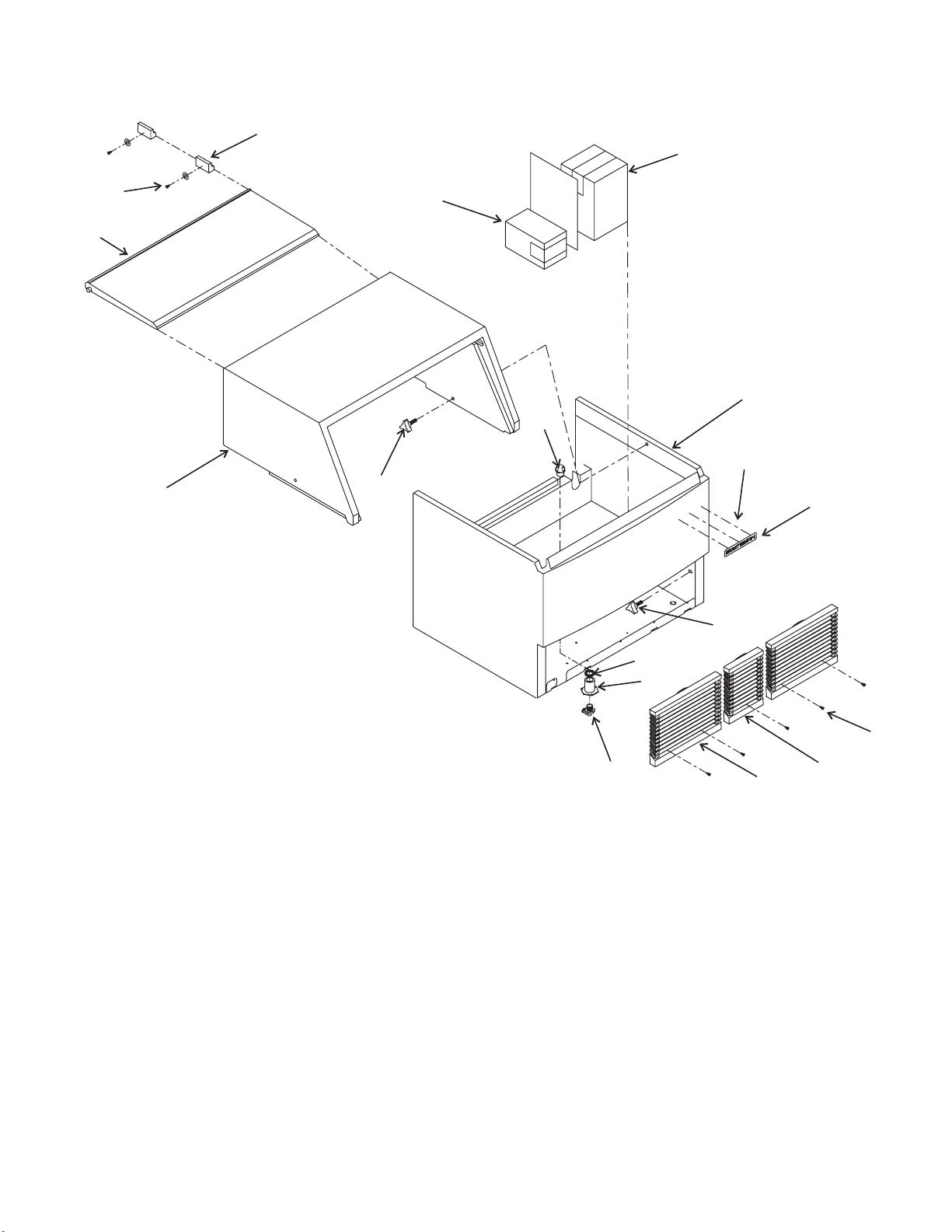
Cabinet
17
13
14
12
3
16
Item Part
Number Number Description
1 A37051-020 Bin, includes items 2 thru7&11
2 15-0711-02 Emblem
3 03-1675-03 Knob
4 02-2809-02 Drain top
5 02-4193-01 Flat washer
6 02-3108-01 Drain fitting
7 16-0822-01 Elbow
8 02-3458-01 Center grill
9 02-3153-01 Grill
10 03-1638-03 Screw
11 03-1562-01 Speed clip
12 A37050-021 Hood, includes items 3, 14, and 15
13 02-3439-01 Door
14 03-1419-22 Screw
15 19-0629-02 Door stop
16 KLP2 Leg kit
17 02-3253-01 Scoop
1
4
11
2
3
5
6
10
7
9
8
September 2005
Page 2
Page 3

SCE275 Service Parts
Air Cooled
1
5
7
6
2
3
Item Part
Number Number Description
1 A36742-001 Fan shroud
2 02-3193-01 Air filter
3 18-8782-01 Condenser
4 18-8773-01 Fan blade
5 A37320-001 Fan motor bracket
6 12-1681-23 Fan motor, 115/60 Hz
12-1681-04 Fan motor, 50 Hz
12-1681-04 Fan motor, 208-230/60
7 A31828-004 Drain fitting
4
September 2005
Page 3
Page 4

SCE275 Service Parts
Water Cooled
3
2
1
4
2
5
Item Part
Number Number Description
1 A31878-001 Drain fitting
2 03-1645-02 Screw
3 11-0478-21 Water regulating valve
4 16-0401-00 Elbow
5 18-8803-25 A - E series water cooled condenser
18-8871-21 F & higher series water cooled condenser
September 2005
Page 4
Page 5

SCE275 Service Parts
1
Refrigeration Components
2
3
7
5
7
4
Item Part
Number Number Description
1 12-2471-21 Hot gas valve w/coil
12-2719-23 Coil for hot gas valve
2 19-0599-04 Insulation, order 2 units
3 16-1009-22 TXV
4 02-3319-01 Drier
5 A36637-001 Suction line
6 11-0501-21 Hi pressure cut out (WC)
7 12-2556-21 Thermistor
6
January 2003
Page 5
Page 6

20
SCE275 Service Parts
Water System
1
18
17
16
14
13
15
22
25
12
23
24
Item Part
Number Number Description
1 02-3547-01 Water hose
2 02-3383-23 Float stem
3 12-2556-21 Thermistor
4 11-0539-21 Water level sensor
3
11
19
9
9a
8
10
.125 MIN-.312 MAX
DO NOTALLOW PROBE TO TOUCH
INS IDE W A LL OF TUBE
2
4
5
7
6
21
24
5 12-2586-24 Water pump, 115/60
12-2586-25 Water pump, 50 Hz
12-2586-25 Water pump, 208-230/60
6 02-3388-06 Pump bracket
7 02-3341-01 Float
8 02-3388-04 Pump bracket
9 02-3610-01 Adjusting nut
02-3537-01 Stand pipe
9a 02-3360-01 Nut
10 13-0617-56 O-ring
11 02-3544-01 Drain fitting
12 02-3548-01 Drain hose
13 02-3626-21 Bin sensor set
14 02-3538-02 Rear trough
15 02-3538-01 Front trough
16 A36939-020 Rear evaporator
17 02-2527-01 Water dist. tube
18 A29703-001 Water manifold
19 A36938-020 Front evaporator
20 13-0840-01 Plug
21 02-3674-01 Evaporator cover
22 02-3337-03 Deflector
23 02-3528-01 Housing
24 03-1691-01 Nylon screw
25 02-3737-01 Filler gasket
January 2003
Page 6
Page 7

SCE275 Service Parts
Compressor, Controller, Water Valve
1
4
3
11
14
Item Part
Number Number Description
1 13-0910-01 Gasket
2 13-0911-01 Tube seal
3 13-0912-01 Tube seal
4 13-0913-01 Water inlet tube seal
5 A36784-001 Evaporator housing
6 12-2838-22 Controller
7 03-1638-03 Screw
8 03-1645-02 Screw
9 A36657-001 Bracket
10 16-0832-21 Service valve
10a 16-0832-03 Port cap
10b 16-0832-02 Stem cap
11 A36608-001 Back panel
12 03-1677-01 Screw - inserts from below
03-1406-01 Hex nut
03-1407-01 Washer
2
6
Controller location, G
series and up
5
7
6
15
8
16
12
13
10
9
13 18-0108-41 Mounting sleeve
18-2300-27 Grommet
14 12-2548-01 Inlet water valve
15 18-8774-21 Compressor, 115/60
18-8774-23 Overload for 115/60
18-8774-26 Compressor, 230/50/1
18-8774-27 Overload for 50 Hz
18-8774-22 Compressor 208-230/60
18-8774-28 Overload for 208-230/60
16 02-3461-01 Inlet water hose
January 2006
Page 7
Page 8

SCE275 Service Parts
Electrical Box
2
5
8
6
Item Part
Number Number Description
1 12-2836-01 Transformer, 115/60
12-2836-02 Transformer, 230/60 or 50 Hz
2. 12-2469-01 Contactor
3 12-2563-01 Control box harness
4 18-1901-55 Start capacitor, 115/60 Hz
18-1901-56 Start capacitor, 50 Hz
5 18-1902-45 Run capacitor, 115/60 Hz
18-1902-52 Run capacitor, 50 Hz
18-1902-52 Run capacitor 208-230/60
6 18-1903-52 Potential Relay, 115/60 Hz
18-1903-53 Potential Relay, 50 Hz
7 12-1638-14 Power cord, 115/60 Hz
12-1638-18 Power cord, 208-230 60 or 50 Hz
8. 18-8835-01 PTCR
9. A36855-001 Cover for control box
1
4
January 2003
Page 8
Page 9

SCE275 Service Parts
Wire Harnesses
Wire Harnesses are NOT ILLUSTRATED, select by
model number and description
A through F series models have single harnesses
G series 60 Hz have single harnesses
G series 50 Hz have split harnesses
Part Number Description
12-2620-01 Main wire harness WC forA-Fseries
12-2619-01 Main wire harness AC forA-Fseries
12-2900-01 Main wire harness AC for G series 60 Hz
12-2901-01 Main wire harness WC for G series 60 Hz
12-2894-01 24 volt wire harness, AC for G series 50 Hz
12-2893-01 Pump wire harness, WC for G series 50 Hz
12-2895-01 Pump and fan wire harness, AC for G series 50 Hz
12-2892-01 24 volt wire harness, WC for G series 50 Hz
January 2003
Page 9
Page 10

SCE275 Service Parts
Wiring Diagram, A series
January 2003
Page 10
Page 11

SCE275 Service Parts
Schematic Diagram
January 2003
Page 11
Page 12

SCE275 Service Parts
60 Hz Wiring Diagram: D, E, F and G Series
January 2003
Page 12
Page 13

50 Hz Wiring Diagram: - 6E, -6F, and -6G
17-2935-01
*
SCE275 Service Parts
COIL
CONTACTOR
LINE
TRANSFORMER
L1
24V
WATE R VA LVE
HOT GAS VALVE
HI PRESS CUT OUT
WATERCOOLED ONLY
ELECTRONIC CONTROL
BIN
BIN
WATER
SUMP
TEMP
DISCHARGE
TEMP.
FULL
X-MIT
FULL
RCV.
LEVEL
SENSOR
FAN
FAN
WATER
T1
MOTOR
(AC ONLY)
MOTOR
(AC ONLY)
PUMP
PTCR
RUN
CAP.
COMPRESSOR
COMPRESSOR MAY NOT START IF
PTCR IS NOT ALLOWED TO COOL.
PTCR WILL BE HOT.
CAUTION:
O
HOT GAS
SOLENOID
GRAY
MOT
FAN
A\C
ONLY
MOT
FAN
MOT
PUMP
POWER SUPPLY
GN
RUN
CAP
O
W
BK
W
R
BK
EXTERNAL
PROTECTOR
COMPRESSOR
BK
R
C
Y
S
R
W
BK
STARTWINDING
RUN WINDING
BK
BK
6
W/R
1
5
2
LINE
LOAD
12
TRANSFORMER
W/R
7
8
11
BK
L1
T1
T2 L2
CONTACTOR
Y
Y
PTCR
W (AC ONLY)
W
AIR COOLED ONLY
BK
BK
(AC ONLY)
BN
BU
O
W/Y
FUSE
(3A)
*
PROPER VOLTAGE REQUIREMENTS
AND MAXIMUM FUSE SIZE
SEE NAMEPLATE FOR
V
REQUIRED TO DISCONNECT ALL POWER TO THIS UNIT.
MORE THAN ONE DISCONNECT MEANS MAYBE
CAUTION:
HI-PRESS
CUT OUT
WATER COOLED ONLY
Y
4321
9
5
54321
CONTROL
ELECTRONIC
3
4
321
321
2
54321
COMMUNICATIONS
1
2
1
PORT
3
7654321
8
7
6
O
WATER
SOLENOID
SUMP TEMP.
LB
SENSOR
DISCHARGE
TEMP.
SENSOR
BIN FULL
TRANSMITTER
BIN FULL
RECIEVER
WATER
LEVEL
SENSOR
USE COPPER CONDUCTORS ONLY
THIS UNIT MUST
BE GROUNDED.
January 2003
Page 13
 Loading...