


NSE650 SERVICE PARTS
This parts list contains the service part numbers
and wiring diagrams for this model. Check the
model number of the unit being serviced to be sure
that this list is the correct one.
Note: The liquid line filter drier listed in
this parts list is designed for this
refrigeration system. Premature failure
may result if the wrong drier is used.
TABLE OF CONTENTS
Cabinet . . . . . . . . . . . . . . . . . . . . . . . . . . . . . . . . . . . Page 2
Refrigeration . . . . . . . . . . . . . . . . . . . . . . . . . . . . . . . . . Page 3
Water System . . . . . . . . . . . . . . . . . . . . . . . . . . . . . . . . Page 4
Evaporator . . . . . . . . . . . . . . . . . . . . . . . . . . . . . . . . . Page 5
Gearmotor . . . . . . . . . . . . . . . . . . . . . . . . . . . . . . . . . Page 6
Ice Level Sensor . . . . . . . . . . . . . . . . . . . . . . . . . . . . . . . Page 7
Control Box . . . . . . . . . . . . . . . . . . . . . . . . . . . . . . . . . Page 8
Wiring Diagrams . . . . . . . . . . . . . . . . . . . . . . . . . . . . . . . Page 9
NSE650 SERVICE PARTS
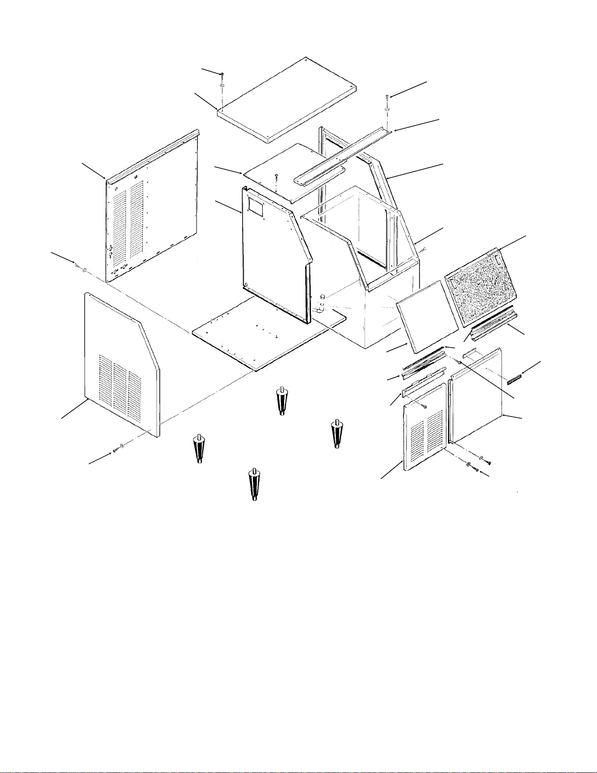
Cabinet
1
2
1
3
21
18
6
5
7
11
12
13
4
8
9
10
14
15
22
16
19
ITEM PART
NUMBER NUMBER DESCRIPTION
1 03-1419-19 Screw
2 A30494-004 Top Panel, sandalw ood
A30494-015 Top panel, gra y
A30494-002 Top Panel, Stainless
3 A37397-001 Door Track Assemb ly
4 A24800-004 Rt. Side Panel, sandalwood
A24800-015 Right side panel, gra y
A24800-002 Rt. Side Panel, St ainless
5 A34422-001 Bin Cover
6 A35913-001 Back Panel
7 A33952-001 Retainer
8 A34421-001 Ice Storage Bin
9 02-2130-03 Door , Brown
02-2130-02 Door, Gray (for Stainless)
02-2130-04 Door , gray
10 15-0620-01 Moulding Right
11 A30497-006 Upper front panel, s-wood
A30497-015 Upper front panel, gray
A30497-002 Upper front panel, stainless
March 1998
Page 2
17
20
12 15-0706-01 Moulding, left
13 A33958-001 Bracket
14 15-0324-00 Black insert 37"
15 15-0711-01 Emblem for sandalwood
15-0711-02 Emblem for st ainless or gray
16 A24794-004 Rt. Fr ont Panel, sandalwood
A24794-015 Right front panel, gray
A24794-002 Rt. Fr ont Panel, stainless
17 A33968-001 Lower left front, sandalwood
A33968-015 Lower left front panel, gra y
A33968-002 Lower left front, st ainless
18 A27034-004 Left side panel, sandalwood
A27034-015 Left side panel, gray
A27034-002 Left side panel, stainless
19 03-1531-01 Screw
20 03-1419-16 Screw
21 03-1638-03 Screw
22 03-1419-17 Screw
5
4
NSE650 SERVICE PARTS
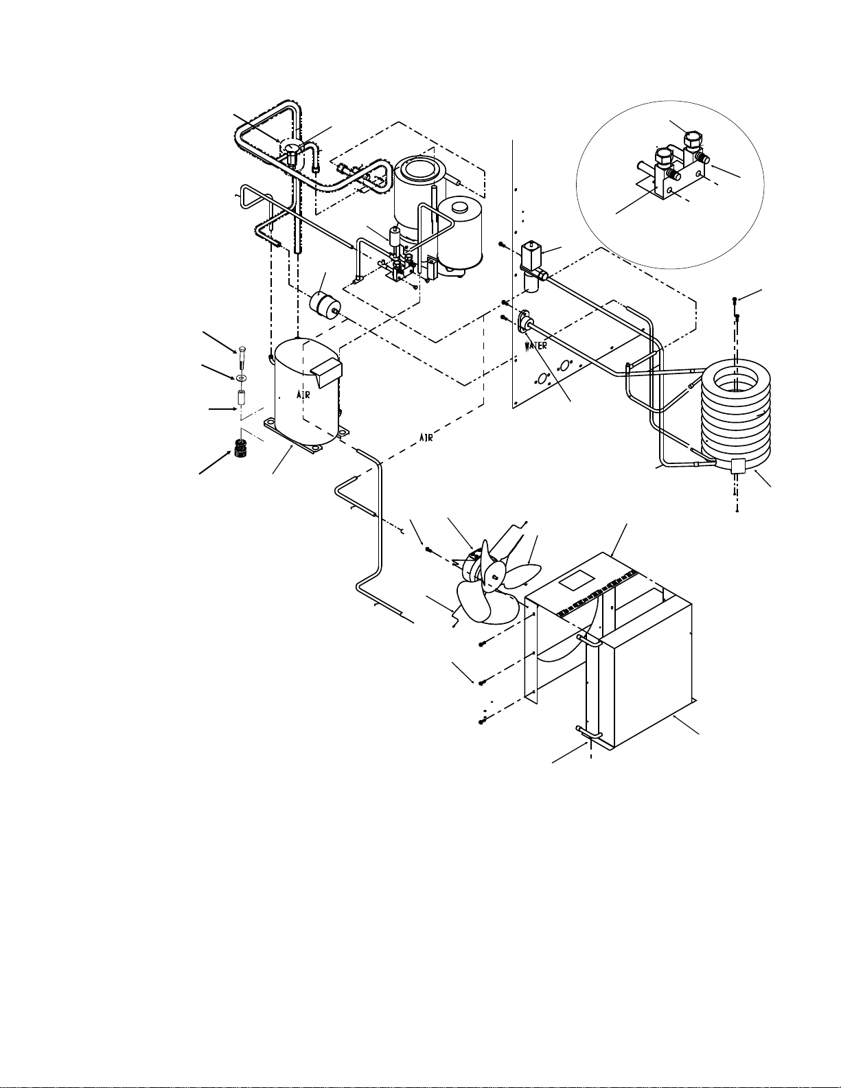
Refrigeration System
18
15
17
16
21
14
19
20
22
6
23
1
2
3
Access Valve
Detail
ITEM PART
NUMBER NUMBER DESCRIPTION
1 16-0832-02 Stem cap
2 16-0832-03 Core cap
3 16-0832-20 Access valve
4 03-1645-01 Screw
5 18-3306-22 Water cooled condenser
6 11-0478-21 Water regulating valve
7 18-5105-11 Fan Motor, 115/60/1
8 18-3732-02 Fan Blade
9 A35911-001 Fan Shroud
10 18-8732-01 Air cooled condenser
11 02-3333-01 Fan Motor Bracket
12 03-1404-03 Screw
13 03-1645-01 Screw
14 18-8721-21 Compressor 115/60/1
18-8711-50 Compressor overload
15 18-2200-28 Grommet
16 18-2200-27 Sleeve
17 03-1405-40 Bolt
18 03-1408-29 Washer
19 02-3319-02 Drier
20 11-0488-21 Thermo Expansion valve
21 A32961-020 Insulation Kit (3 piece)
22 11-0485-21 Hi Pressure Cut Out
23 A31828-002 Drain casting
13
11
7
12
8
13
9
10
July 1994
Page 3

NSE650 SERVICE PARTS
1
2
Water System
17
16
18
20
21
11c
19
14
11b
6
8
11a
15
5
12
11
4
9
10
3
7
ITEM PART
NUMBER NUMBER DESCRIPTION
1 03-1394-01 Pal Nut
13
2 A27318-001 Inlet Water Fitting
3 02-3266-22 Plunger & seat
4 A33101-022 Water Level Sensor
5 16-0162-01 Strainer
6 02-3266-20 Reservoir Assy, Complete
7 02-3266-21 Float Assembly
22
25
8 A34037-001 Reservoir Bracket
9 13-0840-01 Plug
10 13-0674-06 Drain Tubing 18"
11 13-0674-06 Tubing 5"
11a 13-0079-03 Tubing, 17"
11b 13-0079-03 Tubing, 17"
11c 13-0079-03 Tubing, 8"
23
24
12 02-2814-08 Clamp
13 16-0670-02 Tee
14 A32777-001 Retaining Ring
15 05-0501-01 Preformed Tubing
16 A32050-001 Drain Pan
17 13-0704-00 Gasket
18 13-0871-01 Water Shed
19 02-0929-03 Water Seal
20 A31828-005 Drain Casting
21 A31828-007 Drain Casting
22 02-2809-01 Drain top
23 A27018-001 Drain
24 13-0674-06 Drain Tube 6"
25 02-1338-00 Hose Clamp
November 2003
Page 4

8
17
18
19
21
NSE650 SERVICE PARTS
Evaporator
ITEM PART
NUMBER NUMBER DESCRIPTION
1 03-1420-03 Cap Screw
03-1417-13 Lockwasher
2 A33194-020 Evaporator
3 A32962-001 Insulation Half
4 A32962-002 Insulation Half
5 02-0929-03 Water Seal
6 A32777-001 Retaining ring for seal
7 A32050-001 Drip Pan
1 2
4
3
ITEM PART
NUMBER NUMBER DESCRIPTION
8 13-0704-00 Gasket
9 13-0868-01 Water Shed
10 02-2977-01 Lip Seal
11 13-0617-54 O-Ring
12 A32900-020 Breaker
(includes 10 & 14)
13 03-1544-08 Soc. head screw
14 13-0617-45 O-Ring
15 03-1405-52 Hex Cap Screw
16 02-3001-01 Ice Sweep
17 13-0871-01 Water Shed
18 02-2978-01 Lip Seal
19 02-3128-01 Breaker cover
20 13-0617-52 O-Ring
21 08-0660-01 Auger Stud
22 A34559-020 Bearing
23 02-3002-01 Auger
10
15
11
5
6
7
9
13
12
16
14
20
22
23
July 1994
Page 5

NSE650 SERVICE PARTS
Gearmotor Assembly
1
8
*NOTE: GEARCASE
COVER INCLUDES
COVER, OUTPUT
SHAFT, KEY, OUTPUT
GEAR, BEARINGS
AND SEAL
2
9
10
3
4
11
5
12
ITEM PART
NUMBER NUMBER DESCRIPTION
1 13-0868-01 Water Shed
6
2 A32379-026 Bolt
3 A32379-022 Gearcase Cover*
4 A32379-024 1st Gear and Bearings
5 A32379-023 2nd Gear and Bearings
6 A32379-021 Gasket
7 A32379-020 Gearcase
8 12-2430-24 Centrifugal Switch, Emerson
12-2430-44 Centrifugal sw, GE split phase
7
9 12-2430-21 Drive Motor 115 v
10 12-2430-29 Rotor Bearing, Emerson
12-2430-49 Rotor bearing, GE split phase
11 A32379-028 Seal, not used on replacement
gear reducers and covers after 2/2000
12 A32379-027 Oil, 1 Container
13 A33220-021 Complete Assy 115 v
November 2003
Page 6
A33220-030 Gears, oil & cases, no motor

NSE650 SERVICE PARTS
Ice Level Sensors and Ice Chute
2
3
9
4
6
10
5
8
1
ITEM PART
NUMBER NUMBER DESCRIPTION
1 A35419-020 Strap kit
2 A34969-001 Bail clamp
3 02-3268-01 Drain tube clip holder
4 02-2957-02 Ice chute cover
5 02-2958-01 Ice chute body
6 A34630-021 Ice level sensors
7 A33102-001 Insulation
8 A32963-001 Insulation half
9 13-0867-01 Grommet
10 03-1531-01 Screw
11 02-2973-01 Chute extension
11
7
6
July 1994
Page 7

NSE650 SERVICE PARTS
Control Box
2
3
1
6
6
5
4
14
11
8
9
10
12
13
7
ITEM PART
NUMBER NUMBER DESCRIPTION
1 03-1419-10 Screw
2 18-1901-03 Start Capacitor
3 18-2200-38 Start Capacitor Cap
4 18-2200-39 Start Capacitor Bracket
5 13-0577-00 Grommet
6 12-1213-11 Bushing
7 12-2048-01 Contactor
8 03-1531-01 Screw
9 11-0447-20 Low Pressure Control
8
ITEM PART
NUMBER NUMBER DESCRIPTION
10 12-0426-01 Master Switch
11 12-2285-21 Transformer
12 18-1903-50 Potential Relay
13 12-2350-01 Stand off
14 A37750-021 Circuit Board
NOT ILLUSTRATED
15 12-2337-05 Wire Harness, circuit
board to safety circuit
16 12-2340-02 Wire Harnes, circuit
board to transformer
17 18-1902-45 Run capacitor
(mounts behind control box)
September 2000
Page 8

NSE650 SERVICE PARTS
Component Layout Diagram
July 1994
Page 9

NSE650 SERVICE PARTS
Schematic Diagram
July 1994
Page 10
 Loading...