

Page 1

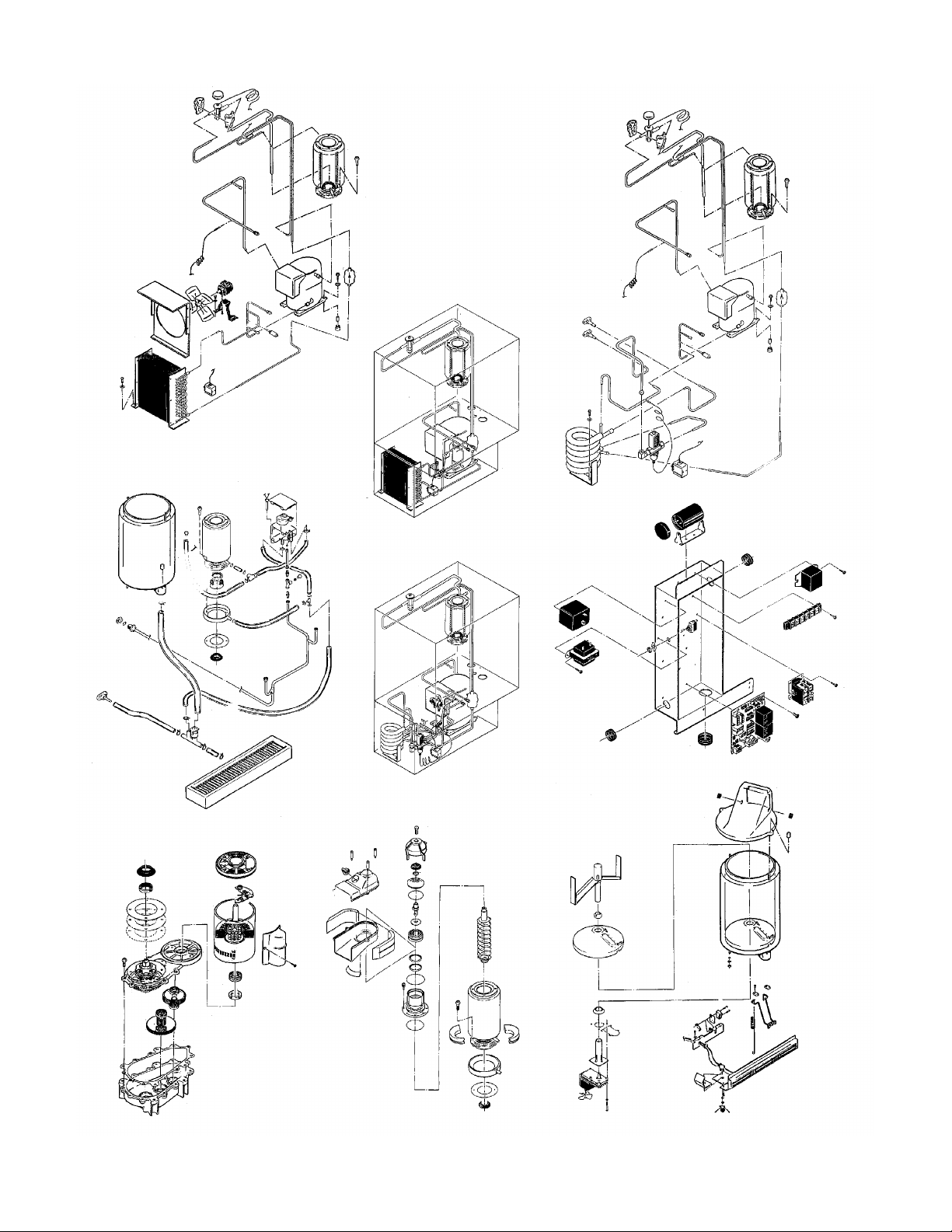
ND650 SERVICE PARTS
This parts list contains the service parts and wiring
diagrams for this model. Check the model number
of the machine requiring the parts to be sure that
this is the correct parts list.
TABLE OF CONTENTS
Cabinet Assembly . . . . . . . . . . . . . . . . . . . . . . . . . . . . . . Page 2
Air Cooled Refrigeration . . . . . . . . . . . . . . . . . . . . . . . . . . . . Page 3
Water Cooled Refrigeration . . . . . . . . . . . . . . . . . . . . . . . . . . . Page 4
Ice Dispensing . . . . . . . . . . . . . . . . . . . . . . . . . . . . . . . . Page 5
Evaporator . . . . . . . . . . . . . . . . . . . . . . . . . . . . . . . . . Page 6
Gearmotor Assembly . . . . . . . . . . . . . . . . . . . . . . . . . . . . . Page 7
Control Box . . . . . . . . . . . . . . . . . . . . . . . . . . . . . . . . . Page 8
Water System . . . . . . . . . . . . . . . . . . . . . . . . . . . . . . . . Page 9
Water Station and Soda Valve Kit . . . . . . . . . . . . . . . . . . . . . . . . Page 10
Wiring Diagrams . . . . . . . . . . . . . . . . . . . . . . . . . . . . . . . Page 11-12
Page 2
ND650 SERVICE PARTS
January 2006
Page 1
Page 3
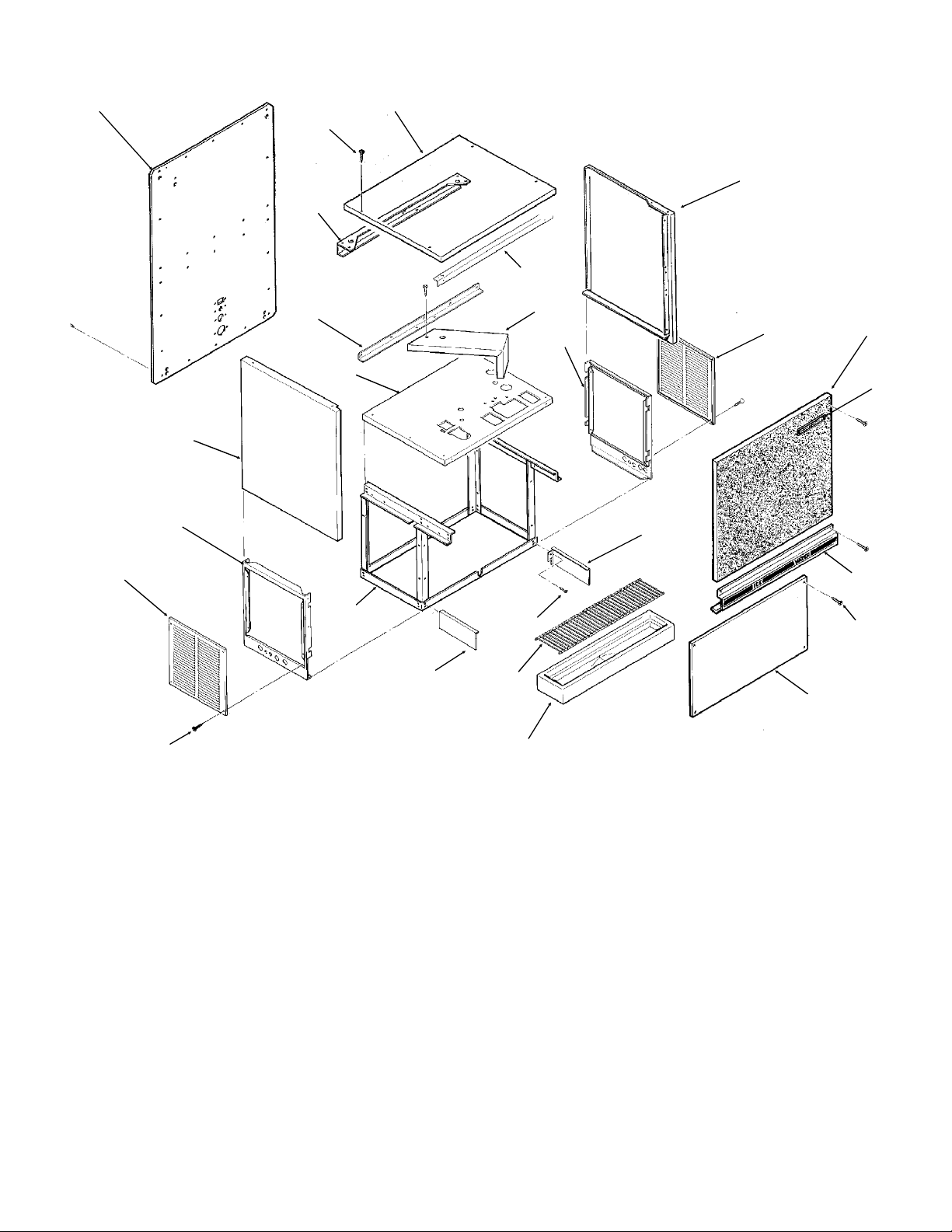
ND650 SERVICE PARTS
Cabinet Assembly
1
3
4
2
5
7
8
11
12
23
6
22
18
ITEM PART
NUMBER NUMBER DESCRIPTION
1 A33112-001 Back Panel, painted
A33112-002 Back Panel, stainless
2 A32948-001 Top Panel, painted
A32948-002 Top Panel, stainless
3 03-1419-09 Panel screw
4 A32938-001 Hanger Brace
5 A33109-003 Rt. side panel, painted
A33109-004 Rt. side panel, stainless
6 A33113-001 Service panel, painted
A33113-002 Service panel, stainless
7 A32939-001 Front Brace
8 A32940-001 Support angle
9 A33107-001 Gearmotor Support
10 A32953-001 Rt. side lower, painted
A32953-002 Rt. side lower, stainless
17
9
6
10
16
18
19
15
20
ITEM PART
NUMBER NUMBER DESCRIPTION
11 A32956-001 Upper plate assembly
12 A33109-001 Lt. side panel, painted
A33109-002 Lt. side panel, painted
13 A33108-001 Up front panel, cork
A34394-001 Up front panel, stainless
14 A33198-001 Control panel assembly
15 A32944-001 Lower front panel
16 A34917-001 RH sink support
17 A34917-001 LH sink support
18 03-1419-17 Screw
19 02-2951-01 Grill
20 02-2944-02 Sink
21 15-0711-01 Emblem
22 A32958-001 Lower frame assy
23 A32952-001 Lt side lower, painted
A32952-002 Lt side lower, stainless
13
21
14
3
January 2006
Page 2
Page 4
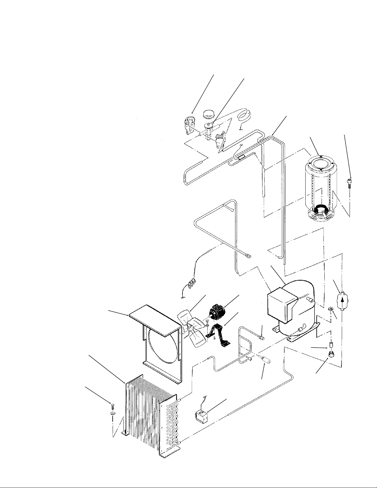
ND650 SERVICE PARTS
Air Cooled Refrigeration
ITEM PART
NUMBER NUMBER DESCRIPTION
1 A32961-020 Insulation Kit (3 piece)
2 16-0780-21 Thermo Expansion Valve
3 A33330-001 Suction Line
4 A33194-020 Evaporator
5 03-1420-03 Screw
6 18-5700-01 Compressor
7 03-1406-10 Hex nut
8 02-3319-02 Dryer
9 18-2200-27 Mounting Sleeve
10 18-2200-28 Mounting Grommet
11 18-0559-07 Fan Motor
12 18-0422-00 Fan Bracket
13 11-0447-20 Low Pressure Cont.
14 18-0137-02 Fan Blade
15 A33110-001 Fan Shroud
16 18-8100-01 Condenser
17 03-1406-10 Nut
18 16-0560-00 Valve Core
16-0563-00 Valve Cap
19 11-0446-22 Hi Press. Cut Out
1
2
3
4
5
17
16
15
14
13
11
12
19
18
6
8
7
9
10
January 2006
Page 3
Page 5
ND650 SERVICE PARTS
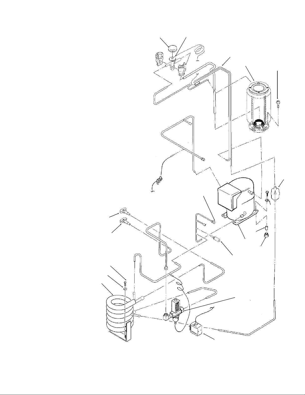
Water Cooled Refrigeration
ITEM PART
NUMBER NUMBER DESCRIPTION
1 A32961-020 Insulation Kit (3 piece)
2 16-0780-21 Thermo Exp. Valve
3 A33330-001 Suction Line
4 A33194-020 Evaporator
5 03-1420-03 Screw
6 02-3319-02 Dryer
7 03-1406-10 Hex Nut
8 18-2200-27 Mounting Sleeve
9 18-2200-28 Mounting Grommet
10 18-5700-01 Compressor
11 16-0560-00 Valve core
16-0563-00 Valve Cap
12 11-0446-22 High Press. Cut Out
13 11-0424-01 Water Reg. Valve
14 11-0447-20 Low Press. Control
15 A31828-001 Adaptor Flange
16 03-1645-01 Screw
17 03-1410-03 Lock washer
18 18-3305-25 Condenser
19 A31828-002 Adaptor Flange
1
2
3
4
5
18
15
17
19
16
6
11
7
8
10
9
12
13
January 2006
Page 4
14
Page 6

ND650 SERVICE PARTS
Ice Dispensing
2
18
17a
22
Only used with agitator
16
19
Agitator, no longer
available. Replace
with item 18.
17
15
1
20
3
4
5
6
14
13
ITEM PART
NUMBER NUMBER DESCRIPTION
1 13-0866-01 Grommet, Bin Control
2 A34493-003 Bin top
3 03-0255-00 Wing Nut
4 A34496-002 Storage Bin Assembly
5 03-1406-09 Hex nut
03-1410-03 Lock washer
6 02-2950-01 Arm Clamp
7 02-2076-01 Glass Filler Lever use
with 12-1642-00 switch (thru 1990)
02-3167-01 Glass filler lever, use
with 12-2409-01 switch (beg. Jan. 91)
8 A33198-001 Control Panel Assy
9 02-3022-01 Spring
11 A24258-003 Potentiometer
10 02-1810-00 Knob
12 12-1642-00 Microswitch thru 1990
12-2409-01 Microswitch (current)
21
13 12-2677-01 Vane Drive Motor**
14 02-1971-00 Bracket
15 13-0747-00 Water Shed
16 A32657-001 Bin Bottom
17* 02-2998-01 Bushing (used with agitator)
17a* 02-3327-01 Bearing, used with vane
18* A37267-001 Ice vane, includes bearing**
19 A37710-021 Ice Level Sensor
20 15-0672-01 Ice Decal
21 A33351-001 Switch Plate
22* obsolete Drive shaft
*Used with agitator, not vane
**Vane and Vane Drive Motor changed 4/97. Not
interchangeable with prior design. Order both items 13
and 18 to replace agitator or prior vane and/or motor.
January 2006
Page 5
12
7
9
11
8
20
10
Page 7

18
19
17
ND650 SERVICE PARTS
Evaporator
15
16
29
2
4
6
8
1
3
5
21
7
9
20
ITEM PART
NUMBER NUMBER DESCRIPTION
1 03-1405-52 Hex Cap Screw
2 02-3001-01 Ice Sweep
3 13-0871-01 Water Shed
4 02-2978-01 Lip Seal
5 08-0650-20 Breaker Cover
6 13-0617-54 O-Ring
7 08-0660-01 Auger Stud w/ item 8
8 part of item 7 Thrust Washer
9 A34559-020 Bearing
10 02-2977-01 Lip Seal
11 13-0617-52 O-Ring
12 03-1544-08 Soc. Head Screw
13 A32900-020 Breaker - includes 9 & 10
14 13-0617-45 O-Ring
15 02-2933-01 Hex Stud
16 A32891-020 Switch Assembly
17 02-2930-01 Ice Chute Cover
18 A32963-001 Insulation top (1/2)
19 02-2943-01 Ice Chute Body
20 A33102-001 Insualation Collar Inside
A33210-001 Rubber Band
21 A38071-021 Auger
22 A33194-020 Evaporator
23 03-1420-03 Screw
18
10
12
30
14
10
11
13
22
23
25
26
28
24 A32962-001 Insulation (1/2)
25 A32962-002 Insulation (1/2)
26 A32050-001 Drip Pan
27 13-0704-00 Drip Pan Gasket
28 13-0868-01 Water Shed
29 13-0617-53 O-Ring
30 03-1408-26 Washer
24
27
January 2006
Page 6
Page 8

ND650 SERVICE PARTS
Gearmotor Assembly
1
2
*NOTE: GEARCASE
COVER INCLUDES
COVER, OUTPUT
SHAFT, KEY, OUTPUT
GEAR, BEARINGS
AND SEAL
4
5
3
10
11
15
12
14
6
13
7
ITEM PART
NUMBER NUMBER DESCRIPTION
1 13-0868-01 Water Shed
2 A32379-029 Seal
3 no number End bell
8
4 A32379-026 Bolt
5 A32379-022 Gearcase Cover*
6 A32379-024 1st Gear and Bearings
7 A32379-023 2nd Gear and Bearings
8 A32379-021 Gasket
9 A32379-020 Gearcase
10 A32898-020 Centrifugal Switch, GE PSC
12-2430-24 Start switch, Emerson
9
12-2430-44 Start switch, GE split phase
11 12-2430-21 Drive Motor 115 v
12 A32898-030 Rotor Bearing, GE PSC
12-2430-29 Rotor bearing, Emerson
12-2430-49 Rotor bearing, GE split phase
13 A32379-028 Seal, not used in replacement
gear reducers & covers afater 2/2000
14 A32379-027 Oil, 1 Container
15 12-2314-22 Capacitor- GE only
16 A33220-021 Complete Assy 115 v
A33220-030 Gears, oil and cases. No motor.
January 2006
Page 7
Page 9

ND650 SERVICE PARTS
1
2
7
13
Control Box
3
4
5
6
8
4
ITEM PART
NUMBER NUMBER DESCRIPTION
1 18-1901-47 Start Capacitor
2 18-2200-38 Cap for start capacitor
3 18-2200-39 Start Cap. Bracket
4 12-1213-10 Bushing
5 A27857-001 Time Delay Relay
6 12-0813-03 Terminal Strip
7 18-1903-31 Potential Relay
8 12-2285-21 Transformer
9 12-1213-12 Bushing
10 A32976-020 Circuit Board
11 A33219-001 Standoff
12 12-2469-0
3 Contactor
13 12-0426-01 Switch
12
11
10
9
Not Illustrated:
14 12-2337-01 Plug Assembly, Circuit
Board to Low Pressure
Control and Spout Sw.
15 12-2340-01 Plug Assembly, Circuit
Board to Transformer
16 12-2298-01 Lockswitch for -1AG
(Government Units)
17 A33127-001 Control Box Cover
January 2006
Page 8
Page 10

ND650 SERVICE PARTS
Water System
24
15
3
2
23
9
11
13
1
22
26
14
1
25
1
21
8
1
10
12
4
5
6
11
7
1
8
1
20
1
18
1
19
16
ITEM PART
NUMBER NUMBER DESCRIPTION
1 02-2814-06 Clamp
2 13-0859-01 Plug
3 A33101-021 Water Level Sensor
4 02-2936-01 Reservoir Cover
5 A32922-020 Float Assy, complete
6 A32929-020 Reservoir Assy, complete
7 13-0674-06 Tubing, requires 8"
8 16-0670-02 Tee
9 13-0674-09 Tubing, requires 20"
10 13-0079-03 Tube Assy
11 02-2814-08 Clamp
17
ITEM PART
NUMBER NUMBER DESCRIPTION
12 13-0079-03 Drain Tube, req. 28"
13 13-0674-09 Evap. Inlet Tube, req 4"
14 13-0079-01 Bin Drain Tube, req. 15"
15 A31757-001 Drain Casting
16 13-0079-01 Sink Tube, req. 1-3/4"
17 02-2951-01 Grill
18 A34557-001 Drain
19 02-2944-02 Sink
20 13-0079-01 Drain Tube, req. 8"
21 16-0162-00 Strainer
22 13-0674-09 Drain Tube, req. 14.5"
23 13-0230-00 Rubber cap
24 A27318-001 Inlet Fitting (only)
25 02-0929-03 Water Seal
26 A32777-001 Retaining Ring
January 2006
Page 9
Page 11

ND650 SERVICE PARTS
WATER GLASS FILLER STATION
(KWGFA)
ITEM PART
NUMBER NUMBER DESCRIPTION
1 02-2076-01 Glass Filler Lever
2 02-3022-01 Spring
3 12-1646-01 Solenoid Assembly
4 12-1642-00 Switch (mounted to plate)
12-2409-01 Switch (mount to base)
5 A29886-001 Valve plate
6 15-0672-01 Label
5
6
KIT:KV5H-30 ELECTRIC VALVE KIT
ITEM PART
NUMBER NUMBER DESCRIPTION
1 02-2128-01 Carb. Manifold Assy
2 A20368-000 Faucet Bracket
3 02-1205-19 Faucet
4 02-1205-16 Faucet
5 02-1205-17 Faucet
6 A30209-001 Syrup Line
7 A20547-000 Carb.Water Line
8 12-1809-00 Transformer
Note: Scotsman does not stock parts
for valves.Determine the model of
valve on your unit and order parts
from:
McCann’s Engineering & Mfg.Co.
2570 Colorado Blvd.
Los Angeles, CA 90039
October 1997
Page 10
Page 12

Component Layout Diagram
ND650 SERVICE PARTS
October 1997
Page 11
Page 13

Schematic Diagram
ND650 SERVICE PARTS
October 1997
Page 12
Page 14

ND650 SERVICE PARTS
October 1997
Page 13
Page 15

ND650 SERVICE PARTS
Schematic Diagram
October 1997
Page 14
 Loading...