

Page 1

CM500 SERVICE PARTS
This section contains the parts illustrations and
parts lists for the CM500.
A "no number" designation, when found in the part
number column, indicates the part in question is
not available from Scotsman as an assemby. This
designation is used only for clarity in making the
list.
When ordering parts, to avoid costly delays and
errors, give the part number, the complete
description as shown in the list, and the quantity of
each part or assembly required.
CM500’s have been manufactured in "C", "D"
and "E" series (as in CM500AE-1
Check the complete model number to match
up with the correct part number in this list.
"E" series production began in June 1992. Major
differences between the "D" and the "E" are the
compressor and related starting components.
E).
TABLE OF CONTENTS
Exterior Panels . . . . . . . . . . . . . . . . . . . . . . . . . . . . . . . . . . . . . . 2
Interior Panels . . . . . . . . . . . . . . . . . . . . . . . . . . . . . . . . . . . . . . 3
Air Cooled Refrigeration . . . . . . . . . . . . . . . . . . . . . . . . . . . . . . . . . 4
Water Cooled Refrigeration . . . . . . . . . . . . . . . . . . . . . . . . . . . . . . . 5
Water System . . . . . . . . . . . . . . . . . . . . . . . . . . . . . . . . . . . . . . . 6
Control Box . . . . . . . . . . . . . . . . . . . . . . . . . . . . . . . . . . . . . . . . 7
Wiring Diagrams . . . . . . . . . . . . . . . . . . . . . . . . . . . . . . . . . . . . . 8
August 1993
Page 1
PDF compression, OCR, web optimization using a watermarked evaluation copy of CVISION PDFCompressor
Page 2
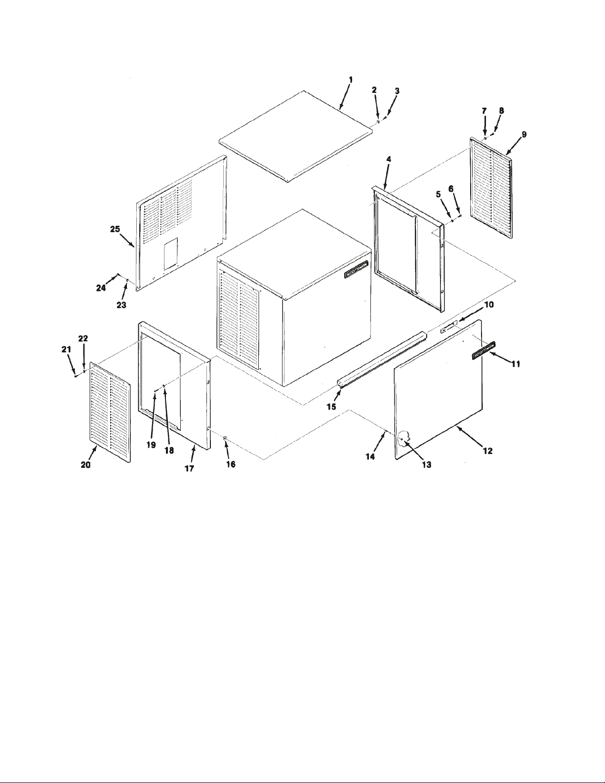
CM500 SERVICE PARTS
CABINET ASSEMBLY: D and E series, C series parts are obsolete.
ITEM PART
NUMBER NUMBER DESCRIPTION
1 A32159-001 Top Panel, Painted
A32159-002 Top Panel, S. S.
2 03-1417-03 Lockwasher
3 03-1531-01 Screw
4 A32162-001 Right End Panel, Paint
A32162-002 Right End Panel, S.S.
5. 03-1417-03 Lockwasher
6 03-1531-01 Screw
7 03-1417-03 Lockwasher
8 03-1404-12 Screw
9 A32161-001 Service Panel, Painted
A32161-002 Service Panel, S.S.
10 03-0271-00 Speed Nut
11 15-0711-01 Emblem
12 A32160-001 Front Panel, Painted
A32160-002 Front Panel, S.S.
November 2003
ITEM PART
NUMBER NUMBER DESCRIPTION
13 03-1406-04 Nut
14 15-0411-00 Strike
15 A32169-001 Front Support
16 02-0836-00 Cabinet Catch
17 A32163-001 Left End Panel, Paint
A32163-002 Left End Panel, S.S.
18 03-1417-03 Lockwasher
19 03-1531-01 Screw
20 A32161-001 Service Panel, sandalwood
A33946-002 Service Panel, gray
Item 20 parts are plastic, fit late D and all E series
21 03-1404-12 Screw
22 03-1412-03 Lockwasher
23 03-1417-03 Lockwasher
24 03-1531-01 Screw
25 A32202-003 Back Panel
Page 2
PDF compression, OCR, web optimization using a watermarked evaluation copy of CVISION PDFCompressor
Page 3
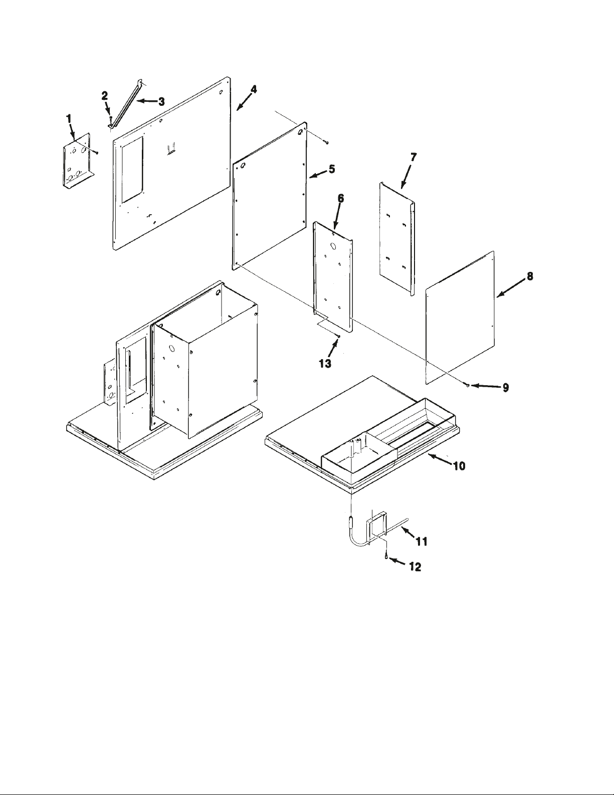
CM500 SERVICE PARTS
CABINET INTERIOR: D and E series, C series parts are obsolete.
ITEM PART
NUMBER NUMBER DESCRIPTION
1 A32166-015 Junction Box Bracket
2 03-1645-01 Screw
3 A32210-001 Support Brace
4 A32158-001 Retainer
5 02-2867-01 Splash Panel
6 A32173-001 Evaporator Bracket, left
7 A32172-001 Evaporator Bracket, right
8 02-3246-01 Evaporator Plate Cover
9 03-0727-09 Thumbscrew
10 A32153-001 Base
11 A32262-001 Bin Thermostat Bracket
12 03-0727-09 Thumbscrew
13 03-1531-02 Screw
November 2003
Page 3
PDF compression, OCR, web optimization using a watermarked evaluation copy of CVISION PDFCompressor
Page 4
Not Illustrated:
Hot Gas Valve Filter, use
began with “E” model, part
number: 02-3231-02
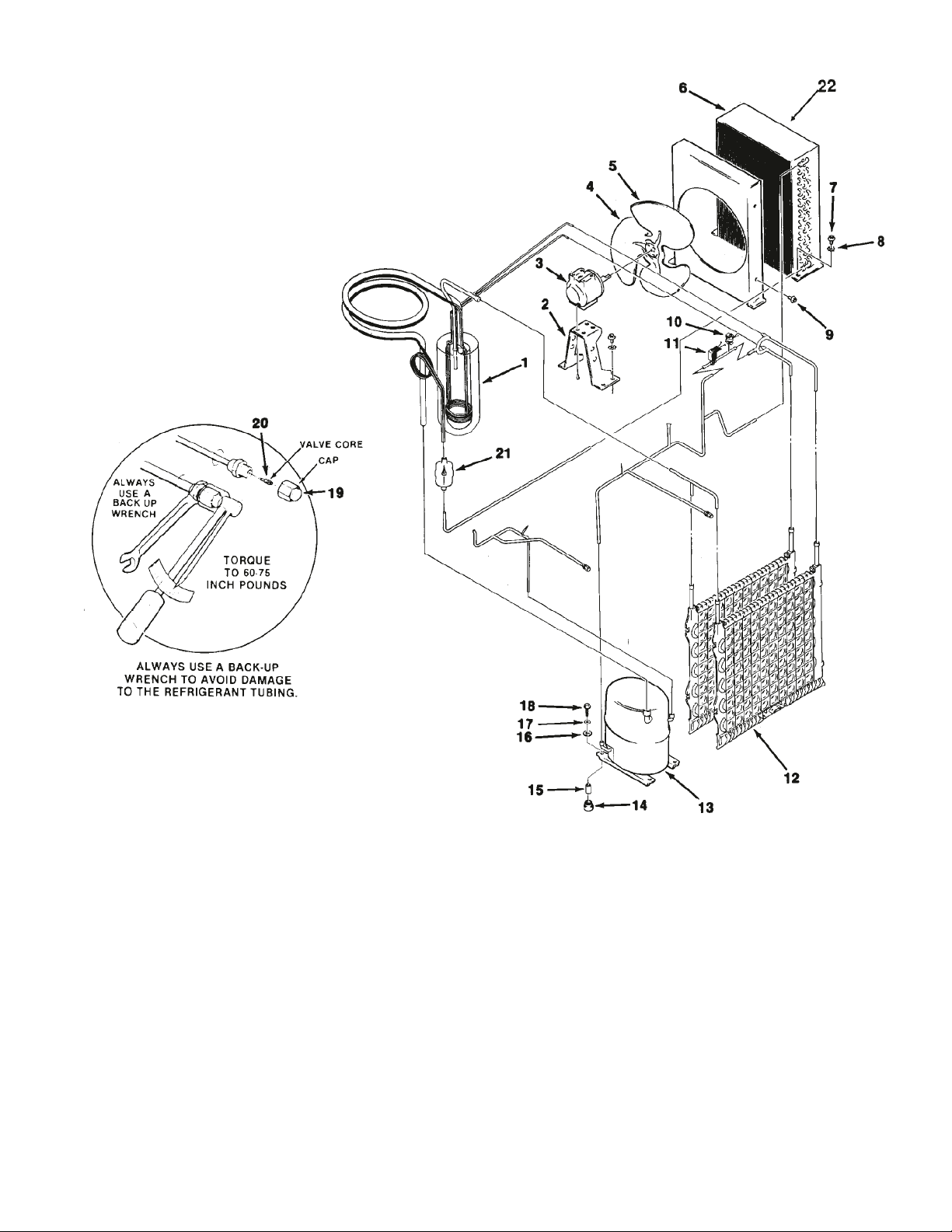
CM500 SERVICE PARTS
AIR COOLED REFRIGERATION
ITEM PART
NUMBER NUMBER DESCRIPTION
1 A31525-020 “C” series heat exchanger
A32245-020 “D” or “E” series heat exh.
2 18-3739-01 Fan Motor Bracket
3 18-5105-11 Fan Motor
4 18-3732-01 Fan Blade
5 02-2558-01 “C” series fan shroud
A32171-001 “D” or “E” series fan shroud
6 18-0398-01 Condenser
7 03-1405-03 “C” series screw
03-1645-01 “D” or “E” series screw
8 03-1410-03 Lockwasher
03-1407-05 Washer
9 03-1531-01 Screw
10 12-2300-03 Hi Temp Cut Out “D” & “E”
11 12-2135-21 Hot Gas Valve
12 À30296-020 Evaporator
November 2003
ITEM PART
NUMBER NUMBER DESCRIPTION
13 18-6100-01 “C” and “D” series compressor
18-6100-50 “C” and “D” series overload
18-8711-20 “E” series compressor (115/60/1)
18-8711-50 “E” series overload)
14 18-6800-01 Grommet
15 18-2300-26 Sleeve
16 03-1407-07 Washer
17 03-1407-07 Washer
18 03-1405-20 Screw
19 16-0563-00 Cap
20 16-0560-00 Core
21 02-3319-02 Drier
22 A32975-001 Foam Filter
Page 4
PDF compression, OCR, web optimization using a watermarked evaluation copy of CVISION PDFCompressor
Page 5
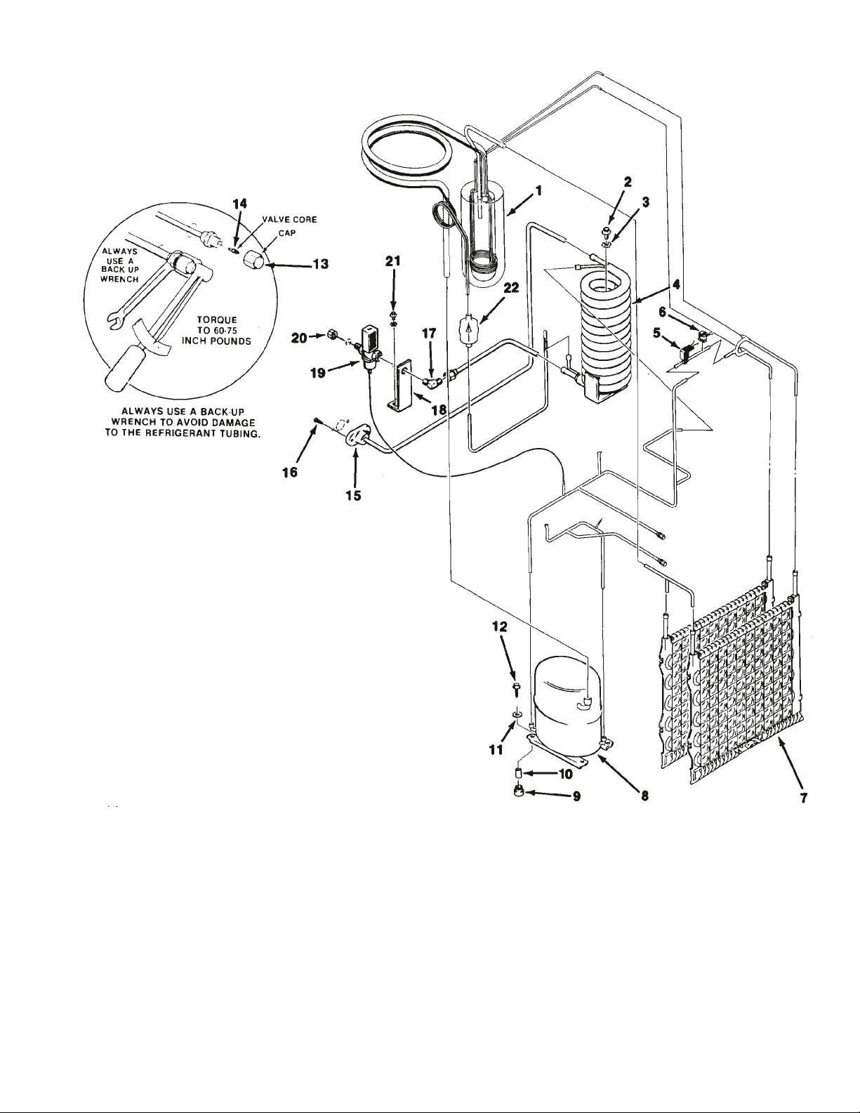
CM500 SERVICE PARTS
WATER COOLED REFRIGERATION
ITEM PART
NUMBER NUMBER DESCRIPTION
1 A31525-020 “C” series heat exchanger
A32245-020 “D” or “E” series heat exch.
2 03-1405-17 “C” series screw
03-1645-01 “D” or “E” series screw
3 03-1407-07 “C” series lockwasher
03-1417-09 “D” or “E” series lockwasher
4 18-3306-25 Condenser
5 12-2135-21 Hot Gas Valve & Coil
6 12-2300-03 Hi Temp. Cut Out (“D” & “E”)
7 A30296-020 Evaporator Plate
8 18-6100-01 “C” and “D” series compressor
18-6100-50 “C” and “D” series overload
18-8711-20 “E” series compressor (115/60/1)
18-8711-50 “E” series overload
9 18-6800-01 Mounting Grommet
10 18-2300-26 Sleeve
11 03-1407-07 Washer
12 03-1405-20 Screw
13 16-0563-00 Valve Cap
14 16-0560-00 Valve Core
15 A33363-001 Drain Fab Assembly
Not Illustrated: Hot Gas Valve Filter, part number
02-3231-02 Use began with “E” series.
ITEM PART
NUMBER NUMBER DESCRIPTION
16 03-1403-14 Screw
17 16-0401-02 Brass Elbow
18 no number Bracket
19 11-0424-01 Water Reg. Valve
20 03-1394-01 Pal Nut
21 03-1403-14 Screw
22 02-3319-02 Filter Drier
November 2003
Page 5
PDF compression, OCR, web optimization using a watermarked evaluation copy of CVISION PDFCompressor
Page 6

CM500 SERVICE PARTS
WATER SYSTEM
ITEM PART
NUMBER NUMBER DESCRIPTION
1 13-0840-01 Manifold Plug
2 A29703-001 Manifold Water Tube
3 02-2527-01 Water Distrib. Tube
4 13-0617-48 O-Ring (2)
5 02-2519-01 Plastic Tee
6 03-1404-10 Screw
7 02-2878-01 Sump End Cover
8 02-2868-01 Drain Trough
9 no number Cube Chute
10 02-2812-02 Sump for “C” series
02-2869-01 Sump for all others
11 A30918-001 Sump Inlet Tube C thru early E
12 03-1531-01 Screw
13 12-2261-04 Solenoid valve “C” series
12-2313-04 Solenoid valve, “D” or
“E ” series.
14 16-0791-01 Half Union
15 16-0162-00 Strainer for D & early E series
16 03-1394-01 Pal Nut
ITEM PART
NUMBER NUMBER DESCRIPTION
17 03-1645-01 Screw
18 A32282-003 Drain Ass.(Air Cooled)
19 12-2265-21 Water Pump Assembly
20 03-1403-17 Screw
21 03-1407-03 Washer
22 03-1408-31 Washer
23 A30914-002 Pump Mounting Bracket
24 03-1417-05 Lockwasher
25 03-1406-05 Nut
26 03-1394-03 Pal Nut
27 03-1408-34 Special Washer
28 02-2642-01 Plate Mount
29 A30296-020 Evaporator
30 13-0674-07 Drain Hose, 8"
31 13-0674-07 Pump Hose, 33"
32 03-0727-09 Thumbscrew
33 03-1417-03 Lockwasher
November 2003
Page 6
PDF compression, OCR, web optimization using a watermarked evaluation copy of CVISION PDFCompressor
Page 7

CM500 SERVICE PARTS
CONTROL BOX
ITEM PART
NUMBER NUMBER DESCRIPTION
1 13-0557-00 Grommet
2 12-1213-10 Snap Bushing
3 03-1417-18 Lockwasher
4 03-1403-02 Screw
5 03-1403-02 Screw
6 03-1417-18 Lockwasher
7 11-0426-22 Fan Control
8 11-0425-21 High Press. Safety -AC
11-0410-22 High Press. Safety -WC
9 A32168-001 Control Box Cover
10 03-1531-01 Screw
11 12-1980-21 Timer & Switch
12 12-1879-02 Relay, 115 V
13 12-1912-01 Circuit Board
14 03-1403-02 Screw
15 03-1403-05 Screw
16 03-1417-03 Lockwasher
17 11-0427-22 Bin Thermostat
18 03-1403-05 Screw
19 03-1417-03 Lockwasher
20 11-0435-21 Cube Size Control
November 2003
ITEM PART
NUMBER NUMBER DESCRIPTION
21 03-1417-16 Lockwasher
22 12-0426-01 Switch
23 12-0426-01 Switch
24 12-1213-17 Snap Bushing
25 13-0557-00 Grommet
26 03-1423-01 Speed Nut
27 18-1903-44 Potential Relay “C” & “D’
18-1903-50 Potential Relay, “E” series
28 03-1403-02 Screw
29 03-1403-15 Screw
30 12-2469-03 Contactor,
31 no number Twin Speed Nut
32 18-2200-39 Start Capacitor Bracket
33 03-1403-15 Screw
34 18-1901-42 Start Capacitor “C” & “D”
18-1901-03 Start capacitor, “E” series
35 18-2200-38 Start Capacitor Cap.
36 18-1902-45 Run Capacitor “E” series only
Page 7
PDF compression, OCR, web optimization using a watermarked evaluation copy of CVISION PDFCompressor
Page 8

June, 1993
Page 8
Use of the High Temperature Cut Out begins with serial number 872530-01G
Wiring Diagram CM500AE-1C (115/60/1) Air - Cooled
CM500 SERVICE PARTS
PDF compression, OCR, web optimization using a watermarked evaluation copy of CVISION PDFCompressor
Page 9

August 1993
Page 9
Use of the High Temperature Cut Out begins with serial number 872530-01G
Wiring Diagram CM500AW-1C (115/60/1) Wat er- Cooled
CM500 SERVICE PARTS
PDF compression, OCR, web optimization using a watermarked evaluation copy of CVISION PDFCompressor
Page 10

June, 1993
Page 10
WiringDiagram CM500AE-1D Air Cooled
CM500 SERVICE PARTS
PDF compression, OCR, web optimization using a watermarked evaluation copy of CVISION PDFCompressor
Page 11

August 1993
Page 11
Wiring Diagram CM500WE-1D Water Cooled
CM500 SERVICE PARTS
PDF compression, OCR, web optimization using a watermarked evaluation copy of CVISION PDFCompressor
Page 12

CM500 SERVICE PARTS
"E" Series Air Cooled Wiring Diagram
June, 1993
Page 12
PDF compression, OCR, web optimization using a watermarked evaluation copy of CVISION PDFCompressor
Page 13

CM500 SERVICE PARTS
"E" Series Air Cooled Wiring Diagram"E" Series Air Cooled Wiring Diagram"E" Series Air Cooled Wiring Diagram
August 1993
Page 13
PDF compression, OCR, web optimization using a watermarked evaluation copy of CVISION PDFCompressor
Page 14

CM500 SERVICE PARTS
"E" Series Water Cooled Wiring Diagram
June, 1993
Page 14
PDF compression, OCR, web optimization using a watermarked evaluation copy of CVISION PDFCompressor
Page 15

CM500 SERVICE PARTS
"E" Series Water Cooled Wiring Diagram
August 1993
Page 15
PDF compression, OCR, web optimization using a watermarked evaluation copy of CVISION PDFCompressor
 Loading...