

Page 1

SCCG50 & SCCP50 Service Parts
This is the illustrated parts list for the SCCG50 and
the SCCP50 Residential Ice Machines
When ordering a service part, always refer to the
complete model number of the equipment being
repaired to be sure of obtaining the correct part.
Many times there are slight differences between
models, and having the complete model number
will aide in selecting the correct part.
Table of Contents
Door ............................................... Page 2
Cabinet ............................................. Page 3
Reservoir and Spray Pump ................................... Page 4
Refrigeration .......................................... Page 5
Under Bin Parts ......................................... Page 6
Control System ......................................... Page 7
Schematic Diagram ....................................... Page 8
Wiring Diagram ......................................... Page 9
June 2008
Page 1
Page 2
SCCG50 & SCCP50 Service Parts
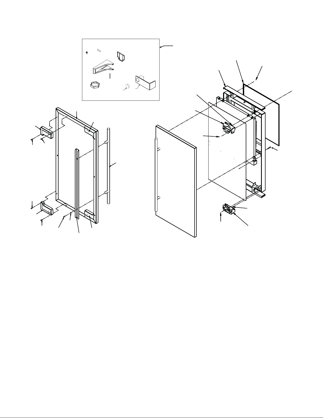
Door
19
16
17
18
11
9
10
1
4
5
5
5
2
7
5
6
2
3
4
8
14
13
13
15
11
12
Items 17 and 18 included with item 19, package
shipped loose in bin.
Item Part
Number Number Description
1 Door panel kits. Kits include
items 1 thru 8.
KDFW White panel, white handle
KDFWS White panel, SS handle
KDFB Black panel, black handle
kDFBS Black panel, SS handle
KDFS SS panel, SS handle
2 02-4433-01 Corner block, RH
3 02-4430-42 Handle, white
02-4430-52 Handle, black
02-4430-01 Handle, SS
4 02-4433-02 Corner block, LH
5 03-1531-01 Screw
6 03-3811-01 Screw
7 03-1410-07 Lockwasher
8 A39390-001 Support bracket
9 13-0949-01 Door gasket
10 03-1404-40 Screw
11 03-3818-01 Screw - hinge to cabinet
12 02-3866-04 Hinge - top right/bottom left
13 03-1404-24 Screw - hinge to door
14 02-3866-03 Hinge
15 03-1403-67 Screw
16 A39513-001 Door assembly, does not
include door panel or hinges
17 02-4429-01 Hinge opening cover
18 02-1875-07 Hole plug for item 17
19 02-4474-01 Hinge package
June 2008
Page 2
Page 3
SCCG50 & SCCP50 Service Parts
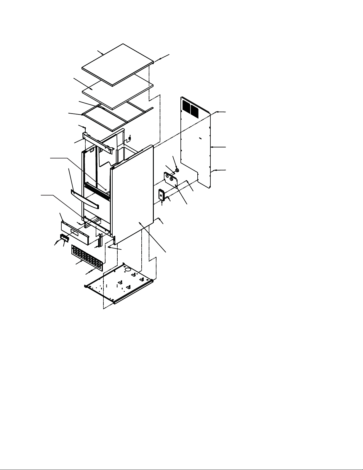
Cabinet
16
15
14
13
12
11
20, 21
10
19
9
1
17
8
6
5
7
1
Item Part
Number Number Description
1 03-1531-01 Screw
2 A39363-001 Back panel
3 A39389-001 Utility routing bracket
4 12-1213-11 Snap bushing
5 A39392-001 Srv panel mntg bracket
6 02-4390-01 Kickplate
7 03-1403-86 Screw
8 02-4441-01 Panel handle
9 A39381-001 Service panel, white
A39381-002 Service panel, black
A39381-003 Service panel, SS
10 02-4392-01 Bin edging
1
1
2
4
1
1
1
1
3
11 A39364-001 Top hinge brkt, RH white
1
A39364-002 Top hinge brkt, RH black
A39364-003 Top hinge brkt, RH SS
A39364-004 Top hinge brkt, LH white
18
A39364-005 Top hinge brkt, LH white
A39364-006 Top hinge brkt, LH SS
12 03-3836-03 Screw
13 02-4438-01 Gasket
14 02-4438-02 Gasket strip
15 02-4426-01 Insulation pad
16 A39362-001 Top panel, white
A39362-002 Top panel, black
A39362-003 Top panel, SS
17 03-1403-86 Screw
18 A39378-001 White cabinet & bin
A39378-002 Black cabinet & bin
A39378-003 SS cabinet & bin
19 A39385-001 Btm hinge brkt, right white
A39385-002 Btm hinge brkt, right black
A39385-003 Btm hinge brkt, right SS
A39385-004 Btm hinge brkt, left white
A39385-005 Btm hinge brkt, left black
A39385-006 Btm hinge brkt, left SS
20 A39379-001 Bin stat bracket/scoop hldr
21 02-4391-03 Scoop
October 2008
Page 3
Page 4

SCCG50 & SCCP50 Service Parts
Reservoir and Spray Pump
15
14
4
20, 21
Rotate item 5 90
degrees & lift to
5
1
3
2
17
18
16
remove.
19
13
12
11
9
6
7
8
Item Part
Number Number Description
1 12-2986-21 Water pump
2 02-4379-01 Pump discharge hose
3 A39030-023 Water probe
4 02-4371-02 Spray platform
5 02-4368-01 Water Tee
6 13-0617-11 O-ring
7 02-4365-01 Front bracket
8 03-3892-01 Thumb screw
9 A39357-001 Curtain
10 02-4383-01 Clamp
11 02-4369-01 Drain cap
12 02-4428-01 Drain tube
13 02-4375-01 Evap bracket, left
10
14 02-4375-02 Evap bracket, right
15 02-4475-01 Grommet
16 02-4381-03 Clip
17 13-0617-04 O-ring
18 02-4381-01 Barbed fitting
19 02-4381-02 Spout
20 02-4373-01 O-ring
21 02-4370-21 Spray nozzle, kit. Set of 3
nozzles, o-rings, screws and nuts.
June 2008
Page 4
Page 5

SCCG50 & SCCP50 Service Parts
Refrigeration
1
4
5
6
7
2
3
10
9
Item Part
Number Number Description
1 A39384-001 Suction line accumulator assy
2 11-0577-01 Thermistor
3 02-4376-01 Evaporator
4 18-8939-21 Compressor
Compressor includes overload, relay and drier
4a 18-8939-51 Overload
4b 18-8939-52 Relay
5 03-3821-01 Clip
6 03-1407-08 Washer
7 18-4700-28 Grommet
8 18-8940-01 Condenser
9 02-4416-01 Drier
10 11-0562-21 Hot gas valve
10a 11-0562-22 HGV coil
8
June 2008
Page 5
Page 6

DRAIN PUMP
MODELS ONLY
GRAVITY DRAIN
MODELS ONLY
14
SCCG50 & SCCP50 Service Parts
Under Bin Parts
15
30
16
17
19
29
20
23
21
27
22
23
24
28
26
25
13
6
7
4
12
8
9
10
11
2
3
1
2
2
5
18
Item Part
Number Number Description
1 12-2990-01 Inlet water sol valve
2 03-1531-01 Screw
3 12-2396-02 Fan motor
4 18-8941-01 Fan blade
5 A39424-001 Fan motor bracket
6 A39359-001 Fan shroud
7 13-0909-01 Gasket, order 1 & cut to fit
8 02-4450-01 Air baffle
9 11-0578-21 Thermostat
10 A39379-001 Thermostat bracket
11 03-1403-16 Screw
12 03-1608-01 Leg leveler
12a 02-4415-01 Leg cap
13 02-1875-18 Hole plug
14 02-2814-13 Hose clamp
15 02-4412-01 Drain hose
16 02-2814-08 Hose clamp
17 16-0671-01 Elbow
18 A39462-021 Pump kit
19 A37334-001 Discharge hose
20 02-0534-02 Hose clamp
21 02-3522-01 Elbow
22 02-3374-01 Check valve
23 02-2814-13 Hose clamp
24 02-4413-01 Drain tube
25 02-3406-01 Barbed connector
26 05-0591-01 Switch hose
27 A39370-001 Switch bracket
28 11-0504-01 Pressure switch
29 03-3904-01 Spring
30 12-2503-21 Pump & motor only
October 2008
Page 6
Page 7

SCCG50 & SCCP50 Service Parts
Control System
1
9
8
7
2
6
5
Item Part
Number Number Description
1 03-3836-03 Screw
2 12-2924-01 Transformer
3 12-2980-01 Bulb
4 02-4380-01 Light cover
5 11-0574-01 Switch panel
6 12-2980-03 Bin light sensor
7 11-0573-22 Controller
8 03-1531-01 Screw
9 02-4386-01 Cover
3
4
Not Shown:
NS1 12-2980-02 Bin light harness & socket
NS2 12-3003-01 Bin stat harness
NS3 12-3000-02 Hi voltage harness, lower
NS4 12-3000-01 Hi voltage harness, upper
NS5 12-2992-01 Water sensor harness
November 2008
Page 7
Page 8

SCCG50 & SCCP50 Service Parts
SWITCHES ON THIS UNIT
SHOWN IN FREEZE CYCLE
WITH DRAIN PUMP IN OPERATION
AND BIN DOOR CLOSED
BIN
LIGHT
BIN
LIGHT
SWITCH
COMPRESSOR
SAFETY
PRESSURE
SWITCH
DRAIN PUMP
PRESSURE
SWITCH
DRAIN
PUMP
HOT GAS
SOLENOID
FAN
MOTOR
L1
N
LINE
12V
TRANSFORMER
WATER
PUMP
WATER
SOLENOID
WATER
CONDUCTIVITY
SENSOR
SUCTION
TEMPERATURE
THERMISTOR
ELECTRONIC CONTROL
BIN
LEVEL
CONTROL
IF DRAIN PUMP
IS INSTALLED
Schematic Diagram
June 2008
Page 8
Page 9

SCCG50 & SCCP50 Service Parts
BIN LIGHT
SWITCH
BIN
LIGHT
W
DRAIN
PUMP
MOTOR
W
BK
R
BK
PUMP
PRESSURE
SWITCH
NO
COMM
NC
R
SAFETY
PRESSURE
SWITCH
NO
COMM
NC
W
PUMP
MOTOR
BU
W
R/W
WATER
SOLENOID
W
BN
FAN
MOTOR
R
HOT GAS
SOLENOID
GN/Y
GN/Y
Y
Y
J2
21
J5
21
GN/Y
EARTH GROUND
V
3
2
1
J1
J4
1
2
345
6
BK
W
O
TRANSFORMER
LOAD
LINE
J9
12
ELECTRONIC
CONTROL
SUCTION
TEMP.
SENSOR
WATER
CONDUCTIVITY
SENSOR
R
R
ONOFF
BIN
LEVEL
CONTROL
32J71
POWER IN
W
BK
GN/Y
W
W
BK
BK/W
1
3
S
M
1
OVERLOAD
RELAY - CURRENT
COMPRESSOR
IF DRAIN PUMP
IS INSTALLED
Wiring Diagram
June 2008
Page 9
 Loading...