

Page 1
Installation and
User's Manual for
Self Contained Cubers
Models CU1526, CU2026 and CU3030
Page 2

Introduction
CU1526, CU2026, CU3030
User Manual
The design of this cuber is the result of years of
experience and testing. Standard features include
a removable bin for service and an on-off switch at
the front of the cabinet for easy operational control.
Keep this manual for future reference.
This installation and user manual is divided into
three main sections: Installation, which provides
the trade person with the information needed to set
up and install this product; Use and Operation,
which provides the user with the information to use
the product; and Maintenance, which provides the
user with the information needed keep it operating
efficiently.
Table of Contents
Installation: Product Specifications ............................... Page 2
Model Number Description ................................... Page 3
Water .............................................. Page 4
CU1526 and CU2026 Cabinet Layout .............................. Page 5
CU3030 Cabinet Layout ..................................... Page 6
Ice Storage Bin Removal .................................... Page 7
Plumbing Requirements ..................................... Page 8
Electrical ............................................. Page 9
Final Check List ......................................... Page 9
Initial Start Up .......................................... Page 10
Adjustments ........................................... Page 11
Use and Operation........................................ Page 12
Control Switches......................................... Page 13
Cleaning, Sanitation and Maintenance ............................. Page 14
What to do before calling for service .............................. Page 16
Note any Caution or Warning symbols when they
appear on the product or in this manual. They
indicate potential hazards.
May 2008
Page 1
Page 3
CU1526, CU2026, CU3030
User Manual
Installation: Product Specifications
Location Limitations:
The product is designed to be installed indoors, in
a controlled environment. Air cooled models
discharge very warm air into the room. Water
cooled models discharge warm water into the
building’s drain. Space needs to be provided for
service access.
Space Limitations
Do not block air flow at the front.
In most cases, CU3030 air cooled models installed
without legs or casters will experience reduced ice
making capacity.
Environmental Limitations
Minimum Maximum
Air temperature 50
Water temperature 40
o
F. 100oF.
o
F. 100oF.
Water pressure 20 psi 80 psi
Note: Ice making capacity will be severely reduced
for air cooled machines in hot environments, such
as those over 95 degrees.
Power supply – acceptable voltage ranges
Minimum Maximum
115 volt model 104 126
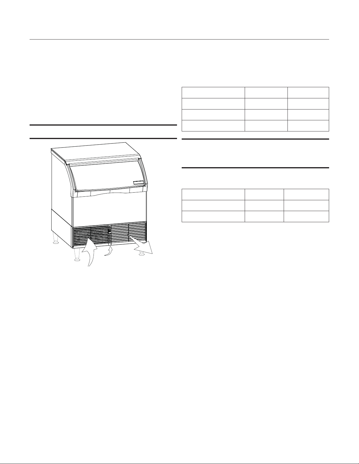
Warm Air Out
Room Temp Air In
Air Flow - Do Not Restrict
Airflow for air cooled models is in the front left and
out the front right; CU3030 air cooled models also
take air in from the bottom of the cabinet
Built In Situations:
•
If built in under the counter with no space
above, the bin cannot be removed without
moving the unit.
•
If built in with 1" or more clearance above the
unit, the bin can be removed without moving
the unit.
•
If built in with between 1/2 and 1 inch of
clearance, releasing the top panel's back flap
prior to placement will allow removal of the
bin without moving the unit.
230 volt model 198 253
Warranty Information
The warranty statement for this product is provided
separately from this manual. Refer to it for
applicable coverage. In general warranty covers
defects in material or workmanship. It does not
cover maintenance, corrections to installations, or
situations when the machine is operated in
circumstances that exceed the limitations printed
above.
Product Information
The product is a self contained cuber with bin. That
type of machine is designed to be free standing or
it can be built in under the counter.
Options
Casters may be used in place of the supplied legs,
the kit number is KBC1.
When not using legs or casters, most codes
require sealing to the floor. Kit numbers to allow
sealing are KPUFM26 and KPUFM30.
May 2008
Page 2
Page 4
Model Number Description
CU1526, CU2026, CU3030
User Manual
Example:
CU2026SA-1A
•
C= cuber
•
U=under the counter type
•
20= nominal ice capacity in 10s of pounds
•
26= nominal width of cabinet
•
S= Cube size. S=small or half dice cube.
•
M=medium or full dice cube
A=Condenser type. A=air cooled. W=water
•
cooled
-1=115 60 Hz, -32 = 230 volt, 60 Hz
•
A=Series revision code. A=first series
•
Note: In some areas of this manual model numbers
may include only the first six characters of the
model number, meaning that the cube size,
condenser type and voltage differences are not
critical to the information listed there.
Product Description & Electrical Requirements
Scotsman ice systems are designed and
manufactured with the highest regard for safety
and performance.
Scotsman assumes no liability of responsibility of
any kind for products manufactured by Scotsman
that have been altered in any way, including the
use of any part and/or other components not
specifically approved by Scotsman.
Scotsman reserves the right to make design
changes and/or improvements at any time.
Specifications and design are subject to change
without notice.
Dimensions
w" x d" x h"**
(without legs)
26.62 x 27.5 x 33
26.62 x 27.5 x 33
30.62 x 30 x 33
Table notes: Height is without legs. Medium cube models have the same electrical characteristics as
Small. Series revision code omitted. * Or HACR type circuit breakers.
** If not using legs, add .25" for screws below base. Legs add 6 to 6.75 inches, but not the 1/4 inch for
the screws. Use of floor mounting kit adds about a half inch.
Model
CU1526SA-1 115/60/1 Air 7.7 15
CU1526SW-1 115/60/1 Water 7.7 15
CU2026SA-1 115/60/1 Air 7.2 15
CU2026SW-1 115/60/1 Water 7.2 15
CU2026SA-32 208-230/60/1 Air 3.7 15
CU2026SW-32 208-230/60/1 Water 2.96 15
CU3030SA-1 115/60/1 Air 10.4 15
CU3030SW-1 115/60/1 Water 10.4 15
CU3030SA-32 208-230/60/1 Air 5.54 15
CU3030SW-32 208-230/60/1 Water 4.48 15
Electrical
volts/Hz/phase
Condenser
Total Load
Amps
Maximum
Fuse Size*
May 2008
Page 3
Page 5

CU1526, CU2026, CU3030
User Manual
Water
The quality of the water supplied to the ice machine
will have an impact on the time between cleanings
and ultimately on the life of the product. Water can
contain impurities either in suspension or in
solution. Suspended solids can be filtered out. In
solution or dissolved solids cannot be filtered, they
must be diluted or treated. Water filters are
recommended to remove suspended solids. Some
filters have treatment in them for suspended solids.
Check with a water treatment service for a
recommendation.
RO water. This machine can be supplied with
Reverse Osmosis water, but the water conductivity
must be no less than 10 microSiemens/cm.
Potential for Airborne Contamination
Installing an ice machine near a source of yeast or
similar material can result in the need for more
frequent sanitation cleanings due to the tendency
of these materials to contaminate the machine.
Most water filters remove chlorine from the water
supply to the machine which contributes to this
situation. Testing has shown that using a filter that
does not remove chlorine, such as the Scotsman
Aqua Patrol, will greatly improve this situation,
while the ice making process itself will remove the
chlorine from the ice, resulting in no taste or odor
impact. Additionally, devices intended to enhance
ice machine sanitation, such as the Scotsman
Aqua Bullet, can be placed in the reservoir to keep
it cleaner between manual cleanings.
Water purge
Cube ice machines use more water than what ends
up in the bin as ice. While most water is used
during ice making, a portion is designed to be
drained out every cycle to reduce the amount of
hard water scale in the machine. That’s known as
water purge, and an effective purge can increase
the time between needed water system cleaning.
In addition, this product has the capability to
automatically vary the amount of water purged
based on the purity of the water supplied to it. The
water purge rate can also be set manually.
Adjustments of purge due to local water conditions
are not covered by warranty.
Uncrate and Set Up
Remove the carton, and using part of the carton as
a cushion, tip the unit on its back to remove the
skid and attach the legs or casters.
If installing the optional kit to attach the unit to the
floor, see that kit's instructions. If placing on the
floor without using that kit, position field supplied
furniture glide pads under the unit to reduce floor
scratches from the metal on the bottom of the unit.
Return the unit to an upright position. Do not start
the unit for at least an hour after it has been
returned to the upright position.
This manual covers several models. The model
number on the product is located in two places, on
the back dataplate and on the model and serial
number tag, located behind the front panel. See the
illustration for the dataplate and serial tag locations.
Write the model and serial number of this product
here:
________________________________________
May 2008
Page 4
Place the ice machine in the selected location and
level it by adjusting the bin leg levelers.
Page 6
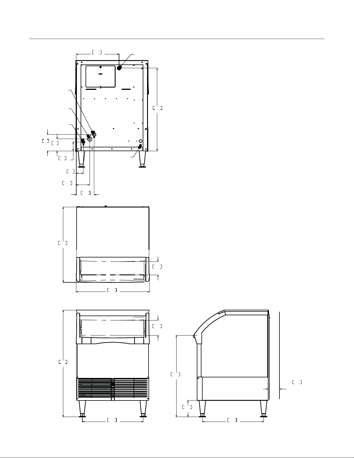
CU1526 and CU2026 Cabinet Layout
5.48
13.9
39.0
99.0
22.12
56.2
4.00
MINIMUM
UTILITY
CLEARANCE
10.2
6.00
15.2
22.25
56.5
29.65
75.3
27.5
69.9
4.86
12.3
26.62
67.6
30.04
76.3
15.55
39.5
2.60
6.6
4.85
12.3
6.50
16.5
3.19
8.1
4.32
11
5.92
15
DRAIN
3/4 FPT
COND WATER
REGULATOR
3/8 NPT
(W/C ONLY)
COND DRAIN
1/2 NPT
(W/C ONLY)
POTABLE
WATER INLET
3/8 FLARE
POWER CORD
CU1526, CU2026, CU3030
User Manual
May 2008
Page 5
Page 7

CU1526, CU2026, CU3030
5.30
13.5
39.0
99.0
25.95
65.9
4.69
11.9
30.0
76.2
30.62
77.8
4.00
MINIMUM
UTILITY
CLEARANCE
10.2
6.00
15.2
24.25
61.6
29.63
75.3
6.99
17.7
3.19
8.1
4.33
11
29.36
74.6
2.77
7
4.65
11.8
6.27
15.9
23.82
60.5
DRAIN
3/4 FPT
COND WATER
REGULATOR
3/8 NPT
(W/C ONLY)
COND DRAIN
1/2 NPT
(W/C ONLY)
POTABLE
WATER INLET
3/8 FLARE
POWER CORD
User Manual
CU3030 Cabinet Layout
May 2008
Page 6
Page 8

Ice Storage Bin Removal
CU1526, CU2026, CU3030
User Manual
The ice storage bin is removable to allow access to
the refrigeration system for service.
1. Remove front louvers. Remove left then right.
2. If the machine is in an ice making mode, push
and release the Manual Harvest button to release
any ice that might be on the evaporator.
3. Push and hold the controller's Off button to shut
the machine off.
4. Remove all ice from the bin.
5. Disconnect electrical power.
6. Remove door (open about 1.5" and pull bottom
out).
7. Remove the top panel, there are two fasteners
under the front corners of the top. Back them out
and lift the top up, push back slightly and lift panel
up and off the machine..
9. Remove two bolts from the bottom of the bin,
one on the left and one on the right.
Remove bolt
to release bin
10. Remove bolt from the back wall of the bin.
Disconnect
hose before
moving bin.
8. Disconnect the drain tube from the bin drain
fitting.
Remove
bolt to
release bin
11. Pull the bin forward and off the chassis.
May 2008
Page 7
Page 9

CU1526, CU2026, CU3030
User Manual
Plumbing Requirements
Connect to cold, potable water. A hand actuated
valve within site of the machine is required. Air
cooled models have a single 3/8” male flare inlet
water connection. Water cooled models have an
additional 3/8” FPT condenser inlet water
connection, and a 1/2" FPT condenser drain.
Water Supply and Filters
If connecting to water filtration, filter only the water
to the reservoir, not to the condenser. Install a new
filter cartridge.
All models require drain tubing to be attached to
them. Air cooled models have a single ¾” FPT
drain fitting in the back of the cabinet. Water cooled
models have the same fitting plus an additional ½”
FPT drain fitting in the back of the cabinet.
Install new tubing when replacing a prior ice
machine, as the tubing will have been sized for the
old model and might not be correct for this one.
1. Connect water supply to water inlet fittings.
3/8" OD tubing is recommended.
2. Connect drain tubing to drain fittings.
3. Route the drain tubing to building drain. Follow
local codes for air gap.
Drain Tubing
Use rigid drain tubes and route them separately –
do not Tee into the bin’s drain and, if water cooled,
do not Tee the condenser drain into the reservoir
or bin drain.
Vent the reservoir drain. A vertical vent at the back
of the drain, extended about 8 - 10" will allow the
gravity drain to empty and also keep any surges
during draining from discharging water out the vent.
Horizontal runs of drain tubing need a ¼” fall per
foot of run for proper draining.
Follow all applicable codes.
Note: This NSF listed model has a 1" anti-back flow
air gap between the float valve orifice and the
highest possible reservoir water level; no back flow
device is required for the potable water inlet.
Water Filter (if used)
Water Inlet
Shut off valve
Drain
Tubing
Floor Drain
Water Cooled
Supply Location
Bin Drain
Connection
Potable
Water
Connection
Water Cooled
Drain Location
Air Cooled Model Plumbing Connections
Water Cooled Plumbing Connections
May 2008
Page 8
Page 10

Electrical
The machine is supplied with a power cord.
208-230 volt, 60 Hz cords have NEMA 6-20P
plugs.
This is a cord-connected unit, and must be on a
separate power supply. Check the dataplate for the
voltage, ampacity and maximum fuse size and per
the dataplate use fuses or HACR circuit breakers.
Follow All Local Codes - This Unit Must Be
Grounded. Do not use extension cords and do not
disable or by-pass ground prong on electrical plug.
Final Check List
CU1526, CU2026, CU3030
User Manual
After connections,
1. Wash out the bin. If desired, the interior of the
bin could be sanitized.
2. Locate the ice scoop (if supplied) and have it
available for use when needed.
Final Check List:
1. Is the unit located indoors in a controlled
environment?
2. Is the unit located where it can receive
adequate cooling air?
3. Has the correct electrical power been supplied
to the machine?
4. Have all the water supply connections been
made?
5. Have all the drain connections been made?
11. Have any water filter cartridges been replaced?
12. Have all required kits and adapters been
properly installed?
6. Has the unit been leveled?
7. Have all unpacking materials and tape been
removed?
8. Is the water pressure adequate?
9. Have the drain connections been checked for
leaks?
10. Has the bin interior been wiped clean or
sanitized?
May 2008
Page 9
Page 11

CU1526, CU2026, CU3030
Manual
Harvest
Clean
Code
Display
Component Operation Indicator Lights
Code Description
.... ......FreezeCycle
flashes....FreezeCycleisPending
.... ......HarvestCycle
flashes....ManualHarvest
.... ......BinisFull
.... ......CleanCycle
.... ......BoardLocked
.... ......TestMode
.... ......Off
.... ......SelfTestFailed
flashes....MaxFreeze-Retrying
..... ......MaxFreezeTimeShutDown
flashes....MaxHarvest-Retrying
.... ......MaxHarvestTimeShutDown
.... ......SlowWaterFill
.... ......HighDischarge Temp
.... ......SumpTempSensorFailure
.... ......DischargeTempSensorFailure
flashes...ShortFreeze-Retrying
Short Freeze - Thin ice
- Unit Remotely
Locked Out - Contact Leasing Company
F
F
H
H
b
C
L
d
O
E
1
1
2
2
3
4
5
7
8
8............
All 4Upper Lights Flashing
Control Operation - See Manual
Water LightOn
De-Scale LightOn
Flush Setting
TestMode
Recall DiagnosticCodes
Reset fromCode 1, 2,4 or 8
- Restore water supply to
machine.
- Clean and sanitize
machine.
- ToChange: Depress Off
for 3 seconds. Press On to select purge
(1-5) setting or Afor Automatic.
- Depress Off for 3 seconds,
then depress Clean for 3 seconds.
- Depress Off
for 3 seconds. Press Harvest repeatedly
to go from most recent to oldest of 10.
- Depress
Off then Depress On.
TechnicianSection
02-4302-01
On Off
Power
Status
De-scaleWater
Sanitize
User Manual
Initial Start Up
1. Remove left front louver. Check machine for
any packing or wires rubbing moving parts.
Note location of control board at the left.
2. Switch the on off
switch to On.
3. Switch on the
electrical power
to the machine.
Observe that
some of the
control’s
indicator lights
glow and its
display shows O.
4. Open the water
supply valve.
5. Push and
release the ON button. The code display will
begin to blink F. Be sure front On/Off switch is
in the ON position.
The purge valve opens and the water pump starts.
In a few seconds the purge valve closes and the
water pump stops. Water will flow into the machine
until the reservoir is full. The hot gas valve and
harvest assist device will activate, then the
compressor and water pump will start. If it’s an air
cooled model the fan(s) motors will begin to turn a
few moments after the compressor starts. The
display will show a continuous F. Five seconds later
the hot gas valve will close and the harvest assist
device will return to its standby position. Warm air
will be discharged from air cooled models.
6. Observe the Ready for Harvest indicator light.
It may blink early in the cycle, that is normal.
The control will ignore that signal for the first 6
minutes of freeze.
7. During the Freeze cycle move the curtain and
observe that the SW1 or SW2 light on the
control board blinks On when the curtain
moves away from the evaporator and Off when
returned to its normal position.
Note: Moving the curtain during the Freeze cycle
has no affect on control function, but will cause
water to flow into the bin.
8. When enough ice has frozen, the Ready for
Harvest indicator light will be on steady. After
May 2008
Page 10
it’s been on steady for a few seconds Harvest
will begin.
The display shows an H. The hot gas valve opens,
the air cooled fan motor(s) shut off and the harvest
assist mechanism is activated. The purge valve
opens to drain some water, when it does the float
valve opens to refill the reservoir. After a few
seconds the purge valve closes but the float valve
continues to fill the reservoir. Harvest continues
until the ice is released as a unit and forces the
curtain to open. When the curtain opens it signals
the controller which returns the unit to a freeze
cycle.
9. Check the ice harvested for proper bridge
thickness. The ice bridge is factory set at 1/8
inch. If needed, adjust bridge thickness. Do
NOT make it too thin.
10. Return the louver to its normal position and
secure it to the machine.
11. Instruct the user in the operation of the
machine and its maintenance requirements.
12. Fill out and mail the warranty registration form.
Write the day, month and year of initial start up
here:
_______________________________________
Typical Ice Making Cycle Times (minutes).
Listed times are for clean machines in proper
installations. Cycle length at startup will be longer
until the system stabilizes.
Model
70
50
o
o
F air /
F. water
90
70
o
o
F. air /
F. water
CU1526A 22-25 36-29
CU1526W 21-24 28-31
CU2026A 15-18 25-28
CU2026W 15-18 20-23
CU3030A 12-15 19-22
CU3030W 10-13 15-18
Page 12

Adjustments
Bridge Thickness - For the Service Tech Only
1. Remove left louver, locate controller on and off
switches.
2. Push and hold Off till the machine stops.
3. Remove curtain.
4. Use a hex wrench and rotate the bridge
thickness adjustment screw in 1/8 turn
increments CW to increase bridge thickness.
Rotate CCW to decrease bridge thickness.
CU1526, CU2026, CU3030
User Manual
1/8-3/16"
bridge
Caution: Do not make the bridge too thin or the
machine will not harvest properly. Bridge thickness
adjustments are not covered by warranty.
5. Return curtain and louver to their normal
positions.
6. Push and release the On button. Check next
harvest of ice. Repeat steps 1-6 if needed.
Water Purge Setting
The water purge is factory set to the automatic
position, suitable for most water conditions. The
setting can be changed to one of 5 manual settings
or left on automatic.
Setting Water Type
1 Minimum - RO water or equivalent
2 Moderate - Low TDS, non RO
3 Standard - for typical water
4 Heavy - High TDS
5 Maximum - Very high TDS
Too Big
Just Right
Too Small
Ice Bridge Thickness Measurement
Adjustment
Screw
Bridge Thickness Adjustment Mechanism
To set purge:
1. Switch the machine OFF by holding the Off
button in until a number or the letter A shows
on the display.
2. Press and release the On button repeatedly
until the number on the display corresponds to
the desired setting.
A Automatic - Factory setting
Note: Water cooled models, the refrigeration
system discharge pressure is factory set at 245
PSIG, which should yield a freeze cycle discharge
water temperature of about 105-110 degrees F.
Adjust if necessary.
May 2008
3. Press and release the Off switch again to
return to the normal control state.
Page 11
Page 13

CU1526, CU2026, CU3030
User Manual
Use and Operation
Once started, the ice machine will automatically
make ice until the curtain is held open by the ice at
the top of the pile. The typical ice level when the
machine is off will be several inches below the door
sill. When ice level drops from use or meltage, the
ice machine will resume making ice. If a small
cluster of ice is holding the curtain open, open the
curtain slightly to release it. The machine should
resume making ice in a few minutes.
Tip: Scoop the ice to the front and back of the bin
to maximize storage.
There are four indicator lights under the bin that
provide information on the condition of the
machine.
Indicator Lights:
Power
•
Status
•
Water
•
De-scale & Sanitize
•
Indicator Lights & Their Meanings
Power Status Water
Steady Green Normal Normal - -
Blinking Green
Yellow -
Blinking
Yellow
Light Off - - - In Cleaning mode
All blinking Unit remotely shut off and locked out - check with leasing company.
Self Test
Failure
-- -
Switching on or off - -
Diagnostic shut down, or, if making
ice, temperature sensor failure
Ice Level When Bin Is Full
De-Scale &
Sanitize
Lack of
water
-
Time to de-scale
and sanitize
If the Water light is on, the machine has sensed a
lack of water. Check the water supply to the
machine. The water could have been shut off or the
water filter cartridges might need to be changed.
If the De-Scale light is on, the machine has
determined that it needs to be cleaned. Contact an
authorized Scotsman service agent and have the
machine cleaned, de-scaled and sanitized.
May 2008
Page 12
Note: A Component Indicator Light switches ON to
indicate that the component is operating.
Note: There are two Curtain Switch lights, SW1 and
SW2. These single plate models have one curtain
switch light on all the time, as a curtain switch light
is ON when a curtain is either open or not present.
Page 14

Control Switches
CU1526, CU2026, CU3030
User Manual
There is a front on and off switch, located in the top
center of the louvers. Switching this switch Off will
immediately stop the machine. Switching it back on
will cause the machine to restart in a timed harvest
cycle. When that cycle is complete, normal ice
making will resume.
The controller (located inside the cabinet) also has
on and off switches, which can also switch the
machine on and off, but their operation is different:
To switch the machine OFF, push and release the
Off button. The machine will shut off at the end of
the next cycle. To shut the machine off
immediately, push and hold the Off button for 3
seconds.
Ice
The cuber drops ice in large sections. That ice will
break up into random parts as it falls into the bin,
but some large sections may remain on top of the
ice in the bin. When removing ice, tap the groups of
ice with an ice scoop to separate them into smaller
units.
Using the ice will help to level it out and allow the
machine to fill it to its maximum level.
Heat
Air cooled models will generate heat when in
operation. That heat is discharged out the front of
the cabinet.
Noise
The ice machine will make noise when it is in ice
making mode. The compressor, fan motor(s) if air
cooled and water pump all produce some sound. It
is also normal to hear some cracking just before
the harvest cycle begins. In addition, during the
harvest cycle the harvest assist solenoid will click
twice as it pushes the ice out and returns to its
normal position. The ice harvests as a unit or slab,
which makes some noise when it impacts the bin.
These noises are all normal for this machine.
To switch the machine ON, push and release the
On button. The machine will go through a start up
process and then resume ice making.
May 2008
Page 13
Page 15

CU1526, CU2026, CU3030
User Manual
Cleaning, Sanitation and Maintenance
This ice system requires three types of maintenance:
Remove the build up of mineral scale from the ice machine’s water system and sensors.
•
Sanitize the ice machine’s water system and the ice storage bin.
•
Clean or replace the air filter and clean the air cooled condenser (air cooled models only).
•
It is the User’s responsibility to keep the ice machine and ice storage bin in a sanitary condition. Without
human intervention, sanitation will not be maintained. Ice machines also require occasional cleaning of
their water systems with a specifically designed chemical. This chemical dissolves mineral build up that
forms during the ice making process.
Sanitize the ice storage bin as frequently as local health codes require, and every time the ice machine
is cleaned and sanitized.
The ice machine’s water system should be cleaned and sanitized a minimum of twice per year.
Note: The front On/Off switch must be in the ON
position during the scale removal and sanitation
process.
1. Remove the left front louvered panel.
2. Remove the top panel.
3. If the machine is operating, push and release
the Harvest button. When the machine
completes the Harvest cycle it will stop. If the
bin is full (b shows in display) push and release
the Off button.
4. Remove all ice from the storage bin
5. Push and release the Clean button. The yellow
Clean light will blink and the display will show
C. The machine will drain the reservoir and refill
it. Go onto the next step when the reservoir has
filled.
Ice machine scale remover
contains acids. Acids can
cause burns.
If concentrated cleaner
comes in contact with skin,
flush with water. If swallowed,
do NOT induce vomiting.
Give large amounts of water
or milk. Call Physician
immediately. Keep out of the
reach of children.
7. Allow the ice machine scale remover to
circulate in the water system for at least 10
minutes.
8. Push and release the Clean button again. The
yellow Clean light will be on continuously and
the machine will drain and refill the reservoir
repeatedly to purge out the ice machine scale
remover and residue.
9. Allow the drain and refill process to continue for
at least 20 minutes.
10. Push and release the Off button. The clean
cycle will stop and the display will show O.
Note: If unit has not been de-scaled for an
extended period of time and significant mineral
scale remains, repeat steps 5-10.
11. Mix a cleaning solution of 1 oz of ice machine
scale remover to 12 ounces of water.
12. Locate curtain, push in on edge of curtain by
pivot pin to release it. Pull curtain out of
machine.
13. Remove water distributor from ice machine.
Inspect distributor for restricted orifice holes.
Be sure all holes are fully open.
Pour 8 ounces of Scotsman Clear 1 ice
6.
machine scale remover into the reservoir.
May 2008
Page 14
Page 16

CU1526, CU2026, CU3030
Inspect Orifice Holes
User Manual
23. Push and release the On button to resume ice
making.
24. Return the top panel and front louvered panel
to their normal position and secure with the
original fasteners.
Air cooled condenser filter
Inspect Water Distributor
14. Locate ice thickness sensor. Squeeze
mounting legs together to release sensor.
Wash the metal surfaces of the sensor and the
adjustment screw with ice machine scale
remover solution. Also wash the water
distributor and curtain with the ice machine
cleaner solution.
15. Locate water sensor. Squeeze catches
together and pull up to remove sensor. Wash
metal surfaces of sensor with ice machine
scale remover solution.
16. Mix a solution of sanitizer.
Note: A possible sanitizing solution may be made
by mixing 1 ounce of liquid household bleach with 2
gallons of warm (95-115
o
F.) potable water.
17. Thoroughly wash all surfaces of the ice
thickness sensor, water level sensor, curtain
inside of the top panel and the water distributor
with the sanitizer solution.
1. Remove left front grill .
2. Wash the dust and grease off the filter.
3. Return it to its original position.
Do not operate the machine without the filter in
place except during cleaning.
Air cooled condenser
If the machine has been operated without a filter
the air cooled condenser fins will need to be
cleaned.
They are located under the fan blades. The
services of a refrigeration technician will be
required to clean the condenser.
Exterior Panels
The front and side panels are durable stainless
steel. Fingerprints, dust and grease will require
cleaning with a good quality stainless steel cleaner.
Water filters
18. Wash all interior surfaces of the freezing
compartment, including storage bin liner with
the sanitizer solution.
19. Return water level sensor, ice thickness
sensor, water distributor and curtain to their
normal positions.
20. Push and hold the clean button to drain the
reservoir. Push and release the clean button
again and when the purge valve indicator light
goes out, immediately pour the remaining
cleaning solution into the reservoir.
21. Circulate the sanitizer solution for 10 minutes,
then push and release the Clean button.
22. Allow the water system to be flushed of
sanitizer for at least 20 minutes, then push and
release the Off button.
May 2008
If the machine has been connected to water filters,
check the cartridges for the date they were
replaced or for the pressure on the gauge. Change
cartridges if they’ve been installed more than 6
months or if the pressure drops too much when the
ice machine fills with water.
Page 15
Page 17

CU1526, CU2026, CU3030
Manual
Harvest
Clean
Code
Display
Component Operation Indicator Lights
Code Description
.... ......FreezeCycle
flashes....FreezeCycleisPending
.... ......HarvestCycle
flashes....Manual Harvest
.... ......BinisFull
.... ......Clean Cycle
.... ......BoardLocked
.... ......TestMode
.... ......Off
.... ......SelfTestFailed
flashes....MaxFreeze-Retrying
..... ......MaxFreezeTimeShutDown
flashes....MaxHarvest-Retrying
.... ......MaxHarvestTimeShutDown
.... ......SlowWaterFill
.... ......High Discharge Temp
.... ......SumpTempSensorFailure
.... ......DischargeTempSensorFailure
flashes...ShortFreeze-Retrying
Short Freeze - Thin ice
- Unit Remotely
Locked Out - Contact Leasing Company
F
F
H
H
b
C
L
d
O
E
1
1
2
2
3
4
5
7
8
8............
All 4 Upper Lights Flashing
Control Operation - See Manual
Water Light On
De-Scale Light On
Flush Setting
Test Mode
Recall Diagnostic Codes
Reset from Code 1, 2, 4 or 8
- Restore water supply to
machine.
- Clean and sanitize
machine.
- To Change: Depress Off
for 3 seconds. Press On to select purge
(1-5) setting or A for Automatic.
- Depress Off for 3 seconds,
then depress Clean for 3 seconds.
- Depress Off
for 3 seconds. Press Harvest repeatedly
to go from most recent to oldest of 10.
- Depress
Off then Depress On.
Technician Section
02-4302-01
On Off
Power
Status
De-scaleWater
Sanitize
User Manual
What to do before calling for service
Reasons the machine might shut itself off:
Lack of water.
•
Freeze cycle takes too long.
•
Harvest cycle takes too long.
•
High discharge temperature.
•
Controller self test failure.
•
Check the following:
1. Has the water supply to the ice machine or
building been shut off? If yes, the ice machine will
automatically restart within 25 minutes after water
begins to flow to it.
2. Has power been shut off to the ice machine? If
yes, the ice machine will automatically restart when
power is restored.
3. Has someone shut the water off to a water
cooled unit? If yes, after the water supply has been
restored the ice machine may need to be manually
reset.
To Manually Reset the machine.
Push and release the Off button.
•
Push and release the On button.
•
To Shut the Machine Off:
Move the On Off switch to the Off position.
or, at the controller
Push and hold the Off button for 3 seconds or until
the machine stops.
4. Is the curtain open because some ice is stuck
under it? If so, remove the ice and the machine
should start in a few minutes.
Note: Curtain can be removed & replaced anytime
the machine is in a standby mode or when it is in a
freeze cycle. However, removal of the curtain
during freeze will result in water flowing into the
bin. Removal of the curtain during harvest
terminates harvest at that point and, if left off, will
result in the machine shutting off.
May 2008
Page 16
Page 18

SCOTSMAN ICE SYSTEMS
775 Corporate Woods Parkway, Vernon Hills, IL 60061
800-533-6006
www.scotsman-ice.com
17-3234-01
 Loading...