

Page 1
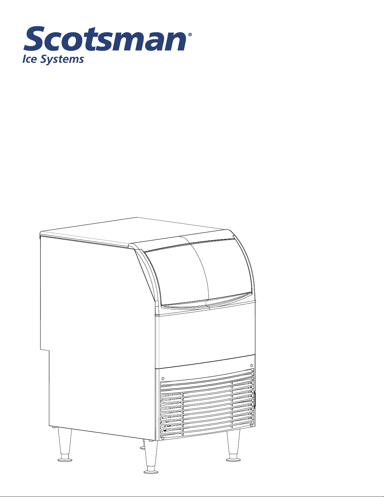
User Manual for
models
UC2024 and UC2724
Page 2
UC2024 and UC2724 User Manual
Introduction
To the owner or user: this manual is intended
to provide you and the maintenance or service
technician with the information needed to install,
startup, clean, maintain and repair this product.
Observe any caution or warning notices. They are
important and provide notice of potential hazards.
Keep this manual for future reference.
If additional technical information is needed, go to
Scotsman’s website, www.scotsman-ice.com.
Note: This is a commercial product. If service is
needed on a unit in a residence, warranty may be
limited. Use a commercial service company. Locate
one from the Scotsman website: www.Scotsman-ice.
com
Scotsman Ice Systems are designed and
manufactured with the highest regard for safety and
performance. They meet or exceed UL563, veried by
a nationally recognized safety authority such as UL or
ETL.
Table of Contents
Specications ............................................................... Page 3
Cabinet Drawing ............................................................. Page 4
Plan and Front Views ......................................................... Page 5
Side and Back Views ......................................................... Page 6
Placement .................................................................. Page 7
Installation .................................................................. Page 8
Initial Start Up ............................................................... Page 9
Use and Operation .......................................................... Page 10
For The Technician: Ice Bridge Thickness Adjustment ............................... Page 11
For The Technician: Indicator Light Reference ..................................... Page 12
Maintenance and Cleaning .................................................... Page 13
Condensers and Air Filter Cleaning .............................................. Page 15
Help ...................................................................... Page 16
Wiring Diagram UC2024 ...................................................... Page 17
Wiring Diagram UC2724 ...................................................... Page 18
Observe the Caution and
WARNING
CAUTION
Warning notices. They are
indicators of important safety
information. Keep this manual
for future reference.
November 2019
Page 2
Page 3
UC2024 and UC2724 User Manual
Specications
This ice maker is designed to be installed indoors,
in a controlled environment. Although it can operate
in a wide range of air and water temperatures, it
will provide the best performance if not subject to
extremes.
Air Temperature Limitations
o
• Maximum: 100
F or 38o C
• Minimum: 50o F or 10o C
Water Temperature Limitations
• Maximum: 100o F or 38o C
• Minimum: 40o F or 4.4o C
Water Pressure, Potable
• Maximum: 80 PSI or 5.5 BAR
• Minimum: 20 PSI or 1.3 BAR
Water Pressure, Condenser inlet
• Maximum: 145 PSI or 10 BAR
• Minimum: 20 PSI or 1.3 BAR; can be as low as
5 PSI or 0.3 BAR if clean and supplied with 45o F
water.
Potable Water Inlet Flow Rate
• 1.25 GPM or 4.7 LPM
Water Cooled Condenser GPM
• 70oF or 21oC water: .25 GPM or .95 LPM
• 50o F or 10oC water: .11 GPM or .41 LPM
Voltage 115 volt models
• Maximum 126 VAC
Operating the machine outside of any of the above
limitations is considered abuse and any resulting
damage is not covered by warranty and could cause a
complete loss of warranty coverage.
Warranty Information
The warranty statement for this product is provided
separately from this manual. Refer to it for applicable
coverage.
In general, warranty covers defects in material
or workmanship. It does not cover maintenance,
corrections to installations, or situations when the
machine is operated in circumstances that exceed the
limitations printed above.
Product Information:
The UC is available in two cube sizes. The ice size
cannot be changed signicantly. The ice is stored
in an insulated bin with ice level automatically
maintained by the control system.
A back ow preventer may be required by local
plumbing codes.
115 volt models include a 5.5 ft. power cord with
NEMA 5-15P plug.
Air cooled models ows in the right front and out the
left front and include a cleanable air lter.
Legs are provided, thread size is 5/8-11. Replacement
leg kit number is KLP7.
Machine may be installed without legs.
For available options and kits, see sales literature.
• Minimum 104 VAC
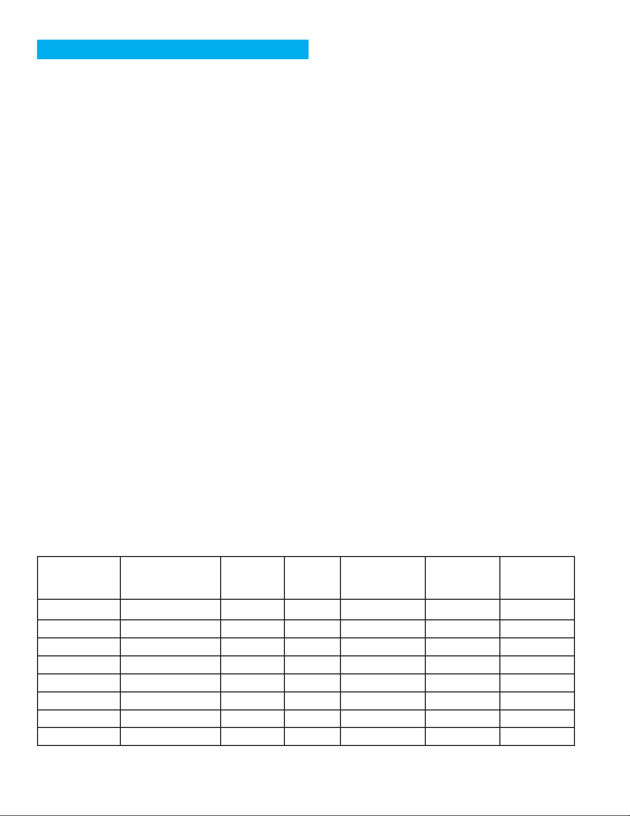
Model
UC2024SA-1A 115/60/1 Air Small 15 5-15P plug 15
UC2024MA-1A 115/60/1 Air Medium 15 5-15P plug 15
UC2024SW-1A 115/60/1 Water Small 15 5-15P plug 12
UC2024MW- 1A 115/60/1 Water Medium 15 5-15P plug 12
UC2724SA-1A 115/60/1 Air Small 15 5-15P plug 14
UC2724MA-1A 115/60/1 Air Medium 15 5-15P plug 14
UC2724SW-1A 115/60/1 Water Small 15 5-15P plug 11
UC2724MW-1A 115/60/1 Water Medium 15 5-15P plug 11
Electrical
Condenser
(Volts/Hz/Phase)
Cube
Size
Maximum Fuse
Size or Breaker
(Amps)
Power Cord
Termination
November 2019
Page 3
Refrigerant
Charge (oz)
(R-134a)
Page 4
UC2024 and UC2724 User Manual
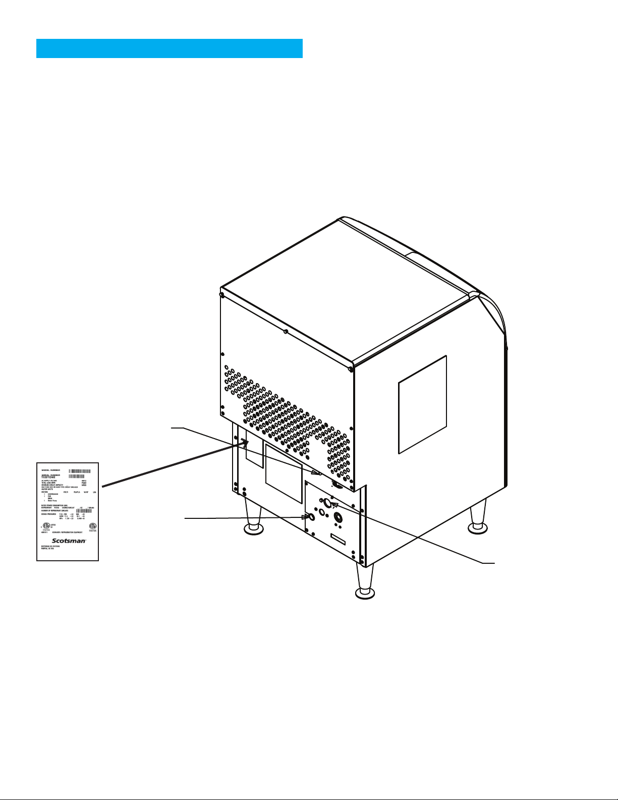
Cabinet Drawing
WATER INLET
Model
and Serial
Number
Dataplate
ACCESS
POWER
CORD
DRAIN
November 2019
Page 4
Page 5
UC2024 and UC2724 User Manual
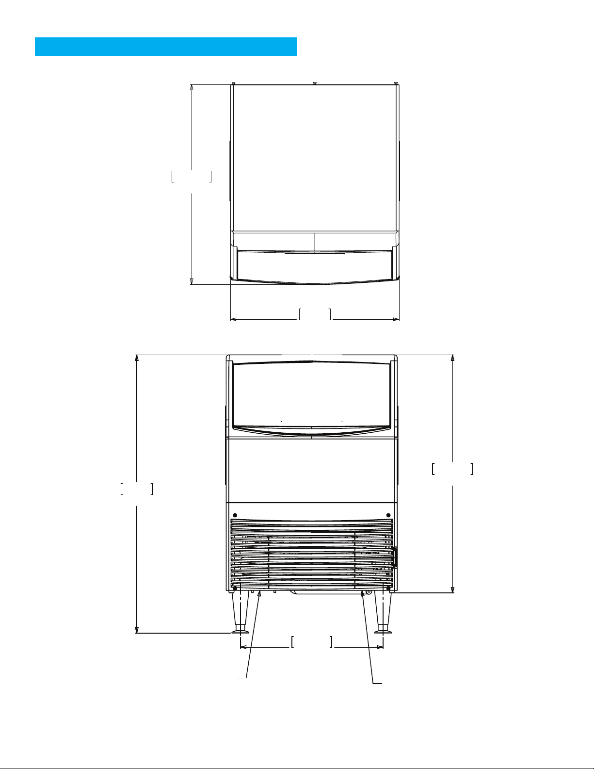
Plan and Front Views
72.3cm
28.4in
99cm
39.0in
61cm
24.0in
84.7cm
33.4in
AIR
EXHAUST
50.8cm
20.0in
AIR
INLET
November 2019
Page 5
Page 6
UC2024 and UC2724 User Manual
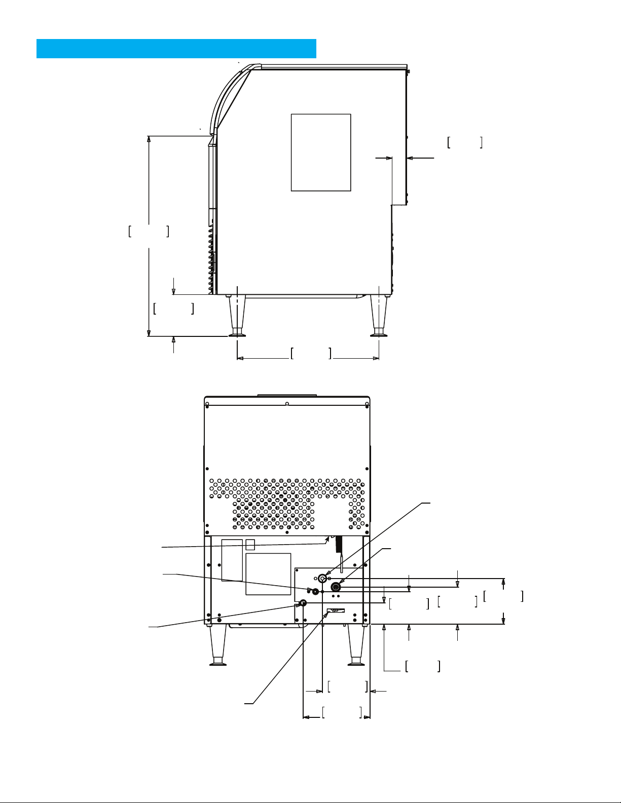
Side and Back Views
72.8cm
28.7in
15.1cm
6.0in
5.3cm
2.08in
UTILITY
CLEARANCE
WATER INLET
3/8” FPT
CONDENSOR
WATER DRAIN
CONNECTION
1/2-14 NPT
POWER
CORD
51.4cm
20.3in
UNIT DRAIN
3/4" FPT
CONDENSER WATER
INLET 3/8-18NPT
11.9cm
4.7in
13.6cm
5.4in
16.8cm
6.6in
WATER REGULATOR
ADJUSTMENT ACCESS
7.8cm
3.1in
17.5cm
6.9in
24.5cm
9.7in
November 2019
Page 6
Page 7
UC2024 and UC2724 User Manual
Placement
The location of the equipment should be selected
with care. Consideration should be given to allow
adequate space for air cooled models to breathe.
The power outlet must be located within the length
of the supplied power cord. If legs will be used, allow
space for the total cabinet height.
The ice machine is not designed for outdoor
use. It must be installed indoors, in a controlled
environment. The air and water temperatures must
not exceed rated limits.
Scotsman assumes no liability or responsibility of
any kind from products manufactured by Scotsman
that have been altered in any way, including the use
of any part and/or other components not specically
approved by Scotsman.
Scotsman reserves the right to make design changes
and/or improvements at any time.
Specications and design are subject to change
without notice.
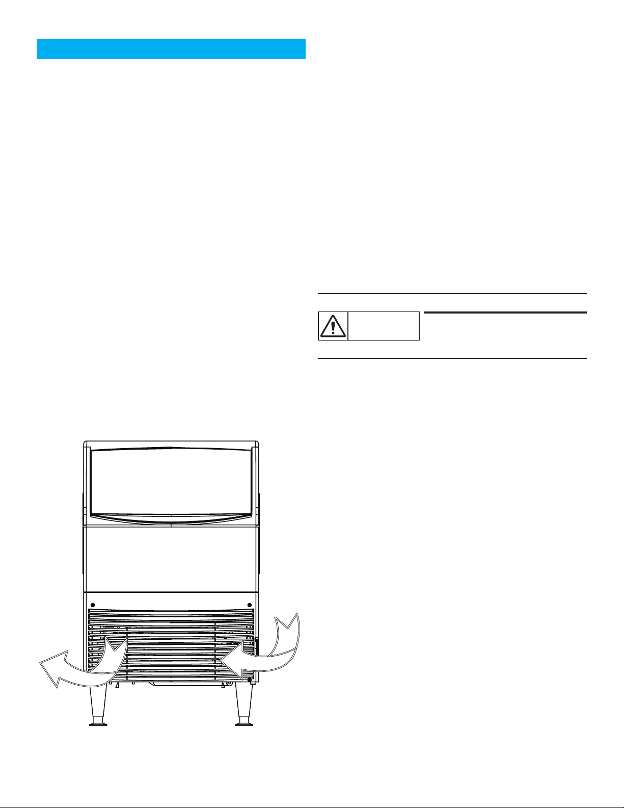
Airow on air cooled models:
• Intake from the right grill
• Exhaust from the left grill
Do not install where this air ow is blocked.
Air cooled models in a small room will require
ventilation to exhaust heat from the condenser. The
condenser fan and motor will generate some noise
while the machine is running. Noise sensitive areas
should consider water cooled equipment or locate
the machine where the noise from ice making will not
objectionable.
Unpack
1. Separate the carton from the shipping pallet
2. Inspect for any hidden shipping damage. If
any is found, retain carton and notify carrier for
potential claim. Shipping damage is not covered
by warranty.
Tip Over hazard.
CAUTION
3. Remove bolts holding machine to pallet.
4. Install the legs. The legs are to be screwed into
the same holes the shipping bolts were removed.
To prevent injury or damage to
the machine please use caution
when lifting the unit.
5. Remove the protective plastic covering the panels.
The longer it is left on the panel, the more dicult
it will be to remove it.
Spacing:
No additional spacing is required at the top or sides.
However, suggested minimum side clearance for the
installation is 1/8’’ or 3.2 mm and suggested minimum
top clearance is 1/4” or 6.4 mm.
The machine may be installed with 0 clearance at the
back. Do not block louvers at the front of the cabinet.
Pre Installation:
Water supplied to the ice machine should be ltered.
Install a lter system that lters out suspended solids.
It may be necessary to add a coarse pre-lter ahead
of the ne lter.
Inspect the place where the ice machine is to be
installed. Check for:
• Space for the cabinet
• Water Supply
• Drain Availability
• Electrical Power Supply
November 2019
Page 7
Page 8
UC2024 and UC2724 User Manual
Installation
Note: The building drain inlet must be lower than
the drain outlets at the back of the ice machine.
The water supply must have a hand shut o valve
accessible when the unit is installed.
For the Plumber
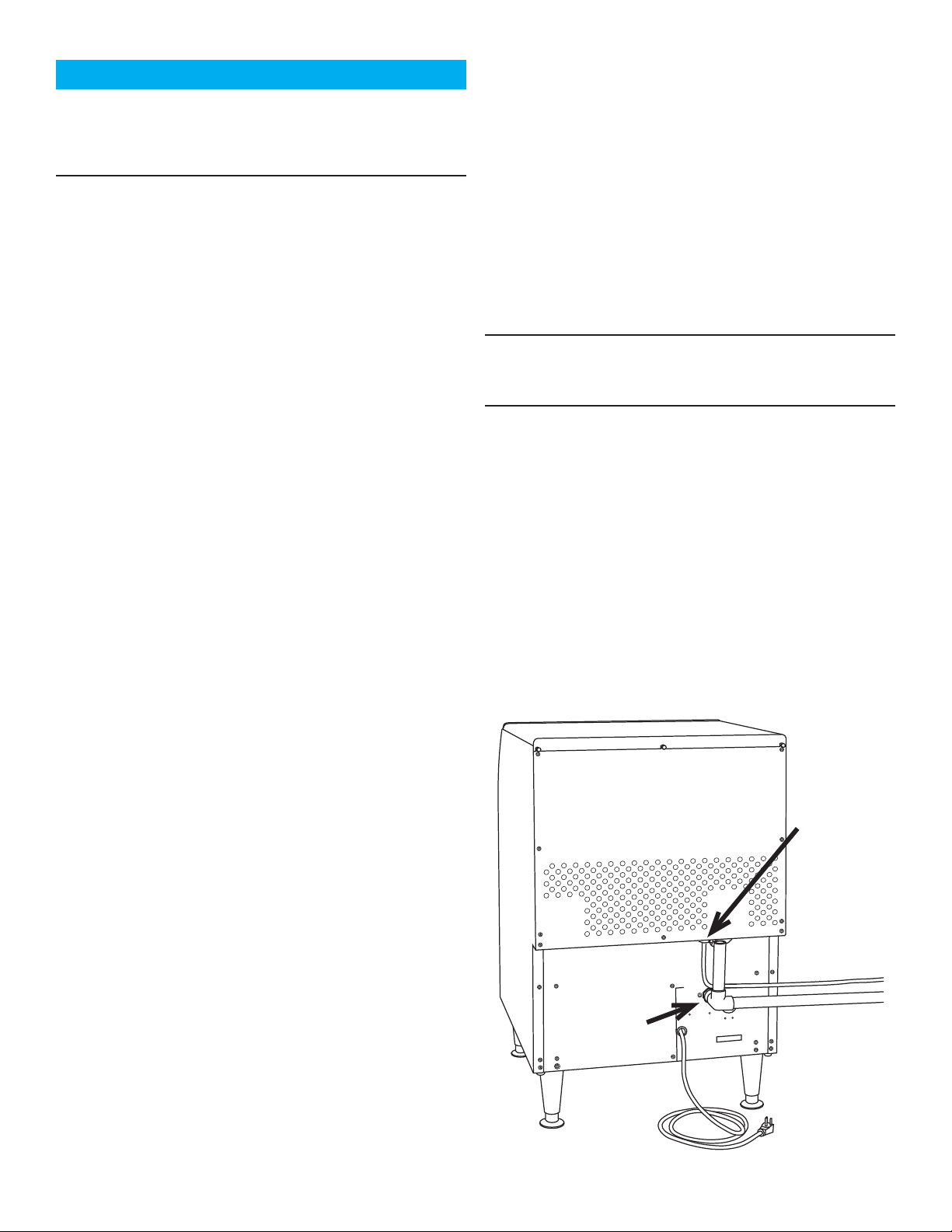
1. Connect cold potable water to the 3/8” FPT inlet
water tting, located below the upper back panel.
A water lter is recommended. Flush the water
line prior to connecting to the ice machine.
A loop of copper tubing may be used between the ice
machine and the water supply. This will allow the ice
machine to be pulled out from its installed location
without disconnecting water. No back ow preventer is
required in the potable water line. This is provided by
the sump inlet, which is above the sump water level
which then cannot be siphoned.
2. Connect a drain tube to the drain tting. Drain
tubes for a water cooled machine should be run
separately. The bin drain tting is 3/4’’ FPT. And it
is plastic. Do not overheat.
• Drain tube material must be rigid and meet
local code.
• Traps in the bin drain line without vents
ahead of them will cause poor draining
• The bin drain must be vented if there is a
long horizontal run 5 feet or more. All drains
are gravity and must have a minimum fall of
1/4’’ per foot of horizontal run.
For the Electrician
This is a cord-connected unit and must be on a
separate single phase power supply. Check the name
plate for the correct voltage. The maximum fuse size
for this circuit should be 15 A, per the nameplate use
fuses or HACR circuit breaker.
Follow all local codes. This unit must be
grounded. Do not use extension cords and
do not disable or bypass the ground pin on
electrical plug.
Note: Electrical outlets can become worn and the
connection can then be erratic. Have it replaced if it is
loose.
After utility connections
1. Level the cabinet, use the leg levelers on the end
of the legs to adjust to cabinet height. Legs should
have been installed when the unit was unpacked.
2. Wash the bin and hood. If desired, the interior of
the bin could be sanitized.
3. Locate the scoop, wash it and have it available for
use when needed.
3. Maintain the air gap required by local code
between the end of the drain to, and the building
drain receptacle.
• Drain tubing should be insulated to prevent
condensation from forming on the tubing.
4. Water cooled models have a separate 3/8” FPT
tting for condenser water inlet. DO NOT FILTER
water to this connection. The condenser drain is
1/2’’ FPT and does not need a vent.
Water Cooled and Recirculating Systems Note
Water cooled equipment may be connected to a
closed loop recirculating system. See the pressure
limits on page 2.
The included water regulating valve will vary the
amount of coolant needed to maintain a constant
discharge pressure. Higher coolant temperatures
will result in increased coolant ow to maintain the
discharge pressure set point.
November 2019
Water Inlet
Fitting, 3/8”
FPT
Drain Fitting
Page 8
Page 9
UC2024 and UC2724 User Manual
Initial Start Up
Final check list:
Ice machine is installed indoors with air
and water temperature controlled within
the limitations detailed in this manual
Ice machine is level in its nal position
Electrical disconnect (switch or plug as
required) is within sight of the installed
machine
Electrical circuit is dedicated to this ice
maker
Voltage has been conrmed within the
specications in this manual and the name
plate on the ice maker
Plumbing connections are complete and
tested for leaks
Ice maker is installed with proper
clearance, allowing for service and utility
connections
Water shut o valve installed near the ice
maker
cycle.
5. Move the On/Wash/O switch to the o position to
switch the machine o. Scoop out any ice in the
bin.
6. Create a solution of sanitizer. Mix 4oz/118ml of
NuCalgon IMS and 2.5gal/9.5L of (900F/320C to
1100F/430C) potable water to create a 200 ppm
solution.
7. Sanitize bin by wiping all surface areas with the
sanitizer solution. Allow to air dry.
8. Move the On/Wash/O switch to ON.
9. Replace louvered panel.
10. Give the owner/user this manual, instruct him/her
in the operation and maintenance requirements
of the unit. Make sure they know who to call for
service.
Fill out the Customer Evaluation and Warranty
Registration form, and mail it in to Scotsman or
register the unit at Scotsman’s website (www.
scotsman-ice.com).
All packing material has been removed.
Start up:
1. Remove louvered front panel.
2. Open the water valve to allow water to the unit.
Check for leaks, if any found correct them.
3. Switch electrical supply on.
4. Move the On/Wash/O rocker switch to On.
The machine will start the ice making process. The
Anti-Slush light will be on, and after a 90 second delay,
water will ow into the sump. The unit starts in a 90
second harvest or defrost mode before switching to the
freeze mode.
Air cooled models will discharge warm air
side of the front panel. Water cooled models will
discharge warm (about 1200F/480C) water out of the
condenser drain.
Freezing will continue until ice has formed adequately,
then the system will switch to a harvest mode and
the ice will release as a group, falling past the ice
sensing plate and into the bin. When ice moves the
ice sensing plate, that triggers the end of the harvest
out the left
November 2019
Page 9
Once started, the ice machine will automatically
make ice until the ice piles up onto the ice sensing
plate, holding it open. The typical ice level when the
machine is o will be several inches below the door.
When ice level drops from use or meltage, the ice
machine will resume making ice.
Tip: To maximize ice storage, scoop the ice to the
sides and front of the bin.
Noise:
This is a commercial ice machine. It contains a
powerful compressor, and, if air cooled, a fan motor. It
will produce some noise when it is making ice. Every
eort was made during its design to minimize the
sound level but some is unavoidable.
Typical Cycle Times (minutes)
Note: First cycle after any restart will be longer than
listed here.
70/50oF. (21/10oC.) 90/70oF. (32/21oC.)
CU2024 16 19
CU2724 12 15
The time to ll a warm storage bin from empty varies by
cabinet temperature and cycle time, but will take about 8
hours.
Page 10
UC2024 and UC2724 User Manual
Use and Operation
To use, simply lift the door by its bottom edge and
slide it up and into the top of the machine. Use the
scoop to remove ice and close the door.
Air cooled models must be able to take in room air
and discharge air heated by the ice making process.
They will make the most ice if there is plenty of room
to breathe.
Blockage of vents or exposure to excessive heat will
reduce the ice making and storage capacity.
The storage bin is insulated but not refrigerated, so
ice will melt during use. That is normal and assures
that fresh ice is available in the bin.
On air cooled models the fan will make some noise
during operation, however rattles and other vibrations
are not normal and should be attended to.
It is normal for the water to occasionally stop owing
over the evaporator (ice making surface) for a few
seconds.
If the machine is in a space colder than the minimums
listed it can become damaged.
Risk of Personal Injury
WARNING
This appliance is not intended for use by persons
(including children) with reduced physical, sensory
or mental capabilities, or lack of experience and
knowledge, unless they have been given supervision
or instruction concerning use of the appliance by a
person responsible for their safety.
Children should be supervised to ensure that they do
not play with the appliance.
CAUTION
The cabinet is not designed to
support anything placed on it.
Do NOT step or stand on it.
The ice making surface can be
damaged by abrasion or by
sharp objects. Do NOT scrub
the ice making surface with
anything.
November 2019
Page 10
Page 11
UC2024 and UC2724 User Manual
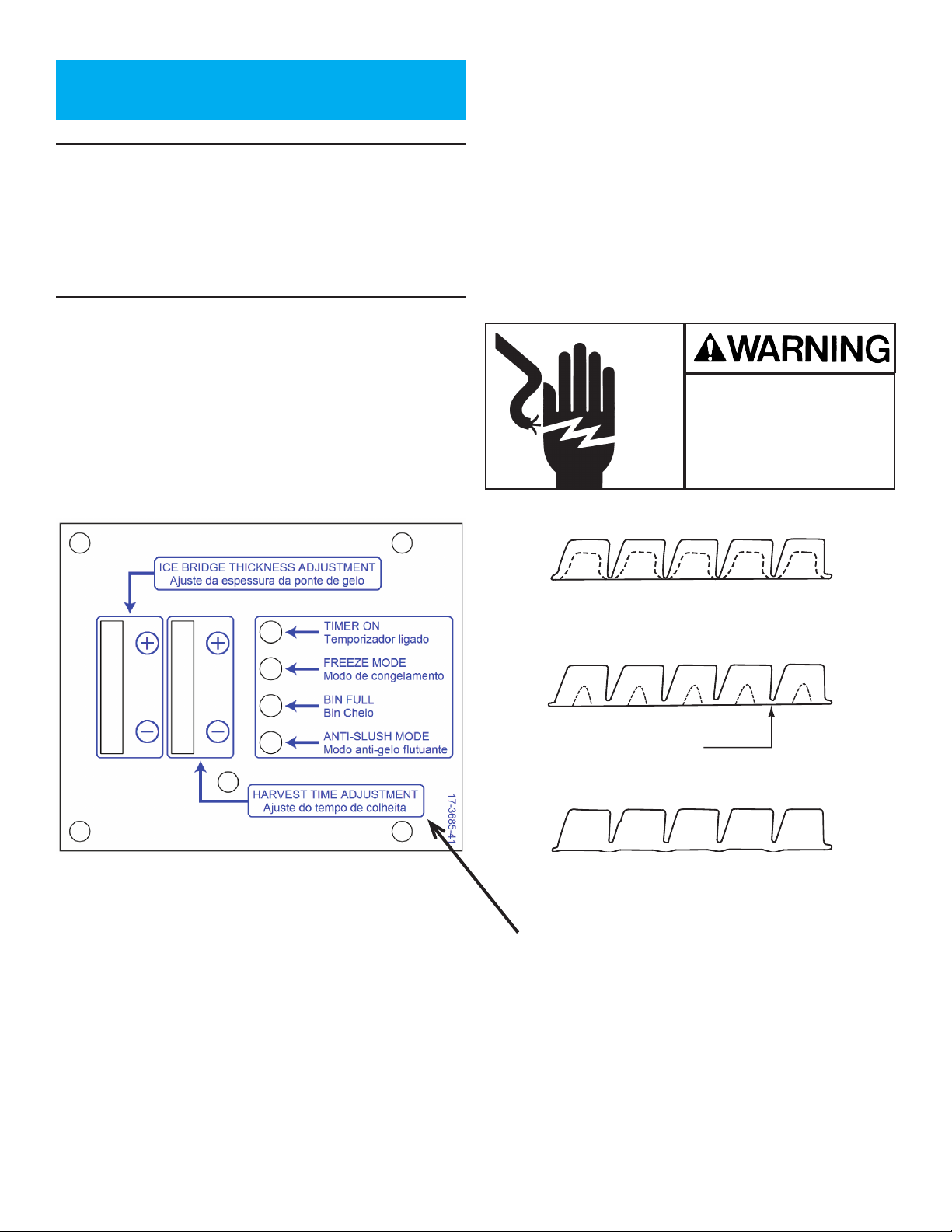
Ice Too Thick
Ice Thickness Diagram
For The Technician: Ice Bridge
Thickness Adjustment
Note: The bridge thickness adjustment is used
to obtain the CORRECT size, not to adjust to
individual preferences. Do NOT make the ice
bridge too thick or too thin, as either will reduce
ice making capacity. Do NOT attempt to adjust the
machine to release individual cubes. There is only
ONE correct size.
Refer to the Ice Thickness Diagram for proper ice
size.
Access the controller by removing the front panel and
pulling out the electrical panel drawer.
Adjust by pushing the + sign or – sign on the ice
bridge adjustment section of the control panel.
Changing bridge thickness should be a one-time
adjustment as the machine will automatically maintain
that ice thickness.
Electrical Shock Hazard
Disconnect electrical
power before beginning
Controller Diagram: Adjustment Indicator Lights
Each push and release of the + or - button will change
the lights that glow or blink indicating a change in ice
size.
Example: pushing + one time changes a blinking light
to steady on type. If the lights are on steady a single
push of + will add one more light to the right and it will
blink.
Ice Too Thin
Ice Just Right
Bridge Thickness
This Section Not Used
There are 10 settings. All 5 lights on steady is
the maximum setting and one blinking light is the
minimum.
November 2019
Page 11
Page 12
UC2024 and UC2724 User Manual
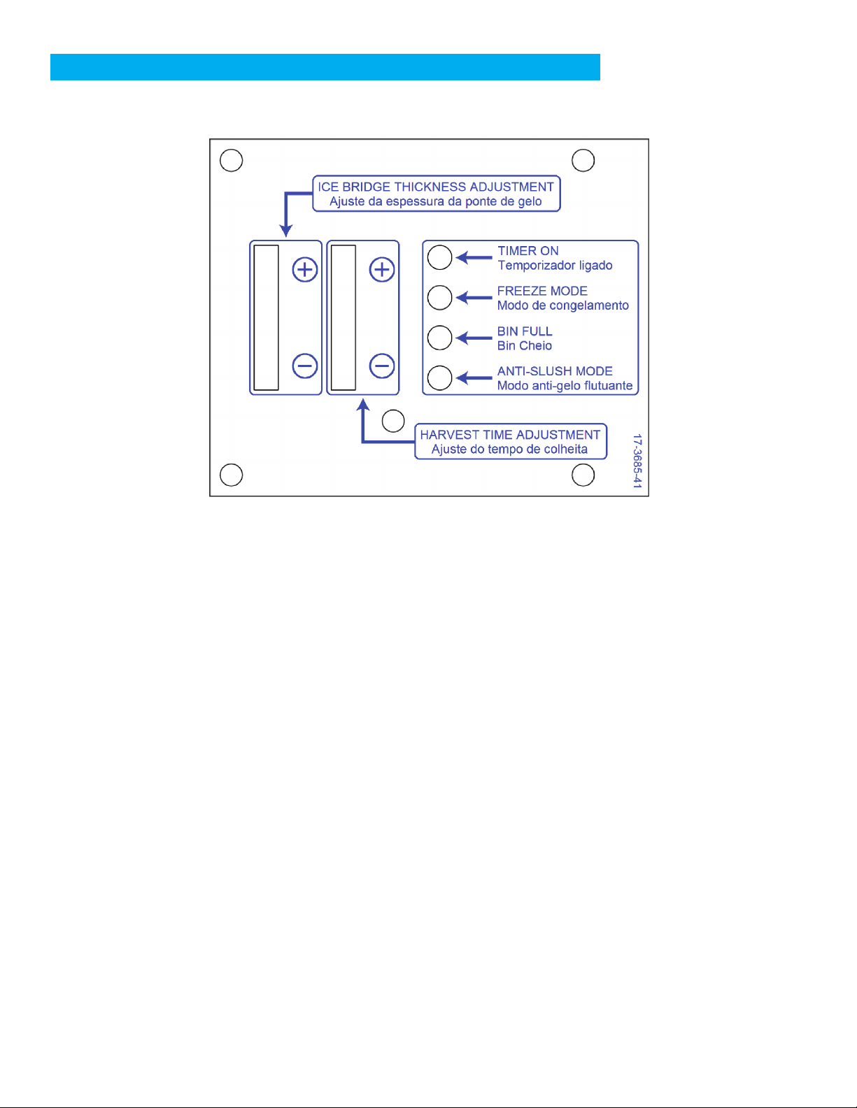
For The Technician: Indicator Light Reference
There are four indicator lights visible when the
electrical component drawer is pulled out.
Timer Cut In
• This light is switched ON when the freeze cycle has progressed signicantly enough for the
evaporator thermostat to have reached its freeze preset temperature. At this point there are only
a few minutes left in the freeze cycle. It is also switched ON when the harvest cycle has been on
and the evaporator thermostat has reached its set defrost temperature.
Curtain Switch
• Normally OFF. This light is switched on and o by the position of the ice sensing plate.
Freeze Cycle.
• Normally ON during a freeze cycle. OFF during harvest or ice release.
Anti Slush
• Normally OFF. This light is switched ON when the pump is stopped during a freeze cycle.
A typical cycle begins when there is no ice on the ice sensing plate (Curtain Switch light OFF). The compressor
and water pump will switch ON and when the discharge pressure increases to the cut in point of the fan
pressure switch the fan motor will begin to rotate the fan. The hot gas and inlet water solenoids are o.
This continues until the evaporator temperature sensor reaches a preset point, which causes the pump to stop
for a few seconds (the Anti Slush light will switch ON). After the Anti Slush light goes out and the water pump
is switched back on, the freeze cycle continues until the evaporator temperature sensor reaches the timer start
point, (Timer Cut In light is switched on).
When the timer has reached the end of its preset freeze time, Harvest begins (the Freeze Cycle light is
switched o). The water pump stops, the hot gas valve and inlet water solenoid valve open and the discharge
pressure falls, so the fan motor stops. Harvest continues until the released ice causes the ice sensing plate to
move and the Curtain Switch light will either: a) blink On and O, if the ice bin is not full, or b) switch On when
the bin is full and ice is on the ice sensing plate.
If the bin is full the machine will shut o and be in a stand by mode. If not full, the cycle will repeat.
November 2019
Page 12
Page 13
UC2024 and UC2724 User Manual
Maintenance and Cleaning
Frequency: Cleaning is recommended about twice a year. The ice machine will not maintain a sanitary
condition without human intervention.
Prep: Obtain food grade scale remover such as Scotsman Clear 1. You will also need a clean container,
sanitizer, clean cloths and clean rubber gloves. Use of a spray bottle is recommended for ease of washing
hard to reach areas.
Note: The ice machine must be connected to water, power and drain during this procedure.
1. Remove the front panel and move the on/o/wash switch to O.
2. Remove the ice from the ice storage bin.
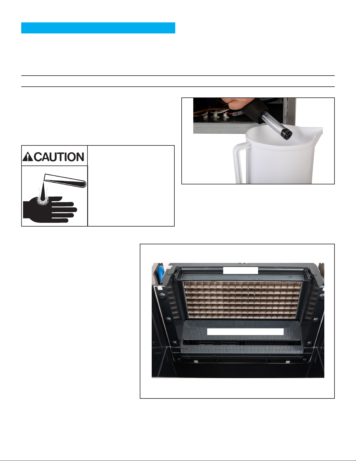
3. Drain the sump water into the container by
removing the plug from the drain hose. The drain
hose is under the control box area. Return the plug
to the drain hose.
Ice machine scale remover
contains acids. Acids can
cause burns.
If concentrated cleaner comes
in contact with skin, ush with
water. If swallowed, do NOT
induce vomiting. Give large
amounts of water or milk. Call
Physician immediately. Keep
out of the reach of children.
4. Put the rubber gloves on.
5. Mix a solution of scale remover and
potable water.
Mix a solution of 5 oz or 150 cc of
Scotsman Clear 1 Scale Remover and
2.5 quarts or 2.4 liters of clean, warm
(95oF/35oC to 115oF./46oC) potable water.
6. Remove the spray bar by unsnapping
it from the left and right ends.
7. Remove the ice level control plate by
unsnapping it.
8. Place both into the scale remover.
Wash them with the clean cloths.
9. Install both the spray bar and ice
level control plate back onto the ice
machine.
10. Pour the scale remover into the
machine’s sump.
11. Put the machine into a wash mode.
Operate it that way for 20 minutes.
Spray Bar
Ice Level Control Plate
12. Stop the wash mode.
November 2019
Page 13
Page 14

UC2024 and UC2724 User Manual
13. Drain the scale remover solution by removing the plug from the drain hose. Return the plug to the drain
hose.
14. Check that the scale has cleared from the spray bar. Remove spray bar if needed to clear any scale, be
sure it is returned to its original position.
15. Mix a second solution of scale remover and lukewarm potable water.
16. Wash the interior of the ice storage bin with the scale remover solution.
17. Pour any remaining scale remover solution into the bin. Be sure it drains away.
18. Mix a solution of sanitizer and lukewarm potable water: Mix 4 oz/118ml of NuCalgon IMS and 2.5 gal/9.5L
of (900F/320C to 1100F/430C ) potable water to create a 200 ppm solution.
19. Pour half of the solution into the sump.
20. Switch the control into a wash mode. Operate it that way for 10 minutes and then switch it to o.
21. Drain the sump by removing the drain plug from the drain hose. Return the drain plug to the drain hose.
22. Wash all interior surfaces of the ice storage bin, including bin door, with the remaining sanitizer solution.
23. Pour a gallon of hot potable water into the bin to clean out the drain.
24. Switch the control to ice making and return the front panel to the unit.
November 2019
Page 14
Page 15
UC2024 and UC2724 User Manual
Condensers and Air Filter Cleaning
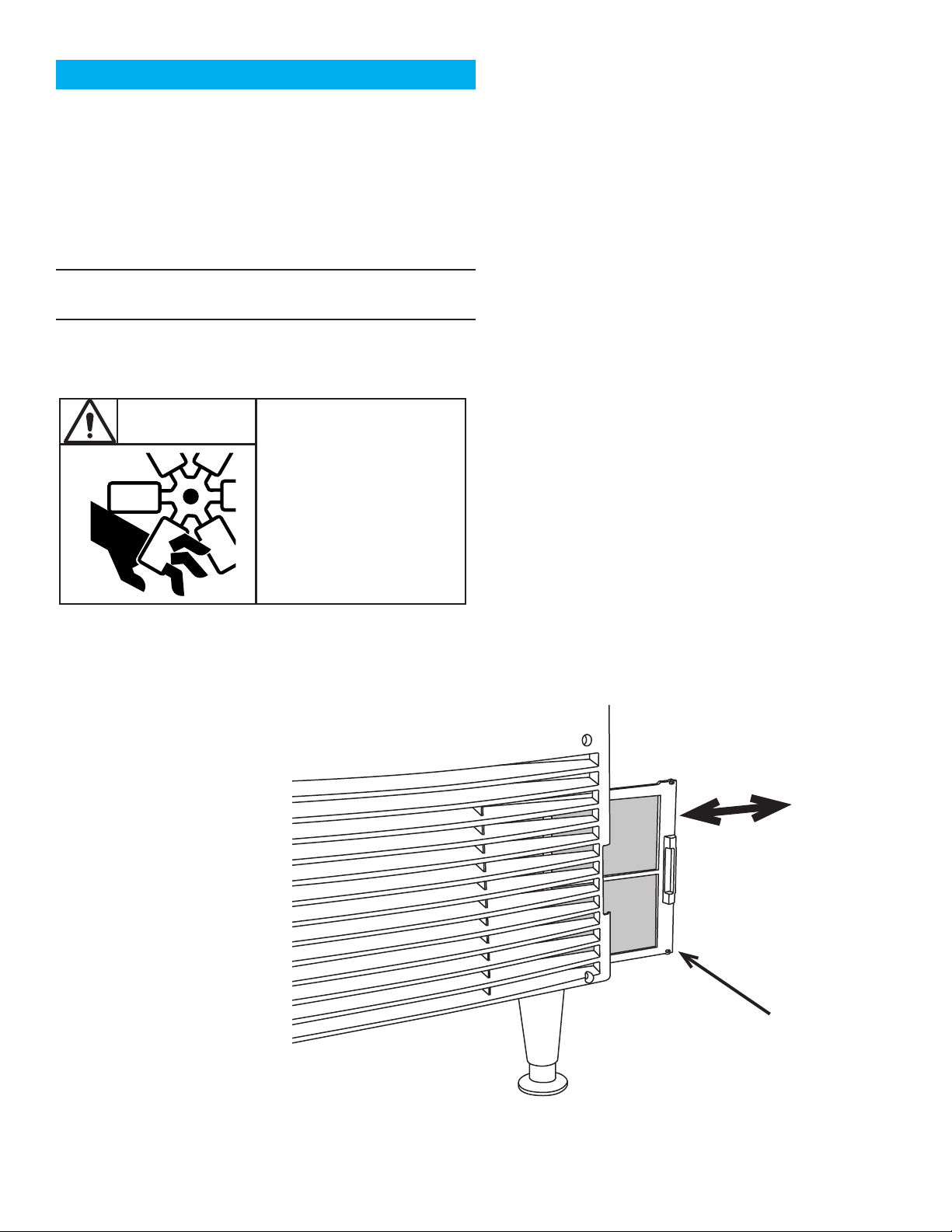
Filters and Air Cooled Condenser
The air lter located on the lower front grill will capture
airborne dust during operation. As the dirt builds up, it
begins to restrict air ow and causes the refrigeration
system to work less eciently. Clean the air lter
regularly.
Remove the lter by sliding it to the right until it is clear
of the ice machine.
Note: It is a snap t and the snaps may be very tight.
Pull hard with two thumbs.
Remove dust and dirt by washing the lter in a utility
sink.
Reinstall lter in the ice machine.
CAUTION
Rotating fan blade can
cause personal injury.
Water cooled equipment may be connected to a
closed loop recirculating system or to a regular water
supply. See the pressure limits on page 2.
The included water regulating valve will vary the
amount of water or coolant needed to maintain
a constant discharge pressure. Higher coolant
temperatures will result in increased coolant ow to
maintain the discharge pressure set point.
That pressure is factory set to 135 PSIG. If needed, it
may be eld adjusted to that set point. An access port
to the adjustment stem is available on the lower back
panel.
In areas with highly mineralized water, the inside
of the condenser may become coated with scale.
When that occurs the amount of water used by the
condenser will increase, as the water regulating valve
opens further to keep the discharge pressure at the
set point.
Unplug unit from power
supply before beginning
to clean condenser
Condenser
The condenser ns require semi annual cleaning. Use
caution to prevent damage to the condenser ns.
Lightly brush dust from the condenser.
Use a vacuum to thoroughly clean the condenser.
Scale on the inside of the condenser may be cleaned
by circulating an acid solution with an auxiliary pump.
Remove and Clean the Air Filter
November 2019
Page 15
Air Filter
Page 16

UC2024 and UC2724 User Manual
Help
Before calling for service, check here for your issue.
Problem: No ice, the machine is silent.
• Be sure the unit is plugged in and that there is power at that outlet. You might temporarily plug the
unit into another, nearby outlet to conrm.
• Be sure the ice level sensor plate is in the make ice position.
• If water cooled, is there water pressure to the unit? If the water has been turned o, the machine
might shut itself o to keep from damaging its refrigeration system. It will automatically restart
after water has been restored and several minutes have passed.
• Remove the front panel and check that the On/O switch is in the On position.
Problem: No ice, the machine is appears to be operating.
• Check that there is water to the machine. Air cooled models will continue to operate without water
but no ice will be made.
• Check for air owing in and out o air cooled models. If none, call for service.
Problem: Ice is either too thick or too thin.
• The ice size may need to be adjusted by a technician. Call for service.
• The ice size sensor may have failed. Call for service.
Winterizing
To prepare a unit for storage, follow these suggestions:
• Clean the unit per the instructions in this manual or those on the unit.
• Discard all ice.
• Drain the unit of all water.
• Disconnect the water supply tubing from the unit.
• Unplug the power cord from the outlet.
• Wipe the cabinet clean.
• Cover the machine to keep dust o the cabinet.
November 2019
Page 16
Page 17
UC2024 and UC2724 User Manual
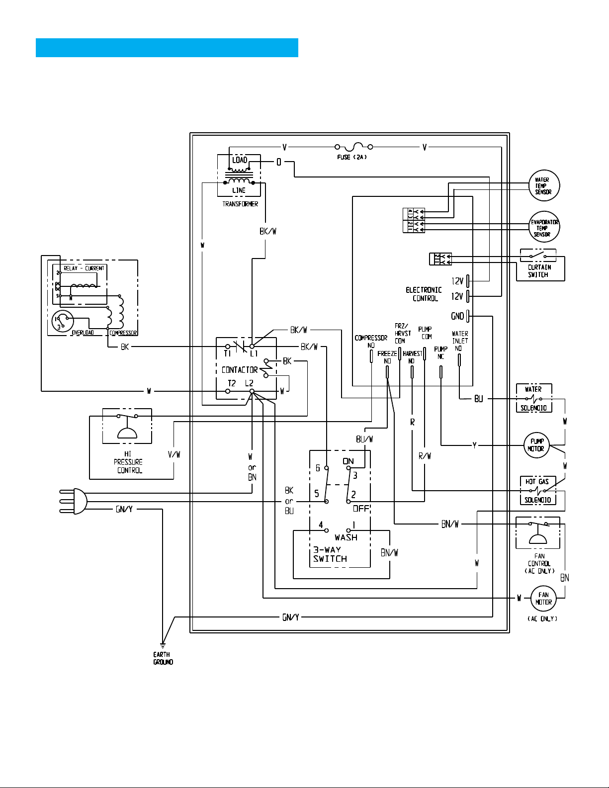
Wiring Diagram UC2024
November 2019
Page 17
Page 18
UC2024 and UC2724 User Manual
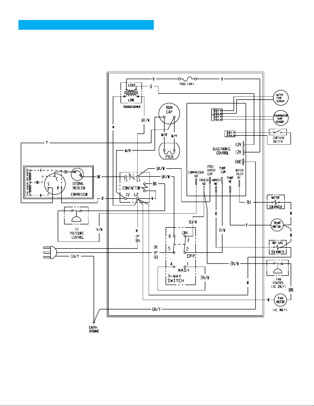
Wiring Diagram UC2724
November 2019
Page 18
Shown in ice making mode
Page 19

SCOTSMAN ICE SYSTEMS
101 Corporate Woods Parkway
Vernon Hills, IL 60061
800-726-8762
www.scotsman-ice.com
17-3672-01 Rev D
 Loading...