

Page 1

NME954R & FME1204R SERVICE PARTS
This parts list contains the service parts and wiring
diagrams for this model. Check the model number
in question to be sure that it is applicable to this
parts list.
TABLE OF CONTENTS
Cabinet . . . . . . . . . . . . . . . . . . . . . . . . . . . . . . . . . . . . . . 2
Refrigeration . . . . . . . . . . . . . . . . . . . . . . . . . . . . . . . . . . . 3
Water . . . . . . . . . . . . . . . . . . . . . . . . . . . . . . . . . . . . . . . 4
Gearmotor . . . . . . . . . . . . . . . . . . . . . . . . . . . . . . . . . . . . 5
NME Evaporator . . . . . . . . . . . . . . . . . . . . . . . . . . . . . . . . . 6
FME Evaporator . . . . . . . . . . . . . . . . . . . . . . . . . . . . . . . . . . 7
Control Box . . . . . . . . . . . . . . . . . . . . . . . . . . . . . . . . . . . . 8
Remote Condenser . . . . . . . . . . . . . . . . . . . . . . . . . . . . . . . . 9
Wiring Diagrams . . . . . . . . . . . . . . . . . . . . . . . . . . . . . . . . . 10
January 2000
Page 1
Page 2
NME954R & FME1204R SERVICE PARTS
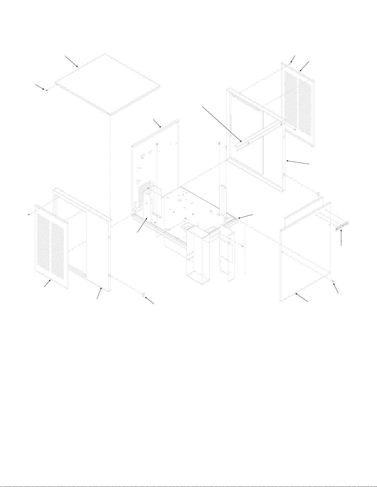
Cabinet Assembly
2
1
11
15
10
7
3
4
12
3
13
ITEM PART
NUMBER NUMBER DESCRIPTION
1 03-1531-01 Screw
2 A33256-002 Top Panel, S.S.
3
A33946-032 Service panel, louvered
4 A33292-002 Right Side Panel, S.S.
5 03-0271-00 Speed Clip
6 15-0808-01 Emblem, gray
7 03-1404-12 Screw
5, 6
14
9
8
ITEM PART
NUMBER NUMBER DESCRIPTION
8 A33255-002 Front panel, louvered
A39048-001 Front panel, non-louvered
9 02-0836-00 Catch
15-0411-00 Strike (on front panel)
10 A35890-001 Base
11 A34348-001 Ft. brace
12 A34039-001 Control Box Support
13 A32435-002 Left Side Panel, S.S.
14 03-1419-22 Screw
15 A35924-002 Rear panel, stainless
May 2005
Page 2
Page 3
NME954R & FME1204R SERVICE PARTS
FLOW
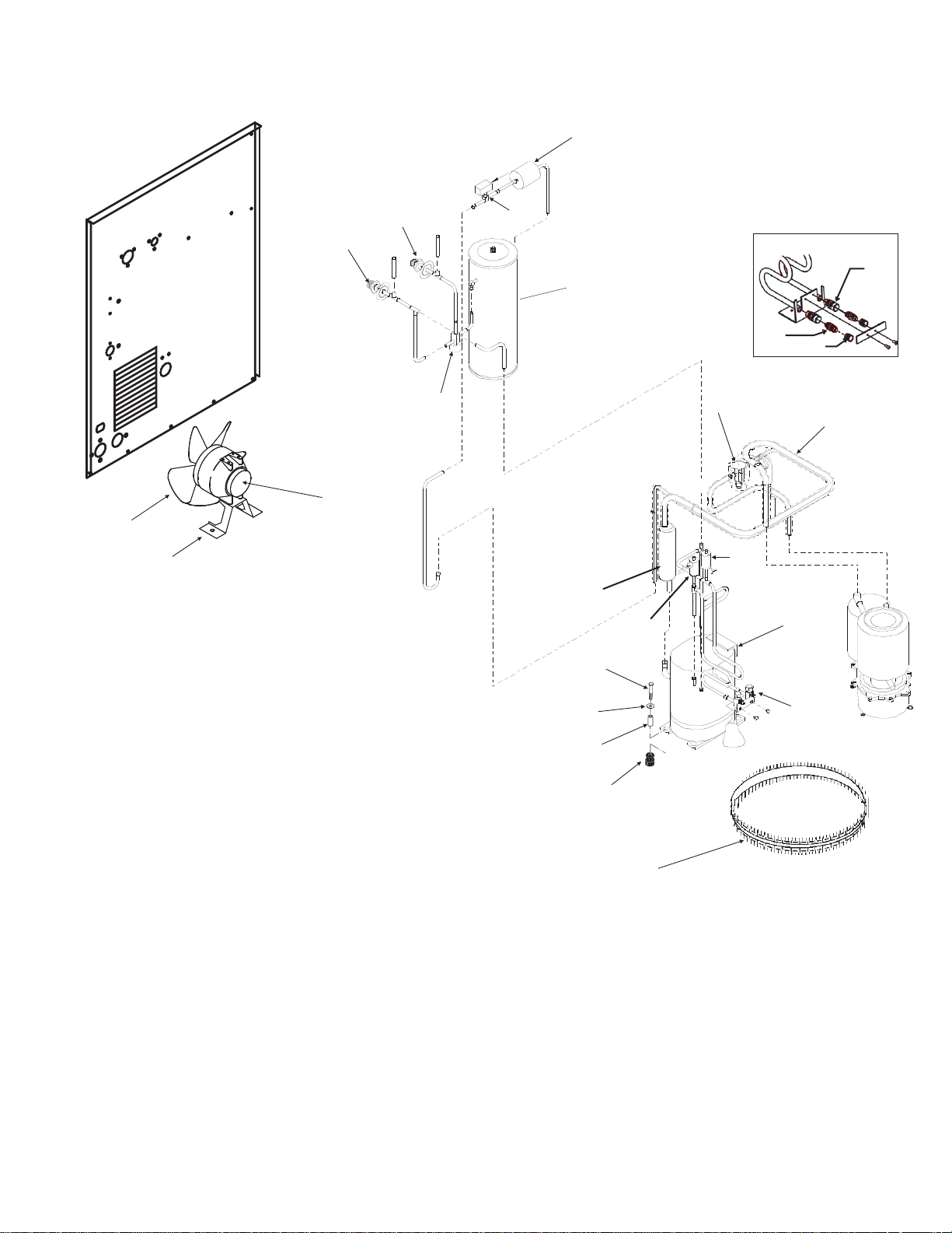
Refrigeration System
9
22
23
14
19
20
21
ITEM PART
NUMBER NUMBER DESCRIPTION
1 12-2135-02 Liquid Line Valve
2 03-1406-13 Nut (for rec. not shown)
3 03-1410-06 Washer (for rec. not shown)
4 A32968-001 Receiver Brace (not shown)
5 A31801-002 Receiver Mount (not shown)
6 16-0761-01 Receiver
7 11-0501-22 Hi Pressure Cut Out
8 03-1645-01 Cap Screw (for rec. not shown)
9 02-3319-02 Dryer
10 03-1405-20 Cap Screw
11 03-1407-07 Washer
12 18-2200-27 Sleeve
13 18-2200-28 Rubber Grommet
14 11-0422-25 Head Pressure Valve
15 11-0488-21 Thermo Expansion Valve
16 A32961-020 Insulation Kit for TXV
17 A36496-001 Suction Line
18 16-0832-20 Access valve
18a 16-0832-02 Stem cap
18b 16-0832-03 Core cap
19 12-1576-02 Fan motor
20 18-8708-01 Fan blade
21 A35246-001 Fan bracket
22 16-0850-03 3/8" Male half
23 16-0850-01 1/2" Male half
1
6
29
30
15,1 6
17
7
From
26
27
10
11
12
13
25
Evap
24
18
ITEM PART
NUMBER NUMBER DESCRIPTION
24 18-8768-22 Compressor 208-230/60/1
Overload for above is internal
18-8768-24 Compressor 200-230/60/3
Overload for above is internal
25 12-1868-03 Crankcase Heater
Note: Compressors include a new HFC dryer.
26. 16-0778-21 Accumulator
27 11-0502-21 Pump down control
28 16-1137-01 Access valve body
29 16-1139-01 Core
30 16-1140-01 cap
28
To Evap
February 2008
Page 3
Page 4
NME954R & FME1204R SERVICE PARTS
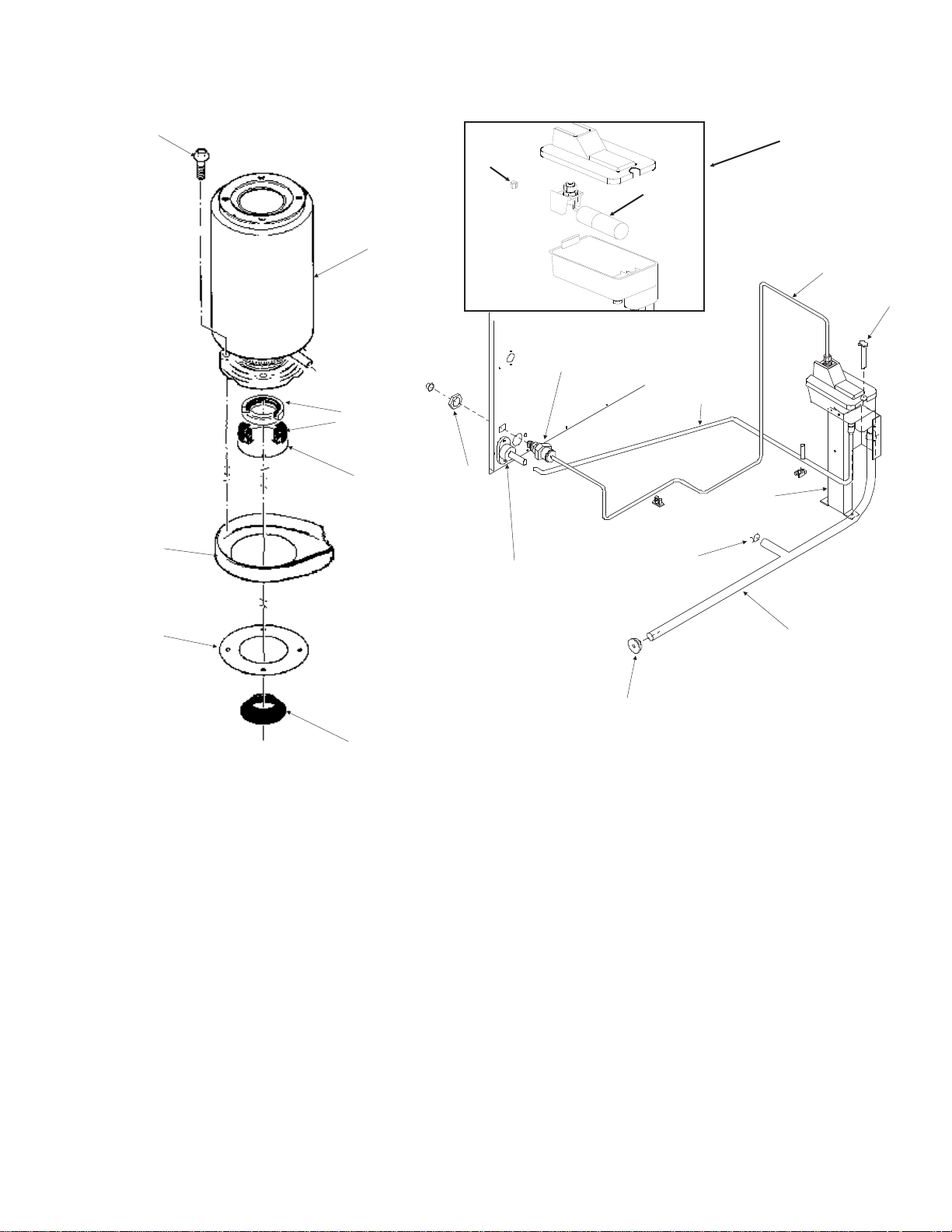
Water System, Water Seal
1
6
5
2
12, 13
19
3
8
9
15
17
18
4
14
7
20
10
11
ITEM PART
NUMBER NUMBER DESCRIPTION
1 03-1405-41 Cap Screw
2 A32890-020 Evaporator
3 02-0929-23 Water Seal
4 02-3266-01 Reservoir & valve
5 02-3266-02 Float valve
6 02-3266-03 Plunger/seat
7 12-2760-21 Water Level Sensor
8 A32777-001 Retaining Ring for Seal
9 02-3837-01 Drip Pan
10 13-0704-00 Gasket
11 02-4663-01 Water Shed
12 16-1039-01 Male connector
13 16-0835-01 Water fitting
14 13-0895-01 Inlet tubing, 4 ft req.
16
21
ITEM PART
NUMBER NUMBER DESCRIPTION
15 03-1394-01 Pal nut
16 A36154-001 Evap. water inlet tube
17 02-1338-00 Hose clamp
18 02-3692-22 Drain fitting
19 02-3826-01 Res. overflow hose
20 A37482-001 Reservoir bracket
21 13-0840-01 Rubber cap
October 2011
Page 4
Page 5
NME954R & FME1204R SERVICE PARTS
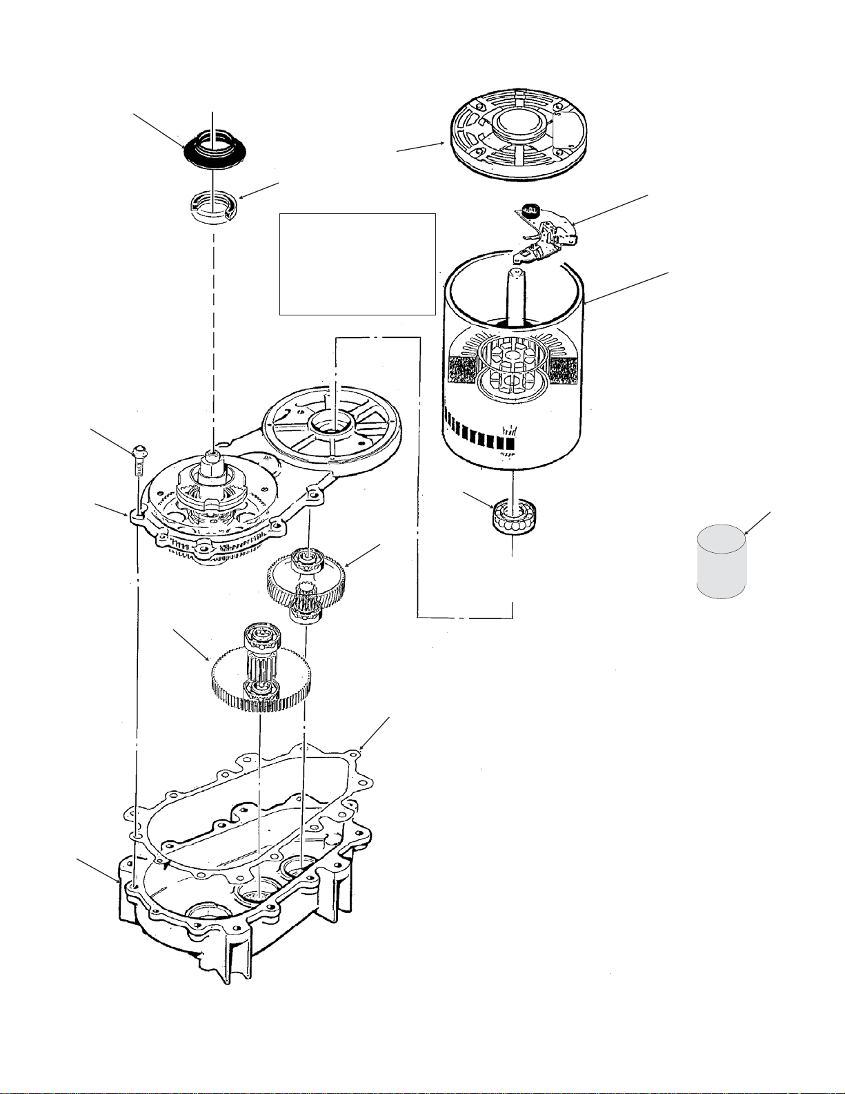
Gearmotor
1
3
2
*NOTE: GEARCASE
COVER INCLUDES
COVER, OUTPUT
SHAFT, KEY, OUTPUT
GEAR, BEARINGS AND
SEAL
4
12
5
6
10
11
13
7
ITEM PART
NUMBER NUMBER DESCRIPTION
1 02-4663-01 Water Shed
2 A32379-029 Seal
8
3 no number End bell
4 A32379-026 Bolt
5 A32379-022 Gearcase Cover*
6 A32379-024 1st Gear and Bearings
7 A32379-023 2nd Gear and Bearings
8 A32379-021 Gasket
9 A32379-020 Gearcase
10 12-2430-24 Start swtich, Emerson
12-2430-44 Start switch, GE split phase
9
11 12-2430-22 Drive Motor
12 12-2430-29 Rotor Bearing, Emerson
12-2430-49 Rotor bearing, GE split
phase
13 A32379-027 Oil, 1 Container
14 A33220-022 Complete Assembly
208-230 volt
Complete assembly includes water shed and drip pan
gasket.
15 A33220-030 Gear case kit, no motor
October 2011
Page 5
Page 6

NME954R & FME1204R SERVICE PARTS
NME Evaporator, Bin Controls
10
11
1
12
3
4
2
6a
5
6
7
14
16
4
13
15
26
18
27
28
19
8
9
ITEM PART
NUMBER NUMBER DESCRIPTION
1. A34969-001 Bail clip
2. 02-3268-01 Drain tube holder
3. 02-2930-04 Ice Chute Cover
4. A32963-001 Insulation Top (half)*
5. 02-3841-01 Ice Chute Body*
6. A33102-001 Insulation Collar Inside*
6a A35419-020 Strap kit*
7. 02-2929-04 Ice Chute Lower
8. A37708-021 Bin Controls Assy.
(set of 2)
9. A32930-001 Chute Gasket
10. 03-1405-52 Hex Cap Screw
11. 02-3001-01 Ice Sweep
12. 13-0871-01 Water Shed
13. 02-2978-01 Lip Seal
14. 02-3128-20 Breaker Cover
15. 13-0617-52 O-Ring
16. 08-0660-01 Auger Stud & washer
21
23
25
20
17
24
8
17. 02-4663-01 Water Shed
18. A34559-020 Bearing
19. 02-2977-01 Lip Seal
20. 13-0704-00 Drip Pan Gasket
21. 13-0617-54 O-Ring
22. 02-3837-01 Drip Pan
23. 13-0617-45 O-Ring
24. 03-1544-08 Soc. Head Screw
25. A32900-020 Breaker
(includes 18 & 19)
26. A38071-022 Auger
27. A32890-020 Evaporator
28. 03-1405-41 Cap Screw
29. 02-4358-01 Insulation
30. 13-0929-02 Insulation donut*
* Insulation changed Oct 2002. Items 4, 6 and 6a
no longer used. Item 5 changed. Item 30 added.
29
22
October 2011
Page 6
Page 7

NME954R & FME1204R SERVICE PARTS
FME Evaporator, Bin Controls
3
1
2
4
17
5
6
7
8
9
ITEM PART
NUMBER NUMBER DESCRIPTION
1. A34969-001 Bail clip
2. 02-3268-01 Drain tube holder
3. 02-2930-04 Ice Chute Cover
4. A32963-001 Insulation Top (half)*
5. 02-3841-01 Ice Chute Body w/ins*
6. A33102-001 Insulation Collar Inside*
7. 02-2929-04 Ice Chute Lower
8. A37708-021 Bin Controls Assy.
(set of 2)
9. A32930-001 Chute Gasket
10. 03-1405-52 Hex Cap Screw
11. 02-3001-01 Ice Sweep
12. 13-0871-01 Water Shed
13. 02-2978-01 Lip Seal
14. 02-3128-20 Breaker Cover
15. 13-0617-54 O-Ring
16. 08-0660-01 Auger Stud
17. A35419-020 Strap kit*
18. A34559-020 Bearing
19. 02-2977-01 Lip Seal
20. 03-1405-27 Screw
21. 13-0617-52 O-Ring
35
11
18
8
19
33
22
10
26
4
14
16
2
12
13
15
20
25
27
28
30
34
21
32
23
22. 02-2916-01 Slotted Collar
23. 13-0617-45 O-Ring
24. 03-1544-08 Soc. Head Screw
25. A34505-020 Breaker (Divider)
(includes 18 & 19)
26. A38071-022 Auger
27. A32890-020 Evaporator
28. 03-1405-21 Cap Screw
29. 02-4358-01 Insulation
30. 02-3837-01 Drip Pan
31. 13-0704-00 Drip Pan Gasket
32. 02-4663-01 Water Shed
33. 13-0617-49 O-Ring
34 03-1408-36 Washer
35. 13-0929-01 Insulation donut*
* Insulation changed Oct. 2000. Items 4, 6 and 17
no longer used. Item 35 added. item 5 changed.
29
31
October 2011
Page 7
Page 8

NME954R & FME1204R SERVICE PARTS
Control Box
5
1
2
3
8
ITEM PART
NUMBER NUMBER DESCRIPTION
1 18-1901-54 Start Capacitor
2. A35971-001 Start Capacitor Bracket
3. A35971-002 Run Cap Bracket
4. 03-1638-03 Screw
5. 18-1902-45 Run Capacitor
6. 12-2469-02 Single Phase Contactor
12-2533-02 Three Phase Contactor
6
4
9
7
10
ITEM PART
NUMBER NUMBER DESCRIPTION
7 12-2835-22 Circuit Board
8. 12-0426-02 Mode Switch
9. 18-1903-33 Potential Relay
10 12-2350-01 Spacer/screw
NOT ILLUSTRATED
11 A37861-001 Control box cover
March 2009
Page 8
Page 9

NME954R & FME1204R SERVICE PARTS
REMOTE CONDENSER
ERC151-32 or ERC302-32
ITEM PART
NUMBER NUMBER DESCRIPTION
1 02-3575-01 Fan guard
2 18-8800-01 Fan blade
3 18-8796-32 Fan motor
January 2000
Page 9
Page 10

17-2683-01
1
POTENT I AL
REL AY
NME954R & FME1204R SERVICE PARTS
Wiring Diagram, 208-230/60/1
1
LIQ LINE
SOL
V
52
BK
BU
BK
PMP D WN
CONTROL
V
BU
Y
RUN
CAP
Y
R
Y
Y
START
CAP
H I PRESS
CON TROL
BK
R
BU
L1L2
T1T2
R
BK
BK
NOTE:
DASHED LINES INDICATE FIELD WIRING
WHICH MUST BE INSTALLED
IN ACCORDANCE WITH THE NATIONAL
ELECTRICAL CODE USING A MINIMUM OF 14 AWG WIRE
BK
EARTH GROUND
BK
BK
C
JUNCTION BOX
SR
SEE NAMEPLATE
FOR SUPPLY VOLTAGE
AND MAX FUSE SIZE
USE COPPER CONDUCTORS O NL Y
T HI S UNI T MUS T BE GROUNDED
MO DE SW ITCH
BU
BU
GN
3
41256
CI RCUI T BO AR D
CO NT ROL B OX
321
6 5 4
9 8 7
BU
BU
R
BK
BK
R
BK
BIN FULL
EEMITT R
(LED)
CONDUCTI VI TY
PR OB E
BIN FULL
DET ECTOR
PHOTOTRANS
BK
BK
BK
R
JU NCTION BOX
FAN
4
START
OL
1
RUN
2
GEAR MOTOR
S-A1
NC
CENTRIFUGAL
SW ITCH
COND
FAN
January 2000
Page 10
Page 11

NME954R & FME1204R SERVICE PARTS
Schematic Diagram, 208-230/60/1
L2
2
MTR
AUG ER DR IVE
PRINTED
CIRCUIT
ASSEMBLY
MODE
SW I TCH
1
PO W E R S U P P L Y
PHOTO TRANS I S TOR
COIL
CONTACTOR
AUGER DRIV E REL AY
L1
CONDUCT IV IT Y PROB E
1R
LED
HPC
LPC
COM
N.O.
T2
SO L
LIQ UID LI N E
CRANKCASE HEATER
MTR
REM CONDFAN
START
CAP
POT
RUN
CAP
RELAY
MTR
FAN
COMPRESSOR
R
MTR
21
ALL CONTROLS SHOW N IN
ICE M AKI N G M O D E
C
S
CO M
N.O.
COM PREL AY
C0I L
POT R ELAY
T1
52
January 2000
Page 11
Page 12

NME954R & FME1204R SERVICE PARTS
Wiring Diagram, 208-230/60/3
BK
17-2679-01
PUM P DW N
CONTRO L
V
GN
BU
BU
MODESWITCH
3
2 1
6
5
4
CIRCUITBOARD
CONTROL BOX
LIQLINE
SOL
Y
BU
Y
Y
V
Y
L3 L2
Y
123
456
789
T3 T2
R
BK
BK
R
BK
HIGH
PR ES S
CONT
BU
L1
T1
BK
BK
BU
BU
BIN FULL
EEMITT R
(LED)
CONDUCTIVI TY
PROB E
BIN FULL
DETECTOR
(PHOTOTRANS)
BK
BK
BK
BK
R
R
JUNCT ION BOX
R
COOLING
FA N
BK
JUNCT I O N BOX
EARTH GROUND
SEE NAMEPLATE
FORSUPPLY VOLTAGE
ANDMAX FUSE SI ZE
T1
T2 T3
R
COMPRESSOR
4
START
OL
1
RUN
2
GEAR MOTOR
S- A1
SEE NA MEPLA TE
FOR SUPPLY VOLTAGE
AND M AX FUSE SI Z E
NC
CENTRIFUGAL
SWITCH
COND
FAN
January 2000
Page 12
Page 13

NME954R & FME1204R SERVICE PARTS
Schematic Diagram, 208-230/60/3
L3
L2
PRINTED
CIRCUIT
ASSEMBLY
MODE
SWITCH
21
MTR
AUGER DRIVE
POWER SUPPLY
CONDUCTIV ITY PROBE
1R
LED
PHOTO TRANSISTOR
COIL
CONTACTOR
COM
GER DRIVE RELAY
AU
L1
HPC
LPC
N. O.
COM
SO L
T3
1
NOTE:
DASHED LINES INDICATE FIELD WIRING
WHICH MUST BE INSTALLED
IN ACCORDANCE WITH THE NATIONAL
ELECTRICAL CODE USING A MINIMUM OF 14 AWG WIRE
T2
CRANKCASE HEATER
REM COND
LIQUID LINE
COOLING FAN
MTR
MTR
MTR
COMPRESSOR
CO MP RELAY
N. O.
T1
January 2000
Page 13
Page 14

Bulletin Number: PS-14-96
Bulletin Date: September 1996
SERVICE BULLETIN
Subject: NME, FME, NSE, NDE and TDE550/650 Top Bearing Lubrication
Two parts have been made available as helpful aids to use when lubricating the top bearing.
02-3559-01
1.
pack the proper lubricant into the top bearing.
2. A36808-001 is a tube of the proper lubricant, also designed to fit a standard grease gun.
Both numbers are in the parts price list.
is a needle that snaps onto a standard grease gun fitting. Use it to insert and deeply
Needle, shown inserted into bearing
 Loading...