

Page 1

INTRODUCTION
NDE750
To the owner or user: The service manual you are
reading is intended to provide you, and the
maintenance or service technician with the
information needed to install, start up, clean,
maintain, and service this ice maker-dispenser.
The NDE750 is a combination nugget ice maker
and countertop dispenser. A water station is
standard.
The NDE750 ice making section is equipped with
the following features: electronic controls for bin
level and low water; thermostatic expansion valve;
front service for most components; and R-404a
(HP62) refrigerant. The ice dispensing section is a
seamless plastic storage bin, with a stainless steel
ice agitator at the bottom to sweep the ice into the
dispensing chute.
Table of Contents
FOR THE INSTALLER: Specifications . . . . . . . . . . . . . . . . . . . . . . . . . . 2
FOR THE INSTALLER . . . . . . . . . . . . . . . . . . . . . . . . . . . . . . . . . . 3
FOR THE PLUMBER . . . . . . . . . . . . . . . . . . . . . . . . . . . . . . . . . . 4
FOR THE ELECTRICIAN . . . . . . . . . . . . . . . . . . . . . . . . . . . . . . . . 5
FOR THE INSTALLER: Final Check List . . . . . . . . . . . . . . . . . . . . . . . . 6
INITIAL START UP . . . . . . . . . . . . . . . . . . . . . . . . . . . . . . . . . . . 7
COMPONENT DESCRIPTION . . . . . . . . . . . . . . . . . . . . . . . . . . . . . 8
COMPONENT DESCRIPTION: Control Box . . . . . . . . . . . . . . . . . . . . . . . 9
ELECTRICAL SEQUENCE . . . . . . . . . . . . . . . . . . . . . . . . . . . . . . . 11
OPERATION: Water . . . . . . . . . . . . . . . . . . . . . . . . . . . . . . . . . . 12
OPERATION: Refrigeration . . . . . . . . . . . . . . . . . . . . . . . . . . . . . . . 13
OPERATION: Ice Vending . . . . . . . . . . . . . . . . . . . . . . . . . . . . . . . . 14
CLEANING and SANITIZING . . . . . . . . . . . . . . . . . . . . . . . . . . . . . . 15
MAINTENANCE AND CLEANING . . . . . . . . . . . . . . . . . . . . . . . . . . . . 16
MAINTENANCE AND CLEANING: Auger . . . . . . . . . . . . . . . . . . . . . . . . 17
SERVICE DIAGNOSIS: Condition - No Ice Being Produced . . . . . . . . . . . . . . 18
SERVICE DIAGNOSIS: Condition - Low Ice Production . . . . . . . . . . . . . . . . 21
SERVICE DIAGNOSIS: Condition - Poor or No Ice Dispensing . . . . . . . . . . . . . 22
REMOVAL AND REPLACEMENT . . . . . . . . . . . . . . . . . . . . . . . . . . . . 23
REMOVAL AND REPLACEMENT: Bearing And Breaker . . . . . . . . . . . . . . . . 24
REMOVAL AND REPLACEMENT: Water Seal . . . . . . . . . . . . . . . . . . . . . 26
TO REMOVE AND REPAIR THE GEARMOTOR ASSEMBLY . . . . . . . . . . . . . 28
REFRIGERATION SERVICE: HP62 . . . . . . . . . . . . . . . . . . . . . . . . . . . 29
REFRIGERATION SERVICE . . . . . . . . . . . . . . . . . . . . . . . . . . . . . . 30
This manual was printed on recycled paper.
Keep it for future reference.
December 1993
Page 1
Note this symbol when it appears.
It marks a possible hazard.
Page 2
NDE750
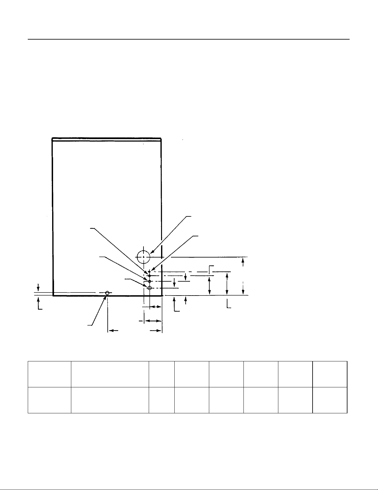
FOR THE INSTALLER: Specifications
This ice maker-dispenser is designed to be
mounted on a machine stand, or a countertop.
Before beginning the installation, check that all the
materials and kits required are available at the
installation location.
Scotsman Ice Systems are designed and
manufactured with the highest regard for safety
and performance. They m eet or exce ed t he
standards of U.L., N.S.F., and C.S.A.
3/8" FPT
Cond.
Water Inlet
(W/C)
1/2" FPT
Cond. Drain
(W/C)
3/4 FPT
Drain
Scotsman assumes no liability or responsibility of
any kind for pr od ucts man uf acture d by S cot s m a n
that have been altered in any way, including the
use of any pa r ts an d/or ot he r co m ponent s not
speci fi cally approved by Scotsman.
Scots m an re ser ves the rig ht to mak e de s ign
chang es and/or im provements at any time .
Specif ications and designs are subject to change
without notice.
BACK VIEW
Water Limitations:
An ice machine is a food
manufacturing plant; it tak es
in a raw material, water, and
turns it into a food product,
ice. Th e purity of the water is
very important in obtaining
pure ice and in maximizi ng
product life.
General recommendations
are:
Electrical Junction
Box
3/8" Flare
Water In let
1. Filter the water used to
produc e ice.
2. Check with a water
treatment specialist for a
water test, and any
recommendations regardin g
6.63"
12.5"
4.63"
filters and trea tment.
.75"
3/4" FPT
Drain
3.84"
2.63"
5.59"
17.59"
7.93"
SPECIFICATIONS
Model
Number
NDE750AE-1
NDE750WE-1
Dimensions
(w/o stand)
H" x W" X D"
45.74" x 35.18" x 29.26"
same
Ice
Type
Nugget
same
Condenser
Type
Air
Water
Refrigerant
Charge
(R-404a)
32 ounces
22 ounces
Basic
Electrical
115/60/1
same
Minimum
Circuit
Ampacity+
18.1
16.5
+ Minimum C i r cui t Am pacit y is us ed to de termi ne wir e si z e and ty p e pe r National El e ctric Code .
Optional kit: KPC750 adds disp ense portion control to units mfg. after 6/97.
May 1997
Page 2
Maximum
Fuse
Size
25
20
Page 3
FOR THE INSTALLER
NDE750
Location
This ice system is designed to be installed indoors,
in a controlled environment.
Minimum Maximum
0
Air Temp 50
Water Temp 40
Water Pressure 20 psi 80 psi
Voltage 104 126
Operating the machine outside of the above
limitations, or outdoors, is potentially damaging to
the machine; also it is misuse of the machine
which may void the warranty.
Service Limitations
Do not install in a location where the top of the
machine is within 6" of a fixed ceiling. Air cooled
models require a minimum of 6 inches to the left
and right of the machine for air circulation. It is
important that the machine be installed in a
location where it has enough space above and
behind it for service.
After uncrating and inspection, the unit is ready for
installation.
Machine Stand Installation
Tip the stand on its back and install the legs, return
the stand to the upright position. Adjust leg
levelers so that the stand does not “rock”.
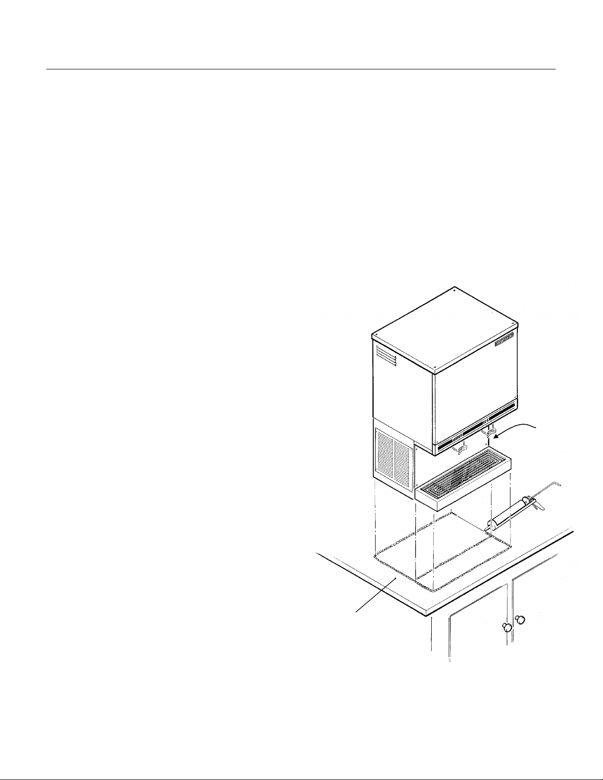
Counter Top or Machine Stand Installation
The base of the icemaker-dispenser must be
sealed to the object it rests upon. Food grade
silastic sealant such as Scotsman part number
19-0529-01 is recommended.
Place a bead of the sealant on the machine stand
or counter top to match the outside edge of the
cabinet base and sink.
The icemaker-dispenser is heavy: use of a
mechanical hoist is recommended to lift it to the
height required to install it.
The DMS machine stand has holes in the top that
match up with threaded holes in the base of the
machine. Secure the machine stand to the base
with 4 5/16" bolts.
F. 1000F.
0
F. 1000F.
In both counter top and machine stand
installations, wipe off and neatly smooth any
excess sealant. Level the machine stand and
cabinet.
Unpack and install the sink brackets. Fit the sink
assembly onto the two sink brackets, and press
onto the bead of sealant. Wipe off and neatly
smooth any excess sealant from under the sink
edge. Connect the sink drain to the dispenser
drain system.
Airflow
SEAL
ICEMAKER-
DISPENSER TO
THE COUNTER
TOP OR
MACHINE STAND
December 1993
Page 3
Page 4
NDE750
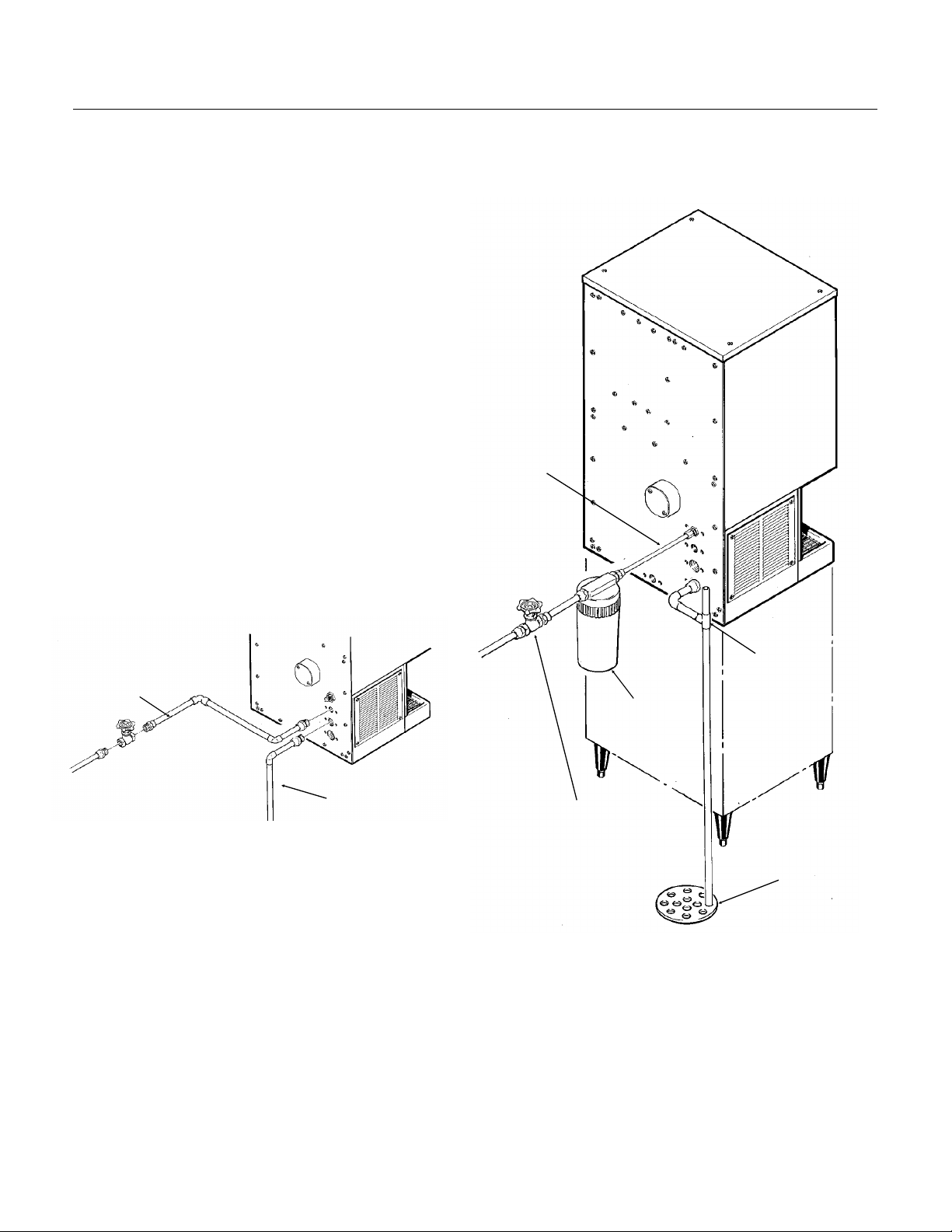
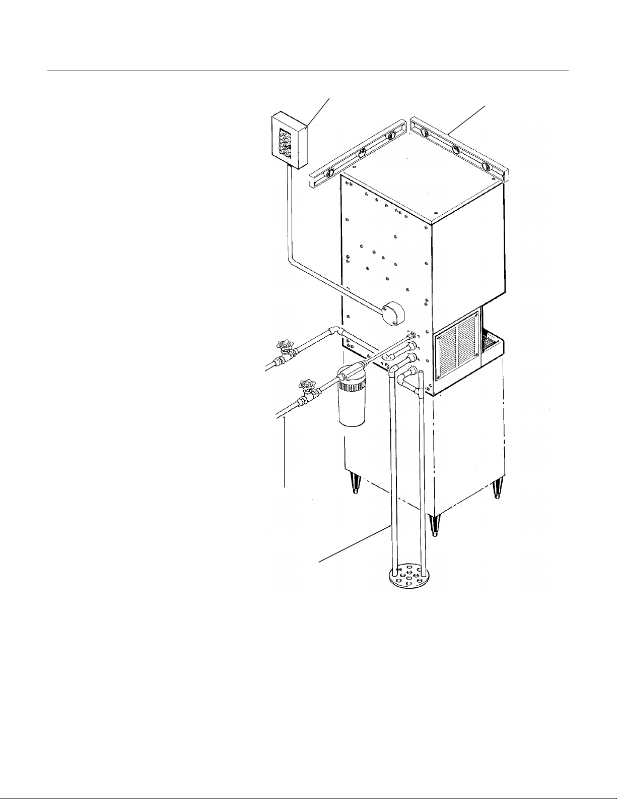
FOR THE PLUMBER
CONFORM TO ALL APPLICABLE CODES
Water Inlet
Air Cooled Models: The recommended water
supply is clean, cold water. Use 3/8" O.D. copper
tubing, connect to the 3/8" male flare at the back
of the cabinet. Install a hand valve near the
machine to control the water supply.
Water Treatment: In most areas, a water filter of
some type will be useful. In areas where the water
is highly concentrated with minerals the water
should be tested by a water treatment specialist,
and the recommendations of the specialist
regarding filtration and/or treatment should be
followed.
Water Cooled Models: A separate 3/8" O.D.
copper line is recommended, with a separate
hand valve to control it. It is connected to a 3/8"
FPT condenser inlet at the back of the cabinet.
The water pressure to all lines must always be
above 20 psig, and below 120 psig.
INLET WATER
Drains
Air Cooled Models: There is one 3/4" FPT drain
WATER COOLED
CONDENSER
WATER INLET
CONDENSER
DRAIN
at the back of the cabinet, the drain line is of the
gravity type, and 1/4 inch per foot fall is an
acceptable pitch for the drain tubing. There
should be a vent at the highest point of the drain
line, and the ideal drain receptacle would be a
trapped and vented floor drain. Use only 3/4" rigid
tubing.
Water Cooled Models: In addition to the above
mentioned drain, a separate condenser drain must
be installed. Connect it to the 1/2" condenser drain
connection at the back of the cabinet.
VENTED
DRAIN
OPTIONAL
WATER
FILTER
SHUT OFF VALVE
FLOOR DRAIN
December 1993
Page 4
Page 5
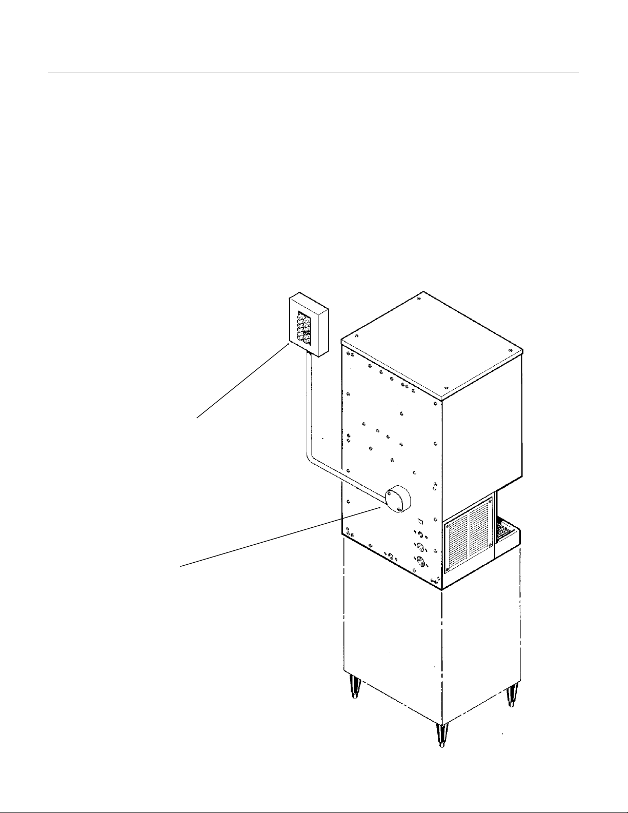
FOR THE ELECTRICIAN
CONFORM TO ALL APPLICABLE CODES
The electrical power to the unit is supplied through
the junction box at the rear of the machine.
Check the nameplate (located on the back panel)
for the voltage requirements, and for the minimum
circuit ampacity. The machine requires a solid
chassis to earth ground wire.
The ice maker should be connected to its own
electrical circuit so it would be individually fused.
Voltage variation must remain within design
limitations, even under starting conditions.
All external wiring must conform to national,
state, and local electrical codes. The use of a
licensed electrician is required to perform the
electrical installation.
NDE750
POWER SUPPLY
ELECTRICAL
CONNECTION
December 1993
Page 5
Page 6
NDE750
FOR THE INSTALLER: Final Check List
1. Is the icemaker-dispenser installed
indoors, in a location where the air and
water temperatures are controlled, and
where they do not go beyond design
limitations?
2. is there an electrical service
disconnect within sight of the installed
machine? Is the machine on a separate
circuit? Has the voltage been checked
and compared to nameplate
requirements?
3. Have all of the plumbing connections
been made and checked for leaks?
4. Has the machine been leveled?
5. Is there a minimum of 6 inches of
clearance at the left and right sides of an
air cooled machine?
ELECTRICAL?
LEVELED?
6. Is there a minimum of 6 inches of
clearance at the top and back of the
machine for service and utility
connections?
7. Is there a water shut off valve
installed near the machine?
8. Have all of the shipping blocks been
removed?
WATER INLET?
DRAINS?
December 1993
Page 6
Page 7

INITIAL START UP
Pre Start Inspection
1. Remove the two front panels.
2. Check that all shipping blocks have been
removed.
3. Remove any and all packing tape (check inside
the storage bin).
4. Inspect the interior of the machine for loose
screws or wires. Check that no refrigerant lines are
rubbing each other. Check that the fan blade on air
cooled models turns freely.
5. Check that the machine is installed correctly
according to the final check list.
Start Up
1. Go through the pre start inspection.
2. Open the water hand valve, observe that water
enters the water reservoir, fills the tube from the
reservoir to the evaporator and then shuts off.
Check for leaks.
NDE750
7. Check ice dispensing by pushing in on the glass
filler lever. Ice dispenses are portion controlled; by
turning a knob, the length of time the unit
dispenses when the glass filler lever is pushed
(and the amount of ice dispensed) is adjusted.
3. Switch the master switch on. The electrical start
up sequence is now on automatic:
A. There will be a short (15 second) delay before
the gearmotor starts.
B. After the gearmotor starts, the compressor will
start.
4. On air cooled models, warm air will begin to flow
from the condenser. Water cooled models will
begin to discharge warm water down the drain.
5. The unit should soon be making ice. If desired,
the low side pressure may be checked: it should
be 38 PSIG + or - 4 PSIG.
The air cooled discharge pressure will depend
upon air and water temperatures, but should be
between 200 PSIG and 300 PSIG.
Water cooled discharge pressure should be about
245 PSIG. If needed, adjust the water regulating
valve.
The above numbers are for new, clean machines.
Field values may be somewhat higher or lower.
6. There are no adjustments to make, so replace
the panels.
8. Switch off the icemaker-dispenser, remove the
top panel and the top of the ice storage bin.
Sanitize the interior of the ice storage bin by wiping
it with a mixture of 1 ounce of household bleach to
2 gallons of water, allow to air dry. Replace all
covers and panels. Switch the icemaker-dispenser
back on.
9. Give the owner/user the service manual, instruct
him/her in the operation and maintenance
requirements of the unit. Make sure they know
who to call for service.
10. Fill out the Customer Evaluation and warranty
Registration form, and mail it in to Scotsman.
December 1993
Page 7
Page 8
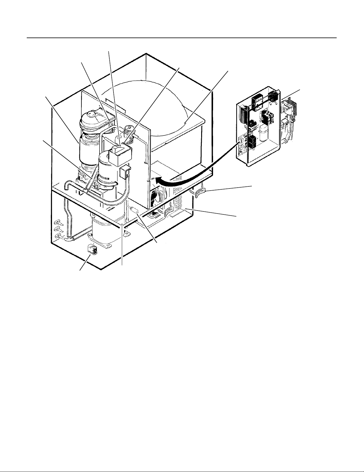
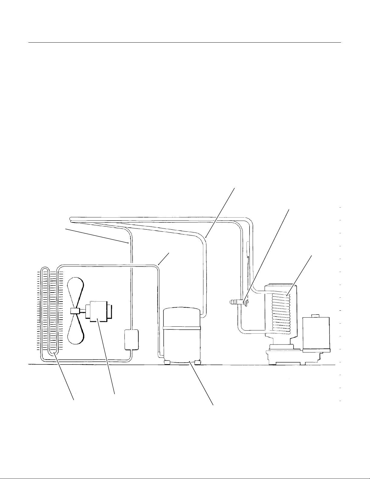
NDE750
COMPONENT DESCRIPTION
ICE LEVEL SENSOR
EVAPORATO R
DRAIN
DRAIN
TUBE
TUBE
RESERVOIR
WATER
LEVEL
SENSOR
ICE STORAGE BIN
CONTROL BOX
GLASS FILLER
CONDENSER
HI
PRESSURE
CUT OUT
PORTION
CONTROL KNOB
PRESSURE
CUT OUT
Control Box:
LOW
Contains the electrical controls that
operate the mach ine.
High Pressure Cut Out Switch
: A manual reset
switc h sensing the high s ide refrigerati on pr es s ur e.
It is set to shut the machine off if the discharge
pressu re s ho uld ever exceed 450 ps i g .
Evapo ra tor:
A vertical stainless steel tube,
refrigerated, and water filled. In it there is a
stainless steel auger.
Reservoir:
Float operated, it maintains the water
level i n th e ev a po r at or at a c o nstant l ev el , it al s o
contains the water level sensor.
Water Level Sensor:
Senses if there is water in
the reservoir to make ice out of. Will shut the
machin e off it th ere i s no ne .
Low Pressure Cut Out Switch:
A manual reset
control that shuts off the ice machine when the low
side pressure drops below a preset point, 0-4 psig.
Ice Leve l Se n so r :
An electronic “eye”, it senses
the pres en ce of ice in th e bottom of the ic e
discharge chute. Operates to turn the ice machine
on and off automatically as the level of ice in the
bin chan ges.
Drain Tube
: When un capped an d l owered, drai ns
the evap or ator.
Condenser:
Air or water c oo l ed , w he r e th e he at
remov ed in ic e m ak ing is dis charged.
Ice Storage Bin Assembly:
A plast i c lined,
insulated cylinder that receives, stores and
dispenses the ice. Fresh ice enters at the top, and
when the bin is full enough the ice will be between
the ice level sensors, and the icemaking will stop.
Ice is dispensed through a chute at the bottom
front when the agi tator assem bly sweeps the ice
through the chute.
Glass Filler L e ve r:
Pushing in on this lever
causes the ice dispensing cycle to occur.
Portion Control Knob:
Turning this knob adjusts
the length of tim e of dispense. No t standa rd af t er
6/97.
May 1997
Page 8
Page 9
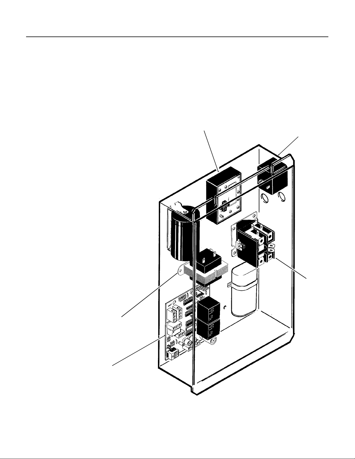
COMPONENT DESCRIPTION: Control Box
NDE750
Contactor:
connecting the comp res sor to the po w er s up ply .
Circuit Board:
through sensors and relays. The sensors are for
ice level and water level. The relays are for the
gear mot or (w ith a buil t i n ti m e delay to cle ar the
evaporator of ice when the unit turns off) and for
the compressor.
On/Off Switch :
Transformer:
board.
Potent ia l Rel ay
Portion Control Module:
time th e dispensi ng drive motor is
on. The time is varied by adjusting
the portion control knob.
Note: Portion control not standard
on units mfg. after 6/97. May be
added on with kit KPC 7 50.
A definite purpose con ta c t or
Controlling the ice machine
Manual co ntrol for th e m ac h i ne .
Supplies low voltage to the circuit
: The compressor start relay.
Controls the amoun t of
PORTION CONTROL
POTENTIA L R ELAY
TRANSFORMER
CIRCUIT BOARD
CONTACTOR
May 1997
Page 9
Page 10
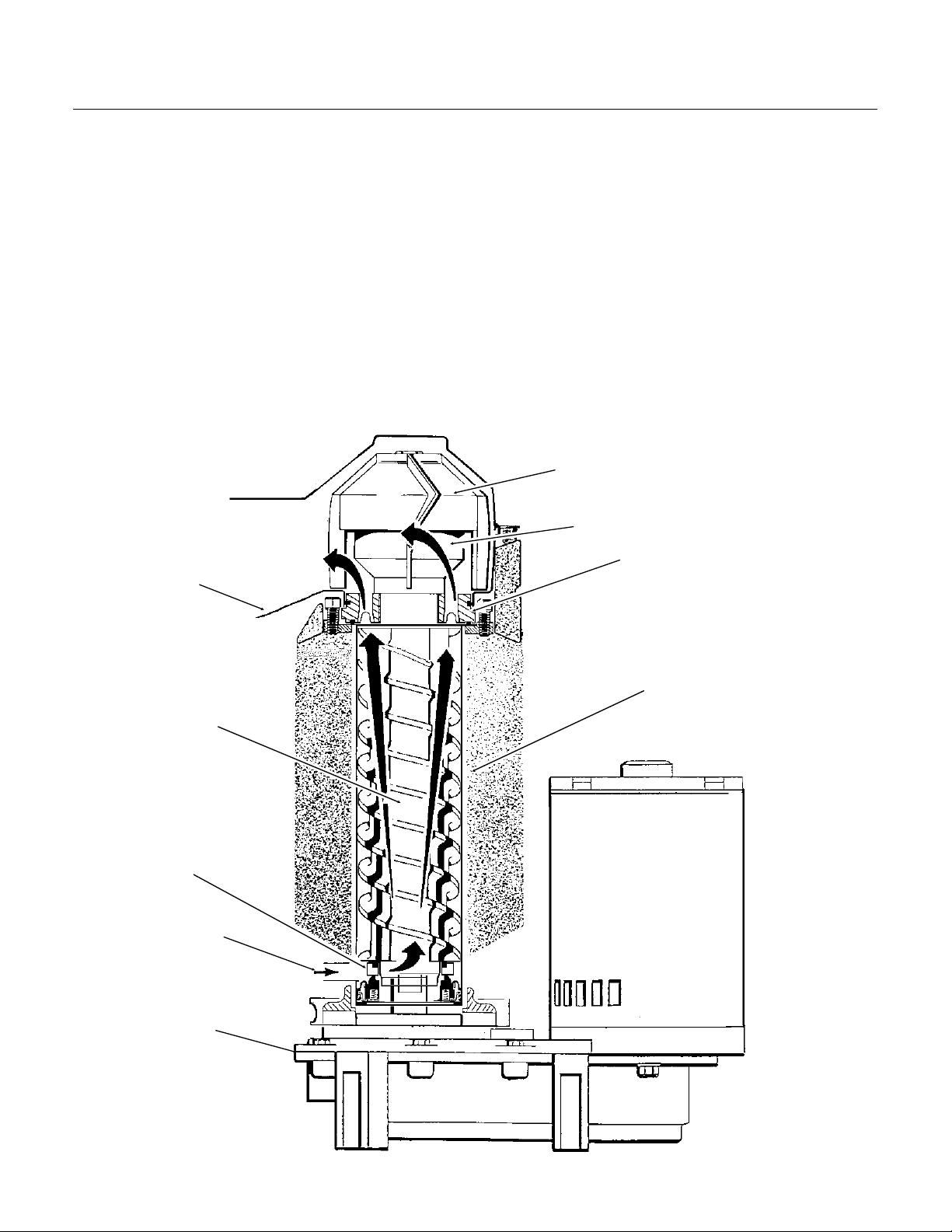
NDE750
COMPONENT DESCRIPTION
Evaporator: A refrigerated vertical tube filled with
water and containing a water seal and auger.
Auger: A solid stainless steel double spiral auger,
it pushes the ice crystals up to the top of the
evaporator.
Water Seal: A two part "face" seal, the top half
rotating with the auger, the bottom half stationary,
the sealing action being where the two seal "faces"
meet.
Ice Sweep: A plastic cap with "fingers". It revolves
with the auger to "sweep" the ice into the ice chute.
Breaker: Where the ice is compressed and much
of the extra water is squeezed out of it before it is
discharged into the bin.
ICE CHUTE
Motor: A split phase motor that drives the gear
reducer.
Thrust Bearing: As the ice is pushed up the
evaporator, the auger is thrust down, and pressure
from the auger thrust is taken up by this bearing.
ICE SWEEP
BEARING
BREAKER
AUGER
WATER SEAL
WATER INLET
GEAR MOTOR
EVAPORATOR
December 1993
Page 10
Page 11

ELECTRICAL SEQUENCE
NDE750
Refer the wiring diagram as needed.
If the machine is switched off at the master switch,
but is otherwise ready to go, switching the master
switch to on does the following:
••The bin empty light on the circuit board goes on
••
There is a 15 second delay
••If there is enough water in the reservoir, the
circuit board will allow the machine to start up.
Start up consists of:
••The compressor relay and auger motor relay
become energized, connecting power to the
windings of the auger motor.
••The auger motor starts, and the centrifugal
switch closes, connecting power to the
compressor contactor coil.
••The contactor is energized, connecting power
to the compressor, and the compressor starts.
••As ice goes past the ice level sensors, the bin
empty light will stay on, and the machine will
continue to run, unless the ice stays between
the sensors for more than 15 seconds (bin full).
At that point, the bin empty light goes out, and
the machine shuts down.
Shut Down consists of:
••The compressor relay opens.
••The compressor contactor opens
••The compressor stops
••The auger motor is run by the circuit board for 2
more minutes, clearing out ice in the
evaporator, and then
••The auger motor relay opens, and the auger
motor stops.
If the ice level sensor is clear (bin empty) for more
than 15 seconds, the machine will start up again.
Another purpose of the circuit board is to turn the
machine off if there is not enough water in the
machine.
••When the water level in the reservoir falls
below the water level sensor, the machine will
“shut down”
••When the water refills the reservoir, the
machine will start up again.
Separate from the circuit board:
••If the high pressure control (cut out switch)
opens, the machine will stop immediately
(through the relays on the circuit board). It must
be manually reset .
••If the low pressure control (cut out switch)
opens, the machine will stop immediately
(through the relays on the circuit board). It must
be manually reset.
••The master switch is the manual control for the
complete machine, but it is not a service
disconnect.
Ice Vending
••When the glass filler lever is pushed in the vend
switch closes. That energizes the ice chute
door solenoid, and the portion control module,
which, depending upon the setting of the
portion control knob, will power the agitator
drive motor for a set length of time.
••Holding the glass filler lever in will not cause
additional dispensing, unless the portion control
is set for continuous dispensing. Releasing and
re-pushing the glass filler lever will repeat the
dispense cycle.
December 1993
Page 11
Page 12

BIN DRAIN
NDE750
OPERATION: Water
Water enters the machine through the 3/8" male
flare at the rear of the cabinet, goes to a strainer
and then to the water reservoir which it enters
through the float valve. The water then goes out
the bottom of the reservoir tank to the bottom of
the evaporator.
Reservoir overflow, evaporator condensation and
water in the sink are all routed to the drain. Water
cooled models have a separate water circuit for
the cooling water: it enters the fitting at the rear,
goes to the water regulating valve, then to the
water cooled condenser and down the drain.
The water dispensing station adds an
additional water circuit. When the water
station glass filler lever is pushed, a switch
closes a circuit to an electric water valve, and
water is dispensed.
RESERVOIR
Note: The correct water level is determined when
the machine is operating. Check the water level
and compare it to the line molded into the side of
the reservoir. The water level should be between
If needed, adjust the water level by bending the
WATER LEVEL
1
⁄8" above and 1⁄4" below the line.
float arm.
RESERVOIR
OVERFLOW DRAIN
WATER
INLET
WATER VALVE
SINK DRAIN
WATER SCHEMATIC
December 1993
Page 12
Page 13
OPERATION: Refrigeration
SUCTION LINE
THERMOSTATIC
EXPANSION VALVE
EVAPORATOR
NDE750
Beginning at the compressor, the refrigerant is
compressed into a high temperature gas. The
discharge line directs this gas to the condenser. At
the condenser (air or water cooled) the gas is
cooled by either air or water and it then condenses
into a liquid. This high pressure liquid then goes
through the liquid line to the expansion valve.
The thermostatic expansion valve meters liquid
refrigerant into the evaporator, the volume of liquid
refrigerant depending upon the temperature of the
evaporator; warmer evaporators get more
refrigerant and colder evaporators get less.
REFRIGERATION SCHEMATIC
(AIR COOLED SHOWN)
At the evaporator, the refrigerant enters an area of
relatively low pressure, where it can easily “boil off”
or evaporate. As it evaporates, it absorbs heat
from the evaporator and whatever is in contact
with it (such as the water inside it). After the
evaporator, the refrigerant, now a low pressure
vapor, goes through the suction line back to
compressor, where the cycle is repeated.
LIQUID LINE
DISCHARGE
LINE
FAN MOTOR
CONDENSER
COMPRESSOR
December 1993
Page 13
Page 14
DOOR
SOLENOID
ICE CHUTE
DOOR
ICE CHUTE
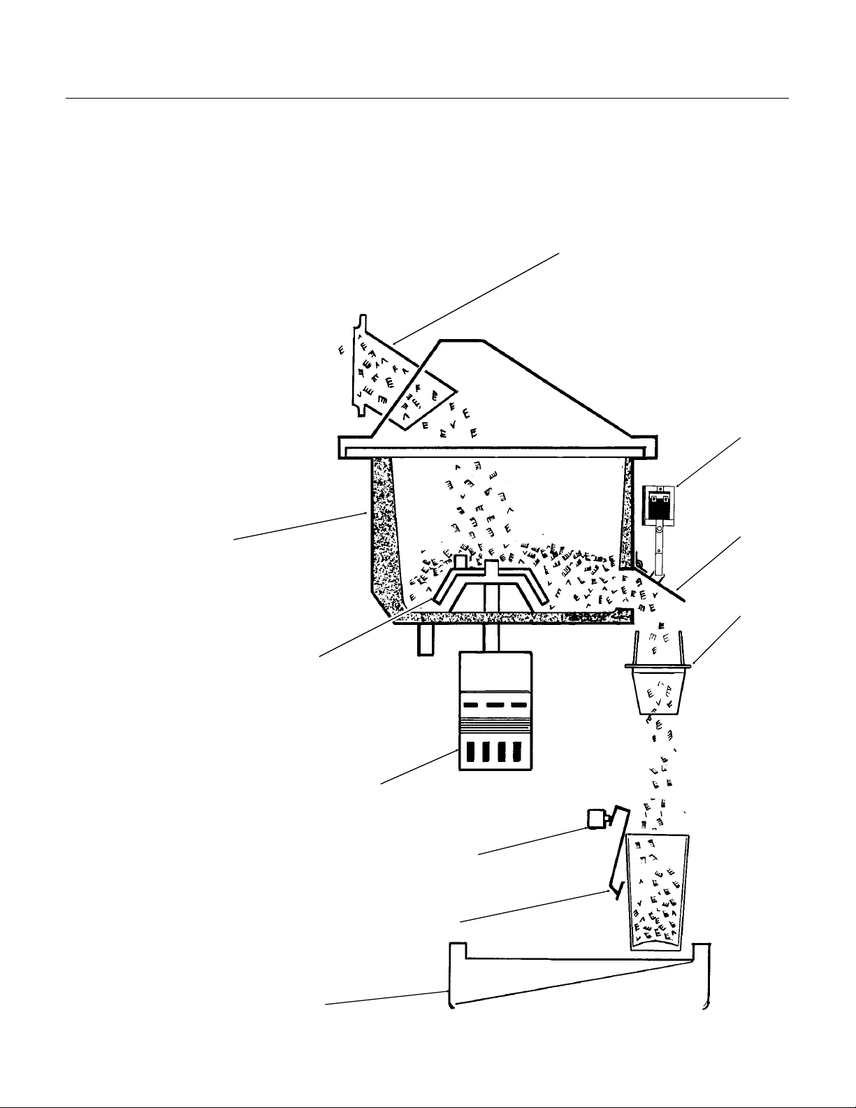
NDE750
OPERATION: Ice Vending
When the ice dispensing glass filler lever is
pushed, an electrical circuit is made to the ice
chute door solenoid causing the ice chute door to
open. At the same time power is connected to the
portion control module in the control box. That
module will energize the agitator drive motor for a
certain length of time, depending upon the setting
of the portion control knob.
The dispensing takes place when the agitator
sweeps the ice through the ice dispensing chute:
ice will continue to
discharge out this chute as
long as the agitator is
turning. It stops when the
agitator stops.
ICE DISCHARGE CHUTE
STORAGE BIN
AGITATOR
AGITATOR
DRIVE MOTOR
VEND SWITCH
GLASS FILLER
LEVER
SINK
December 1993
Page 14
Page 15

NDE750
CLEANING and SANITIZING
A Scotsman Ice System represents a sizable investment of time and money in any company’s
business. In order to receive the best return for that investment, it MUST receive periodic
maintenance.
It is the USER’S RESPONSIBILITY to see that the unit is properly maintained. It is always
preferable, and less costly in the long run, to avoid possible down time by keeping it clean;
adjusting it as needed; and by replacing worn parts before they can cause failure. The following
is a list of recommended maintenance that will help keep the machine running with a minimum of
problems.
Cleaning should be scheduled at a minimum of twice per year.
Sanitizing of the ice storage bin should be scheduled for a minimum of 4 times a year.
8. Slowly pour the cleaning solution into the water
Electrical power will be ON when doing in
place cleaning.
ICEMAKING SYSTEM: In place cleaning
1. Check and clean any water treatment devices, if
any are installed.
2. Remove screws and remove the upper front
panel.
3. Move the ON-OFF switch to OFF.
4. Remove the cover to the ice storage bin, and
remove the ice.
5. Remove the cover to the water reservoir and
block the float up.
6. Drain the water reservoir and freezer assembly
using the drain tube attached to the freezer water
inlet. Return the drain tube to its normal upright
position and replace the end cap.
Scotsman Ice Machine
Cleaner contains acids.
These compounds may
cause burns. If swallowed,
DO NOT induce vomiting.
Give large amounts of
water or milk. Call
Physician immediately. In
case of external contact,
flush with water. Keep out
of the reach of children.
reservoir until it is full. Wait 15 minutes, then
switch the master switch to ON.
9. As the ice maker begins to use water from the
reservoir, continue to add more cleaning solution
to maintain a full reservoir.
10. After all of the cleaning solution has been
added to the reservoir, and the reservoir is nearly
empty, switch the master switch to OFF.
11. After draining the reservoir, as in step 6, wash
and rinse the water reservoir.
To Sanitize:
Repeat steps 8-11, except substitute sanitizer
solution for the cleaning solution.
A possible sanitizer solution may be made by
mixing 1 ounce of household bleach and 2 gallons
of warm (95
12. Remove the block from the float in the water
reservoir.
13. Switch the master switch to ON
14. Continue ice making for at least 15 minutes, to
flush out any cleaning solution. Check ice for acid
taste - continue icemaking until ice tastes sweet.
DO NOT USE any ice produced from the
cleaning solution.
Be sure no ice remains in the bin.
o
F. - 115oF.) potable water.
7. Prepare the cleaning solution: Mix eight ounces
of Scotsman Ice Machine Cleaner with three
quarts of hot water. The water should be between
90-115 degrees F.
December 1993
15. Remove all ice from the storage bin.
16. Add warm water to the ice storage bin and
thoroughly wash and rinse all surfaces within the
bin.
17. Sanitize the bin interior, cover, door and
agitator with an approved sanitizer using the
directions for that sanitizer.
18. Replace the ice storage bin cover, and the
front panel.
Page 15
Page 16
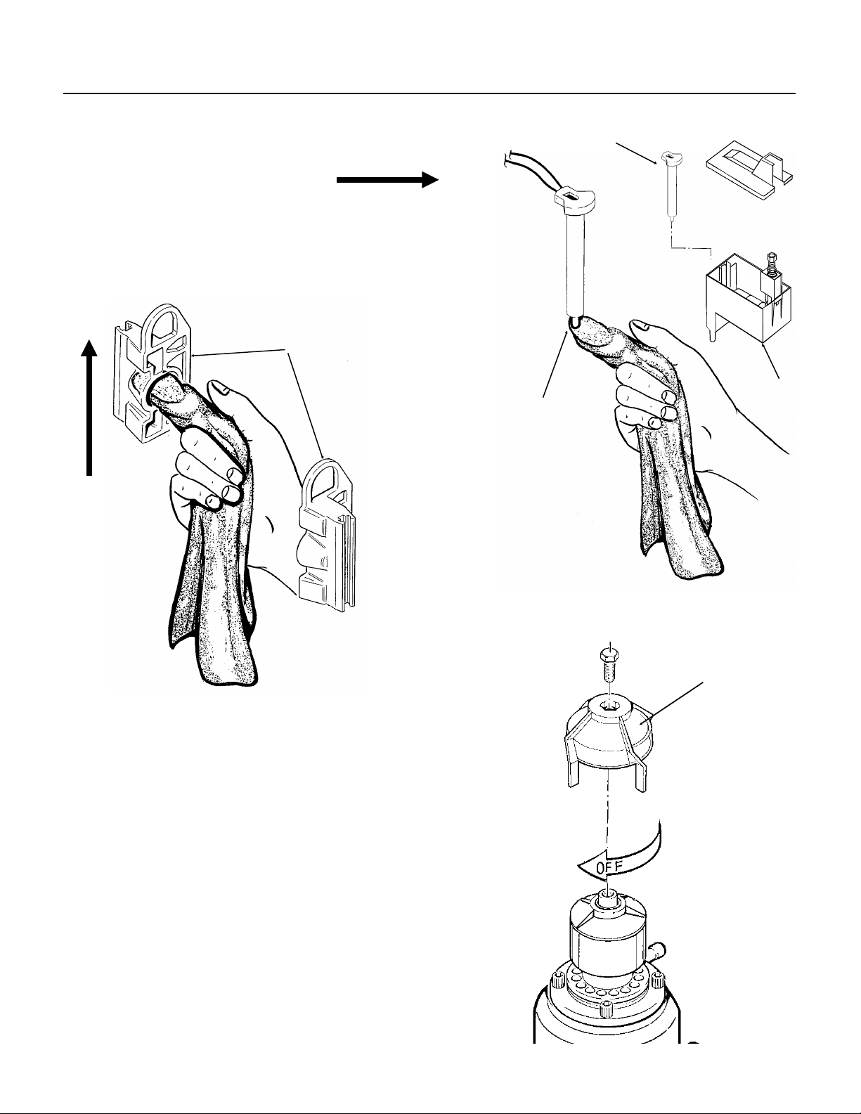
PROBE
RESERVOI R
NDE750
MAINTENANCE AND CLEANING
1. The ice mach ine senses wat er level by a probe
located in the water rese rvoir. At least twic e a
year, the probe shou ld be re move d fro m the
reservoir, and the tip wipe d clea n of minera l
build-up.
2. The bin control uses devices that sen se ligh t,
therefore they must be kept clean enough so that
they can “see”. At least twice a year, remove the
bin control sensors from the ice ch ute, and wipe
them clean.
SLIDE SENSORS
UP TO REMOVE
CLEAN THE TIP
//////////////////////////////
CAUTION: TH E
TIP IS MADE OF
GLASS;
/////////////////////////////
3. The bearin g i n the bre aker sh ould al s o be
checked at lea st two times per year.
A. Check the bearing by:
••removing the ice chute cover
••unscrewing the ice sweep
••removing the water shed
••u nscrewing the breaker cover.
••unscrewing the auger stud
Inspect the asse mbly , looking for wea r.
See Removal and Replacement to replace
bearing or seals. Reverse to reassemble.
4. Check and tighte n all bolts and screws.
ICE SWEEP
December 1993
Page 16
Page 17

MAINTENANCE AND CLEANING: Auger
In some areas, th e wat er supply to the ic e maker
will contain a high concentratio n of minera ls, and
that will result in an evaporator and auger
becoming coated with thes e mine rals, requirin g a
more frequent removal than twice per year. If in
doubt about the cond itio n of the evaporator and
auger, the auger can be removed so the parts can
be inspected.
Note: Water filte rs can filt er out sus pended solids,
but not dissolved solids . “Soft” wat er may no t be
the complete answe r. Che ck with a wate r
treatmen t specia list regarding wat er trea tme nt .
For more information on removal of these
parts, see REMOVAL AND REPLACEMENT.
Moving Parts Hazard.
Disconnect electrical
power to the icemaker dispenser before
beginning.
NDE750
BREAKER AND
AUGER ASSEMBL Y
Disconnect electrical power, and shut off the
water supply.
Use care when removing the auger, it has
sharp edges.
1. To remove the auger, remove the fron t an d top
panels.
2. Drain evaporat or using drain hose.
3. Remove bail clamp from over ice ch ute cov er
and remove cover.
4. Unscrew and remove ice sweep.
5. Remove ice chute from ev aporat or.
6. Remove 4 allen screws holding break er to
evaporat or.
7. Pull up to remove auger.
After the auger has been removed, allow the auger
to dry: if the auger is not bright and shiny, it must
be cleaned.
Clean the auger and evap ora to r as req uire d. DO
NOT HONE THE EVAPORA TO R.
8. Replace the water seal.
9. Reverse to reassemble.
Air Cooled Model
Clean the air cooled conde nser wh eneve r the ice
machine water system is cleaned, more frequently
if in a dusty or greasy area.
1. Shut off elect ric al po wer.
2. Remove right side service panel.
3. Brush off condenser fins, use soft bristle brush
or vacuum.
4. Check with light to see if fins are clean all the
way through.
5. Use coil cleaner if grea se is deep inside fins .
6. Replace service panel and reconn ect powe r.
December 1993
Page 17
Page 18

NDE750
SERVICE DIAGNOSIS: Condition - No Ice Being Produced
STATUS:
A. Check: Voltage to the unit, restore power if there is none. Compare to the nameplate.
B. Check: The master switch, switch ON if off.
C. Check: The reset switches, (high and low pressure): depress and release each switch. If the
machine still does not start, check: the high and the low side pressures.
D. Check the low pressure cut out, if closed, go to E; if it is open, it could be due to:
ICE MAKER DOES NOT OPERATE
••Low refrigerant charge
••The auger not turning
••Restricted system
•• TXV not open in g
1. Check the low side pre ssu re, th e low pre ssu re cut out opens at press ure below 4 ps ig.
If op en, reset and:
a. Check if the auger is turning, if it is not, remove the gearbox an d:
Check for internal damag e, repair and replace in the machine.
b. Check for low charge, add some refrige rant , if th e unit will operate,(normal
low side pressure being about 38 psig) sto p and loo k for a lea k, rep air, rep lace the
drier, evacuate , and weig h in the namep late charge. If , with added charg e, the unit
does not operate:
Check for a restricted syste m, repla ce the drier, evacu at e, and weigh in a
nameplate charge.
Check for a Ther mostatic Expan sion Valve that does not open, if defective,
replace it. Replace the drier, evacuate, and weigh in the nameplate charge.
E. Check the high pressure cut out, if closed, go to F; if open:
1. The pressure con trol op ens at 450 psig. Check the high side press ure, reset the control,
and observe: on water cooled, that water soon begins to flow from the condenser drain;
or, on air cooled, that th e fan is forc ing ai r throu gh the cond ense r. If the unit trips out on
pressures below 450 psig, replace the control. If the pressures rise above the trip out
point, and the unit shuts down:
a. Check for adequat e wat er flo w on wat er coo led , if ad eq uate , clea n the int erio r
of the condense r. If th e pre ssu res are still too high replac e th e water re gulating valve .
b. Check for adequat e air flo w on air cooled . Clea n the con dens er and (if used) the
filter. If the air f low is poo r beca us e of the installation , advise the user that the unit
should be moved, or the air around it kept cooler.
Check the fan motor for tight bearings and proper rotation.
Check that the fan blad es are clean, and the fa n se cure to the fa n mot or shaft .
F. Check the water level in the re servoir. The machine will not run if there is not enou gh water in the
reservoir.
1. Restore/adjust water level. See the next step.
December 1993
Page 18
Page 19

SERVICE DIAGNOSIS: Condition - No Ice Being Produced
NDE750
STATUS:
ICE MAKER DOES NOT OPERATE
G. Check: The gear motor, if it will not run, the compressor will not run. If no power to it:
Check: The indicator lights on the circuit board, the bin empty light should be ON, the no water light
should be OFF .
1. If the bin empty and no wa ter lights are off, check the transformer.
a. Transformer “loa d” side shou ld have 12 to 15 volts. If not, check th e “line ” side. The line
side should have betwee n 110-120 volts. If th e line sid e has the correc t volt ag e and the
load side does not, replac e th e transformer.
2. If the transformer is g ood, and the b in empty light is OFF, check th e ic e le ve l se n so r s.
a. Remove sensors by pullin g them out of the ice chute grommet s. Visually inspe ct them,
clean if needed .
b. Look thro ug h the ice ch ute “eye ” hole fo r something blocking the ice chute.
c. If the unit still does not run , replace the ice leve l sens ors.
d. If the bin empty light is still OFF, check the circuit board.
1. Unplug “opto trans” an d “LED” connect ors from th e circu it board.
2. Plug “opto trans” and “LED” connectors from the Scotsman Electronic Control
Tester Model N M1 into the circu it board.
a. Move the “bin full” switch on the tester to the full pos itio n. The bin full light
on the tester should be ON, if no t, repla ce th e circu it bo ard.
If the bin full light on the tester is ON, move the test er switc h to “bin empty ”
the light on the tester should go OFF and the bin empty light on the circuit
board should go ON. If not, repla ce the circuit board. If it does as above ,
and the machine still do es not run , replace the ice leve l sens ors.
3. If the transf ormer is fine, and the “no wate r” ligh t is ON, ch eck the water level sensor.
a. Check the water level in the reservoir, restore if low. If the wate r level is ok:
b. Remove the water level sensor from the reservoir and clean the tip if dirty.
CAUTION: THE TIP IS MADE OF GLASS
c. Replace the water level sen so r. If the no water light is still on, check that the
"water sen" plug is firmly plugged into the circuit board.
d. If the no water light is still on,
1. Unplug the “water sen” connect or from the circuit board.
2. Plug “water sen” conn ec to r from the Scot sman Electro nic Con tro l t est er int o
the circuit board.
a. Move the water switch on the test er to “no wate r ” and the no water light
on the circuit board shou ld go on. If not, rep lace the board.
b. Move the water switch to the “water” position, the no water light should
go off, if not, replace the circuit board.
c. If after the above, the mac hin e still will not run, replac e the wat er leve l
sensor
MORE INFORMATI ON ON THE TEST ER MAY BE FOUND AT THE BACK OF THE MANUA L.
December 1993
Page 19
Page 20

NDE750
SERVICE DIAGNOSIS: Condition - No Ice Being Produced
STATUS:
A. Check the compressor relay.
The relay is on the circuit board, if it does not su pply powe r to the contact or coil, the
compressor will not run.
1. Check for power at the con tactor coil, if none:
2. Check the contactor coil. If the coil is open, replac e the conta ct or.
3. Check the auger drive motor centrifugal switch. If, whe n the drive mo tor is running ,
contact 4 (black wire removed ) has no power, and all of the abov e switche s have been
checked, replace the centrifugal swit ch, or the drive motor.
4. If the compressor relay on the circuit board has power on the NO contact, but not on the COM contact,
replace the circuit board.
B. Check the compressor
1. Check the compressor start relay.
2. Check the start capacitor.
3. Check the windings of the comp re sso r for ope n wind ing s or sho rt s to groun d.
Replace those items fo un d defe ct ive.
GEARMOTOR OPERATES, COMPRESSOR DOES NOT
a. Check for power at the compress or relay at the ci rc uit board.
If there is power at the relay, but none at the contactor coil,
Check for an open wire between the relay and the conta ct or.
December 1993
Page 20
Page 21

SERVICE DIAGNOSIS: Condition - Low Ice Production
NDE750
STATUS:
A. Check the air cooled condenser for dirt. Clean as required. Check the head pressure on water
cooled. Adjust as required. If the head pressure is very high:
1. Air cooled. Check for high air te mperatur es, or restrictive air flow. Correct as needed.
3. The refrigerant may contain non condensable gases, purge, evacuate, and recharge per nameplate.
B. Check the evaporator
1. Clean the evaporato r, the mineral build up will adversely affect the ice machin es produ cti on.
3. Check the low side pressure; nor mal is about 38 psig. If lo w, assume a refr iger ant leak,
4. Check the insulation on the evapor ato r. It shoul d be dry, with no wet spots or frost.
EVERYTHING IS OPERATING
2. Water cooled. Check for high wate r te mpera tur es, or lo w water pressu re.
Correct as needed.
2. Check the evaporator for water leaks, repla ce the water seal if found t o be leakin g.
locate, repair and recharge.
If no leak, the TXV may be restricted, defective or not adjusted prop erl y. If needed,
replace the TXV, evacuate, and recharge per nameplate.
If the insulation has failed: replace the evaporator or add extra insulation in the form
C. Check the compressor.
b. if the amp draw is normal, pinch off the suction line to check the pull down capability
of the compressor. The compressor should pull down to 25 inches of vacuum and hold
of foam tape to the evaporator.
1. The compressor may be inefficient.
a. Check the amp draw, if low change the co mpressor.
there for three to five minutes.
December 1993
Page 21
Page 22

NDE750
SERVICE DIAGNOSIS: Condition - Poor or No Ice Dispensing
STATUS:
A. Check for ice in the bin, if no ice, check the ice making system.
If the ice making syst em is norma l, the deman d fo r ice may exc eed th e quantit y the icema ker can produce .
Check with the use r on ice usage: advise the user that anoth er mach ine may be needed.
B. Check for motion in the agitator when the glass filler lever is pushed, if no motion: Check the vend
switch, if it does not close when the glass filler lever is pushed, replace the switch.
If the vend switch does clos e, chec k for volt ag e at the agitat or drive motor. If th ere is volta ge , and the
agitator motor output shaft does not turn, replace the agitator gear motor assembly.
C. Check that the ice dispensing door opens when the glass filler lever is pushed. If not, check the
vend switch. If the vend switch is good, check the door solenoid.
If the agitator mo ve s when it is supposed to, and there is ice, the dis pe nsin g cyc le sho uld be fin e.
is dispensed, chec k for an obst ruction in the ice chu te.
D. No portion control.
1. Continuous dispensing when the glas s filler leve r is pushed in: Che ck fo r an open potent iome te r (portio n
control). If open, replac e it.
If it is not open, replace the portion control module in the control box.
2. Very short dispensing: Check for a shorted poten tio met er (p ort ion cont rol). If short ed, rep lace it.
If it is not shorted, repla ce th e portio n control module in the control box.
There is power to the unit, but no ice is dispense d
December 1993
Page 22
Page 23

REMOVAL AND REPLACEMENT
NDE750
WATER RESERVOIR
1. Shut off the water supply to the icemaker.
2. Remove front pane l and reservo ir cove r.
3. To remove float only, pry the moun tin g flang es
apart enough to lif t one flo at pivot pin out of the
flange hole, and pull float up and out of the
reservoir.
4. To remove reservoir, dis con ne ct water inle t
compression fitt ing at reservoir inle t.
5. Remove drain hose from reservoir.
6. Remove evaporator inlet hose from reservoir.
7. Remove water level sensor probe.
8. Remove mounting screws from rese rvoir
bracket, and remove reservoir from icemaker.
9. Reverse to reassemble.
FLOAT
VALVE
BIN CONTROLS (Ice Level Sensors)
1. Disconnect electrical power.
2. Remove front panel.
3. Remove control box cover.
4. Locate bin top, in front of and behind it are two
rubber bin control gro mmet s.
5. Pull each bin contro l out , and in the con tro l box,
disconnect the electrical lea ds connecting the bin
control to the circuit board.
6. Reverse to reassemble, be certain that the bin
controls are alig ne d so that th e ice lev el sen so rs
are visible (cent ered ) t hrou gh the hole s in the ice
chut e.
VAL VE
PLUNGER
LOCKING TAB
December 1993
Page 23
Page 24

BEARING
STEPS 5-C
AND 6
NDE750
REMOVAL AND REPLACEMENT: Bearing And Breaker
Note: Remov al of the auger, wat er sea l,
evaporator and gearmotor must begin at the top of
the assembly.
To Remove the Breaker Bearing Assembly:
Moving Parts Hazard.
Disconnect electrical
power to the icemaker dispenser before
beginning.
1. Remove panels and disconnec t ele ctrica l power.
2. Unscrew three stu ds and remo ve ice chut e
cover.
3. Unscrew and remove ice sweep.
4. Remove insulation halv es fro m out side of ice
chute, lift up and remove ice chute.
5. The breaker may be removed from the auger
and evaporator without disturb ing the auger.
a. Unscrew breaker cover from breaker (left hand
threads)
b. Unscrew auger stud from top of auger.
c. Unscrew 4 allen head cap screws holding
breaker to eva po ra t or .
d. Lift up, and remove bre aker/bearing assembly
from auger & evaporator.
6. Service the bearing. Che ck fo r rust, rough spo ts
and da m age.
a. The bearing is presse d into th e breaker, to
remove the bearin g and replace it an arbor p ress
is ne eded .
b. Replace lower seals be fore installing new
bearing in breaker.
Note: seals must be pres sed in with a tool pu sh ing
against the outer edge only, they will not install by
hand.
Replace parts as required. Re-g reas e bearing with
Scotsman part no. 19-0609-01 bearing grease.
Replace to p sea l, and ch eck the o-rin gs, repla ce if
cut or torn.
7. Revers e to reassemble: sp ecific to ols an d
materials are requ ired to install pro pe rly .
a. Add food grade greas e suc h as Scot sman part
number 19-05 69 -01 to th e sea l area bef ore
installing on the auger.
b. Check the seal to shaft areas for cuts, or rough
spots: none are permitted.
ICE SWEEP
STEP 5-A STEP 5-B
BREAKER
December 1993
Page 24
Page 25

REMOVAL AND REPLACEMENT
SLIDE HAMMER
PULLER
NDE750
To Remove the Auger:
Turn off the wate r to the mach ine , and unclip the
evaporator drain hose, pull it down and drain the
evaporat or int o th e bin or a cont ainer.
Moving Parts Hazard.
Disconnect electrical
power to the icemaker dispenser before
beginning.
1. The top panel must be removed.
2. Remove ice chute cov er.
3. Unscrew ice sweep.
4. Remove ice chut e body.
5. The auger and breaker/bearing may now be
removed as an assembly.
BREAKER/
BEARING/
AUGER
ASSEMBLY
SHARP EDGES!
e. If the auger is stuck use a slide hammer type
puller to pull on the auger at the threade d hole.
The size of that hole is 5/8"-18.
Inspect the auger, the critical areas of the auger
are:
1. The auge r body . It s hould be clean and
shining. Sometimes an auger will appear clean
when wet, but after it is dry it will be seen to be
stained . Scrub the auger with ice machin e cle an er
and ho t wa ter.
Ice machine cleaner is an acid. Handle it with
extreme care, keep out of the reach of children.
2. The water seal area. Because the auger has
been removed, the wate r seal will hav e to be
replaced. Remove the wate r se al to p half from th e
auger, and inspect the auger for minerals clean as
required.
a. Unscrew 4 allen head cap screws hold ing
breaker to eva po ra t or .
b. Lift up on breaker and remove auger from
evaporat or.
Note: If the auger is stuck, the breaker must be
removed from the auger.
The breake r may be removed from the auger an d
evaporator without disturb ing the auger.
a. Unscrew breaker cover from breaker (left hand
threads)
b. Unscrew auger stud from top of auger.
c. Unscrew 4 allen head cap screws holding
breaker to eva po ra t or .
d. Lift up & remove breaker from evap orat or.
THREAD INTO
AUGER
December 1993
Page 25
Page 26

NDE750
REMOVAL AND REPLACEMENT: Water Seal
To Remove the Water Seal:
(Assuming all steps to remove the auger have
been performed.)
1. The gearmotor/evaporator assembly will have to
be exposed. (See illustration - next page)
2. Remove the 4 hex head cap screws holding the
evaporator to the gearmoto r asse mbly. Lift the
evaporator up and off of the gearmotor.
3. Remove the snap ring or wire retainer from the
grove under the water seal.
4. Pull or drive out the lower half of the water sea l.
To Replace the Water Seal:
1. Lubricate the water seal with wat er, and push
the water seal in to the bot to m of th e ev aporator
slightly past th e grove fo r the snap ring .
19-0529-01) on the area of the auger where the
water seal is to be mounted.
5. Carefully push the water seal (rubber side
against the auger shoulder and the silastic.)
/////////////////////////////CAUTION///////////////////////////
Do not get any silastic onto the face of the seal.
/////////////////////////////////////////////////////////////////////////
6. Allow the auger and seal to air dry until the
silastic is dry on the surface.
WATER SEAL
RETAINING RING
2. Replace the snap ring and pull the water seal
down against it.
3. The part of the water seal that rota tes wit h the
auger must also be replac ed . Remove the old part
from the auger and clean the mounting area.
4. Place a small bead of food grade silastic se alant
(such as 732 RTV or Scot sman part numb er
FOOD GRADE
SEALANT HERE
7. If the origina l wate r se al was lea kin g, it would be
a good idea to inspect the interior of the gearmotor.
December 1993
Page 26
Page 27

REMOVAL AND REPLACEMENT
AUGER
BREAKER
NDE750
To Replace the Evapora tor:
(Assuming all the ste ps for remova l of the thrust
bearing, breaker, au ger, an d water sea l have been
perform ed.)
1. Recover th e refrig eran t fro m the ice make r.
2. Unsweat the refrigerant connections:
a) At the thermostatic expa nsio n valve ou tle t.
//////////////////////////////CAUTION///////////////////////////////
Heat sink the TXV body when unsweating or
resweating the adjacent tubing.
//////////////////////////////////////////////////////////////////////////////
b) At the suction line at the joint ab out 3" from the
evaporat or.
3. Remove the evaporator.
4. Unsweat the dr ier from the
liquid line.
5. After installin g a new water
seal in the new evaporator
(see “To Replace the Water
Seal”) sweat in the new
evaporat or at the old tubin g
connect ions.
6. Install an new drier in the
liquid line.
7. Evacuate the system until
dehydrated, then weigh in the
nameplat e ch arge. Check fo r
leaks.
8. Install auger, breaker,
breaker bearing assembly,
and ice discharge chute in
reverse order of dis assembly.
EVAPORATOR
WATER
SEAL
RETAINING RING
DRIP PAN
To Reassemble the Evaporator and Auger
1. After the gearmot or has bee n ins pecte d, fas te n
the evaporat or to the gear mot or, be sure that th e
number of shims indicated on the gear case cover
is in place between the gearcas e cov er and the
drip pan gasket. Torqu e th e bolts to 110 inch
pounds .
2. Lower the auger into the evaporator barrel,
slightly turning it to match up with the drive end.
Do Not Drop Into the Evap ora to r.
3. Complete the reassembly by reversing the
disassemb ly f or th e brea ker & thrust bearing
assembly.
ICE SWEEP
BREAKER
BEARING
December 1993
Page 27
Page 28

NDE750
TO REMOVE AND REPAIR THE GEARMOTOR ASSEMBLY
(Assuming that the procedures through removal of
the water seal have been performed.)
1. Remove the electrical wires from the gear drive
motor.
Electrical Shock Hazard.
Disconnect electrical
power to the icemaker dispenser before
beginning.
2. Unscrew the 4 cap screws holding the
gearmotor to the gearmotor plate.
3. Remove the gearmotor from the
WATER
SHED
icemaker.
To Inspect the gearmotor.
A) Remove the cap screws holding
the gearmotor case halves together
and pry the two cases apart.
B) To lift off the cover, lift up until
you can feel internal contact, then
pull the cover towards the output
gear end, and then lift the cover
GEARCASE
COVER
(with drive motor attached) up and
away from the gear motor case.
Note: The case cover output gear,
bearings, and shaft are one
pressed together assembly.
Replace as a unit.
C) Inspect the oil, gears, and
bearings. If the oil level and
condition is acceptable, quickly
check the gears and bearings. They
are likely to be fine if the oil is.
If there is evidence of water in the
oil (rusty bearings and gears; the oil
having a creamy white appearance;
oil level too high) carefully inspect
the bearings and gears. If in doubt
about the condition of a part,
replace it. The oil quantity is 14 fluid
ounces, do not overfill.
Note: The gears and bearings are
available only as pressed together
sets.
D) After replacing parts as required, (if any)
reassemble the gearcase. The two smaller gears
and the oil should be in the lower case, the output
gear will be with the cover. As you lower the cover
onto the lower case, cover will have to be moved
closer to the second gear after the output gear has
cleared the second gear top bearing.
E) After the case is together, and the locating pins
are secure in both ends, replace all cap screws.
4. Bench test the gearmotor, check for oil leaks,
noise, and amp draw.
SWITCH
MOTOR
BEARING
ROTOR SEAL
GEAR &
BEARINGS
GEAR &
BEARINGS
GASKET
GEAR CASE
December 1993
Page 28
Page 29

REFRIGERATION SERVICE: R-404a (HP62)
THIS ICE MACHINE USES HP62 REFRIGERANT
AND POLYOLESTER COMPRESSOR OIL.
DO NOT USE MINERAL OIL IN THIS
REFR IGERATIO N SYSTEM.
••HP62 is a "Near Azeotrope", and the ref ore
liquid charging is required.
Weigh into the dis cha rge side as much as poss ible
of the charge as liquid refrigerant.
Install a sight glass betwe en the manif old and ths
suction sid e hose. Caref ully meter liquid refrig erant
into the suctio n sid e, using the ma nif old valve to
"flash off" the liquid before it enters the ice
machine. Do this until th e pro per ch arge has been
weighed into the syste m.
••When the sys tem is se rviced , a sp ecia l liq uid
line dryer is required.
••Polyolest er oil absorbs water very easily, and
therefore whe n the syst em is open ed for
service, it must be re-sealed as soon as
possible (15 minutes maximum).
••Special lea k det ec tio n equip ment is required to
locate small ref rige rant leak s. Usu ally a leak
detector cap ab le of detec ting a Halogenate d
refrigerant or HFC-134A will work. Check with
the leak detector manufact urer if in doub t.
••As with any other refrigerant, do NOT mix HP62
with pressurize d air when lea k tes tin g.
••The vacuum pump or recovery unit should use
polyoles te r oil.
VAPOR VAPOR
TEMP. PRESSURE TEMP. PRESSURE
(DEG F) (PSIG) (DEG F) (PSIG)
-20 17 70 146
-18 18 72 150
-16 20 74 155
-14 21 76 161
-12 23 78 166
-10 24 80 171
-8 26 82 177
-6 28 84 182
-4 29 86 188
-2 31 88 194
0 33 90 200
2 35 92 206
4 37 94 212
6 39 96 219
8 41 98 225
10 43 100 232
12 46 102 239
14 48 104 246
16 50 106 253
18 53 108 260
20 55 110 268
22 58 112 275
24 60 114 283
26 63 116 291
28 66 118 299
30 69 120 307
32 72 122 316
34 75 124 324
36 78 126 333
38 81 128 342
40 85 130 351
42 88 132 360
44 91 134 370
46 95 136 379
48 99 138 389
50 102 140 399
52 106 142 409
54 110 144 420
56 114 146 430
58 118 148 441
Pressure-Temperature Chart for HP62
NDE750
December 1993
Page 29
Page 30

Access Valves
Note: There are no valve
cores in this valve.
NDE750
REFRIGERATION SERVICE
General Information:
Work on the refrigeration syste m sho uld only be
done when it is certain that the system needs
repair.
••Refrain from checking refrigeration
pressures without reason. Visual ins pe ctio n
of the water system, observation of the ice
formation, amp draw, volta ge, and ot her
technique s will lead to prop er dia gnosis.
Scotsma n also recommends that, at the time of
initial start up, gauges not be used.
••If gauges must be used, don’t always check the
high side pressure. If the condenser is clean
and seems to be operating correctly, it most
likely is. The low side press ure is more
important on an ice machine than the high sid e.
••If gauges must be used, use very short ho ses to
minimize refrigerant discharge d int o the air.
••Refrige rant sho uld not be added exc ep t as a
way to determine the proper operation of the
product. If the syste m was low on refrige rant ,
there is a leak, and it must be found and
repaired.
••This system has a critical charge, it must be
recharged with the corre ct amo un t of refrige ran t
as listed on the name pla te of the ice mac hin e,
or performance will suff er.
Recover, reclaim or recycle refrige ran t . The
method chosen is up to the service company. Any
refrigera nt place d int o a Scot sman ice mach ine
must meet ARI spec 700-88. Reclaim progra ms
are available thro ugh most refrige rant wholesa lers.
Access Valves: To use the access valves:
Remove the cap from t he stem, use a 3/16" allen
wrench to check th at the valve is CLOSE D. Th e
remove the core cap .
Close the valve and replace the caps when the
job is finished. The valve must be closed and
the caps must be on or the valve will leak.
Allen
Wrench
Torque Stem to
6-8 ft. lb.
Torque Stem Cap to
8-12 ft. lb.
Torque
Core Cap to
7-12 ft. lb.
••Anytime th e refrig erat ion system has bee n
opened, the dryer should be replaced. Note:
Only a HFC type dryer should be used.
••When brazing the tubing connections to
compone nt s su c h a s the TX V, the com pone nt
must be protect ed by heat sink mat erial.
December 1993
Page 30
Page 31

LIGHT GOES ON
NDE750
CIRCUIT BOARD TESTING
INSTRUCTIONS FOR USING TESTER, (Optional, order part no. A33942-001)
(These instructions assume that the unit will not run, and prior investigation of electric power,
controls, and mechanical parts indicates that the electronic circuit may be at fault.)
Electrical Shock Hazard.
Disconnect electrical
power to the icemaker dispenser before
beginning.
obstructed, use the tester as follows:
Bin Control
electrical power on, the master switch on, and all
reset swit che s “re set ”.
1. Unplug “phot o tran s” and “L ED” conne cto rs f rom
the circuit board.
2. Plug “photo tra ns ” and “LE D ” conn ect ors from
the tester into the circuit board.
a. Move the “bin full” switch on the tester to Full.
The light on the test er sho uld be ON.
If the light on the tester is not on, the circuit board
should be replaced.
Note: All test ing is done with the
If the "NO WATER" indicator is lit, but
inspection shows that the water level in the
reservoir is above the top of the water level
sensor, OR the "BIN EMPTY" indicator is off
while inspection shows that the ice level
sensors are properly aligned, clean and not
b. If the light on the tester IS on, move the “bin
full” switch to Bin Empty. The light on the tester
should go OFF, and the Bin Emp ty ligh t on the
circuit board should go ON.
If the Bin Empty light is ON, wait 10-20 seconds for
the machine to start , if th e mach ine sta rt s, replac e
the ice level sensors.
If the Bin Empty light does not co me ON, the
circuit board should be replaced.
PHOTO
TRANS
SWITCH TO
“FULL”
LED
LIGHT GOES
ON
December 1993
Page 31
LIGHT OFF
SWITCH TO
“BIN EMPTY”
Page 32

NDE750
CIRCUIT BOARD TESTING
Water Level
1. Unplug “water sen” connector from control
board.
2. Plug “water sen” connect or from Sc ot sman
tester into circuit board.
a. Move “water” switch on tester to No Water
position. The No Water ligh t on the circuit board
should go ON. If not, replac e the circuit board.
LIGHT ON
WATER SENS
b. Move the “water” switch on the tester to the
Water position. The No Water light on the board
should go OFF. If not replac e the circuit board. If
the light does go off, replac e th e water leve l
sensor .
If the Bin Empty light is ON, wait 10-20 seconds for
the machine to start . The machine shou ld st art.
LIGHT OFF
SWITCH TO
“NO WATER”
SWITCH TO
“WATER”
December 1993
Page 32
 Loading...