

Page 1

INTRODUCTION
ND750
To the owner or user: The service manual you are
reading is intended to provide you, and the
maintenance or service technician with the
information needed to install, start up, clean,
maintain, and service this ice maker-dispenser.
The ND750 is a combination nugget ice maker and
countertop dispenser. A water station is standard.
The ND750 ice making section is equipped with
the following features: electronic controls for bin
level and low water; thermostatic expansion valve;
front service for most components; and R502
refrigerant. The ice dispensing section is a
seamless plastic storage bin, with a stainless steel
ice agitator at the bottom to sweep the ice into the
dispensing chute.
TABLE OF CONTENTS
For the Installer
Specifications . . . . . . . . . . . . . . . . . . . . . . . . . . . . . . . . . . . Page 2
Location/Assembly . . . . . . . . . . . . . . . . . . . . . . . . . . . . . . . . Page 3
For the Plumber . . . . . . . . . . . . . . . . . . . . . . . . . . . . . . . . . . . . . Page 4
For the Electrician . . . . . . . . . . . . . . . . . . . . . . . . . . . . . . . . . . . Page 5
Final Check List . . . . . . . . . . . . . . . . . . . . . . . . . . . . . . . . . . . . . Page 6
Inital Start Up . . . . . . . . . . . . . . . . . . . . . . . . . . . . . . . . . . . . . . . Page 7
Component Description . . . . . . . . . . . . . . . . . . . . . . . . . . . . . . . . . Page 8
Electrical Sequence . . . . . . . . . . . . . . . . . . . . . . . . . . . . . . . . . . . Page 11
Operation . . . . . . . . . . . . . . . . . . . . . . . . . . . . . . . . . . . . . . . Page 12
Maintenance and Cleaning . . . . . . . . . . . . . . . . . . . . . . . . . . . . . . . . Page 15
Service Diagnosis . . . . . . . . . . . . . . . . . . . . . . . . . . . . . . . . . . . Page 18
Removal and Replacement
Reservoir & Bin Controls . . . . . . . . . . . . . . . . . . . . . . . . . . . . . Page 23
Bearing and Breaker . . . . . . . . . . . . . . . . . . . . . . . . . . . . . . . Page 24
Auger . . . . . . . . . . . . . . . . . . . . . . . . . . . . . . . . . . . . . . . Page 25
Water Seal . . . . . . . . . . . . . . . . . . . . . . . . . . . . . . . . . . . Page 26
Evaporator . . . . . . . . . . . . . . . . . . . . . . . . . . . . . . . . . . . Page 27
Gearmotor . . . . . . . . . . . . . . . . . . . . . . . . . . . . . . . . . . . . . Page 28
Electronic Circuit Tester . . . . . . . . . . . . . . . . . . . . . . . . . . . . . . . . . Page 29
Wiring diagrams and parts lists are located in the middle of this manual, printed on yellow
paper
.
January, 1989
Page 1
Page 2
3/8" FPT
Cond.
Water Inlet
(W/C)
115/60/1
same
Basic
Electrical
ND750
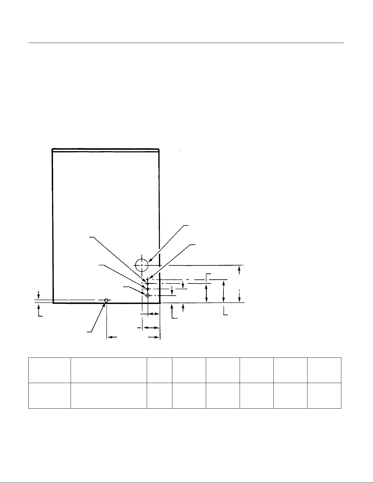
FOR THE INSTALLER: Specifications
This ice maker-dispenser is designed to be
mounted on a machine stand, or a countertop.
Before beginning the installation, check that all the
materials and kits required are available at the
installation location.
Scotsman Ice Systems are designed and
manufactured with the highest regard for safety
and performance. They meet or exceed the
standards of U.L., N.S.F., and C.S.A.
Scotsman assumes no liability or responsibility of
any kind for products manufactured by Scotsman
that have been altered in any way, including the
use of any parts and/or other components not
specifically approved by Scotsman.
Scotsman reserves the right to make design
changes and/or improvements at any time.
Specifications and designs are subject to change
without notice.
Water Limitations:
An ice machine is a food manufacturing plant; it
takes in a raw material, water, and turns it into a
food product, ice. The purity of the water is very
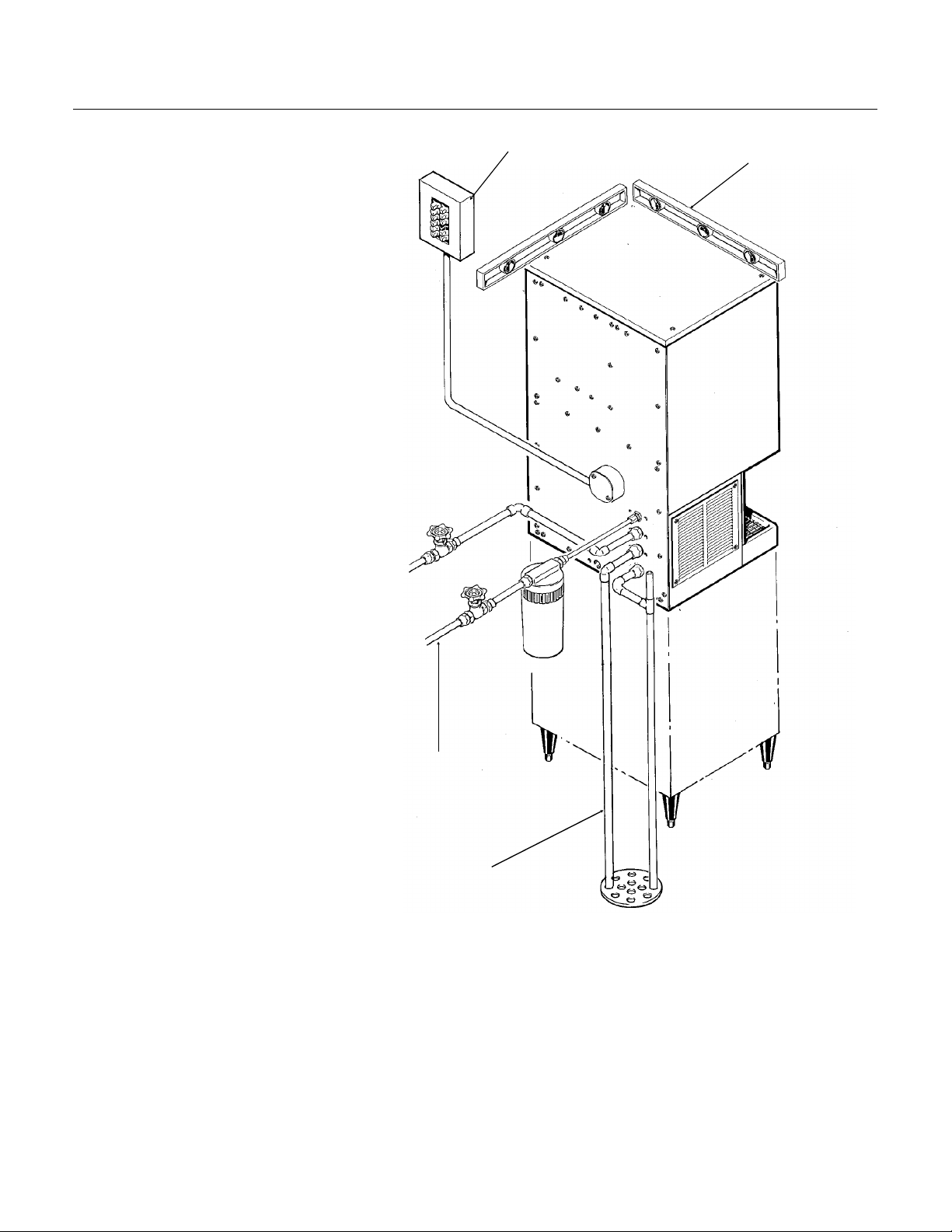
BACK VIEW
important in obtaining pure ice
and in maximizing product life.
General recommendations
are:
1. Filter the water used to
produce ice.
2. Check with a water
treatment specialist for a
water test, and any
recommendations regarding
filters and treatment.
Electrical Junction
Box
3/8" Flare
Water Inlet
6.63"
12.5"
7.93"
Cond. Drain
.75"
1/2" FPT
(W/C)
3/4" FPT
Drain
3/4 FPT
Drain
4.63"
3.84"
2.63"
5.59"
17.59"
SPECIFCATIONS
Model
Number
ND750AE-1
ND750WE-1
Dimensions
(w/o stand)
H" x W" X D"
45.74" x 35.18" x 29.26"
same
Ice
Type
Nugget
same
Condenser
Type
Air
Water
Bin
Capacity
110 lbs.
same
Minimum
Circuit
Ampacity+
19.8
18.4
+ Minimum Circuit Ampacity is used to determine wire size and type per National Electric Code.
Maximum
Fuse
Size
30
30
January, 1989
Page 2
Page 3
FOR THE INSTALLER
ND750
Location
This ice system is designed to be installed indoors,
in a controlled environment.
Minimum Maximum
0
Air Temp 50
Water Temp 40
Water Pressure 20 psi 80 psi
Voltage 104 126
Operating the machine oustide of the above
limitations, or outdoors, is potentially damaging to
the machine; also it is misuse of the machine
which may void the warranty.
Service Limitations
Do not install in a location where the top of the
machine is within 6" of a fixed ceiling. Air cooled
models require a minimum of 6 inches to the left
and right of the machine for air circulation. It is
important that the machine be installed in a
location where it has enough space above and
behind it for service.
After uncrating and inspection, the unit is ready for
installation.
Machine Stand Installation
Tip the stand on it’s back and install the legs,
return the stand to the upright position. Adjust leg
levelers so that the stand does not “rock”.
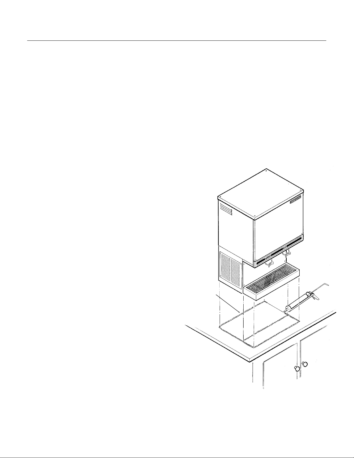
Counter Top or Machine Stand Installation
The base of the icemaker-dispenser must be
sealed to the object it rests upon. Food grade
silastic sealant such as Scotsman part number
19-0529-01 is recommended.
Place a bead of the sealant on the machine stand
or counter top to match the outside edge of the
cabinet base and sink.
The icemaker-dispenser is heavy: use of a
mechanical hoist is recommended to lift it to the
height required to install it.
The DMS machine stand has holes in the top that
match up with threaded holes in the base of the
machine. Secure the machine stand to the base
with 4 5/16" bolts.
F. 1000F.
0
F. 1000F.
In both counter top and machine stand
installations, wipe off and neatly smooth any
excess sealant. Level the machine stand and
cabinet.
Unpack and install the sink brackets. Fit the sink
assembly onto the two sink brackets, and press
onto the bead of sealant. Wipe off and neatly
smooth any excess sealant from under the sink
edge. Connect the sink drain to the dispenser
drain system.
SEAL
ICEMAKER-
DISPENSER TO
THE COUNTER
TOP OR
MACHINE STAND
January, 1989
Page 3
Page 4
ND750
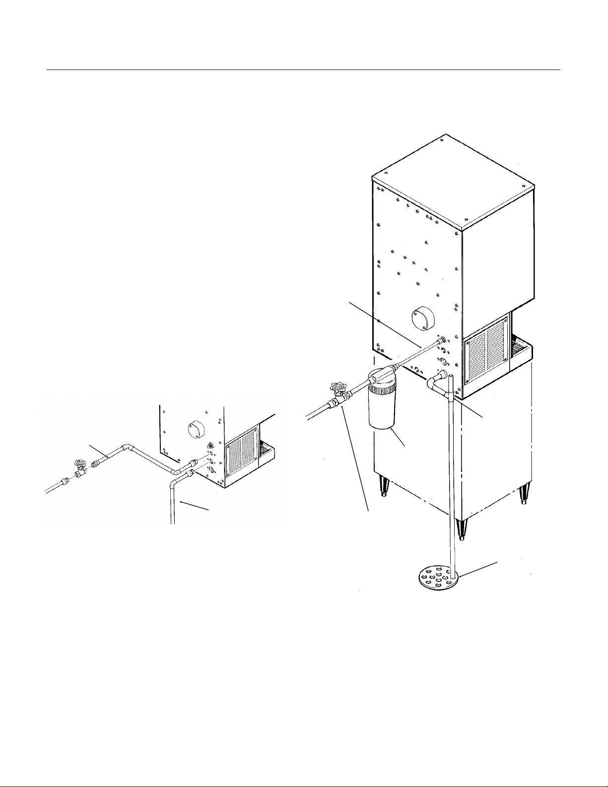
FOR THE PLUMBER
CONFORM TO ALL APPLICABLE CODES
Water Inlet
Air Cooled Models: The recommended water
supply is clean, cold water. Use 3/8" O.D. copper
tubing, connect to the 3/8" male flare at the back
of the cabinet. Install a hand valve near the
machine to control the water supply.
Water Treatment: In most areas, a water filter of
some type will be useful. In areas where the water
is highly concentrated with minerals the water
should be tested by a water treatment specialist,
and the recommendations of the specialist
regarding filtration and/or treatment should be
followed.
Water Cooled Models: A separate 3/8" O.D.
copper line is recommended, with a separate
hand valve to control it. It is connected to a 3/8"
FPT condenser inlet at the back of the cabinet.
The water pressure to all lines must always be
above 20 psig, and below 120 psig.
INLET WATER
Drains
Air Cooled Models: There is one 3/4" FPT drain
WATER COOLED
CONDENSER
WATER INLET
CONDENSER
DRAIN
at the back of the cabinet, the drain line is of the
gravity type, and 1/4 inch per foot fall is an
acceptable pitch for the drain tubing. There
should be a vent at the highest point of the drain
line, and the ideal drain receptacle would be a
trapped and vented floor drain. Use only 3/4" rigid
tubing.
Water Cooled Models: In addition to the above
mentioned drain, a separate condenser drain must
be installed. Connect it to the 1/2" condenser drain
connection at the back of the cabinet.
VENTED
DRAIN
OPTIONAL
WATER
FILTER
SHUT OFF VALVE
FLOOR DRAIN
January, 1989
Page 4
Page 5
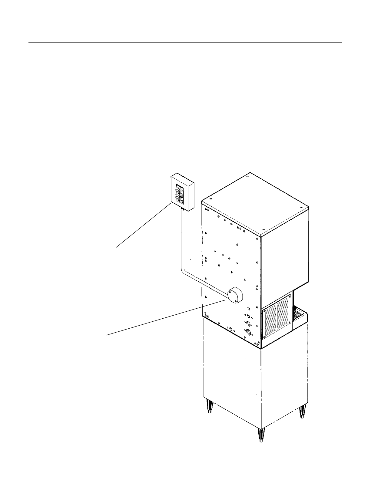
FOR THE ELECTRICIAN
CONFORM TO ALL APPLICABLE CODES
The electrical power to the unit is supplied through
the junction box at the rear of the machine.
Check the nameplate (located on the back panel)
for the voltage requirements, and for the minimum
circuit ampacity. The machine requires a solid
chassis to earth ground wire.
The ice maker should be connected to its own
electrical circuit so it would be individually fused.
Voltage variation must remain within design
limitations, even under starting conditions.
All external wiring must conform to national,
state, and local electrical codes. The use of a
licensed electrician is required to perform the
electrical installation.
ND750
POWER SUPPLY
ELECTRICAL
CONNECTION
January, 1989
Page 5
Page 6
ND750
FOR THE INSTALLER: Final Check List
1. Is the icemaker-dispenser installed
indoors, in a location where the air and
water temperatures are controlled, and
where they do not go beyond design
limitations?
2. is there an electrical service
disconnect within sight of the installed
machine? Is the machine on a separate
circuit? Has the voltage been checked
and compared to nameplate
requirements?
3. Have all of the plumbing connections
been made and checked for leaks?
4. Has the machine been leveled?
5. Is there a minimum of 6 inches of
clearance at the left and right sides of an
air cooled machine?
ELECTRICAL?
LEVELED?
6. Is there a minimum of 6 inches of
clearance at the top and back of the
machine for service and utility
connections?
7. Is there a water shut off valve
installed near the machine?
8. Have all of the shipping blocks been
removed?
WATER INLET?
DRAINS?
January, 1989
Page 6
Page 7

INITIAL START UP
Pre Start Inspection
1. Remove the two front panels.
2. Check that all shipping blocks have been
removed.
3. Remove any and all packing tape (check inside
the storage bin).
4. Inspect the interior of the machine for loose
screws or wires. Check that no refrigerant lines are
rubbing each other. Check that the fan blade on air
cooled models turns freely.
5. Check that the machine is installed correctly
according to the final check list.
Start Up
1. Go through the pre start inspection.
2. Open the water hand valve, observe that water
enters the water reservoir, fills the tube from the
reservoir to the evaporator and then shuts off.
Check for leaks.
3. Switch the master switch on. The electrical start
up sequence is now on automatic:
A. There will be a short (15 second) delay before
the gearmotor starts.
B. After the gearmotor starts, the compressor will
start.
4. On air cooled models, warm air will begin to flow
from the condenser. Water cooled models will
begin to discharge warm water down the drain.
5. The unit should soon be making ice. If desired,
the low side pressure may be checked: it should
be 30 PSIG + or - 4 PSIG.
The air cooled discharge pressure will depend
upon air and water temperatures, but should be
between 200 PSIG and 280 PSIG.
Water cooled discharge pressure should be about
220 PSIG. If needed, adjust the water regulating
valve.
The above numbers are for new, clean machines.
Field values may be somewhat higher or lower.
6. There are no adjustments to make, so replace
the panels.
ND750
turning a knob, the length of time the unit
dispenses when the glass filler lever is pushed
(and the amount of ice dispensed) is adjusted.
8. Switch off the icemaker-dispenser, remove the
top panel and the top of the ice storage bin.
Sanitize the interior of the ice storage bin by wiping
it with a mixture of 1 ounce of household bleach to
1 gallon of water, allow to air dry. Replace all
covers and panels. Switch the icemaker-dispenser
back on.
9. Give the owner/user the service manual, instruct
him/her in the operation and maintenance
requirements of the unit. Make sure they know
who to call for service.
10. Fill out the warranty registration card, and mail
it in to Scotsman.
11. Fill out the field Quality Audit form, and mail it
to Scotsman.
7. Check ice dispensing by pushing in on the glass
filler lever. Ice dispenses are portion controlled; by
January, 1989
Page 7
Page 8
ND750
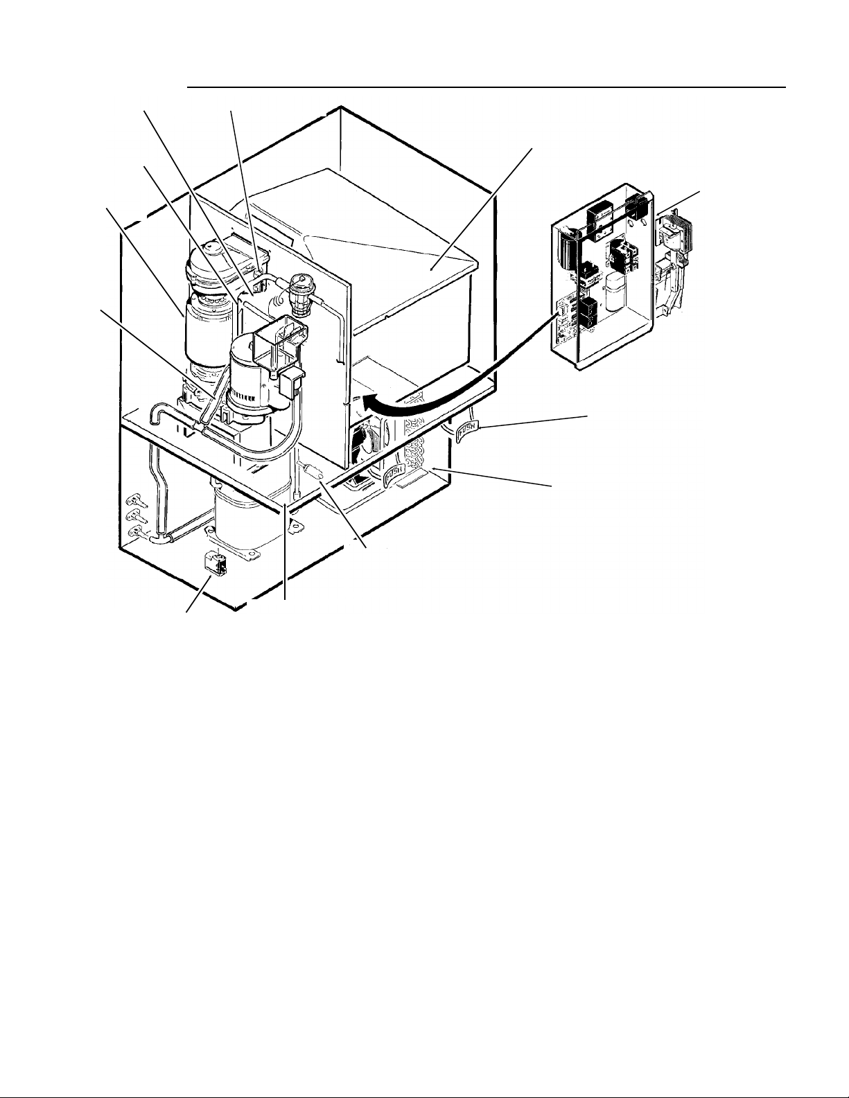
COMPONENT DESCRIPTION
RESERVOIR
RESERVOIR
WATER
WATER
LEVEL
LEVEL
SENSOR
SENSOR
EVAPORATOR
EVAPORATOR
DRAIN
DRAIN
TUBE
TUBE
ICE LEVEL SENSOR
ICE LEVEL SENSOR
ICE STORAGE BIN
ICE STORAGE BIN
GLASS FILLER
GLASS FILLER
CONTROL BOX
CONTROL BOX
HI
HI
PRESSURE
PRESSURE
CUT OUT
CUT OUT
PORTION
LOW
LOW
PRESSURE
PRESSURE
CUT OUT
CUT OUT
PORTION
CONTROL KNOB
CONTROL KNOB
Control Box: Contains the electrical controls that
operate the machine.
High Pressure Cut Out Switch: A manual reset
switch sensing the high side refrigeration pressure.
It is set to shut the machine off, and illuminate the
reset switch light if the discharge pressure should
ever exceed 450 psig.
Evaporator: A vertical stainless steel tube,
refrigerated, and water filled. In it there is a
stainless steel auger.
Reservoir: Float operated, it maintains the water
level in the evaporator at a constant level, it also
contains the water level sensor.
Water Level Sensor: Senses if there is water in
the reservoir to make ice out of. Will shut the
machine off it there is none.
Ice Level Sensor: An electronic ‘‘eye’’, it senses
the presence of ice in the bottom of the ice
discharge chute. Operates to turn the ice machine
CONDENSER
CONDENSER
on and off automatically as the level of ice in the
bin changes.
Drain Tube: When uncapped and lowered, drains
the evaporator.
Condenser: Air or water cooled, where the heat
removed in ice making is discharged.
Ice Storage Bin Assembly: A plastic lined,
insulated cylinder that receives, stores and
dispenses the ice. Fresh ice enters at the top, and
when the bin is full enough the ice will be between
the ice level sensors, and the icemaking will stop.
Ice is dispensed through a chute at the bottom
front when the agitator assembly sweeps the ice
through the chute.
Glass Filler Lever: Pushing in on this lever
causes the ice dispensing cycle to occur.
Portion Control Knob: Turning this knob adjusts
the length of time of dispense.
January, 1989
Page 8
Page 9
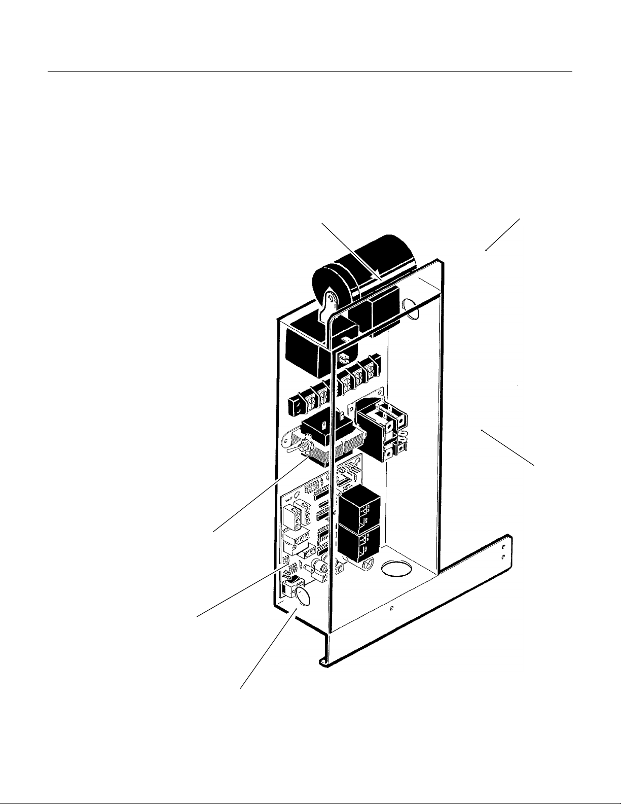
COMPONENT DESCRIPTION: Control Box
POTENTIAL RELAY
CONTACTOR
Contactor: A definite purpose contactor
connecting the compressor to the power supply.
Circuit Board: Controlling the ice machine
through sensors and relays. The sensors are for
ice level and water level. The relays are for the
gear motor (with a built in time delay to clear the
evaporator of ice when the unit turns off) and for
the compressor. The reset switch is mounted on
the circuit board.
On/Off Switch: Manual control for the machine.
Transformer: Supplies low voltage to the circuit
board.
Potential Relay: The compressor
start relay.
Reset Switch: Part of Circuit
Board, manual reset. Lights up
when unit shuts off from: ice
discharge chute being overfilled
(opening the microswitch at the
top of the chute); low or high
pressure switches opening.
Portion Control Module: Controls
the amount of time the dipensing
drive motor is on. The time is
varied by adjusting the portion
control knob.
PORTION CONTROL
ND750
TRANSFORMER
CIRCUIT BOARD
RESET SWITCH
January, 1989
Page 9
Page 10

ND750
COMPONENT DESCRIPTION
Evaporator: A refrigerated vertical tube filled with
water and containing a water seal and auger.
Auger: A solid stainless steel double spiral auger,
it pushes the ice crystals up to the top of the
evaporator.
Water Seal: A two part "face" seal, the top half
rotating with the auger, the bottom half stationary,
the sealing action being where the two seal "faces"
meet.
Ice Sweep: A plastic cap with "fingers". It revolves
with the auger to "sweep" the ice into the ice chute.
Breaker: Where the ice is compressed and much
of the extra water is squeezed out of it before it is
discharged into the bin.
SPOUT SWITCH
ICE CHUTE
Motor: A permanent split capacitor motor that
drives the gear reducer.
Thrust Bearing: As the ice is pushed up the
evaporator, the auger is thrust down, and pressure
from the auger thrust is taken up by this bearing.
ICE SWEEP
BEARING
BREAKER
AUGER
WATER SEAL
WATER INLET
GEAR MOTOR
EVAPORATOR
January, 1989
Page 10
Page 11

ELECTRICAL SEQUENCE
ND750
Refer the wiring diagram as needed.
If the machine is switched off at the master switch,
but is otherwise ready to go, switching the master
switch to on does the following:
••The bin empty light on the circuit board goes on
••
There is a 15 second delay
••If there is enough water in the reservoir, the
circuit board will allow the machine to start up.
Start up consists of:
••The compressor relay and auger motor relay
become energized, connecting power to the
windings of the auger motor.
••The auger motor starts, and the centrifugal
switch closes, connecting power to the
compressor contactor coil.
••The contactor is energized, connecting power
to the compressor, and the compressor starts.
••As ice goes past the ice level sensors, the bin
empty light will stay on, and the machine will
continue to run, unless the ice stays between
the sensors for more than 15 seconds (bin full).
At that point, the bin empty light goes out, and
the machine shuts down.
Shut Down consists of:
••The compressor relay opens.
••The compressor contactor opens
••The compressor stops
••The auger motor is run by the circuit board for
2.5 more minutes, clearing out ice in the
evaporator, and then
••The auger motor relay opens, and the auger
motor stops.
If the ice level sensor is clear (bin empty) for more
than 15 seconds, the machine will start up again.
Another purpose of the circuit board is to turn the
machine off if there is not enough water in the
machine.
••When the water level in the reservoir falls
below the water level sensor, the machine will
“shut down”
••If the high pressure control (cut out switch)
opens, the machine will stop immediately
(through the relays on the circuit board) and
cause the reset switch on the circuit board to
light up. It must be manually reset at the
control and at the reset switch on the circuit
board.
••If the low pressure control (cut out switch)
opens, the machine will stop immediately
(through the relays on the circuit board) and
cause the reset switch on the circuit board to
light up. It must be manually reset at the
control and at the reset switch on the circuit
board.
••If the spout switch opens, the machine will stop
immediately (through the relays on the circuit
board) and cause the reset switch on the circuit
board to light up. After it re-closes the reset
switch on the circuit board must be manually
reset.
••The master switch is the manual control for the
complete machine, but it is not a service
disconnect.
Ice Vending
••When the glass filler lever is pushed in the vend
switch closes. That energizes the ice chute
door solenoid, and the portion control module,
which, depending upon the setting of the
portion control knob, will power the agitator
drive motor for a set length of time.
••Holding the glass filler lever in will not cause
additional dispensing, unless the portion control
is set for continious dispensing. Releasing and
re-pushing the glass filler lever will repeat the
dispense cycle.
••When the water refills the reservoir, the
machine will start up again.
Separate from the circuit board:
January, 1989
Page 11
Page 12

ND750
OPERATION: Water
ADJUSTMENT
OF THE
WATER
RESERVOIR
Water enters the machine through the 3/8" male
flare at the rear of the cabinet, goes to a strainer
and then to the water reservoir which it enters
through the float valve. The water then goes out
the bottom of the reservoir tank to the bottom of
the evaporator.
Reservoir overflow, evaporator condensation and
water in the sink are all routed to the drain. Water
cooled models have a separate water circuit for
the cooling water: it enters the fitting at the rear,
goes to the water regulating valve, then to the
water cooled condenser and down the drain.
The water dispensing station adds an additional
water circuit. When the water station glass filler
lever is pushed, a switch closes a circuit to an
electric water valve, and water is dispensed.
RESERVOIR
RESERVOIR DRAIN
WATER INLET
WATER LEVEL
DRAIN TUBE
WATER SCHEMATIC
January, 1989
Page 12
Page 13

OPERATION: Refrigeration
SUCTION LINE
THERMOSTAT IC
EXPANSION VALVE
ND750
Beginnin g at the comp re sso r , th e refri g erant 502 is
compressed into a high temperature gas. The
discharge lin e directs th is gas to the co nden ser. At
the condenser (air or wat er coo led ) the gas is
cooled by eit he r ai r or wat er and it the n co nden ses
into a liquid. This high pressu re liquid the n goes
through the liquid line to the expansion valve. The
thermostatic expansion valve meters liquid
refrigerant into the evaporator, the volume of liquid
refrigerant depending upon the temperature of the
evaporator; warmer evaporators get more
re fr igerant and cold er evaporators get l es s.
REFRIGERATION SCHEMATIC
(AIR COOLED SHOWN)
LIQUID LINE
At the eva po rato r, th e refri g eran t en te rs a n are a of
relatively low pres sure , whe re it can easily “boil off”
or evaporate. As it evaporates, it absorbs heat
from the evaporator and wha tever is in con tact
with it (such as the water inside it). After the
evaporator, the refrigerant, now a low pressure
vapor, goes through the su ctio n line back to
compressor, where the cyc le is repe ated .
CONDENSER
FAN MOTOR
DISCHARGE
HI PRESSURE
CUT OUT
LINE
EVAPORATOR
COMPRESSO R
January, 1989
Page 13
Page 14

DOOR
SOLENOID
ICE CHUTE
DOOR
ICE CHUTE
ND750
OPERATION: Ice Vending
When the ice dispensing glass filler lever is
pushed, an electrical circuit is made to the ice
chute door solenoid causing the ice chute door to
open. At the same time power is connected to the
portion control module in the control box. That
module will energize the agitator drive motor for a
certain length of time, depending upon the setting
of the portion control knob.
The dispensing takes place when the agitator
sweeps the ice through the ice dispensing chute:
ice will continue to
discharge out this chute as
long as the agitator is
turning. It stops when the
agitator stops.
ICE DISCHARGE CHUTE
STORAGE BIN
AGITATOR
AGITATOR
DRIVE MOTOR
VEND SWITCH
GLASS FILLER
LEVER
SINK
January, 1989
Page 14
Page 15

ND750
MAINTENANCE AND CLEANING
//////////////////////////////////////////////////////////////////////////////////////////////////////////////////////////////////////////////////////////
A Scotsman Ice System represents a sizable investment of time and money in any company’s
business. In order to receive the best return for that investment, it MUST receive periodic
maintenance.
It is the USER’S RESPONSIBILITY to see that the unit is properly maintained. It is always
preferable, and less costly in the long run, to avoid possible down time by keeping it clean;
adjusting it as needed; and by replacing worn parts before they can cause failure. The following
is a list of recommended maintenance that will help keep the machine running with a minimum of
problems.
Maintenance and Cleaning should be scheduled at a minimum of twice per year.
///////////////////////////////////////////////////////////////////////////////////////////////////////////////////////////////////////////////////////////
/////////////////////////////WARNING///////////////////////////
Electrical power will be ON when doing in
place cleaning. Switch it OFF before
completing the cleaning procedures.
///////////////////////////////////////////////////////////////////////////
ICEMAKING SYSTEM: In place cleaning
1. Check and clean any water treatment devices, if
any are installed.
2. Remove screws and remove the upper front
panel.
3. Move the ON-OFF switch to OFF.
4. Remove the cover to the ice storage bin, and
remove the ice.
5. Remove the cover to the water reservoir and
block the float up.
6. Drain the water reservoir and freezer assembly
using the drain tube attached to the freezer water
inlet. Return the drain tube to its normal upright
position and replace the end cap.
///////////////////////////WARNING/////////////////////////////
Scotsman Ice Machine Cleaner contains
Phosphoric and Hydroxyacetic acids. These
compounds are corrosive and may cause
burns. If swallowed, DO NOT induce vomiting.
Give large amounts of water or milk. Call
Physician immediately. In case of external
contact, flush with water. KEEP OUT OF THE
REACH OF CHILDREN.
//////////////////////////////////////////////////////////////////////////
7. Prepare the cleaning solution: Mix eight ounces
of Scotsman Ice Machine Cleaner with three
quarts of hot water. The water should be between
90-115 degrees F.
8. Slowly pour the cleaning solution into the water
reservoir until it is full. Wait 15 minutes, then
switch the master switch to ON.
9. As the ice maker begins to use water from the
reservoir, continue to add more cleaning solution
to maintain a full reservoir.
10. After all of the cleaning solution has been
added to the reservoir, and the reservoir is nearly
empty, switch the master switch to OFF.
11. After draining the reservoir, as in step 6, wash
and rinse the water reservoir.
12. Remove the block from the float in the water
reservoir.
13. Switch the master switch to ON
14. Continue ice making for at least 15 minutes, to
flush out any cleaning solution. Check ice for acid
taste - continue icemaking until ice tastes sweet.
//////////////////////////////WARNING//////////////////////////
DO NOT USE any ice produced from the
cleaning solution.
Be sure no ice remains in the bin.
//////////////////////////////////////////////////////////////////////////
15. Remove all ice from the storage bin.
16. Add warm water to the ice storage bin and
thoroughly wash and rinse all surfaces within the
bin.
17. Sanitize the bin interior with an approved
sanitizer using the directions for that sanitizer.
18. Replace the ice storage bin cover, and the
front panel.
January, 1989
Page 15
Page 16

ND750
MAINTENANCE AND CLEANING
///////////////////////////WARNING/////////////////////////////
Disconnect electrical power before beginning.
//////////////////////////////////////////////////////////////////////////
1. The ice machine senses water level by a probe
located in the water reservoir. At least twice a
year, the probe should be removed from the
reservoir, and the tip wiped clean of mineral
buildup.
2. The bin control uses devices that sense light,
therefore they must be kept clean enough so that
SLIDE SENSORS
UP TO REMOVE
PROBE
RESERVOIR
CLEAN THE TIP
//////////////////////////////
CAUTION: THE
TIP IS MADE OF
GLASS;
/////////////////////////////
they can “see”. At least twice a year, remove the
bin control sensors from the grommets in the ice
chute, and wipe them clean.
3. The bearing in the breaker should also be
checked at least two times per year.
A. Check the bearing by:
••removing the ice chute cover
••unscrewing the ice sweep
••removing the water shed
••using a spanner wrench and unscrewing the
breaker cover.
••unscrewing the auger stud
Inspect the assembly, looking for wear.
See Removal and Replacement to replace
bearing or seals. Reverse to reassemble.
4. Check and tighten all bolts and screws.
ICE SWEEP
January, 1989
Page 16
Page 17

MAINTENANCE AND CLEANING: Auger
BREAKER AND
AUGER ASSEMBLY
In some areas, the water supply to the ice maker
will contain a high concentration of minerals, and
that will result in an evaporator and auger
becoming coated with these minerals, requiring a
more frequent removal than twice per year. If in
doubt about the condition of the evaporator and
auger, the auger can be removed so the parts can
be inspected.
Note: Water filters can filter out suspended solids,
but not dissolved solids. “Soft” water may not be
the complete answer. Check with a water
treatment specialist regarding water treatment.
For more information on removal of these
parts, see REMOVAL AND REPLACEMENT.
/////////////////////////////WARNING///////////////////////////
Disconnect electrical power, and shut off the
water supply.
Use care when removing the auger, it has
sharp edges.
//////////////////////////////////////////////////////////////////////////
1. To remove the auger, remove the front and top
panels.
2. Drain evaporator using drain hose.
3. Remove 3 hex studs holding ice chute cover to
ice chute, and remove cover.
4. Unscrew and remove ice sweep.
5. Loosen band clamp under ice chute, and
remove ice chute from evaporator.
6. Remove 4 allen screws holding breaker to
evaporator.
7. Pull up to remove auger.
After the auger has been removed, allow the auger
to dry: if the auger is not bright and shiny, it must
be cleaned.
Clean the auger and evaporator as required. DO
NOT HONE THE EVAPORATOR.
8. Replace the water seal.
9. Reverse to reassemble.
ND750
January, 1989
Page 17
Page 18

ND750
SERVICE DIAGNOSIS: Condition - No Ice Being Produced
STATUS:
A. Check: Voltage to the unit, restore it if there is none. Compare to the nameplate.
B. Check: The master switch, switch ON if off.
C. Check: The 3 reset switches, (circuit board, high and low pressure): depress and release each
switch. If the still does not start, check: the spout switch; the high and the low side pressures.
D. Check the low pressure cut out, if closed, go to E; if it is open, it could be due to:
ICE MAKER DOES NOT OPERATE
••Low refrigerant charge
••The auger not turning
••Restricted system
••TXV not opening
1. Check the low side pressure, the low pressure cut out opens at pressure below 4 psig.
If open, reset and:
a. Check if the auger is turning, if it is not, remove the gearbox and:
Check for internal damage, repair and replace in the machine.
b. Check for low charge, add some refrigerant, if the unit will operate,(normal
low side pressure being about 30 psig) stop and look for a leak, repair, replace the
drier, evacuate, and weigh in the nameplate charge. If, with added charge, the unit
does not operate:
Check for a restricted system, replace the drier, evacuate, and weigh in a
nameplate charge.
Check for a Thermostatic Expansion Valve that does not open, if defective,
replace it. Replace the drier, evacuate, and weigh in the nameplate charge.
E. Check the high pressure cut out, if closed, go to F; if open:
1.The pressure control opens at 450 psig. Check the high side pressure, reset the control,
and observe: on water cooled, that water soon begins to flow from the condenser drain;
or, on air cooled, that the fan is forcing air through the condenser. If the unit trips out on
pressures below 450 psig, replace the control. If the pressures rise above the trip out
point, and the unit shuts down:
a. Check for adequate water flow on water cooled, if adequate, clean the interior
of the condenser. If the pressures are still too high replace the water regulating valve.
b. Check for adequate air flow on air cooled. Clean the condenser and (if used) the
filter. If the air flow is poor because of the installation, advise the user that the unit
should be moved, or the air around it kept cooler.
Check the fan motor for tight bearings and proper rotation.
Check that the fan blades are clean, and the fan secure to the fan motor shaft.
F. Check the spout switch. It opens from excess pressure of ice inside the ice chute: this should only
happen when the machine does not shut off when the ice storage bin is full. This switch will reset
when the ice melts, but the machine will not restart until the reset switch on the circuit board is
pressed.
G. Check the water level in the reservoir. The machine will not run if there is not enough water in the
reservoir.
January, 1989
Page 18
Page 19

1. Restore/adjust water level. See the next step.
SERVICE DIAGNOSIS: Condition - No Ice Being Produced
ND750
STATUS:
ICE MAKER DOES NOT OPERATE
H. Check: The gear motor, if it will not run, the compressor will not run. If no power to it:
Check: The indicator lights on the circuit board, the bin empty light should be ON, the no water light
should be OFF .
1. If the bin empty and no water lights are off, check the transformer.
a. Transformer “load” side should have 12 to 15 volts. If not, check the “line” side. The line
side should have between 110-120 volts. If the line side has the correct voltage and the
load side does not, replace the transformer.
2. If the transformer is good, and the bin empty light is OFF, check the ice level sensors.
a. Remove sensors by pulling them out of the ice chute grommets. Visually inspect them,
clean if needed.
b. Look through the ice chute “eye” hole for something blocking the ice chute.
c. If the unit still does not run, replace the ice level sensors.
d. If the bin empty light is still OFF, check the circuit board.
1. Unplug “opto trans” and “LED” connectors from the circuit board.
2. Plug “opto trans” and “LED” connectors from the Scotsman Electronic Control
Testor Model NM1 into the circiut board.
a.Move the “bin full” switch on the tester to the full position. The bin full light
on the tester should be ON, if not, replace the circuit board.
If the bin full light on the tester is ON, move the tester switch to “bin empty”
the light on the tester should go OFF and the bin empty light on the circuit
board should go ON. If not, replace the circuit board. If it does as above,
and the machine still does not run, replace the ice level sensors.
3. If the transformer is fine, and the “no water” light is ON, check the water level sensor.
a. Check the water level in the reservoir, restore if low. If the water level is ok:
b. Remove the water level sensor from the reservoir and clean the tip if dirty.
CAUTION: THE TIP IS MADE OF GLASS
c. Replace the water level sensor. If the no water light is still on, check that the
"water sen" plug is firmly plugged into the circuit board.
d. If the no water light is still on,
1. Unplug the “water sen” connector from the circuit board.
2. Plug “water sen” connector from the Scotsman Electronic Control tester into
the circuit board.
a. Move the water switch on the tester to “no water” and the no water light
on the circuit board should go on. If not, replace the board.
b. Move the water switch to the “water” position, the no water light should
go off, if not, replace the circuit board.
c. If after the above, the machine still will not run, replace the water level
sensor
MORE INFORMATION ON THE TESTER MAY BE FOUND AT THE BACK OF THE MANUAL.
January, 1989
Page 19
Page 20

ND750
SERVICE DIAGNOSIS: Condition - No Ice Being Produced
STATUS:
A. Check the compressor relay.
The relay is on the circuit board, if it does not supply power to the contactor coil, the
compressor will not run.
1. Check for power at the contactor coil, if none:
2. Check the contactor coil. If the coil is open, replace the contactor.
3. Check the auger drive motor centrifugal switch. If, when the drive motor is running,
contact 4 (black wire removed) has no power, and all of the above switches have been
checked, replace the centrifugal switch, or the drive motor.
4. If the compressor relay on the circuit board has power on the NO contact, but not on the COM contact,
replace the circuit board
B. Check the compressor
1. Check the compressor start relay.
2. Check the start capacitor.
3. Check the windings of the compressor for open windings or shorts to ground.
Replace those items found defective.
GEARMOTOR OPERATES, COMPRESSOR DOES NOT
a. Check for power at the compressor relay at the circuit board.
If there is power at the relay, but none at the contactor coil,
Check for an open wire between the relay and the contactor.
January, 1989
Page 20
Page 21

SERVICE DIAGNOSIS: Condition - Low Ice Production
ND750
STATUS:
A. Check the air cooled condenser for dirt. Clean as required. Check the head pressure on water
cooled. Adjust as required. If the head pressure is very high:
1. Air cooled. Check for high air temperatures, or restrictive air flow. Correct as needed.
3. The refrigerant may contain non condensable gases, purge, evacuate, and recharge per
nameplate.
B. Check the evaporator
1. Clean the evaporator, the mineral build up will adversely affect the ice machines production.
3. Check the low side pressure; normal is about 30 psig. If low, assume a refrigerant leak,
EVERYTHING IS OPERATING
2. Water cooled. Check for high water temperatures, or low water pressure.
Correct as needed.
2. Check the evaporator for water leaks, replace the water seal if found to be leaking.
locate, repair and recharge.
If no leak, the TXV may be restricted, defective or not adjusted properly. If needed,
replace the TXV, evacuate, and recharge per nameplate.
4. Check the insulation on the evaporator. It should be dry, with no wet spots or frost.
If the insulation has failed: replace the evaporator or add extra insulation in the form
C. Check the compressor.
b. if the amp draw is normal, pinch off the suction line to check the pull down capability
of the compressor. The compressor should pull down to 25 inches of vacuum and hold
of foam tape to the evaporator.
1. The compressor may be inefficient.
a. Check the amp draw, if low change the compressor.
there for three to five minutes.
January, 1989
Page 21
Page 22

.
If no ice
ND750
SERVICE DIAGNOSIS: Condition - Poor or No Ice Dispensing
STATUS:
A. Check for ice in the bin, if no ice, check the ice making system.
If the ice making system is normal, the demand for ice may exceed the quantity the icemaker cam produce
Check with the user on ice usage: advise the user that another machine may be needed.
B. Check for motion in the agitator when the glass filler lever is pushed, if no motion: Check the vend
switch, if it does not close when the glass filler lever is pushed, replace the switch.
If the vend switch does close, check for voltage at the agitator drive motor. If there is voltage, and the
agitator motor output shaft does not turn, replace the agitator gear motor assembly.
C. Check that the ice dispensing door opens when the glass filler lever is pushed. If not, check the
vend switch. If the vend switch is good, check the door solenoid.
If the agitator moves when it is supposed to, and there is ice, the dispensing cycle should be fine.
is dispensed, check for an obstruction in the ice chute.
D. No portion control.
1. Continuous dispensing when the glass filler lever is pushed in: Check for an open potentiometer (portion
control). If open, replace it.
If it is not open, replace the portion control module in the control box.
2. Very short dispensing: Check for a shorted potentiometer (portion control). If shorted, replace it.
If it is not shorted, replace the portion control module in the control box.
There is power to the unit, but no ice is dispensed
January, 1989
Page 22
Page 23

REMOVAL AND REPLACEMENT
SLIDE HOUSINGS UP
TO REMOVE
ND750
WATER RESERVOIR
1. Shut off the water supply to the icemaker.
2. Remove front pane l and reservo ir cove r.
3. To remove float only, pry the moun tin g flang es
apart enough to lif t one flo at pivot pin out of the
flange hole, and pull float up and out of the
reservoir.
4. To remove reservoir, dis con ne ct water inle t
compression fitt ing at reservoir inle t.
5. Remove drain hose from reservoir.
6. Remove evaporator inlet hose from reservoir.
7. Remove mounting screws from rese rvoir
bracket, and remove reservoir from icemaker.
8. Reverse to reassemble.
BIN CONTROLS (Ice Level Sensors)
1. Disconnect electrical power.
2. Remove front panel.
3. Remove control box cover.
4. Locate bin top, in front of and behind it are two
rubber bin control gro mmet s.
5. Pull each bin contro l out , and in the con tro l box,
disconnect the electrical lea ds connecting the bin
control to the circuit board.
6. Reverse to reassemble, be certain that the bin
controls are alig ne d so that th e ice lev el sen so rs
are visible (cent ered ) t hrou gh the hole s in the ice
chut e.
FLO AT
MOUNTING
FLANGE
January, 1989
Page 23
Page 24

BEARING
STEPS 5-C
AND 6
ND750
REMOVAL AND REPLACEMENT: Bearing And Breaker
Note: Remov al of the auger, wat er sea l,
evaporator and gearmotor must begin at the top of
the assembly.
To Remove the Breaker Bearing Assembly:
//////////////////////////////WARNING //////////////////////////
Disconnect the electrical power to the machine
at the building source BEFORE proce eding
with any repair.
//////////////////////////////////////////////////////////////////////////
1. Remove panels and disconnec t ele ctrica l power.
2. Unscrew three stu ds and remo ve ice chut e
cover.
3. Unscrew and remove ice sweep.
4. Remove insulation halv es fro m out side of ice
chute, loosen band clamp under ice chute , lift up
and remove ice chut e.
5. The breaker may be removed from the auger
and evaporator without disturb ing the auger.
a. Use spanner wrench and unscrew breaker
cover from breaker (lef t hand thre ads )
b. Unscrew auger stud from top of auger.
c. Unscrew 4 allen head cap screws holding
breaker to eva po ra t or .
d. Lift up, and remove bre aker/bearing assembly
from auger & evapor ator.
6. Service the bearing. Che ck fo r rust, rough spo ts
and da m age.
a. The bearing is presse d into th e
ICE SWEEP
STEP 5-A STEP 5-B
remove the bearin g and replace it an arbor p ress
is ne eded .
b. Replace lower seals be fore installing new
bearing in breaker.
Note: seals must be pres sed in with a tool pu sh ing
against the outer edge only, they will not install by
hand.
Replace parts as required. Re-g reas e bearing with
Scotsman part no. 19-0609-01 bearing grease.
Replace to p sea l, and ch eck the o-rin gs, repla ce if
cut or torn.
7. Revers e to reassemble: sp ecific to ols an d
materials are requ ired to install pro pe rly .
a. Add food grade greas e suc h as Scot sman part
number 19-05 69 -01 to th e sea l area bef ore
installing on the auger.
b. Check the seal to shaft areas for cuts, or rough
spots: none are permitted.
breaker, to
BREAKER
January, 1989
Page 24
Page 25

REMOVAL AND REPLACEMENT
SLIDE HAMMER
PULLER
ND750
To Remove the Auger:
Turn off the wate r to the mach ine , and unclip the
evaporator drain hose, pull it down and drain the
evaporat or int o th e bin or a cont ainer.
//////////////////////////////WARNING // ////////////////////////
Make sure the elect rical po wer is OFF.
//////////////////////////////////////////////////////////////////////////
1. The top panel must be removed.
2. Remove ice chute cov er.
3. Unscrew ice sweep.
4. Loosen band clamp an d remove ice chute body.
5. The auger and breaker/bearing may now be
removed as an assembly.
a. Unscrew 4 allen head cap screws hold ing
breaker to eva po ra t or .
b. Lift up on breaker and remove auger from
evaporat or.
Note: If the auger is stuck, the breaker must be
removed from the auger.
BREAKER/
BEARING/
AUGER
ASSEMBLY
SHARP EDGES!
when wet, but after it is dry it will be seen to be
stained . Scrub the auger with ice machin e cle an er
and ho t wa ter.
////////////////// /////////W A R N ING////////// ////////////////// //
Ice machine clea ne r is an acid. Handle it with
extreme care, keep out of the reach of children.
//////////////////////////////////////////////////////////////////////////
2. The water seal area. Because the auger has
been removed, the wate r seal will hav e to be
replaced. Remove the wate r se al to p half from th e
auger, and inspect the auger for minerals clean as
required.
The breake r may be removed from the auger an d
evaporator without disturb ing the auger.
a. Use spanner wrench and unscrew stainless
breaker cover from breaker (left hand threads)
b. Unscrew auger stud from top of auger.
c. Unscrew 4 allen head cap screws holding
breaker to eva po ra t or .
d. Lift up & remove breaker from evap orat or.
e. If the auger is stuck use a slide hammer type
puller to pull on the auger at the threade d hole.
The size of that hole is 5/8"-18.
Inspect the auger, the critical areas of the auger
are:
1. The auge r body . It s hould be clean and
shining. Sometimes an auger will appear clean
THREAD INTO
AUGER
January, 1989
Page 25
Page 26

ND750
REMOVAL AND REPLACEMENT: W ater Seal
To Remove the Water Seal:
(Assuming all steps to remove the auger have
been performed.)
1. The gearmotor/evaporator assembly will have to
be exposed. (See illustration - next page)
2. Remove the 4 hex head cap screws holding the
evaporator to the gearmoto r asse mbly. Lift the
evaporator up and off of the gearmotor.
3. Remove the snap ring or wire retainer from the
grove under the water seal.
4. Pull or drive out the lower half of the water sea l.
To Replace the Water Seal:
1. Lubricate the water seal with wat er, and push
the water seal in to the bot to m of th e ev aporator
19-0529-01) on the area of the auger where the
water seal is to be mounted.
5. Carefully push the water seal (rubber side
against the auger shoulder and the silastic.)
/////////////////////////////CAUTION///////////////////////////
Do not get any silastic onto the face of the seal.
/////////////////////////////////////////////////////////////////////////
6. Allow the auger and seal to air dry until the
silastic is dry on the surface.
WATER SEAL
RETAINING RING
slightly past th e grove fo r the snap ring .
2. Replace the snap ring and pull the water seal
down against it.
3. The part of the water seal that rota tes wit h the
auger must also be replac ed . Remove the old part
from the auger and clean the mounting area.
4. Place a small bead of food grade silastic se alant
(such as 732 RTV or Scot sman part numb er
FOOD GRADE
SEALANT HERE
7. If the origina l wate r se al was lea kin g, it would be
a good idea to inspect the interior of the gearmotor.
January, 1989
Page 26
Page 27

REMOVAL AND REPLACEMENT
BREAKER
ND750
To Replace the Evapora tor:
(Assuming all the ste ps for remova l of the thrust
bearing, breaker, au ger, an d water sea l have been
perform ed.)
1. Discharge the refrige rant from th e ice maker.
2. Unsweat the refrigerant connections:
a) At the thermostatic expa nsio n valve ou tle t.
//////////////////////////////CAUTION///////////////////////////
Heat sink the TXV body when unsweating or
resweating the adjacent tubing.
//////////////////////////////////////////////////////////////////////////
b) At the suction line at the joint ab out 3" from the
evaporat or.
3. Remove the evaporator.
4. Unsweat the drier from the
liquid line.
5. After installin g a new water
seal in the new evaporator
(see “To Replace the Water
Seal”) sweat in the new
evaporat or at the old tubin g
connect ions.
6. Install an new drier in the
liquid line.
7. Evacuate the system until
dehydrated, then weigh in the
nameplat e ch arge. Check fo r
leaks.
8. Install auger, breaker,
breaker bearing assembly,
and ice discharge chute in
reverse order of dis assembly.
EVAPORATOR
WATER
SEAL
RETAINING RING
DRIP PAN
To Reassemble the Evaporator an d Auger
1. After the gearmot or has bee n ins pecte d, fas te n
the evaporat or to the gear mot or, be sure that th e
number of shims indicated on the gear case cover
is in place between the gearcas e cov er and the
drip pan gasket. Torqu e th e bolts to 110 inch
pounds .
2. Lower the auger into the evaporator barrel,
slightly turning it to match up with the drive end.
Do Not Drop Into the Evap ora to r.
3. Complete the reassembly by reversing the
disassemb ly f or th e brea ker & thrust bearing
assembly.
ICE SWEEP
BREAKER
BEARING
AUGER
January, 1989
Page 27
Page 28

ND750
TO REMOVE AND REPAIR THE GEARMOTOR ASSEMBLY
(Assuming that the procedures through removal of
the water seal have been performed.)
1. Remove the electrical wires from the gear drive
motor.
2. Unscrew the 4 cap screws holding the
gearmotor to the gearmotor plate.
3. Remove the gearmotor from the icemaker.
To Inspect the gearmotor.
A) Remove the
WATER
SHED
cap screws
holding the
gearmotor case
halves together
SHAFT SEAL
MOTOR
and pry the two
cases apart.
B) To lift off the
cover, lift up until
you can feel
internal contact,
then pull the
GEARCASE
COVER
cover towards the
output gear end,
and then lift the
cover (with drive
motor attached)
up and away from
the gear motor
case.
Note: The case
cover output gear,
bearings, and
shaft are one
pressed together
assembly.
Replace as a unit.
C) Inspect the oil,
gears, and
bearings. If the oil
level and
condition is
acceptable,
quickly check the
gears and
bearings. They
are likely to be fine if the oil is.
If there is evidence of water in the oil (rusty
bearings and gears; the oil having a creamy white
appearance; oil level too high) carefully inspect the
bearings and gears. If in doubt about the condition
of a part, replace it. The oil quantity is 14 fluid
ounces, do not overfill.
Note: The gears and bearings are available only
as pressed together sets.
D) After replacing parts as required, (if any)
reassemble the
gearcase. The two
smaller gears and
the oil should be in
SWITCH
the lower case, the
output gear will be
with the cover. As
you lower the cover
onto the lower
case, cover will
have to be moved
closer to the
second gear after
the output gear has
cleared the second
gear top bearing.
E) After the case is
together, and the
locating pins are
BEARING
secure in both
ends, replace all
ROTOR SEAL
GEAR &
BEARINGS
GEAR &
BEARINGS
GASKET
GEAR CASE
cap screws.
4. Bench test the
gearmotor, check
for oil leaks, noise,
and amp draw.
January, 1989
Page 28
Page 29

LIGHT GOES ON
ND750
Circuit Board Testing
///////////////////////////////////////////////////////////////////////WARNING//////////////////////////////////////////////////////////////////
These procedures require the machine to be connected to the power supply. The voltages of the
electronic circuit are very low, but HIGHER VOLTAGES ARE PRESENT IN THE UNIT. Do not
touch anything but the tester while the unit is being checked out. Make all connections to the
circuit board with the ELECT RICAL POWER OFF .
/////////// //// //// //// //// //////////// //// //// //// //// //// //////////// //// //// //// //// //// //////////// //// //// //// //// //// //////////// //// //// //// //// ////
INSTRUCTIONS FOR USING TESTER, model FC1 (Optional, order part no. A33942-001)
(These instructions assume that the unit will not run, and prior investigat ion of electric power,
controls, and mechanical parts indicates that the electronic circuit may be at fault.)
If the "Reset" indicator (located in the "reset" s witch) is off and the "NO WATER" indica tor is lit,
but inspection shows that the water level in the reservoir is above the top of the water level
sensor, OR the "BIN EMPTY" indicator is off while inspecti on shows that the ice level sensors are
properly aligned, clean and not obstructed, use the tester as follows:
Bin Control
electrical power on, the master switch on, and all
reset swit che s “re set ”.
1. Unplug “phot o tran s” and “L ED” conne cto rs f rom
the circuit board.
2. Plug “photo tra ns ” and “LE D ” conn ect ors from
the tester into the circuit board.
a. Move the “bin full” switch on the tester to Full.
The light on the test er sho uld be ON.
If the light on the tester is not on, the circuit board
should be replaced.
Note: All test ing is done with the
b. If the light on the tester IS on, move the “bin
full” switch to Bin Empty. The light on the tester
should go OFF, and the Bin Emp ty ligh t on the
circuit board should go ON.
If the Bin Empty light is ON, wait 10-20 seconds for
the machine to start , if th e mach ine sta rt s, replac e
the ice level sensors.
If the Bin Empty light does not co me ON, the
circuit board should be replaced.
PHOTO
TRANS
SWITCH TO
“FULL”
LED
LIGHT GOES
ON
January, 1989
Page 29
LIGHT OFF
SWITCH TO
“BIN EMPTY”
Page 30

ND750
Circuit Board Testing
Water Level
1. Unplug “water sen” connector from control
board.
2. Plug “water sen” connect or from Sc ot sman
tester into circuit board.
a. Move “water” switch on tester to No Water
position. The No Water ligh t on the circuit board
should go ON. If not, replac e the circuit board.
LIGHT ON
WATER SENS
b. Move the “water” switch on the tester to the
Water position. The No Water light on the board
should go OFF. If not replac e the circuit board. If
the light does go off, replac e th e water leve l
sensor .
If the Bin Empty light is ON, wait 10-20 seconds for
the machine to start . The machine shou ld st art.
LIGHT OFF
SWITCH TO
“NO WATER”
SWITCH TO
“WATER”
January, 1989
Page 30
 Loading...