

Page 1
Installation and
User's Manual for
Modular Flaked & Nugget Ice Machines
Models FB1222, NB0622, NB0922 and
NB1322
Page 2

NB0622, NB0922, FB1222, NB1322
Installation and Use
Introduction
This ice machine is the result of years of
experience with flaked and nugget ice machines.
The latest in electronics has been coupled with the
time tested Scotsman flaked ice system to provide
reliable ice making and the features needed by
customers. The features include easily accessible
air filters, simple conductivity water level sensing,
evaporator clearing at shut down, photo-eye
sensing bin control and the ability to add options.
Table of Contents
Installation: ........................................... Page 2
Location: ............................................ Page 3
NB0622 Cabinet Layout ..................................... Page 4
NB0922, FB1222, NB1322 Cabinet Layout ........................... Page 5
Unpacking & Install Prep .................................... Page 6
Water Supply and Drains .................................... Page 7
Electrical - All Models ...................................... Page 8
Final Check List ......................................... Page 9
Initial Start Up and Maintenance ................................ Page 10
Maintenance: Scale Removal and Sanitation .......................... Page 11
Maintenance: Check Top Bearing ............................... Page 12
Bearing Service ......................................... Page 13
Maintenance: Sensors ..................................... Page 14
What to do before calling for service .............................. Page 15
This user and installation manual is organized in
three main sections: installation, operation, and
maintenance.
August 2011
Page 1
Page 3
NB0622, NB0922, FB1222, NB1322
Installation and Use
Installation:
This machine is designed to be used indoors, in a
controlled environment. Operation outside the limits
listed here will void the warranty.
Air temperature limits
Minimum Maximum
o
Ice maker 50
Remote
condenser
F. 100oF.
o
-20
F. 120oF.
Water temperature limits
Minimum Maximum
o
All models 40
F. 100oF.
Water pressure limits (potable)
Minimum Maximum
All models 20 psi 80 psi
The quality of the water supplied to the ice machine
will have an impact on the time between cleanings
and ultimately on the life of the product. Water can
contain impurities either in suspension or in
solution. Suspended solids can be filtered out. In
solution or dissolved solids cannot be filtered, they
must be diluted or treated. Water filters are
recommended to remove suspended solids. Some
filters have treatment in them for suspended solids.
Check with a water treatment service for a
recommendation.
RO water. This machine can be supplied with
Reverse Osmosis water, but the water conductivity
must be no less than 10 microSiemens/cm.
Potential for Airborne Contamination
Installing an ice machine near a source of yeast or
similar material can result in the need for more
frequent sanitation cleanings due to the tendency
of these materials to contaminate the machine.
Water pressure limit to water cooled condenser is
150 PSI
Voltage limits
Minimum Maximum
115 volt 104 126
208-230 60 Hz 198 253
Minimum conductivity (RO water)
•
10 microSiemens / CM
Water Quality (ice making circuit)
•
Potable
Most water filters remove chlorine from the water
supply to the machine which contributes to this
situation. Testing has shown that using a filter that
does not remove chlorine, such as the Scotsman
Aqua Patrol, will greatly improve this situation.
Warranty Information
The warranty statement for this product is provided
separately from this manual. Refer to it for
applicable coverage. In general warranty covers
defects in material or workmanship. It does not
cover maintenance, corrections to installations, or
situations when the machine is operated in
circumstances that exceed the limitations printed
above.
August 2011
Page 2
Page 4
NB0622, NB0922, FB1222, NB1322
Installation and Use
Location:
While the machine will operate satisfactorily within
the listed air and water temperature limits, it will
produce more ice when those temperatures are
nearer the lower limits. Avoid locations that are hot,
dusty, greasy or confined. Air cooled models need
plenty of room air to breathe. Air cooled models
must have at least six inches of space at the back
for air discharge; however, more space will allow
better performance.
Airflow
Air flows into the front of the cabinet and out the
back. The air filters are on the outside of the front
panel and are easily removed for cleaning.
Bin compatibility
All models have the same footprint: 22 inches wide
by 24 inches deep. Confirm available space when
replacing a prior model.
Bin & adapter list:
B222S or B322S – no adapter needed
•
B330P or B530P or B530S – Use KBT27
•
B842S – KBT39
•
B948S – KBT38 for single unit
•
B948S – KBT38-2X for two units side by side
•
BH1100, BH1300 and BH1600 upright bins
•
include filler panels to accommodate a 22
inch wide ice machine. No adapter is
needed.
BH900: Use baffle kit KBBF1 for these models.
Dispenser compatibility
Airflow
Options
Side air flow kits KPFSA223 or KPFSA227 are
available for air cooled models. A filter kit for the
remote condenser is KERCF
Ice is made until it fills the bin enough to either
block an infrared light beam inside the base of the
machine or reflect ultrasonic waves to a sensor in
the base.
Additionally the control system includes an
information panel which is visible when the front
panel is removed.
Only nugget ice models may be used with ice
dispensers. Flaked ice is not dispensable.
•
ID150 – use KBT42 and KDIL-PN-150,
includes KVS, KNUGDIV and R629088514
•
ID200 – use KBT43 and KNUGDIV and KVS
•
ID250 – use KBT43 and KNUGDIV and KVS
See sales literature for other brand model ice and
beverage dispenser applications.
Other Bins & Applications:
Note the drop zone and ultrasonic sensor locations
in the illustrations on the next pages.
Scotsman ice systems are designed and
manufactured with the highest regard for safety
and performance. Scotsman assumes no liability of
responsibility of any kind for products
manufactured by Scotsman that have been altered
in any way, including the use of any part and/or
other components not specifically approved by
Scotsman.
Scotsman reserves the right to make design
changes and/or improvements at any time.
Specifications and design are subject to change
without notice.
August 2011
Page 3
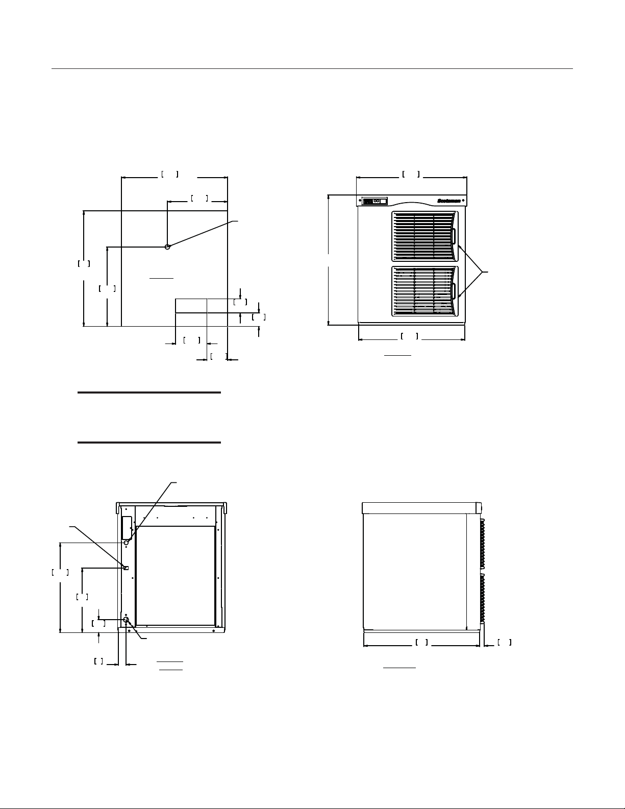
Page 5
NB0622, NB0922, FB1222, NB1322
24.00
REF.
61
22.00 REF.
55.9
2.92
7.4
6.48
16.5
2.81
7.1
4.30
10.9
16.50
41.9
12.50
31.8
ICE DROP
OPENING
PLAN VIEW
ULTRA SONIC
BIN LEVEL
SENSOR
OPTIONAL
12.40
31.5
2.68
6.8
1.59
4
14.65
37.2
2.17
5.5
AIR COOLED
BACK VIEW
3/4" FPT
DRAIN
.88 DIA.
ELECTRICAL
ACCESS
3/8" FLARE
MACHINE
WATER
INLET
22.00
55.9
23.00
[58.5]
22.89
58.1
FRONT VIEW
LOUVER AND
REMOVABLE FILTER
A/C UNITS ONLY
24.00
61
.92
[2.4]
LEFT SIDE VIEW
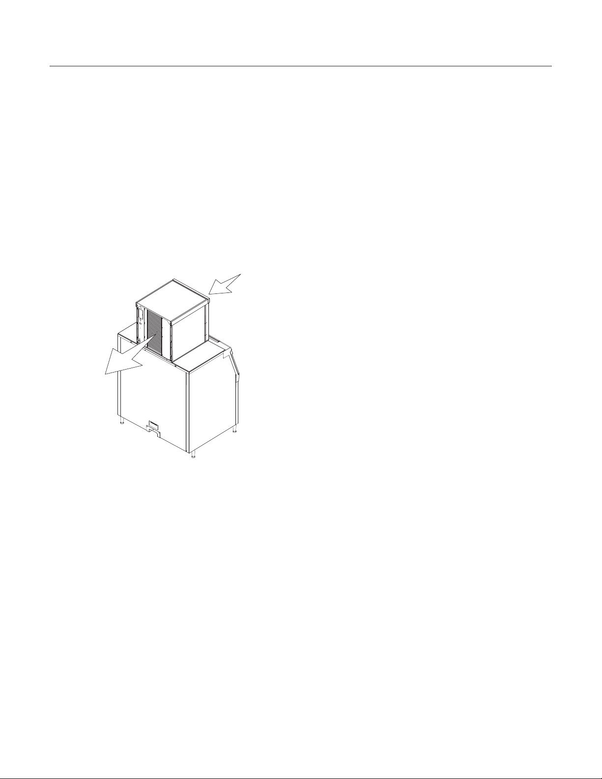
Installation and Use
NB0622 Cabinet Layout
Note: Bin Top Cut-outs for
drop zone should include
ultrasonic sensor location
[cm}
In
August 2011
Page 4
Page 6
NB0622, NB0922, FB1222, NB1322
24.00
REF.
61
22.00 REF.
55.9
2.92
7.4
6.48
16.5
2.81
7.1
4.30
10.9
16.50
41.9
12.50
31.8
ULTRA SONIC
BIN LEVEL
SENSOR
OPTIONAL
PLAN VIEW
ICE DROP
OPENING
13.39
34
2.67
6.8
18.64
47.3
1.59
4
AIR COOLED
BACK VIEW
3/8" FLARE
MACHINE
WATER
INLET
.88 DIA.
ELECTRICAL
ACCESS
3/4" FPT
DRAIN
27.00
[68.6]
22.00
55.9
22.89
58.1
FRONT VIEW
LOUVER AND
REMOVABLE FILTER
A/C UNITS ONLY
24.00
61
.92
2.3
LEFT SIDE VIEW
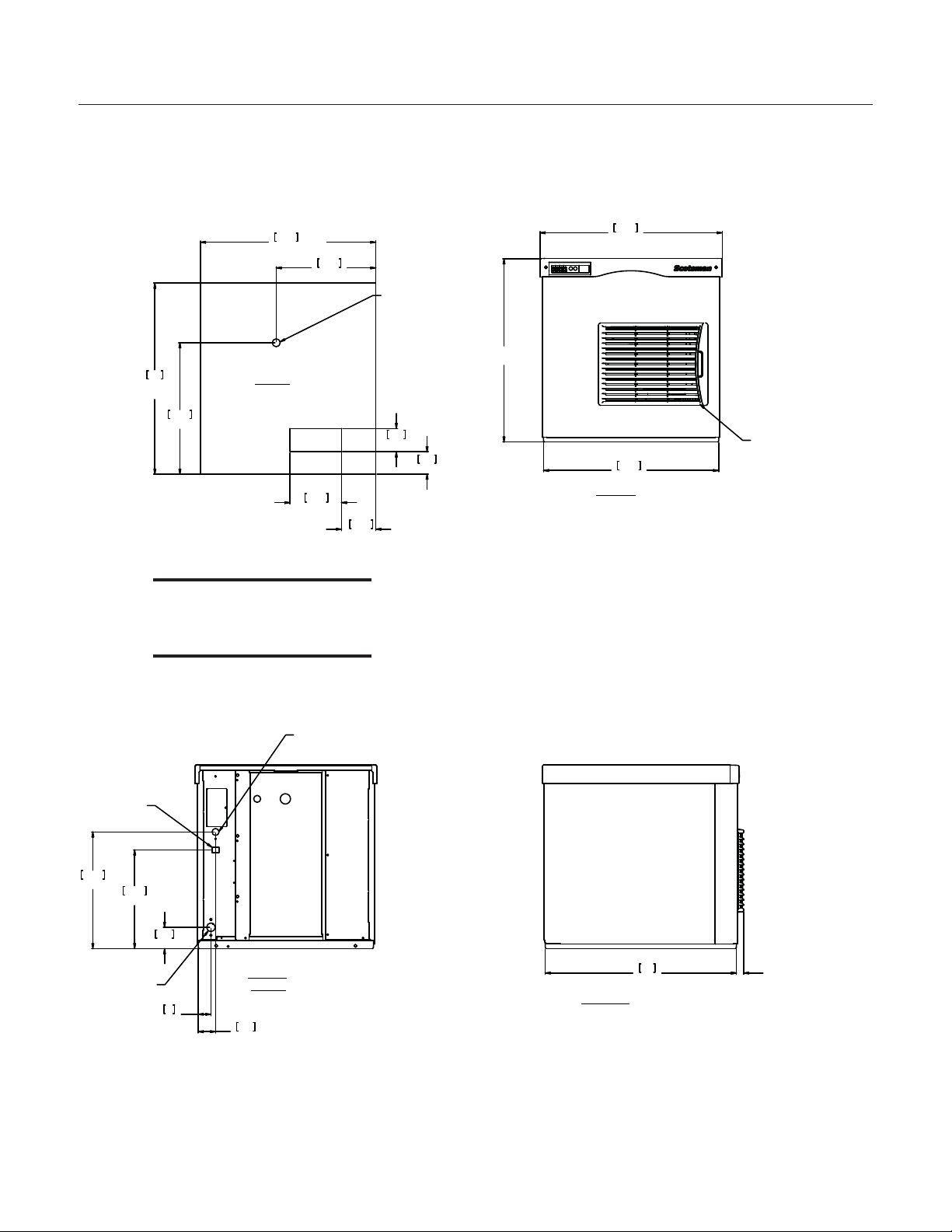
Installation and Use
NB0922, FB1222, NB1322 Cabinet Layout
Note: Bin Top Cut-outs for
drop zone should include
ultrasonic sensor location
[cm}
In
August 2011
Page 5
Page 7
NB0622, NB0922, FB1222, NB1322
Installation and Use
Unpacking & Install Prep
Remove the carton from the skid. Check for hidden
freight damage, notify the carrier immediately if any
is found. Retain the carton for the carrier’s
inspection.
The machine is not bolted to the skid. If strapped
remove the strap.
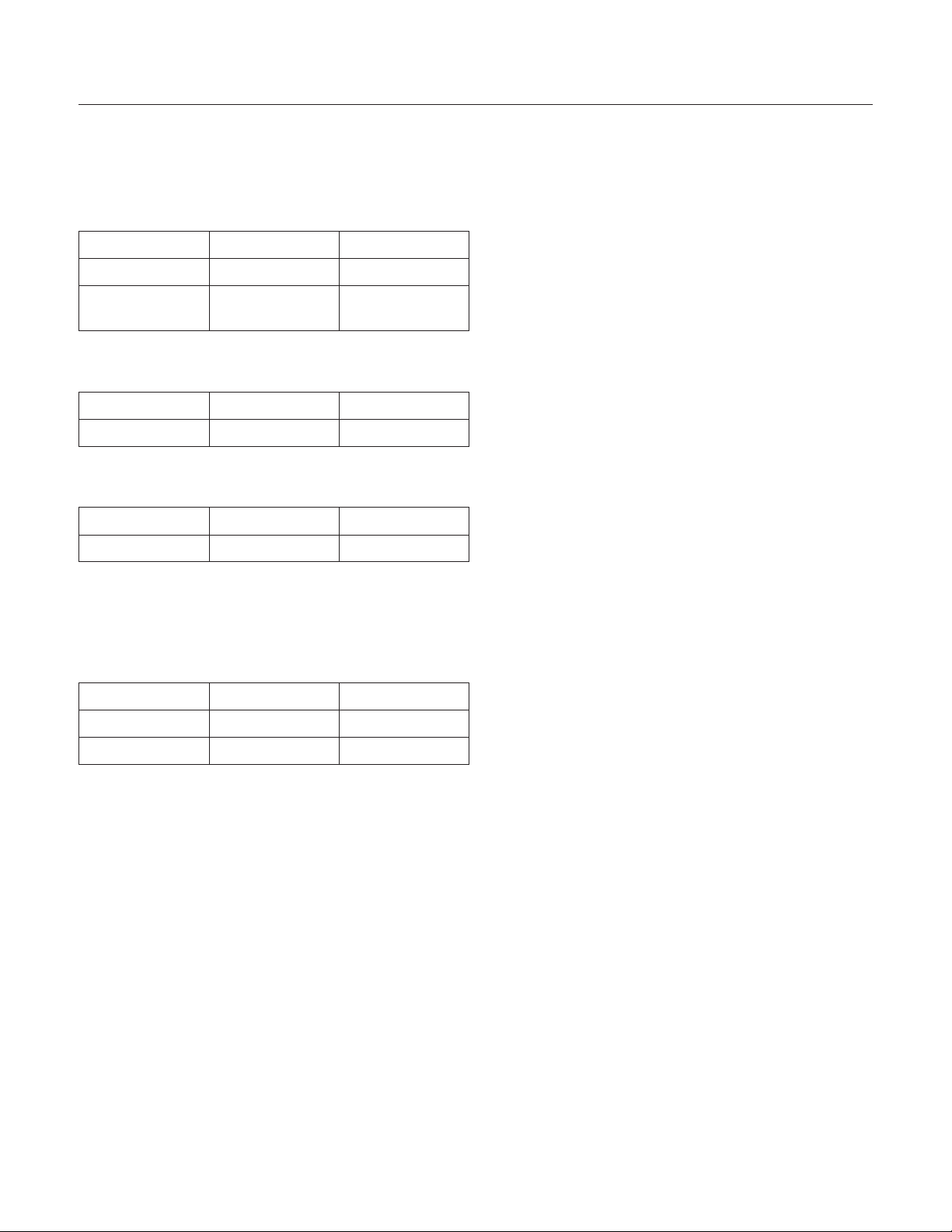
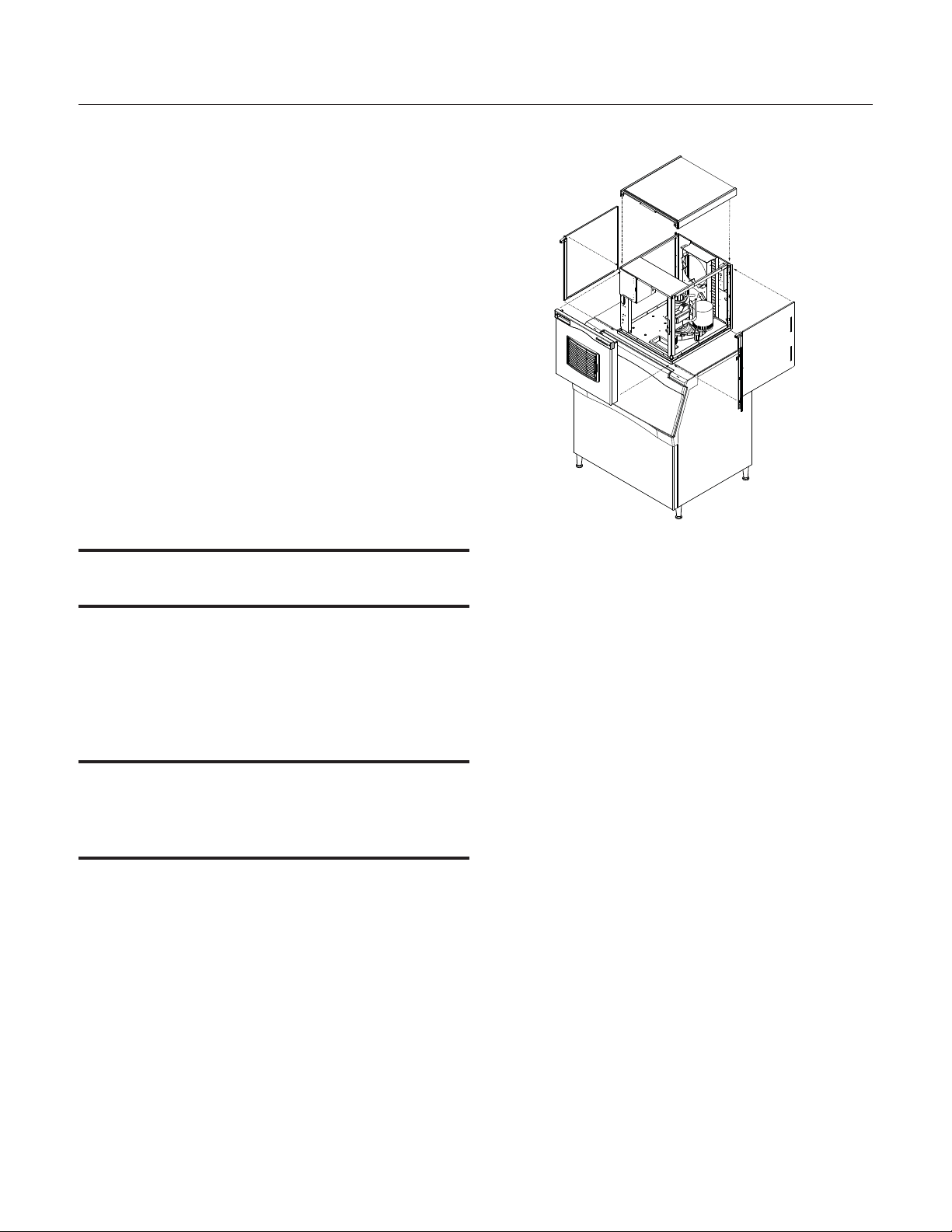
Place on Bin or Dispenser
If reusing an existing bin, be sure that the bin is in
good shape and that the gasket tape on the top is
not torn up. Water leaks, not covered by warranty,
could result from a poor sealing surface.
Install the correct adapter, following the directions
supplied with that adapter.
Hoist the machine onto the adapter.
Note: The machine is heavy! Use of a mechanical
lift is recommended.
Position the machine on the bin or adapter. Secure
with straps from the hardware bag packed with the
machine, or those supplied with the adapter.
Panel Removal
1. Locate and loosen the two screws at the front
edge of the top panel.
2. Pull the front panel out at the top until it clears
the top panel.
3. Lift the front panel up and off the machine.
Remove any plastic covering the stainless steel
panels.
Note: The standard machine set up includes visible
on and off switches. Those can be covered up by
changing the bezel in the front panel’s trim strip. A
cover-up bezel is included with the hardware bag.
Remove any packaging, such as tape or foam
blocks, that may be near the gear reducer or ice
chute.
Level the bin and ice machine front to back and left
to right by using the bin leg levelers.
4. Remove two screws at the front of the top panel.
Lift up the front of the top panel, push the top panel
back an inch, then lift to remove.
5. Locate and loosen the screw holding each side
panel to the base. Left side panel also has a screw
holding it to the control box.
6. Pull the side panel forward to release it from the
back panel.
Button Switch Bezel
To change bezels: Remove the front panel, and
refer to the instruction label on the inside of the
front panel. Push snaps of standard bezel in and
pull the bezel out of the front panel trim strip.
Locate other bezel. Push into the trim strip from the
front until it snaps into place. Return the front panel
to its original position and secure it to the cabinet
August 2011
Page 6
Page 8
NB0622, NB0922, FB1222, NB1322
Installation and Use
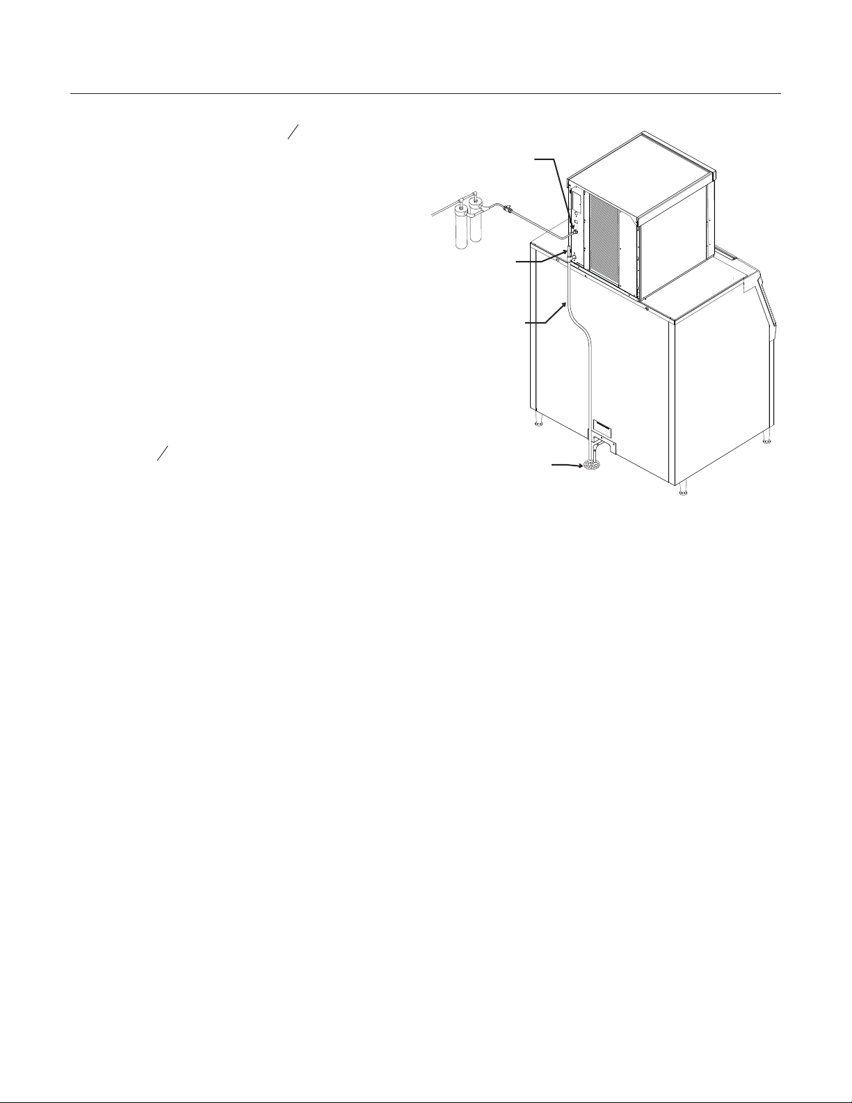
Water Supply and Drains
The water supply for ice making must be cold,
potable water. There is a single
potable water connection on the back panel.
Backflow
The design of the float valve and reservoir prevents
potable water backflow by means of a 1" air gap
between the reservoir's maximum water level
and the float valve water inlet orifice.
3
” male flare
8
Water Inlet
Drain Vent
Drain
There is one ¾” FPT condensate drain fitting at
the back of the cabinet.
Attach Tubing
Connect the potable water supply to the potable
water fitting,
3
” OD copper tubing or the equivalent
8
is recommended.
Water filtration is recommended. If there is an
existing filter, change the cartridge.
Drains - use rigid tubing: Connect the drain tube to
the condensate drain fitting. Vent the drain.
Do not Tee ice machine drains into the drain tube
from the ice storage bin or dispenser. Back ups
could contaminate and / or melt the ice in the bin or
dispenser. Be sure to vent the bin drain.
Follow all local and national codes for tubing, traps
and air gaps.
Condensate
Drain
Building Drain
Air Cooled Plumbing
August 2011
Page 7
Page 9
NB0622, NB0922, FB1222, NB1322
Ground
Wire
Connection
Black
White
Ground
Power
Supply
Wires
Install
Strain
Relief
Junction
Box
Cover
Installation and Use
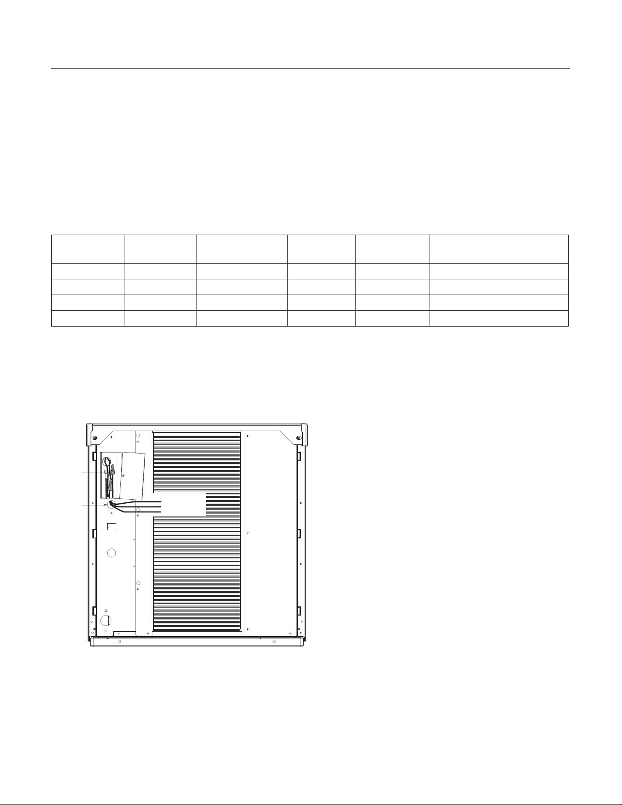
Electrical - All Models
The machine does not include a power cord, one
must be field supplied or the machine hard wired to
the electrical power supply.
Connect electrical power to wires inside the
junction box in the back of the cabinet. Use a strain
relief and connect a ground wire to the ground
screw.
The junction box for the power cord is on the back
panel. See detail below.
Remote models power the condenser fan motor
from marked leads in the junction box.
Refer to the dataplate on the machine for minimum
circuit ampacity and determine the proper wire size
for the application. The dataplate (on the back of
Do not use an extension cord. Follow all local and
national codes.
the cabinet) also includes the maximum fuse size.
Model
Dimensions
w"xd"xh"
NB0622A-1 same 115/60/1 Air 18.3 25
NB0922A-32 22 x 24 x 27 208-230/60/1 Air 12.5 15
FB1222A-32 same 208-230/60/1 Air 12.5 15
NB1322A-32 same 208-230/60/1 Air 19.1 30
Voltage
Volts/Hz/Phase
Condenser
Type
Min Circ
Ampacity
Max Fuse Size or HACR
Type Circuit Breaker
Reference: Electrical Detail
August 2011
Page 8
Page 10
NB0622, NB0922, FB1222, NB1322
Installation and Use
Final Check List
After connections:
1. Wash out the bin. If desired, the interior of the
bin could be sanitized.
2. Locate the ice scoop (if supplied) and have it
available for use when needed.
Final Check List:
1. Is the unit located indoors in a controlled
environment?
2. Is the unit located where it can receive adequate
cooling air?
3. Has the correct electrical power been supplied to
the machine?
4. Have all the water supply connections been
made?
5. Have all the drain connections been made?
6. Has the unit been leveled?
Control Operation
Use and Operation
Once started, the ice machine will automatically
make ice until the bin or dispenser is full of ice.
When ice level drops, the ice machine will resume
making ice.
Caution: Do not place anything on top of the ice
machine, including the ice scoop. Debris and
moisture from objects on top of the machine can
work their way into the cabinet and cause serious
damage. Damage caused by foreign material is not
covered by warranty.
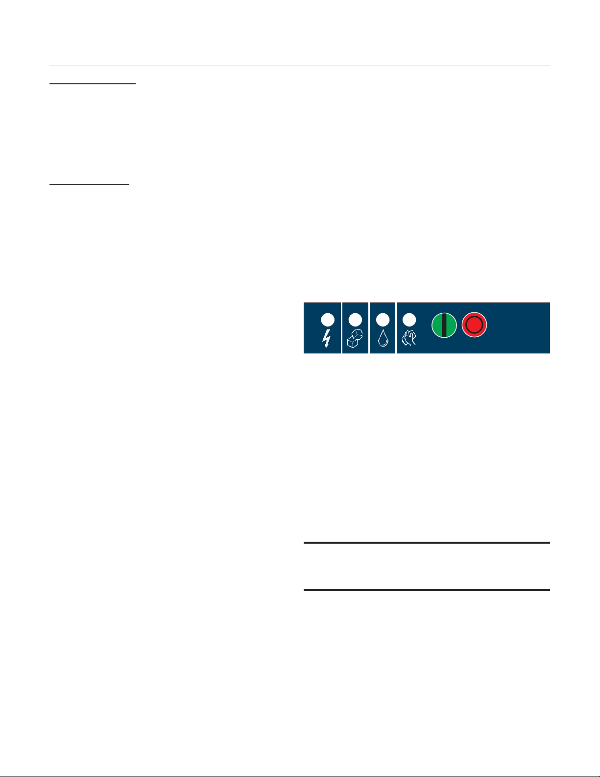
Power
Status
No
Water
Time to
Clean
On
Off
7. Have all unpacking materials and tape been
removed?
8. Has the protective covering on the exterior
panels been removed?
9. Is the correct bezel installed in the trim strip?
10. Is the water pressure adequate?
11. Have the drain connections been checked for
leaks?
12. Has the bin interior been wiped clean or
sanitized?
13. Have any water filter cartridges been replaced?
14. Have all required kits and adapters been
properly installed?
There are four indicator lights at the front of the
machine that provide information on the condition
of the machine.
Indicator Lights:
•
Power
•
Status
•
Water
•
De-scale & Sanitize
Note: If the De-Scale & Sanitize light is ON,
following the cleaning process will clear the light for
another cleaning time internal.
Two button switches are at the front – On and Off.
To switch the machine OFF, push and release the
Off button. The machine will shut off at the end of
the next cycle.
To switch the machine ON, push and release the
On button. The machine will go through a start up
process and then resume ice making.
August 2011
Page 9
Page 11

NB0622, NB0922, FB1222, NB1322
Installation and Use
Initial Start Up and Maintenance
1. Turn the water supply on.
2. Switch the electrical power on. Confirm voltage
is correct for the model.
3. Push and release the On button. The machine
will start in about two minutes.
4. Soon after starting, air cooled models will begin
to blow warm air out the back of the cabinet
After about 5 minutes, ice will begin to drop into
the bin or dispenser.
5. Check the machine for unusual rattles. Tighten
any loose screws, be sure no wires are rubbing
moving parts. Check for tubes that rub.
6. Fill out the warranty registration form and either
file it on line or mail it.
7. Notify the user of the maintenance
requirements and whom to call for service.
Maintenance
Top bearing check
time the scale is removed.
Maintenance:
1. Pull air filter(s) from panel.
2. Wash the dust and grease off the filter(s).
3. Return it(them) to their original position(s).
Do not operate the machine without the filter in
place except during cleaning.
Maintenance:
If the machine has been operated without a filter
the air cooled condenser fins will need to be
cleaned.
They are located under the fan blades. The
services of a refrigeration technician will be
required to clean the condenser.
: At least twice a year or every
Air filters
Air cooled condenser
This ice machine needs five types of maintenance:
•
Air cooled models need their air filters or
condenser coils cleaned regularly.
•
All models need scale removed from the
water system.
•
All models require regular sanitization.
•
All models require sensor cleaning.
•
All models require a top bearing check.
Maintenance Frequency:
Air filters
greasy air, monthly.
Scale removal
conditions it might be every 3 months. The yellow
De-Scale & Sanitize light will switch on after a set
period of time as a reminder. The default time
period is 6 months of power up time.
Sanitizing
often as needed to maintain a sanitary unit.
: At least twice a year, but in dusty or
. At least twice a year, in some water
: Every time the scale is removed or as
Maintenance:
The front and side panels are durable stainless
steel. Fingerprints, dust and grease will require
cleaning with a good quality stainless steel cleaner
Note: If using a sanitizer or a cleaner that contains
chlorine on the panels, after use be sure to wash
the panels with clean water to remove chlorine
residue.
Maintenance:
If the machine has been connected to water filters,
check the cartridges for the date they were
replaced or for the pressure on the gauge. Change
cartridges if they’ve been installed more than 6
months or if the pressure drops too much during
ice making.
Exterior Panels
Water filters
Sensor Cleaning
: Every time the scale is removed.
August 2011
Page 10
Page 12
NB0622, NB0922, FB1222, NB1322
Disconnect
From Sensor
Tubing
Installation and Use
Maintenance: Scale Removal and Sanitation
Note: Following this procedure will reset the
de-scale and sanitize light.
1. Remove front panel.
2. Push and release the Off button.
3. Remove ice from bin or dispenser.
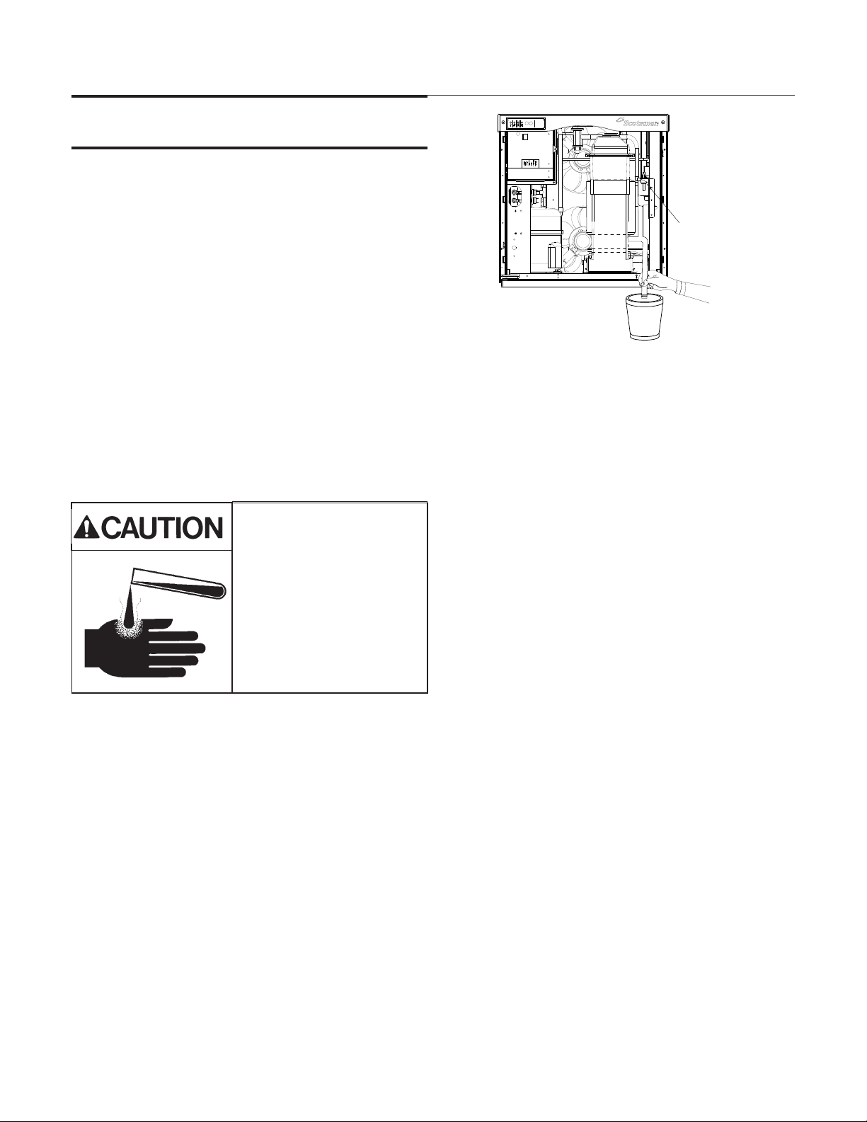
4. Turn the water supply to the float valve OFF.
5. Drain the water and evaporator by
disconnecting the leg of the hose connected to
the water sensor and draining it into the bin.
Return the hose to its original position.
6. Remove the water reservoir cover.
7. Mix a solution of 8 ounces of Scotsman Clear
One Scale Remover and 3 quarts of 95-115
degree F. potable water.
Ice machine scale remover
contains acids. Acids can
cause burns.
If concentrated cleaner
comes in contact with skin,
flush with water. If swallowed,
do NOT induce vomiting.
Give large amounts of water
or milk. Call Physician
immediately. Keep out of the
reach of children.
8. Pour the scale remover solution into the
reservoir. Use a small cup for pouring.
9. Push and release the Clean button: the auger
drive motor and light are on, C is displayed and
the De-scale light blinks. After 20 minutes the
compressor will start.
Drain Water
the water sensor and draining it into the bin or
a bucket. Return the hose to its original
position. Discard or melt all ice made during
the previous step.
13. To sanitize the water system, mix a locally
approved sanitizing solution. An example of a
sanitizing solution is mixing one ounce of liquid
household bleach and two gallons of 95 – 115
degree F. water.
14. Pour the sanitizing solution into the reservoir.
15. Push and release the On button.
16. Switch the water supply to the ice machine on.
17. Operate the machine for 20 minutes.
18. Push and release the Off button.
19. Wash the reservoir cover in the remaining
sanitizing solution.
20. Return the reservoir cover to its normal
position.
10. Operate the machine and pour the scale
remover into the reservoir until it is all gone.
Keep the reservoir full. When all the scale
remover solution has been used, turn the water
supply back on. After 20 minutes of ice making
the compressor and auger motor will shut off.
11. Turn the water supply to the ice machine OFF
12. Drain the water reservoir and evaporator by
disconnecting the leg of the hose connected to
June 2010
21. Melt or discard all ice made during the
sanitizing process.
22. Wash the inside of the ice storage bin with the
sanitizing solution.
23. Push and release the On button.
24. Return the front panel to its original position
and secure with the original screws.
Page 11
Page 13

NB0622, NB0922, FB1222, NB1322
Bail Clamp
Installation and Use
Maintenance: Check Top Bearing
This task should only be done by a qualified
service technician
The bearing in the breaker should be checked at
least two times per year.
Check the bearing by:
1. Removing the bail clamp and ice chute cover
Breaker
Cover
3. Removing the water shed & unscrewing the
breaker cover (left hand threads).
2. Unscrewing the ice sweep
Inspect the top of the bearing. When new the
grease is white, over time some gray will appear
over the rollers, that is normal. Add grease to
replace the gray grease or if gaps between rollers
are visible. If grease is watery, all gray or rust is
visible, have the bearing replaced. See the next
page for more information.
Note: When checking the top bearing, always
inspect the drip pan for water seal leaks. If water is
present in the drip pan, service the water seal and
check the gear reducer's lubricant. See the next
page.
August 2011
Page 12
Page 14

NB0622, NB0922, FB1222, NB1322
Installation and Use
Bearing Service
This task should only be done by a qualified
service technician
If the grease is uniformly white, no further action is
needed. If very gray, rusty, wet or has any
embedded metal, have the bearing replaced.
Grease
If the bearing only needs grease, or to confirm the
quality of the grease low in the bearing, inject
grease into the lower part of the bearing using
Scotsman grease needle pn 02-3559-01 and
Scotsman bearing grease cartridge, pn
A36808-001. Be sure to inject grease evenly and
thoroughly.
Bearing
Needle, pn
02-3559-01
Drip Pan
Check Drip Pan For Water
Change De-Scale Notification Interval
This feature is accessible only from standby
(Status Light Off).
1. Press and hold Clean button for 3 seconds.
This starts the Time to Clean Adjustment State
and displays the current time to clean setting.
2. Press the clean button repeatedly to cycle
through the 4 possible settings:
3. Push Off to confirm the selection.
August 2011
Page 13
•
1 year
•
0 (disabled)
•
4 months
•
6 months(default)
Page 15

NB0622, NB0922, FB1222, NB1322
Installation and Use
Maintenance: Sensors
The control that senses bin full and empty is a
photo-electric eye, therefore it must be kept clean
so it can “see”. At least twice a year, remove the
ice level sensors from the base of the ice chute,
and wipe the inside clean, as illustrated.
1. Remove front panel.
2. Pull photo eye holders forward to release them.
3. Wipe clean as needed. Do not scratch the
photo-eye portion.
4. Return the eye holders to their normal positions
and return the front panel to its original position.
Note: Eye holders must be mounted properly. They
snap into a centered position and are properly
located when the wires are routed to the back and
the left eye is the one with 2 wires at the connector.
The ice machine senses water by a probe located
near the water reservoir. At least twice a year, the
probe should be wiped clean of mineral build-up.
Probes
1. Shut off the water supply.
2. Remove front panel.
3. Remove the hose from the water sensor, use a
hose clamp pliers for this.
4. Loosen mounting screw and release the water
sensor from the frame of the unit.
5. Wipe probes clean,
August 2011
Page 14
Page 16

NB0622, NB0922, FB1222, NB1322
Installation and Use
What to do before calling for service
Normal Operation:
Ice
The machine will make either flaked or nugget ice,
depending upon the model. The ice will be
produced continuously until the bin is full. It is
normal for a few drops of water to occasionally fall
with the ice.
Heat
Air cooled models will generate heat, and it will be
discharged into the room.
Noise
The ice machine will make noise when it is in ice
making mode. The compressor and gear reducer
will produce sound. Air cooled models will add fan
noise. Some ice making noise could also occur.
These noises are all normal for this machine.
Reasons the machine might shut itself off:
•
Lack of water.
•
Does not make ice
•
Auger motor overload
•
High discharge pressure.
•
Low refrigeration system pressure.
Controller self test failure.
•
Check the following:
1. Has the water supply to the ice machine or
building been shut off? If yes, the ice machine will
automatically restart within minutes after water
begins to flow to it.
2. Has power been shut off to the ice machine? If
yes, the ice machine will automatically restart when
power is restored.
Machine Beeps:
If the machine has detected a condition requiring a
shut down, it will blink the Status Light and emit a a
beep once every second. To stop the beep, push
Off or reset the machine.
To Manually Reset the machine.
Push and release the Off button.
•
Push and release the On button.
•
To Shut the Machine Off:
Push and hold the Off button for 3 seconds or until
the machine stops.
Steady Green
Blinking Green
Blinking Red
Yellow
Blinking Yellow
Light Actions
Light Off
All Blinking
Indicator Lights & Their Meanings
Power Status Water
Normal Normal - -
Switching on or off.
Self Test
Failure
- Diagnostic shut down Lack of water -
-- -
- - - In Cleaning Mode
No power Switched to Off Normal Normal
When Smart-Board used,
machine attention
recommended.
Unit is remotely locked out - check with leasing company
--
De-Scale &
Sanitize
Time to descale
and sanitize
August 2011
Page 15
Page 17

NB0622, NB0922, FB1222, NB1322
On Off
Power
Status
De-scaleWater
Sanitize
AutoAlert Indicator Lights
Adjust Ice Level
Bin
Full
Max
Clean
Code
Display
Component Operation Indicator Lights
Code Description
.... ....Freeze Mode
flashes . . Freeze Mode is Pending
.... ....BinisFull
.... ....Clean Cycle
.... ....Board Locked
.... ....TestMode
.... ....Off
.... ....SelfTestFailed
flashes. . No ice sensed - Retrying
..... ....Noicesensed - Shut Down
flashes . Auger motor high load - Retrying
.... ....Auger motor high load - Shut Down
.... ....Nowater in reservoir
.... ....Refrigeration pressure too high / low
F
F
b
C
L
d
O
E
1
1
2
2
3
4
Technician Section
SEL
ENTER
ESC
Min
N
o
r
m
L
o
w
e
r
Control Operation - See Manual
Water Light On - Restore water supply
to machine.
De-scale Light On - Clean and sanitize
machine.
Test Mode - Depress Off for 3 seconds
then depress Clean for 3 seconds.
Recall Diagnostic Codes - Depress Off
for 3 seconds. Press Clean repeatedly
to go from most recent to oldest of 10.
Clear Diagnostic Codes - Switch unit off,
depress and hold Clean and Off for 3 seconds.
Reset from Code 1, 2, 3 or 4 - Depress Off
and then depress On.
02-4670-01
Information Display
Introduction to the Information Display
Removal of the front panel provides access to the
Information Display at the bottom of the control.
This section of the manual provides an explanation
of the use and capabilities of that display.
Information Display
Table of Contents
Use of Information Display and Buttons: ............................ Page 2
The Display includes Warnings and Data ............................ Page 3
Menu Tree ........................................... Page 4
Group Screens ......................................... Page 5
Advance Fault Definitions - Flaker or Nugget .......................... Page 6
Status List ............................................ Page 7
Cleaning ............................................. Page 8
Revision ............................................. Page 9
To Set the 7 Day Programmable Ice Level ........................... Page 12
Network Configuration ..................................... Page 14
Supplied Software ........................................ Page 15
Software Use: .......................................... Page 16
Chart Definitions ........................................ Page 17
Reference ............................................ Page 18
Access through Ethernet .................................... Page 19
Appendix ............................................ Page 20
August 2011
Page 1
Page 18

NB0622, NB0922, FB1222, NB1322
Information Display
Use of Information Display and Buttons:
Scroll Up
Button
Display Area
Scroll Up: Changes the display to a menu item
higher on the menu list or goes up one number on
a setting
Scroll Down: Changes the display to a menu item
lower on the menu list or goes down one number
on a setting
Select Button: Use to make changes to settings.
Enter Button: Changes display to a sub menu list.
Escape Button: Changes display to the main
menu.
Scroll Down
Button
Select
Button
Enter
Button
Communication Features:
The control can communicate information in three
ways:
•
Display: The two line display is controlled by
the buttons on the front.
•
USB: There is a USB connection on the front.
It can be used by a laptop or other PC type
computer to read, download or log data.
Scotsman software is required.
•
There is an Ethernet connection for use on a
network.
Other Features:
Connection
Escape Button
USB
7 Day Programmable Ice Level Control is available.
Instructions for programing are included in these
instructions.
August 2011
Page 2
Page 19

NB0622, NB0922, FB1222, NB1322
Information Display
Information types include Warnings and Data
Data available by scrolling through the menus:
Warning
•
Power Interrupts
•
Time to Clean
•
Button Lock
•
Time to Clean Interval
•
Time Since Last Cleaning
•
Compressor Runtime
•
Pwr Up Time
•
Warnings - will appear in display only after malfunction. Status light will blink green until warning
conditions clear.
Self-Test Failure
•
No Ice Pending
•
No Ice Strikeout
•
Auger High Load Pending
•
Auger High Load Strikeout
•
Menu Groups: Push and release the down arrow key to scroll
down to the next line in the display or group.
Date - preset
No Water
•
Refrigeration Pressure Too
•
High/Low
No Ice Warning
•
Auger Load Warning
•
Bin Level
•
Bin Level Setting
•
Freeze Timer (in 00:00 format)
•
Relay Voltage
•
Board Voltage
•
Auger Motor Current
•
Falling Ice Count
•
Bin Stat
•
Date: 12-20-2010
Time: 03:33:10PM
Time - preset to Central Time
Warnings
Base Faults
Adv (advanced) Faults
Status
Cleaning
Performance
Test Cubers only
Timers
Revision
Setup
PGM Bin Level
Warnings
Base Faults
Adv Faults
Status
Cleaning
Performance
Test
Timers
Revision
Setup
Setup
PGM Bin Level
PGM Bin Level
Network Config
Network Configuration
August 2011
Page 3
Page 20

NB0622, NB0922, FB1222, NB1322
Information Display
Menu Tree
Date and Time Preset
Warnings
Self-Test Failure
No Ice Pending
No Ice Strikeout
Auger High Load Pending
Auger High Load Strikeout
No Water
Refrigeration Pressure Too High/Low
No Ice Warning
Auger Load Warning
Base Faults
Fault code 1:
Fault code 2:
Fault code 3:
Fault code 4 :
Fault code 5 :
Fault code 6 :
Fault code 7 :
Fault code 8 :
Fault code 9 :
Fault code 10 :
Adv Faults descriptions of faults
Self-Test Failure
No Ice Pending
No Ice Strikeout
Auger High Load Pending
Auger High Load Strikeout
No Water
Refrigeration Pressure Too High/Low
Status
Warranty Start
Relay Voltage
Board Voltage
Auger Motor Current
Auger Motor Trip Current
Auger Motor Strikes
Ice Making Sensed
Ice Making Strikes
Freeze Timer
Ultrasonic Bin Level
Ultrasonic Bin Level Setpoint
Power Interrupt Counter
Bin Stat Input
Cleaning
Cleaning Interval (hrs of power time)
Next Cleaning Due
Last Cleaning Performed
Performance
% Runtime Calculation
Timers
Compressor Run Time
Compressor Run Time Resettable
Power Up Time
Power Up Time Resettable
Revision
Smart Board SW
Controller SW
KVS SW
Smart Board HW
Controller HW
Ethernet SW
Setup
Current Date
Current Time (12:00:00 am format)
Machine Model Number
Machine Serial Number
Machine Manufacturer
Equipment Name
Date of Manufacture
Contact Name
Contact Phone Number
Audible Alert
Clear current log file
Clear fault history
Logging Rate
Auger Current Warning Value
Ice Detect Warning Value
PGM Bin Level*
Bin Level Ctrl
Set Bin Level Ctrl On Off
Monday time 1
Monday level 1
Monday time 2
Monday level 2
Monday time 3
Monday level 3
Monday time 4
Monday level 4
Tuesday time 1
Tuesday level 1
Tuesday time 2
Tuesday level 2
Tuesday time 3
Tuesday level 3
Tuesday time 4
Tuesday level 4
Wednesday time 1
Wednesday level 1
Wednesday time 2
Wednesday level 2
Wednesday time 3
Wednesday level 3
Wednesday time 4
Wednesday level 4
Thursday time 1
Thursday level 1
Thursday time 2
Thursday level 2
Thursday time 3
Thursday level 3
Thursday time 4
Thursday level 4
Friday time 1
Friday level 1
Friday time 2
Friday level 2
Friday time 3
Friday level 3
Friday time 4
Friday level 4
Saturday time 1
Saturday level 1
Saturday time 2
Saturday level 2
Saturday time 3
Saturday level 3
Saturday time 4
Saturday level 4
Sunday time 1
Sunday level 1
Sunday time 2
Sunday level 2
Sunday time 3
Sunday level 3
Sunday time 4
Sunday level 4
Network Configuration
IP Address Read
Subnet Mask Read
Default Gateway
DNS Read
DHCP Enable
Update IP Address
Update Subnet Mask
Update Default Gateway
Update DNS
Update DHCP
Update Network On Next Power
Cycle
August 2011
Page 4
Page 21

NB0622, NB0922, FB1222, NB1322
Information Display
Group Screens
Within each group are several screens of either information or settings, like
times, that can be changed.
Date and Time Groups: No submenus are available.
Warnings: Press and release the Enter button to see information on current
Warnings.
Press and release ESC to return to the prior menu.
Base Faults: Press and release the Down arrow to underline the B in Base
Faults, then the Enter button to see in the display:
Most recent failure (labeled 0) and how long ago it occurred (in hours), then
press and release the down arrow to see:
Second to most recent failure (labeled 1) and how long ago it occurred (in
hours), then press and release the down arrow to see the third, fourth, fifth,
and so on up to ninth where the list ends.
If there are no errors, the screen will display End of Errors.
Note: Base Faults are cleared when the controller's are cleared.
Press and release the escape button to return to the main menu tree.
Press and release the down arrow key to underline the A in Advanced Faults.
Warnings
Base Faults
No Warnings
Warnings
B
ase Faults
End of Errors
Base Faults
A
dv Faults
Advanced Faults: Press and release the Enter button to see in the display:
Most recent failure and the exact time it occurred. Pressing and releasing the
down arrow cycles through the other failures back to the oldest.
If there are no Advanced Faults or at the end of the list the display shows fault
que end.
Note: Advanced Faults are not cleared by the controller, instead they are
cleared using the Clear Fault History screen in Setup.
At the end of the list the display will show directions to go back to the main
menu.
Press and release the escape button to return to the main menu tree.
fault que end
up arrow = back
esc = main menu
August 2011
Page 5
Page 22

NB0622, NB0922, FB1222, NB1322
Information Display
Advance Fault Definitions - Flaker or Nugget
Self-Test Failure
The controller checks for proper operation at power up. If the check shows a problem, this warning or
fault will be displayed.
No Ice Pending
The controller monitors ice making using the photo eyes. If falling ice is not sensed by the photo-eyes,
and if it is NOT the third consecutive time it has occurred, this warning or fault will be displayed.
No Ice Strikeout
If the controller fails to sense ice for a third consecutive time, this warning or fault will be displayed and
the machine will be shut down.
Auger High Load Pending
The controller monitors the current used by the auger drive motor. If the current exceeds the limit, and if
it is NOT the third consecutive time that it has, this warning or fault will be displayed.
Auger High Load Strikeout
If the auger motor draws too much current for a third consecutive time, this warning or fault will be
displayed and the unit will be shut down.
No Water
If the water level sensor is dry or the water is too pure, this warning or fault will be displayed, and the unit
will be shut off.
Refrigeration Pressure Too High/Low
There are two pressure switches on the machine, if either one opens due to an over or under pressure
condition, the controller will display this fault or warning.
August 2011
Page 6
Page 23

NB0622, NB0922, FB1222, NB1322
Information Display
Status List
Press and release the down arrow to underline the S in Status.
Press and release the Enter button to see:
Adv Faults
S
tatus
Warranty Start
: The display will show the warranty start date after 24 hours of
run time. Press and release the Down arrow to see:
Relay Voltage
: Voltage supplied to the relays. Press and release the Down
arrow key to see:
Board Voltage
: Voltage supplied to operate the controller. Press and release
the Down arrow key to see:
Auger Motor Current
: Current draw of the auger drive motor. Press and
release the Down arrow key to see:
Auger Motor Trip Current
: Maximum allowed amp draw. Press and release
the Down arrow key to see:
Auger Motor Strikes
: Number of times auger motor has currently exceeded
the amp draw setpoint. Press and release the Down arrow key to see:
Ice Making Sensed
: Has the controller sensed ice making? Press and release
the Down arrow key to see:
Ice Making Strikes
: Number of times the controller has not sensed ice falling
in the chute. Press and release the Down arrow key to see:
Freeze Timer
: Current compressor on time in minutes. Press and release the
Down arrow key to see:
KVS Level
: Distance in inches the ice level control system has measured from
the sensor to the top of the ice. Press and release the Down arrow key to see:
KVS Level Setpoint
: Distance in inches the ice level system will maintain as a
maximum ice level. Press and release the Down arrow key to see:
Warranty Start:
Starts at 24HRS
Relay Voltage:
240 VAC
Board Voltage:
14 VAC
Auger Mot Current
1.8 Amps AC
Aug Mot Trip Curr
3.0 Amps AC
Auger Mot Strikes
0
Ice Making Sensed
Yes
Ice Making Strikes
0
Freeze Timer:
00:00
KVS Level
00:00
KVS Level Setpoint
0
Power Interrupt Counter
: Number of times power has been interrupted to the
machine. Press and release the Down arrow key to see:
Bin Stat Input
: Shows Closed if no bin thermostat is attached or if one is
attached and is Closed. Shows open only if there is a bin thermostat attached
and it is open, which stops ice making. When done with Status, press and
release the ESC button.
August 2011
Page 7
Pwr Interrupts
0
Bin Stat
Opem
Page 24

NB0622, NB0922, FB1222, NB1322
Information Display
Cleaning
Push and release the Down arrow to put the line under the C in Cleaning.
Then push and release the Enter button to see.
The Clean Interval
The Next Clean Due in x HRS
. Then press and release the Down arrow to see:
. Then press and release the Down arrow to
see:
Last Clean: x HR Ago
.
Then press and release the Down arrow and then press and release the ESC
button.
Push and release the Down arrow to put the line under the P in Performance.
Performance: Push and release the Enter button to see:
Percent run time
. Then press and release the Down arrow to see:
When done with Performance, press and release the ESC button.
Push and release the Down arrow to put the line under the T in Timers. Then
press and release the Enter button to see:
Timers. Push and release the Enter button to see
Status:
C
leaning
Clean Interval:
6 Months
Next Clean Due
in 5 Months
Last Clean:
6 Hours Ago
Cleaning
P
erformance
Percent run time
0.00%
Performance
T
imers
Compressor run time
Compressor run resettable.
. Then press and release the Down arrow to see:
Press the Down arrow to go to the next line or
Optional Press SEL to enter reset mode.
Press Enter to reset compressor run time to 0. Suggested if compressor is
replaced.
Press the Down arrow to go to Power up time
. Then press and release the
Down arrow to see:
Power on resettable
. Press the Down arrow to go to the next line or Optional
Press SEL to enter reset mode.
Press Enter to reset Power on time to 0.
When done with Timers, press and release the ESC button.
Compressor Run:
HR
Comp Resettable:
0HR
Press enter to
clear counter
Pwr Up Time:
HR
Pwr Resettable:
HR
August 2011
Page 8
Page 25

NB0622, NB0922, FB1222, NB1322
Information Display
Revision
Push and release the Down arrow to put the line under the R in Revision.
Then push and release the Enter button to see:
Revision. SW Rev
number.
Then press and release the Down arrow to see:
Controller SW
(software rev number) Then press and release the Down arrow
to see:
US Bin Level software
revision. Then press and release the Down arrow to
see:
Hardware Rev
Then press and release the Down arrow to see:
Controller HW
(hardware rev number).
When done with Revisions, press and release the ESC button.
Push and release the Down arrow to put the line under the S in Setup.
Then push and release the Enter button to see:
Timers
R
evision
Smart-Board SW R
3
Controller SW
1
KVS SW
140
Smart-Board HW R
2
Controller HW
1
Revision
S
etup
Setup:
View the Date or change it.
To Set Day, Month and Year
Press SEL key to get to Setup screen
Push and release the SEL key to move to another underlined number.
Push and release the Up or Down arrow key to change the marked character.
Push and release the Select key to move to the next character, repeat prior
step to change the character.
When done, push and release the Enter key.
Then press and release the Down arrow to view the time or change it.:
To Set Time
Press SEL key to get to Setup screen
Push and release the SEL key to move the underline to another number.
Set Date:
Date: 12
Set Time:
Date: 02
-21-2010
:07:51PM
Push and release the Up or Down arrow key to change the marked character.
Push and release the Select key to move to the next character, repeat prior
step to change the character.
August 2011
Page 9
Page 26

NB0622, NB0922, FB1222, NB1322
Information Display
When done, push and release the Enter key.
Then press and release the Down arrow to view the
Model number
.
Model Number
Then press and release the Down arrow to view the
Serial number
Then press and release the Down arrow to view the
Manufacturer
Then press and release the Down arrow to view the
Equipment Name
Then press and release the Down arrow to view the
Manufacture date
Then press and release the Down arrow to view the
Contact name
Optional - change contact
Then press and release the Down arrow to view the
Contact phone number
. Optional - change contact phone number
Serial Number
Manufacturer
Scotsman Ice
Equipment Name
Ice Machine
Manufacture Date
Contact Name
Contact Phone Nu
Then press and release the Down arrow to view the
Audible Alert
.
Optional: Press SEL to switch the audible alert on or off. The default in this
model is ON.
Then press and release the Down arrow to view the. Then press and release
the Down arrow to view the screen to clear the current log file.
Optional: Press SEL to clear the log file.
Then press and release the Down arrow to view the Clear Fault History
file.
Then press and release the Down arrow to view the
Optional: Press SEL to clear the fault history.
Logging rate
. Then press and release the Down arrow to view the logging
rate. Default is data recorded every 30 seconds.
Note: Changing the logging rate is not recommended.
Audible Alert
On
Clear current
log file
Press Select to
clear log
Clear Fault
History
Press Select to
clear fault code
Logging Rate
30 Seconds
August 2011
Page 10
Page 27

NB0622, NB0922, FB1222, NB1322
Information Display
Auger Warning - Press and release the Down arrow to view the
Ice Detect Warning
- Press and release the Down arrow to view the
Any of the above can be modified by changing the settings as noted below.
The warning set points can be adjusted to match local conditions, so that
when they change the Smart-Board provides a notice of the change.
To Change Setup Settings:
From a specific Setup Menu Item, press SEL key to get to Setup screen. Push
and release the SEL key to move the underline to another number.
Push and release the Up or Down arrow key to change the marked character.
Push and release the Select key to move to the next character, repeat prior
step to change the character.
When done, push and release the Enter key.
Example 1: Change Contact Phone Number
Push the Down arrow key until Setup is visible and the S is underlined. Press
Enter.
Auger warning
setpoint
Ice Detect
warning setpoint
Revision
S
etup
Repeatedly push and release the Down key until the Contact Phone Number
appears. Press SEL key to get to the Setup screen
Push and release the SEL key to move the underline to the number you wish
to change. Push and release the Up or Down arrow key to change the marked
character.
Push and release the Select key to move to the next character, repeat prior
step to change the character.
When done, push and release the Enter key.
Set Contact Phon
1800SCOTSMAN
August 2011
Page 11
Page 28

NB0622, NB0922, FB1222, NB1322
Information Display
To Set the 7 Day Programmable Ice Level
There are four times and levels available for each day of the week.
Use Up or Down Arrow keys to scroll to PGM Bin Level screen. When the P
in PGM is underlined, press and release the Enter key.
Bin Level Ctrl is on the screen. If it reads Off, push and release the down
arrow button to begin programming.
Bin Level Ct
If Bin Level Ctrl is On, push and release the SEL
O
n
button. From On, push the Down arrow key to turn
Off. The control must be set to OFF to adjust bin
level. Push Enter and Down to get to the first
Set Bin Level Ct
O
ff
programming menu.
Monday Time 1 will show on the screen. Press and release the SEL key to
begin setting Monday Time 1. Set Monday Time appears in the display.
Change Monday Time 1:
12:00 AM might be displayed. To adjust, push the
SEL button to position the underline mark under the character to be changed.
Push and release the up or down arrow key to change the number or letter
one time. Repeat pushing the SEL button to move the underline and repeat
pressing the up and down arrow buttons to change the time.
Setup
P
GM Bin Level
Bin Level Ct
O
ff
Monday Time 1
01:30 AM
Set Monday Time
12:00 AM
Monday Time 1
02:30 AM
Push Enter once to change the screen back to Monday Time 1. Push Down
once to get to the level reading.
Change Monday Level 1:
Monday Level 1 is in the
display. Push SEL once to display Set Monday Level 1.
Rotate the knob one click at a time until the desired
level appears. A delay is normal
.
Note: smaller numbers = higher ice level.
Push Enter one time to set the level. "Off" means the switch is set for
maximum ice level.
Push the Down arrow to go to Monday Time 2, and set that time using SEL
and arrow buttons as in Change Monday Time 1 above. Push Enter once to
set it and change back to Monday Time 2. Push the down arrow button to go
to Monday Level 2 and change that level using the SEL button and the knob
as in Change Monday Level 1 above. Push Enter to set that level.
Repeat for all time and level settings.
When done, push ESC to return to the PGM Bin Level screen. When the P in
PGM is underlined, press and release Enter.
Bin Level Ctrl will show on the screen. Push and release the SEL button.
Push and release up arrow key to change the setting from Off to On.
Push and release Enter and ESC when done.
Monday Level 1
9 inches
Set Monday Level
14 inches
Monday Time 2
11:00 AM
Monday Level 2
9 inches
Set Monday Level
14 inches
Setup
P
GM Bin Level
Bin Level Ct
O
ff
Set Bin Level Ct
On
August 2011
Page 12
Page 29

NB0622, NB0922, FB1222, NB1322
Information Display
This table shows the default times and levels, which can be changed using the instructions on the
previous page.
Monday Tuesday Wednesday Thursday Friday Saturday Sunday
Time 1 12 AM 12 AM 12 AM 12 AM 12 AM 12 AM 12 AM
Level 1 9999999
Time 2 5 AM 5 AM 5 AM 5 AM 5 AM 5 AM 5 AM
Level 2 9999999
Time 3 12 PM 12 PM 12 PM 12 PM 12 PM 12 PM 12 PM
Level 3 9999999
Time 4 5 PM 5 PM 5 PM 5 PM 5 PM 5 PM 5 PM
Level 4 12 12 12 12 12 12 12
Example: Unit on a tall bin (44" or more). Adjusted to low ice levels during the week, high ice levels
during the weekend. Off = highest ice level.
Monday Tuesday Wednesday Thursday Friday Saturday Sunday
Time 1 1:00 AM 1:00 AM 1:00 AM 1:00 AM 1:00 AM 1:00 AM 1:00 AM
Level 1 32 32 32 32 32 Off Off
Time 2 11:00 AM 11:00 AM 11:00 AM 11:00 AM 11:00 AM 11:00 AM 11:00 AM
Level 2 32 32 32 32 32 Off 14
Time 3 3:00 PM 3:00 PM 3:00 PM 3:00 PM 3:00 PM 3:00 PM 3:00 PM
Level 3 32 32 32 32 32 Off 32
Time 4 7:00 PM 7:00 PM 7:00 PM 7:00 PM 7:00 PM 7:00 PM 7:00 PM
Level 4 32 32 32 32 Off Off 32
Note: Units on dispensers or short bins should not set their level other than 9 or Off - setting too low will
result in no ice.
Record your settings here for future reference:
Monday Tuesday Wednesday Thursday Friday Saturday Sunday
Time 1
Level 1
Time 2
Level 2
Time 3
Level 3
Time 4
Level 4
August 2011
Page 13
Page 30

NB0622, NB0922, FB1222, NB1322
Information Display
Network Configuration
Used only when connected to a network. There is an Ethernet connector on
the back of the Information Display board. If desired, route a network cable
thru the cabinet and connect your network to it.
To view or change the Network Configuration, use the up and down arrow
keys to display Network Configuration. When the N in Network is underlined,
press and release the Enter key.
The IP address (if connected to a network) will be displayed. If not connected,
Please Wait will be displayed for an extended time.
Press the down arrow key to see the Subnet Mask
Press the down arrow key to see the Default Gateway
Press the down arrow key to see the DNS
PGM Bin Level
N
etwork Configu
IP Address
Subnet Mask
Default Gateway
DNS
Press the down arrow key to see DHCP Enable
Press the down arrow key to see the Update IP Address screen. Press the
SEL key to access it.
Press the up or down arrow key to change the first (underlined) number.
Press the SEL key to move the underline to the next number, then press the
up or down key to change that number. Repeat as needed to change the
numbers. When done, press the Enter key.
Repeat the same process to change the other network parameters, if needed.
Once desired network parameters have been manually configured, turn on
“Update Network on Next Power Cycle”. After the power to the machine has
been cycled, the new parameters will take affect.
DHCP Enable
Update IP Address
Set Update IP Ad
August 2011
Page 14
Page 31

NB0622, NB0922, FB1222, NB1322
Information Display
Supplied Software
Description:
Scotsman Prodigy Tech Tool is a software program designed to access the Prodigy ice machine's
Information Display control. It can read and display the data in the controller. The data is converted to
chart form and can then be saved and / or printed. It is on the CD-ROM and must be installed onto the
PC that will be used to connect through the USB port. Use is optional.
Installation and Use
Requirements:
Windows XP or Vista or Windows 7
•
40 MB disk space minimum. More will be needed if data logging is used.
•
Desktop or Laptop PC with a USB port.
•
Live ice machine (to install USB driver)
•
Software Installation:
Pre-installation: USB cable UNPLUGGED from the the PC.
1. Insert the CD into the computer’s CD-ROM drive.
2. Follow the program installation instructions. At the finish, do NOT start the application.
•
The installation will place 2 icons on the desktop, Prodigy Charting and Scotsman Prodigy.
•
The installation will also set up a Scotsman Prodigy section under Programs (Start > All Programs
> Scotsman Prodigy).
3. After the installation is complete, remove the CD-ROM
from the drive.
4. Power up the unit and plug the USB connector into the
PC and the USB port.
5. The PC will automatically find and begin the process to
install the driver.
6. Select all default settings for installing the device driver.
7. Installation is now complete.
August 2011
Page 15
Page 32

NB0622, NB0922, FB1222, NB1322
Information Display
Software Use:
With the unit powered and connected to the computer's USB port, Open
Scotsman Prodigy:
Start, All Programs, Scotsman Prodigy, Prodigy
Click on Get File. The software will automatically begin to download the
information. Once that is complete either click on Chart Data or select a
new log file to review. If selecting a log file for this
machine, be sure Nugget is checked.
When you click on Chart Data, the Column Selection
dialog box will appear. You can select any chart you want
to review. The default is all of them. Click on OK to go to
the next step.
The software will display the Charting information box.
You may have to expand it to see the Chart Type
selection area on the right.
Use the Chart
available charts.
Which one of these to use depends upon
what the machine situation is. For example, if
the machine is down, displaying code 2,
indicating an auger motor over amp condition,
it would be useful to check auger motor
current. Checking the Base Faults
Advanced Faults
understand what occurred and when.
Another example is a complaint of low
capacity. The chart on Power up time
show if the machine is on all the time. Then a
look at the freeze timer
often it is cycling. The two will provide a good idea of the machine's ability to
produce ice.
At any time clicking on the Render PDF button will generate all the charts in
PDF format so they can be saved. Once saved they can be printed or
emailed.
Type box to display the list of
or
is another way to
should
chart will show how
August 2011
Page 16
Page 33

NB0622, NB0922, FB1222, NB1322
Information Display
Chart Definitions
Op Mode = The mode the controller was in at the time shown
•
Error Code = The codes, if any, of any diagnostic codes.
•
Warning = The codes, if any, of any warnings. Same codes as diagnostic
•
Pwr Interrupts = Number of electrical power interruptions to the machine
•
Time to Clean=0=no,1=yes
•
Button Lock=0=no,1=yes
•
Time to Clean Interval = Time set between Cleaning light activations, in hours.
•
Compressor Run = Time compressor has been operating
•
Pwr Up Time = Time power connected to machine.
•
Bin Level = Ice level measured by the ice level control
•
Bin Setpoint = Set point of the ice level control
•
Freeze Timer = time in seconds that the compressor operated before bin full
•
Board Voltage = approximation of AC voltage to the control board from the transformer
•
Relay Voltage = AC load voltage determined by controller. 115 or 230.
•
Auger Motor Current = amp draw of the auger motor x10
•
Ice Making Sensed=0=notsensed, 1 = sensed
•
Bin Stat = Bin thermostat, when used. 0 open, 1 closed.
•
RLO = SmartLock option. 0 not locked, 1 locked
•
Ice Dispensed - not used
•
Water Dispensed - not used
•
Compressor = 0 off, 1 on
•
• Auger = auger motor. 0 off, 1 on
•
Bin Eyes Blocked = 0=no, 1=yes
August 2011
Page 17
Page 34

NB0622, NB0922, FB1222, NB1322
Information Display
Reference
Error Code Display
Example of generated PDF file
Op Mode Display
August 2011
Page 18
Page 35

NB0622, NB0922, FB1222, NB1322
Information Display
Access through Ethernet
1. After installation, connection to a network, and power up, scroll down to
locate IP Address.
2. Enter that IP address into an internet browser like Internet Explorer
or Firefox.
3. A Prodigy logo screen will appear. After a few seconds it will update
and show a screen similar to the one here. Login as an observer or
administrator using the password.
4. As an Observer, several actions are available at this screen:
Controller Snapshot
•
AFB Config File
•
Key Pad Lock Status
•
Time To Clean Setting
•
Controller Snapshot
controller.
AFB Configuration File
information display and the controller.
Key Pad Lock Status
Time to clean setting.
unit must accumulate before the De-Scale / Sanitize light is switched on.
Flush Level Setting
Bin Level Scheduling
control installed. Lists the times and levels that have been set.
Logging in as an Administrator allows additional actions:
lists the current status of many aspects of the
lists the current status of many aspects of the
lists if the key pad of the controller is locked or not.
Lists the number of months of power up time the
lists the Purge level the controller is set to use.
. Only applies to units that have the ice level
Flush Level Setting
•
Bin Level Scheduling
•
Change Password
•
Key Pad Lock or Unlock
changed by selection and submitting.
Adjust the Clean Notice
time the unit must accumulate before the De-Scale / Sanitize light is
switched on. Selecting a different interval and submitting will
change that number.
Adjust the Purge or Flush level
amount of water purged per cycle.
Start or stop the machine
stopped remotely.
. Lists if the controller is locked or not and can be
. Lists the number of months of power up
. Lists and allows change of the
. Allows the machine to be started or
August 2011
Page 19
Page 36

NB0622, NB0922, FB1222, NB1322
Information Display
Appendix
NAFEM Protocol. See the NAFEM website, www.nafem.org, for more
information.
August 2011
Page 20
Page 37

SCOTSMAN ICE SYSTEMS
775 Corporate Woods Parkway
Vernon Hills, IL 60061
800-726-8762
www.scotsman-ice.com
17-3368-01
 Loading...