

Page 1

N0622L, F0822L, N0922L, F1222L, N1322L, F1522L
Service Parts
This is the illustrated service parts list for the
Voltage codes:
N0622, F0822, N0922, F1222, N1322 and F1522
remote low side ice machine heads.
-1 = 115/60/1
Several models are listed together, be sure to
select the correct part based on the complete
model number, including voltage.
Table of Contents
Cabinet ...................................................Page 2
Refrigeration ................................................Page 3
Water and Chute ..............................................Page 4
N0622L, N0922L, N1322L Evaporator System ..............................Page 5
F0822L, F1222L, F1522L Evaporator System ...............................Page 6
Gear Reducer and Motor ..........................................Page 7
Electrical Control and Harnesses .....................................Page 8
Wiring Diagram ...............................................Page 9
Schematic Diagram ............................................Page 10
September 2009
Page 1
Page 2
N0622L, F0822L, N0922L, F1222L, N1322L, F1522L
Service Parts
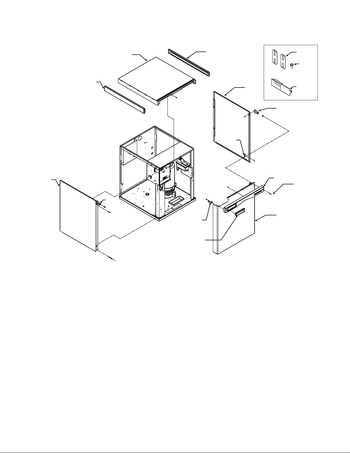
Cabinet
1
1a
3
2a
1b
2
2a
5
4a
4
4d
6
7
8
4b
4c
Item Part
Number Number Description
1 A39524-021 Top panel, incl 1a, 1b
1a 02-4221-01 Left trim strip
1b 02-4221-02 Right trim strip
2 A39445-022 Right side panel, incl 2a and 5
2a 02-4215-01 Screw receptacle
3 A39444-024 Left side panel, incl 2a and 5
4 A39443-024 Front panel, complete. Includes 4a, 4b, 4c, 4d
4a 02-4214-01 Trim strip
4b 03-1735-03 Screw
4c 02-4284-01 Bezel
4d 02-4216-01 Gusset
5 A39571-001 Clip
6 A30911-015 Machine straps
7 03-1405-15 Cap screw
8 02-4284-02 Bezel, partial window
September 2009
Page 2
Page 3
N0622L, F0822L, N0922L, F1222L, N1322L, F1522L
Service Parts
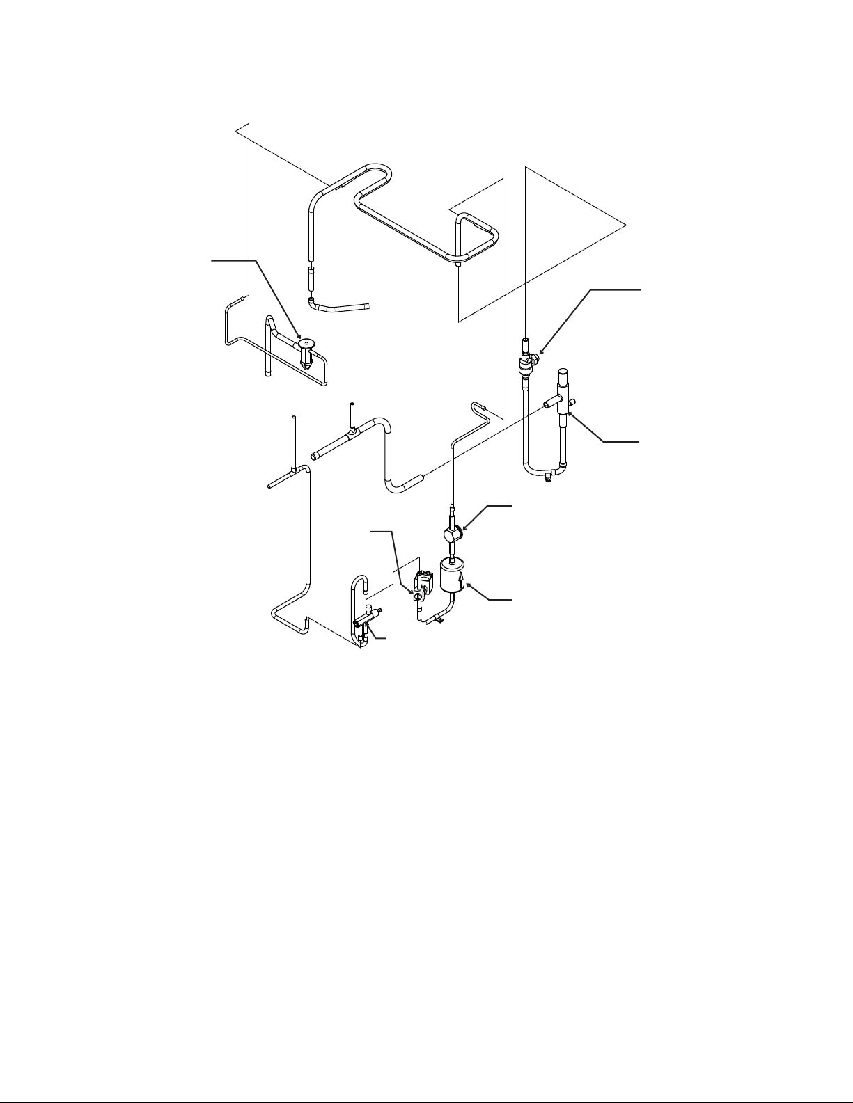
Refrigeration
7
1
5
Item Part
Number Number Description
1 11-0548-02 Ball valve
2 16-1143-01 EPR valve
3 16-0762-01 Sight glass
4 02-3319-02 Dryer
5 11-0493-02 Liquid line valve, 115 volt
6 16-1030-01 Liquid access valve
7 16-1144-22 TXV, N0622, F0822
16-1144-24 TXV, N0922, F1222
16-1144-23 TXV, N1322, F1522
02-4406-01 Insulation, TXV
2
3
4
6
September 2009
Page 3
Page 4

N0622L, F0822L, N0922L, F1222L, N1322L, F1522L
Service Parts
Water and Chute
1
22
2
21
19
20
29
26
27
28
18
25, 25a
16
15
14
24
26
23
17
13
12
3
4
5
6
11
7
8
9
10
10
Item Part
Number Number Description
1 A39199-001 Right top channel
2 02-4449-21 Water sensor
3 A34969-001 Bail clamp
4 02-2930-04 Chute cover
5 03-1405-52 Cap screw
6 02-3001-01 Ice sweep
7 02-3841-01 Ice chute
8 13-0929-01 Insul collar, flaker
13-0929-02 Insul collar, nuggets
9 02-2929-04 Ice chute, lower
10 A37708-021 Bin control set
11 A39200-001 Reservoir bracket
12 02-4338-01 Evaporator inlet hose
13 02-3371-01 Water reservoir & valve
02-3371-02 Float and arm only
02-3266-03 Plunger/seat only
14 02-4339-01 Drain hose
15 16-1039-01 Connector, male
16 16-0835-01 Flare fitting, male
17 A39182-001 Post, right front
18 A39184-001 Post, control box
19 A39197-001 Back panel
20 03-1394-01 Pal nut
21 A39185-001 Left top panel
22 A39181-001 Control box cover
23 03-3804-01 Receptacle
24 A38732-001 Panel mount
25 13-0895-01 Tubing, order 3
25a 16-0871-01 Insert (for valve end)
26 03-1531-01 Screw
27 A39025-001 Bracket
28 02-3692-21 Drain fitting
29 02-4524-21 Base assembly
September 2009
Page 4
Page 5

N0622L, F0822L, N0922L, F1222L, N1322L, F1522L
Service Parts
N0622L, N0922L, N1322L Evaporator System
1
11
2
3
4
5
6
7
8
9
10
15
14
16
17
12
13
Item Part
Number Number Description
1 03-1405-52 Cap screw
2 02-3001-01 Ice sweep
3 13-0871-01 Water shed
4 02-2978-01 Lip seal
5 02-3128-20 Cover, includes item 4
6 13-0617-54 O-ring
7 08-0660-01 Auger stud
8 A34559-020 Bearing
9 02-2977-01 Lip seal
10 13-0617-52 O-ring - to chute
11 03-1544-08 Screw, socket head
15
18
19
20
21
12 A32900-020 Nugget breaker
assembly, includes items 3,4,5,6,8,9 and 13
13 13-0617-45 O-ring
14 A38071-021 Auger, N0622
A38071-022 Auger, N0922, N1322
15 02-0929-23 Water seal
16 02-4350-21 Evaporator, N0622
02-4352-21 Evaporator, N0922, N1322
17 02-4352-01 Collar
18 A32777-001 Retaining ring
19 13-0868-01 Water shed
20 02-3837-01 Drip pan
21 13-0704-00 Gasket
September 2009
Page 5
Page 6

N0622L, F0822L, N0922L, F1222L, N1322L, F1522L
Service Parts
F0822L, F1222L, F1522L Evaporator System
1
14
3
5
10
12
2
4
6
7
8
9
11
13
18
18
17
19
20
15
16
Item Part
Number Number Description
1 03-1405-52 Cap screw
2 02-3001-01 Ice sweep
3 13-0871-01 Water shed
4 02-2978-01 Lip seal
5 02-3128-20 Cover, includes item 4
6 13-0617-54 O-ring
7 08-0660-01 Auger stud
8 A34559-020 Bearing
9 02-2977-01 Lip seal
10 16-0617-52 O-ring, to chute
11 03-1403-27 Screw
12 02-2916-01 Slotted collar
13 13-0617-49 O-ring, under slotted collar
21
22
23
24
14 03-1544-08 Screw, socket head
15 A34505-020 Flaker breaker assembly,
includes items 3,4,5,6,8,9, and 16
16 03-0617-45 O-ring
17 A38071-021 Auger, F0822
A38071-022 Auger, F1222, F1522
18 02-0929-23 Water seal
19 02-4350-21 Evaporator, F0822
02-4352-21 Evaporator, F1222, F1522
20 02-4358-01 Collar
21 A32777-001 Retaining ring
22 13-0868-01 Water shed
23 02-3837-01 Drip pan
24 13-0704-00 Gasket
September 2009
Page 6
Page 7

12
N0622L, F0822L, N0922L, F1222L, N1322L, F1522L
Service Parts
Gear Reducer and Motor
1
14
2
4
5
6
7
8
ITEM PART
9
10
11
NUMBER NUMBER DESCRIPTION
1 12-2430-21+ Drive motor, 115 volt
2 12-2430-44 Start switch
3 12-2430-29 Bearing
4 13-0868-01 Water Shed
5 A32379-029* Seal
6 A32379-022 Gearcase Cover*
7 A32379-026 Bolt
8 A32379-024 First Gear & Bearings
9 A32379-023 2nd Gear & Bearings
10 A32379-021 Gasket
11 A32379-020 Gear Case
12 A33220-030 Gearcase kit, assembled
w/out motor, includes item 13
13 A32379-027 Oil, 1 Container
14 A33220-021** Complete 115 volt
3
13
* Cover includes output shaft, seal, gear and bearings.
If water has flowed thru the seal, the gearcase cover
assembly should be replaced, not just the seal.
** Includes items 1, 12, and is charged with gear oil.
+ Includes items 2 and 3.
September 2009
Page 7
Page 8

N0622L, F0822L, N0922L, F1222L, N1322L, F1522L
Service Parts
Electrical Control and Harnesses
4
5
Item Part
Number Number Description
1 12-2780-01 Terminal block
2 A39198-001 Control box side cover
3 12-2924-01 Transformer, 115 volt
4 A39216-001 Shield
5 11-0575-22 Controller
02-4407-01 Graphic overlay
02-4076-01 Control box cover
1
2
3
Not Shown
12-2977-01 High voltage harness
12-2976-01 Low voltage harness
12-1638-19 Power cord
September 2009
Page 8
Page 9

CONTROL BOX
BK
W
O
V
TRANSFORMER
LINE
LOAD
3
2
1
GN
W
CONDUCTIVITY
PROBE
BK
R
BK
BK
R
GN
V
789
456
123
41256
3
BK
JUMPER
T1T2
BU
Y
LIQ LINE SOLONOID
R
START
RUN
OL
AUGER DRIVE
MOTOR
2
S-A1
BK
L2 L1
TERMINAL
BLOCK
1
4
BU
BU
BIN FULL
DETECTOR
(PHOTO TRANS)
Y
17-3215-01
CIRCUIT BOARD
USE COPPER CONDUCTORS ONLY
THIS UNIT MUST BE GROUNDED
SEE NAMEPLATE FOR
SUPPLY VOLTAGE
AND MAX. FUSE SIZE
EARTH GROUND
NC
CENTRIFUGAL
SWITCH
BIN FULL
EMITTER
(LED)
GN/Y
INLET
POWER
CORD
N0622L, F0822L, N0922L, F1222L, N1322L, F1522L
Service Parts
Wiring Diagram
September 2009
Page 9
Page 10

N0622L, F0822L, N0922L, F1222L, N1322L, F1522L
POWER SUPPLY
L1
L2
AUGER DRIVE
MOTOR
4
1
2
LIQUID LINE
SOL
N.O.
AUGER DRIVE
RELAY
COM
PRINTED
CIRCUIT
ASSEMBLY
N.O.
COMP DRIVE
RELAY
COM
CONDUCTIVITY PROBE
PHOTOTRANSISTOR
IR
LED
ALL CONTROLS SHOWN IN
ICE MAKING MODE
LINE
12V
TRANSFORMER
Service Parts
Schematic Diagram
September 2009
Page 10
 Loading...