

Scotsman MXG Series, MXG 438 A/W, MXG 638 A/W, MXG 938 A/W, MXG 328 A/W Technical Service Training
...Page 1

TECHNICAL SERVICE TRAINING
Welcome to another Scotsman technical service presentation
This one will cover the electronic MXG series Ice Cube Machines
MXG SERIES
CUBERS
MXG SERIES
Page 2

MXG 328 A/W
Max. Ice Production = 150 Kg/24h*
* 10/10°C= Air & Water Inlet Temperature
NEW MXG SERIES
Page 3

MXG 428 A/W
Max. Ice Production = 195 Kg/24h*
* 10/10°C= Air & Water Inlet Temperature
NEW MXG SERIES
Page 4

MXG 438 A/W
Max. Ice Production = 195 Kg/24h
*10/10°C = Air & Water Inlet Temperature
NEW MXG SERIES
Page 5

MXG 638 A/W
Max. Ice Production = 340 Kg/24h
*10/10°C = Air & Water Inlet Temperature
NEW MXG SERIES
Page 6

MXG 938 A/W
Max. Ice Production = 400 Kg/24h
*10/10°C = Air & Water Inlet Temperature
NEW MXG SERIES
Page 7

TOPICS
On the next slides are shown the following steps by steps
procedures:
• UNPACKING
• INSTALLATION
• START UP AND OPERATIONAL CHECKS
• OPERATING PRINCIPLES and COMPONENTS
• MAINTENANCE
• SERVICE ANALYSIS
NEW MXG SERIES
Page 8

UNPACKING
NEW MXG SERIES
Page 9

The machines are supplied
in a carton box secured by
two plastic strips to a
wooden base. Check first
the outside conditions of
carton box and wooden base
then cut the two plastic
strips, remove the tape and
then the carton box.
UNPACKING
NEW MXG SERIES
Page 10

Slip away – remove
plastic strip
UNPACKING
NEW MXG SERIES
Page 11

Remove front panel
air filter (AC version
only)
UNPACKING
NEW MXG SERIES
Page 12

Remove front panel
screws and the
panel
UNPACKING
NEW MXG SERIES
Page 13
Remove top panel
screws and the
panel
UNPACKING
NEW MXG SERIES
Page 14

Remove I/R bracket
installation
instruction and
water inlet and
outlet hoses
UNPACKING
NEW MXG SERIES
Page 15

Remove side
panels screws and
the panels
UNPACKING
NEW MXG SERIES
Page 16

UNPACKING
NEW MXG SERIES
…..unscrew
the unit
frame from
the wooden
base….
Page 17

The Modular Cuber machines
require for the installation the
use of a companion storage
bin to store the ice produced.
Perfect “matching” storage
been are:
SB 193 – 322 for MXG 328-428
SB 393 – 530 for MXG 438-638-938
UNPACKING
NEW MXG SERIES
Page 18

Due to design reason MXG
series can not be stacked:
• Ice chutes not aligned
• Not enough space for
Service over the bottom unit
top evaporator
• Not possible to remove
bottom unit front panel
UNPACKING
NEW MXG SERIES
Page 19

INSTALLATION
NEW MXG SERIES
Page 20

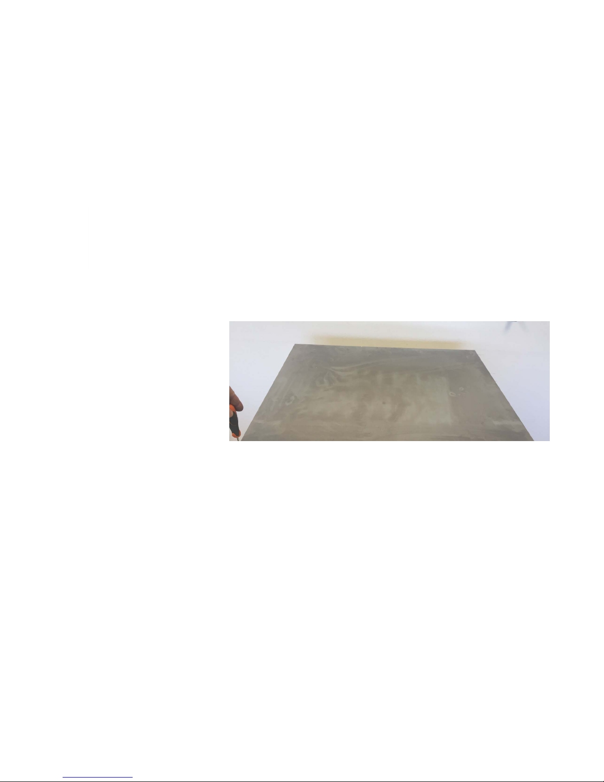
After having installed the
ice maker on top of chosen
bin, remove polystyrene
block form ice chute top
and remove the ice chute.
locate I/R and its bracket,
release the same from
clamps
INSTALLATION
NEW MXG SERIES
Page 21
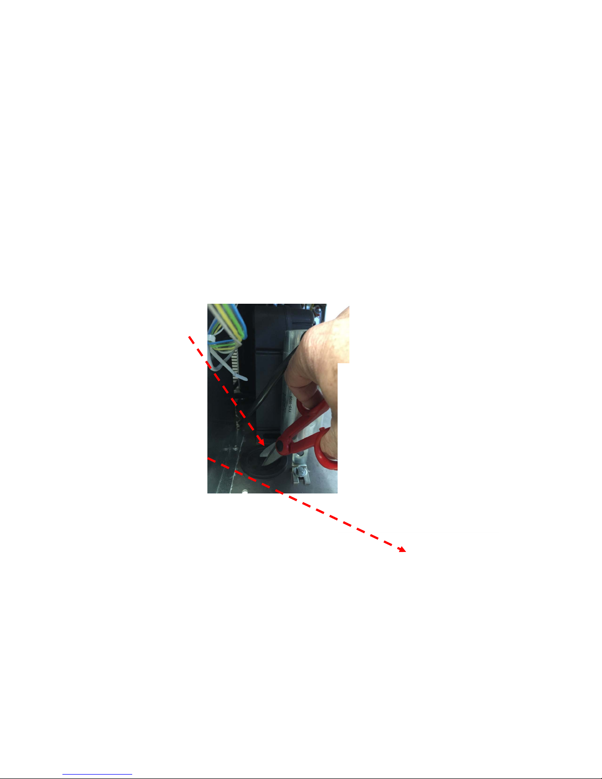
Cut the unit base
gasket , pass the
I/R sensor through
the same reaching
the inner bin area.
INSTALLATION
NEW MXG SERIES
Page 22

Fix the IR
by
supplied
screws to
related
bracket
INSTALLATION
NEW MXG SERIES
Page 23

Fix IR bracket at
ice chute
discharge area by
stainless steel
screw
INSTALLATION
NEW MXG SERIES
Page 24
Once installed optical level
sensor, re-install ice chute
previously removed paying
attention to hang the same
to its hook rim point.
INSTALLATION
NEW MXG SERIES
Page 25
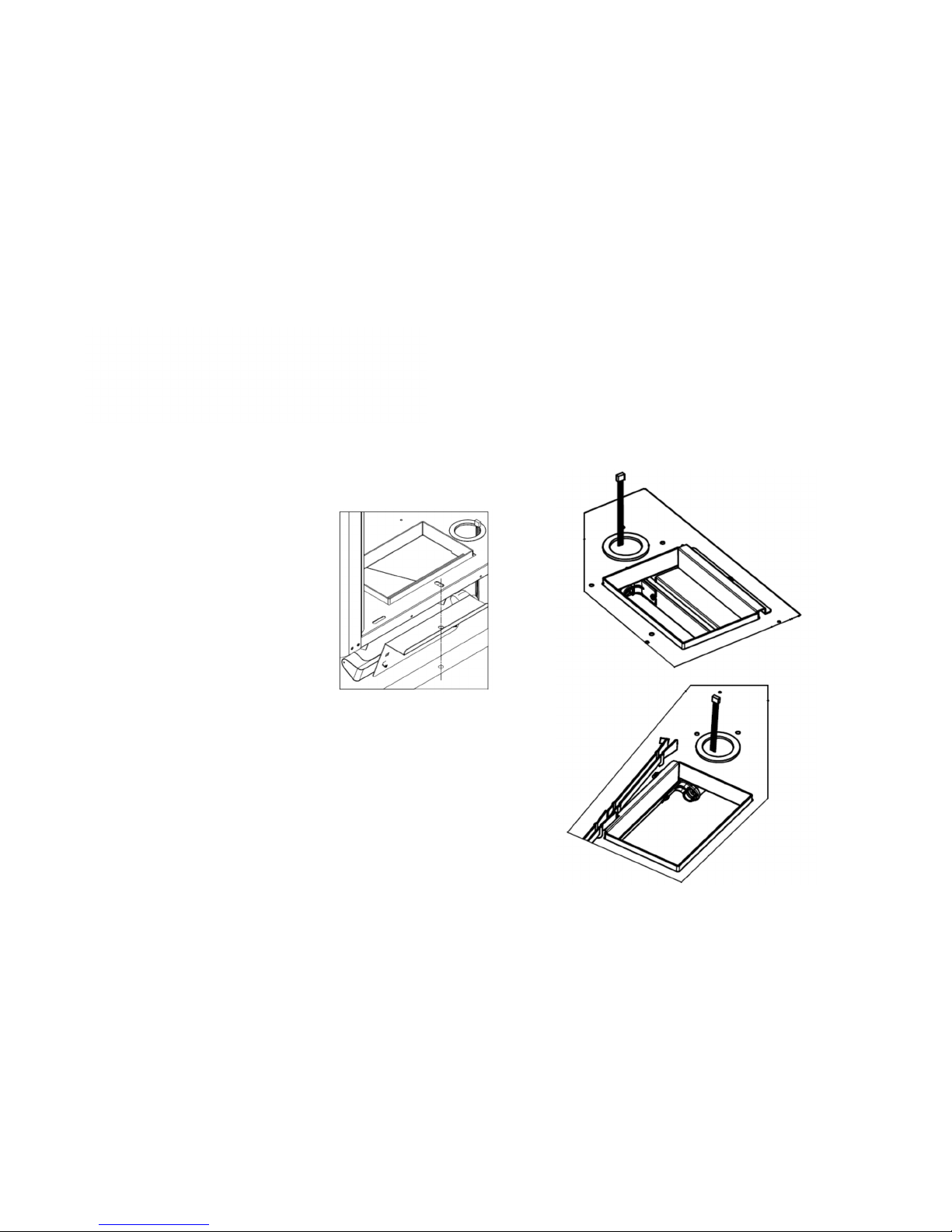
Note different
location
according to
MXG models
INSTALLATION
NEW MXG SERIES
MXG 328-428-438-938
MXG 638
Page 26

Check the data plate
of the machine
located on the rear
panel for correct
voltage as well as
for the proper
wiring/fuse size.
Remember that all
machines require a
solid earth wire.
INSTALLATION
NEW MXG SERIES
Page 27

Check for the correct water and ambient conditions that
should be:
• Min. ambient temperature 10ºC (50F)
• Max. ambient temperature 40ºC (100F)
• Min. water temperature 5ºC (40F)
• Max. water temperature 35ºC (90F)
• Min. water pressure 1 bar (14 PSI)
• Max. water pressure 5 bar (70 PSI)
INSTALLATION
NEW MXG SERIES
Page 28

Adequate space must
be left for proper water
and electrical
connections on the rear
side of the machine. A
minimum clearance of
15 cm on both sides for
best routing air.
INSTALLATION
NEW MXG SERIES
Min. space 15 cm
Page 29
NEW MXG SERIES
Air
filter
Air
filter
INSTALLATION
328 – 428 - 438 air flow
Page 30
NEW MXG SERIES
Air
filter
INSTALLATION
638 air flow
Air
filter
Page 31

NEW MXG SERIES
Air
filter
Air
filter
INSTALLATION
938 air flow
Page 32

Level the unit on
both directions front
to rear and right to
left side using the
adjustable legs.
STACKING INSTALLATION
NEW MXG SERIES
Page 33

Install, on the cable
supply with the
machine, an
adequate electrical
plug according to
the local standards
and regulations.
Maximum voltage
variation should be
±10%.
Machine must be
individually fuse
protected.
INSTALLATION - ELECTRICAL
NEW MXG SERIES
Page 34

Connect the water inlet 3/4” male
threat of the water inlet solenoid valve
to the water supply line by means of
the rubber hose provided with
machine.Install on water supply line
closed to the machine a water valve
(tap).
Connect the 20 mm O.D. fitting of the
water drain with the flexible hose
supply with the machine securing it by
proper
INSTALLATION – WATER PIPING
NEW MXG SERIES
Page 35

AIR COOLED VERSION
TYPICAL INSTALLATION
NEW MXG SERIES
POWER
WATER INLET
WATER DRAIN
HAND DISCONNECT
SWITCH
WATER
FILTER
WATER
VALVE
WATER DRAIN
Page 36

On the water
cooled version
there are two
separate 3/4”
male thread
water inlet
fittings…..
INSTALLATION
NEW MXG SERIES
Page 37

…..a second separate
drain hose must be
connected to the outlet
3/4” male fitting located
on the upper side of the
water regulating valve.
INSTALLATION
NEW MXG SERIES
Page 38

WATER COOLED VERSION
TYPICAL INSTALLATION
NEW MXG SERIES
POWER
WATER INLET
WATER DRAIN
HAND DISCONNECT
SWITCH
WATER
FILTER
WATER
VALVE
WATER DRAIN
Page 39

START UP AND
OPERATIONAL
CHECKS
NEW MXG SERIES
Page 40

Open the water tap/valve and Switch ON the power on the
electrical supply line.
START UP AND OPERATIONAL CHECKS
NEW MXG SERIES
Page 41

Green Lighted
Master Push
Switch located in
the front panel.
By pushing it is
possible to Switch
ON and OFF the
machine.
NEW MXG SERIES
START UP AND OPERATIONAL CHECKS
Page 42

Push the Green
Push Button
Switch to Start
Up the machine
START UP AND OPERATIONAL CHECKS
NEW MXG SERIES
Page 43

A start-up delay is
factory set at 60’ on the
models MXG 638 - 938
with the Yellow LED
blinking.
This delay can be set
up with the Jumper n.3
Jump IN = 0’
Jump OUT = 60’
FREEZING CYCLE
BIN FULL
POWER
TOO HI EVAP TEMP
TOO HI COND TEMP
PUSH
START UP AND OPERATIONAL CHECKS
NEW MXG SERIES
Page 44

START UP AND OPERATIONAL CHECKS
NEW MXG SERIES
Once the start delay is elapsed the Ice Machine will start up automatically
through the 5 minutes of “Water Filling Phase”.
Page 45

The components energized
during this period are:
• PC Board
START UP AND OPERATIONAL CHECKS
NEW MXG SERIES
Page 46

• Water Inlet Solenoid Valve
START UP AND OPERATIONAL CHECKS
NEW MXG SERIES
Page 47

• W ater drain
valve
START UP AND OPERATIONAL CHECKS
NEW MXG SERIES
Page 48

• Hot Gas
Solenoid
Valve
START UP AND OPERATIONAL CHECKS
NEW MXG SERIES
Page 49

During the first 5’ the water
goes through the Water Inlet
Valve then…
….flows into the small
orifice of the “Flow Control”
located on the outlet port of
the same.
START UP AND OPERATIONAL CHECKS
NEW MXG SERIES
Page 50

Following the plastic inlet
hose the incoming water
arrive on the upper side of
the evaporator….
.... where it flows onto the
plastic evaporator platen
dribbling down through the
holes located on the corners.
START UP AND OPERATIONAL CHECKS
NEW MXG SERIES
Page 51

Dribbled water is
collected down into
the water sump
where is located
the overflow that
assures the proper
water level and
quantity for the next
freezing cycle.
START UP AND OPERATIONAL CHECKS
NEW MXG SERIES
Page 52

START UP AND OPERATIONAL CHECKS
NEW MXGSERIES
Once the start delay is elapsed the Ice Machine will start up automatically
through the 5 minutes of “Water Filling Phase”.
Page 53

After the first 5’ of water filling
phase the machine start up
automatically on freezing cycle
with the following electrical
components in operation:
• Compressor
START UP AND OPERATIONAL CHECKS
NEW MXG SERIES
Page 54

• Water Pump
START UP AND OPERATIONAL CHECKS
NEW MXG SERIES
Page 55

• Fan Motor (on air cooled
version only)
START UP AND OPERATIONAL CHECKS
NEW MXG SERIES
Page 56

• Contactor
START UP AND OPERATIONAL CHECKS
NEW MXG SERIES
Page 57

The operation of the
fan motor is controlled
by a condenser
temperature sensor
located within the fins
of condenser that
transmit a signal to
the PC Board to
activate in ON-OFF
mode the fan motor
so to keep between
two pre-set values the
condenser
temperature and
pressure.
START UP AND OPERATIONAL CHECKS
NEW MXG SERIES
Page 58

On PC Board the LED energized are:
• Power
FREEZING CYCLE
BIN FULL
POWER
TOO HI EVAP TEMP
TOO HI COND TEMP
PUSH
START UP AND OPERATIONAL CHECKS
NEW MXG SERIES
Page 59

On PC Board the LED energized are:
• Power
• Freezing
FREEZING CYCLE
BIN FULL
POWER
TOO HI EVAP TEMP
TOO HI COND TEMP
PUSH
START UP AND OPERATIONAL CHECKS
NEW MXG SERIES
Page 60

Water is
circulating by
the water pump
into the
inverted tin
plated copper
molds of the
evaporator….
START UP AND OPERATIONAL CHECKS
NEW MXG SERIES
Page 61

….while the
refrigerant is
flowing into the
serpentine
welded on the
upper side of
the tin plated
copper molds.
START UP AND OPERATIONAL CHECKS
NEW MXG SERIES
Page 62

• EVAPORATOR
SENSOR
NEW MXG SERIES
Page 63

After
approximately 5
minutes since the
start up of the
freezing cycle, the
temperature of
the evaporator
serpentine drops
down to 0ºC….
START UP AND OPERATIONAL CHECKS
NEW MXG SERIES
0ºC
Page 64

….with the blinking of the small RED LED located in the center
of PC Board.
START UP AND OPERATIONAL CHECKS
NEW MXG SERIES
Page 65

After
approximately 10
minutes from the
start up of the
freezing cycle, the
temperature of
the evaporator
serpentine drops
down to - 15ºC….
START UP AND OPERATIONAL CHECKS
NEW MXG SERIES
-15ºC
Page 66

….with the light ON steady of the small RED LED located in the
center of PC Board.
START UP AND OPERATIONAL CHECKS
NEW MXG SERIES
Page 67

The machine
remains in the
freezing cycle till its
completion for an
additional time
according to the
set up of the first
four DIP SWITCH
of the PC Board.
START UP AND OPERATIONAL CHECKS
NEW MXG SERIES
Page 68

START UP AND OPERATIONAL CHECKS
NEW MXG SERIES
Page 69

Once completed the freezing
cycle the machine enters into
the defrost or harvest cycle
with the following electrical
components in operation:
• Compressor
START UP AND OPERATIONAL CHECKS
NEW MXG SERIES
Page 70

• Water Inlet Solenoid valve
START UP AND OPERATIONAL CHECKS
NEW MXG SERIES
Page 71

• Water Drain
Solenoid Valve
START UP AND OPERATIONAL CHECKS
NEW MXG SERIES
Page 72

• Hot Gas Valve
START UP AND OPERATIONAL CHECKS
NEW MXG SERIES
Page 73

The length of the defrost or
harvest cycle is controlled
by the PC Board according
to the setting of the DIP
SWITCH 5 and 6 and it is
related to the time that the
machine takes to drop the
evaporating temperature
from 0ºC to -15ºC (time T2)
as shown on the table.
A
SWITCH 5 AND 6
D
BC
START UP AND OPERATIONAL CHECKS
NEW MXG SERIES
LENGTH OF HARVEST CYCLE ACCORDING TO THE TIME TO DROP THE
EVAP. TEMPERATURE FROM 0ºC TO -13ºC
LENGTH PROGRAMS
HARVEST
CYCLE A B C D
180” Up to 6’ *** Up to 9’ ***
165” 6’-7’ Up to 3’ 9’-10’ ***
150” 7’-8’ 3’-3’15’ 10’-11’ ***
135” 8’-9’ 3’15”-3’30” 11’-12’ ***
120” 9’-10’ 3’30”-4’30” 12’-13’ Up to 3’
105” 10’-12’ 430”-6’ 13’-15’ 3-4’
90” >12’ >6’ >15’ >4’
Page 74

It’s possible to extend the length of the defrost cycle by
means of the DIP SWITCH 7 and 8 as per below chart.
ADDITIONAL DEF ROST TIME
78
ON ON 0
OFF ON 30"
ON OFF 60"
OFF OFF 90"
D I P SWITCH
START UP AND OPERATIONAL CHECKS
WATER PUMP OFF
NEW MXG SERIES
Page 75

During the defrost or
harvest cycle the
combined action of
refrigerant in Hot Gas
state and incoming
Water are going to
partially melt the ice
cubes in contact with
the tin plated copper
molts with the
dropping down of the
same through the
curtain.
START UP AND OPERATIONAL CHECKS
NEW MXG SERIES
Page 76

Ice maker turns OFF just when
bin is full by ice and cubes cut
the I/R beam.
It is possible to test I/R
operation by keeping some ice
cubes between lenses during
a defrost ……...
START UP AND OPERATIONAL CHECKS
NEW MXG SERIES
Page 77

The Bin Full YELLOW LED starts to blink slow.
FREEZING CYCLE
BIN FULL
POWER
TOO HI EVAP TEMP
TOO HI COND TEMP
PUSH
START UP AND OPERATIONAL CHECKS
NEW MXG SERIES
Page 78

..till defrost cycle is elapsed thus to release all ice cubes from
inverted mold cups; after that the machine will stop at bin full
condition with the yellow LED steady ON
FREEZING CYCLE
BIN FULL
POWER
TOO HI EVAP TEMP
TOO HI COND TEMP
PUSH
START UP AND OPERATIONAL CHECKS
NEW MXG SERIES
Page 79

As soon as the ice is removed between transmitter and received
the infrared beam is resumed immediately with fast a blinking of
the Yellow LED, then the machine restart with 45” of recharging
water
FREEZING CYCLE
BIN FULL
POWER
TOO HI EVAP TEMP
TOO HI COND TEMP
PUSH
START UP AND OPERATIONAL CHECKS
NEW MXG SERIES
Page 80

OPERATING
PRINCIPLES
and
COMPONENTS
NEW MXG SERIES
Page 81

Compressor
Evaporator
Air cooled
condenser
Hot
gas
valve
OPERATING PRINCIPLES - FREEZE
NEW MXG SERIES
Page 82

Compressor
Evaporator
Air cooled
condenser
Hot
gas
valve
OPERATING PRINCIPLES - HARVEST
NEW MXG SERIES
Page 83

OPERATING PRINCIPLES 938
NEW MXG SERIES
Liquid valves
Liquid valves
hot gas valves
Page 84

TXV
valves
factory
setting,
full
opening
(countercl
ockwise
then 1 turn
clockwise
OPERATING PRINCIPLES 938
NEW MXG SERIES
Page 85

OPERATING PRINCIPLES 938
NEW MXG SERIES
Evaporator
sensor location
Page 86

OPERATING PRINCIPLES 938
NEW MXG SERIES
Condenser
sensor
location
air cooled
version
Page 87

OPERATING PRINCIPLES 938 - FREEZE
NEW MXG SERIES
Condenser
sensor
location
water
cooled
version
SWEP
water
cooled
condenser
Page 88

OPERATING PRINCIPLES 938
NEW MXG SERIES
DANFOS
S water
regulating
valve set
at 17 bar
Page 89

WATER SYSTEM – FREEZING CYCLE
NEW MXG SERIES
Page 90

WATER SYSTEM – HARVEST CYCLE
FIRST PORTION 30”
NEW MXG SERIES
Page 91

WATER SYSTEM – HARVEST CYCLE
SECOND PORTION
NEW MXG SERIES
Page 92

OPERATING PRINCIPLES – PC BOARD
NEW MXG SERIES
Page 93

SWITCH 9
OPERATING TIME
OF WATER PUMP
DURING HARVEST
OFF = 15”
ON = 30”
SWITCH 7 AND 8
EXTENTION TIME OF
HARVEST CYCLE BY 0”, 30”,
60” OR WATER PUMP OFF
SWITCH 5 AND 6
LENGTH OF THE
HARVEST CYCLE
ACCORDING TO THE
TIME T
2
SWITCH 1, 2, 3 AND 4
SETTING OF THE
TIMED PORTION OF
FREEZING CYCLE
SWITCH 10
CONDENSER
SAFETY CUT OUT
TEMPERATURE
(60ºC WATER -
OFFAND 70ºC AIR
- ON)
OPERATING PRINCIPLES – DIP SWITCHES
NEW MXG SERIES
Page 94

OPERATING PRINCIPLES – JUMPERS
NEW MXG SERIES
Page 95

Time T
1
From start
up of
freezing
cycle till
the blinking
of 0°C Red
LED
OPERATING PRINCIPLES – PC BOARD
NEW MXG SERIES
Page 96

Time T
2
From
blinking of
Red LED
till the light
ON steady
of -15°C
Red LED
OPERATING PRINCIPLES – PC BOARD
NEW MXG SERIES
Page 97

Time T
a
Added time controlled
by the PC Board
according to the setting
of the DIP SWITCH
1, 2, 3 and 4.
LENGTH OF TIMED PORTION OF FREEZING
CYCLE – FIRST 4 SWITCHES
25’
13’
19’
11’
17’
3’
9’
15’
21’23’
7’ 5’
OPERATING PRINCIPLES – PC BOARD
NEW MXG SERIES
Page 98

Time T
s
Harvest Time TSis
controlled by the PC
Board and it is inversely
proportional to the Time
T2of the Freeze Cycle
(from 0ºC to -13ºC) as
per the combination A
of the Table.
Time TSis NOT
adjustable.
LENGTH OF HARVEST CYCLE ACCORDING TO THE TIME
TO DROP THE EVAP. TEMPERATURE FROM 0ºC TO -13ºC
LENGTH PROGRAMS
HARVEST
CYCLE A B C D
180” Up to 6’ *** Up to9’ ***
165” 6’-7’ Upto 3’ 9’-10’ ***
150” 7’-8’ 3’-3’15’ 10’-11’ ***
135” 8’-9’ 3’15”-3’30” 11’-12’ ***
120” 9’-10’ 3’30”-4’30” 12’-13’ Up to 3’
105” 10’-12’ 430”-6’ 13’-15’ 3-4’
90” >12’ >6’ >15’ >4’
OPERATING PRINCIPLES – PC BOARD
NEW MXG SERIES
Page 99

It’s possible to extend the length of the harvest cycle (Te)
by means of the DIP SWITCH 7 and 8 as per below chart.
ADDITIONAL DEF ROST TIME
78
ON ON 0
OFF ON 30"
ON OFF 60"
OFF OFF 90"
D I P SWITCH
OPERATING PRINCIPLES – PC BOARD
WATER PUMP OFF
NEW MXG SERIES
Page 100

Time T
a
Time T1+T
2
Time
T
s
Freezing = T1+ T2+ T
a
Defrost/Harvest = Ts + T
e
0°C
-15°C
T
e
OPERATING PRINCIPLES – PC BOARD
NEW MXG SERIES
 Loading...