

Page 1

Page 1
Page 1
SCOTSMAN EUROPE - FRIMONT SPA
Via Puccini, 22 - 20010 Pogliano M.se - Milano - Italy
Tel. +39-02-93960.1 (Aut. Sel.)- Telefax +39-02-93550500
Direct Line to Service & Parts:
Phone +39-02-93960350 - Fax +39-02-93540449
Website: www.scotsman-ice.com
E-Mail: scotsman.europe@frimont.it
ISO 9001 - Cert. n. 0080
SERVICE MANUAL
MVP 456
MVP 606
MVP 806
MVP 1006
REV. 10/2008
Page 2

Page 2
Page 2
TABLE OF
CONTENTS
Page
Specifications 3 ÷10
Water 11
General Installation - Air or Water Cooled 11
Adjustments 13
Water purge setting 13
Prodigy Cuber System Information 14
Controller Information 14
How It Works 15
Electrical Sequence - Air or Water Cooled. 15
Electrical Component Details 16
Refrigeration 18
Water System 18
Control Operation 19
Control Safeties 19
Restarts 19
Control Button Use (from standby) 20
Service Specification 21
Diagnostics – Air Cooled 22-23
Test Procedures - Sensors 24
Ice Thickness Sensor 24
Water Level Sensor 24
Temperature Sensors 25
Test Procedures - Loads 25-28
Controller Differences 28
Wiring diagrams 29-30
Repair Procedures 31
Cleaning, sanitation and maintenance 32-33
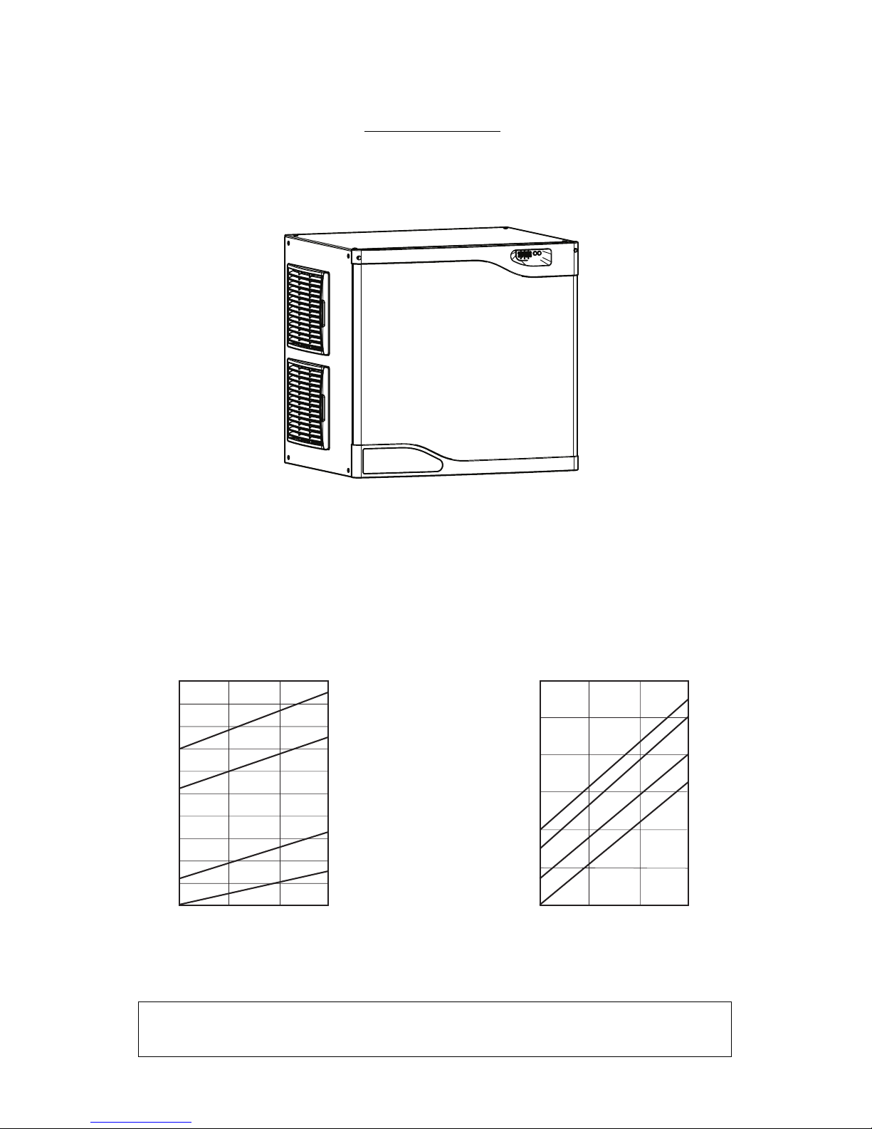
INTRODUCTION
This technical manual covers the New Prodigy MVP line.
All models are shipped with an Installation and User’s manual, which can be referred to separately.
General installation information is included in this manual.
Page 3
Page 3
Page 3
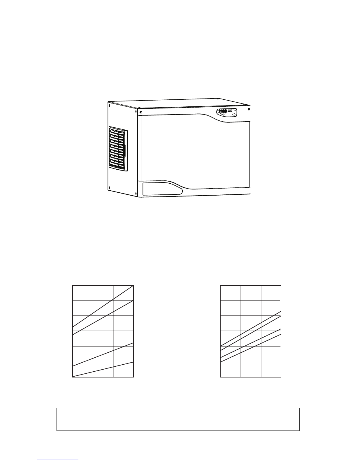
SPECIFICATIONS
MODULAR CUBER MVP 456
NOTE. To keep your Modular cuber performing at its maximum capacity, it is necessary to perform
periodic maintenance as outlined on last pages of this manual.
ice making capacity
ICE PRODUCED PER 24 HRS
Kg.
32
°C
15
10
AIR COOLED MODELS
WATER TEMPERATURE
AMBIENT TEMPERA TURE
°C
10
21
32
38
WATER COOLED MODELS
21
240
220
200
180
160
140
120
ICE PRODUCED PER 24 HRS
Kg.
32
°C
15
10
AMBIENT TEMPERA TURE
°C
10
21
32
38
21
255
235
215
195
175
155
135
WATER TEMPERATURE
Page 4
Page 4
Page 4
SPECIFICATIONS (CONT'D)
Model Cond. unit Finish Comp. HP
MVP 456 - MACHINE SPECIFICATIONS
Water req.
lt/24 HR
Model
Basic
electr.
amps
Start
amps
watts
Electric power cons.
Kwhx24 HR.
N. of wires
Amps
Fuse
220-240/50/1
MVP 456 - AS
MVP 456 - WS
3x1,5 mm
2
16
Cubes per harvest: 234 Full - 468 Half
* With water at 15°C
Stainless Steel 7/8
4.5
4.0
29
1000
850
23
19.5
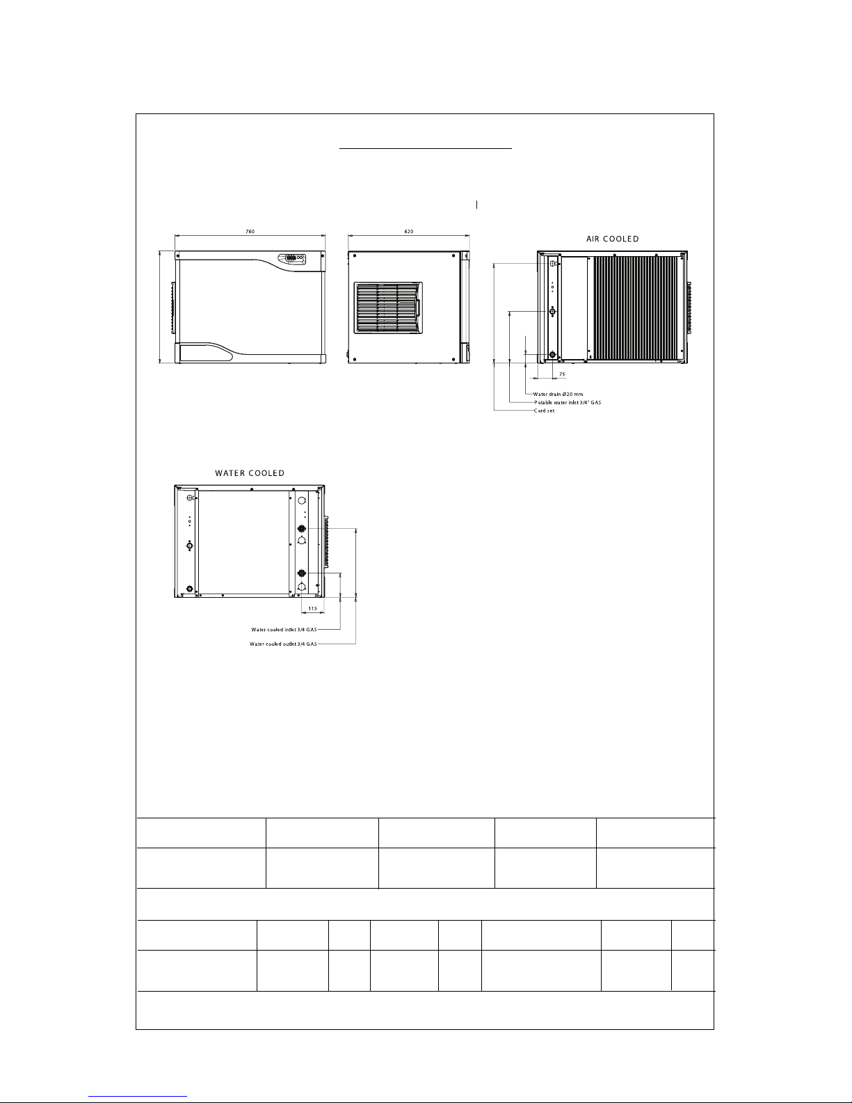
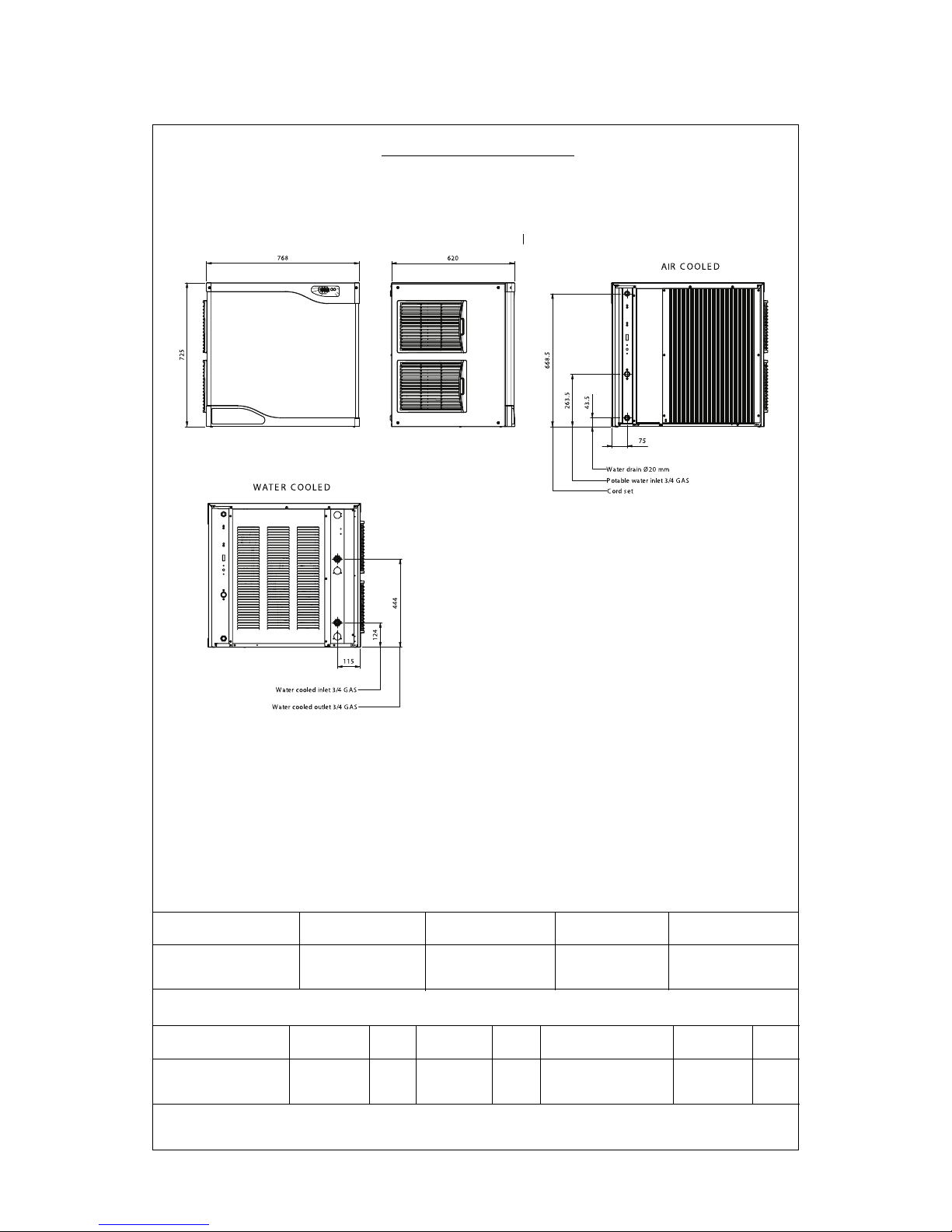
Dimensions:
HEIGHT 575 mm. (22" 1/2)
WIDTH 760 mm. (30")
DEPTH 620 mm. (24" 1/2)
WEIGHT 77 Kgs.
MVP 456 - AS Air 410*
MVP 456 - WS Water 2400*
Page 5
Page 5
Page 5
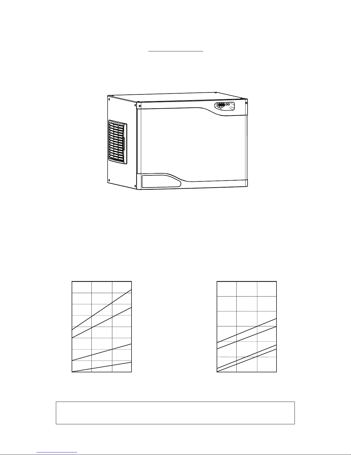
SPECIFICATIONS
MODULAR CUBER MVP 606
NOTE. To keep your Modular cuber performing at its maximum capacity, it is necessary to perform
periodic maintenance as outlined on last pages of this manual.
ice making capacity
Kg.
32
°C
15
10
°C
10
21
32
38
21
335
315
295
275
255
235
215
195
175
Kg.
32
°C
15
10
°C
10
21
32
38
21
335
315
295
275
255
235
215
ICE PRODUCED PER 24 HRS
AIR COOLED MODELS
WATER TEMPERATURE
AMBIENT TEMPERA TURE
WATER COOLED MODELS
ICE PRODUCED PER 24 HRS
AMBIENT TEMPERA TURE
WATER TEMPERATURE
Page 6

Page 6
Page 6
SPECIFICATIONS (CONT'D)
Model Cond. unit Finish Comp. HP
MVP 606 - MACHINE SPECIFICATIONS
Water req.
lt/24 HR
Model
Basic
electr.
amps
Start
amps
watts
Electric power cons.
Kwhx24 HR.
N. of wires
Amps
Fuse
220-240/50/1
MVP 606 - AS
MVP 606 - WS
3x1,5 mm
2
16
Cubes per harvest: 234 Full - 468 Half
* With water at 15°C
Stainless Steel 1 3/8 1 1/2
6,2
5,2
32
1300
1050
28
23
Dimensions:
HEIGHT 575 mm. (22" 1/2)
WIDTH 760 mm. (30")
DEPTH 620 mm. (24" 1/2)
WEIGHT 77 Kgs.
MVP 606 - AS Air 440*
MVP 606 - WS Water 2750*
Page 7
Page 7
Page 7
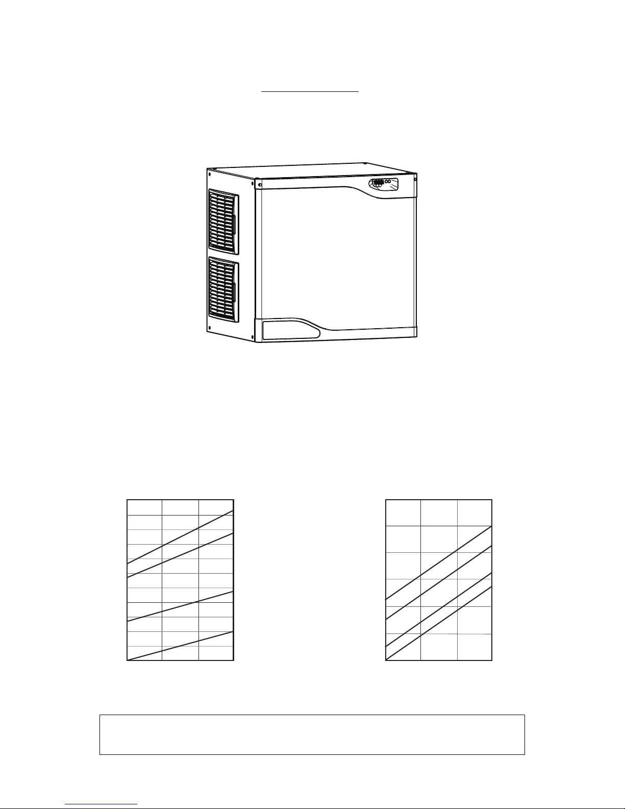
SPECIFICATIONS
MODULAR CUBER MVP 806
NOTE. To keep your Modular cuber performing at its maximum capacity, it is necessary to perform
periodic maintenance as outlined on the last pages of this manual.
ice making capacity
Kg.
32
°C
15
10
°C
10
21
32
38
21
445
425
405
385
365
345
325
305
285
265
245
225
Kg.
32
°C
15
10
°C
10
21
32
38
21
390
370
350
330
310
290
270
ICE PRODUCED PER 24 HRS
AIR COOLED MODELS
WATER TEMPERATURE
AMBIENT TEMPERA TURE
WATER COOLED MODELS
ICE PRODUCED PER 24 HRS
AMBIENT TEMPERA TURE
WATER TEMPERATURE
Page 8

Page 8
Page 8
MVP 806 - AS Air 580*
MVP 806 - WS Water 3900*
SPECIFICATIONS (CONT'D)
Model Cond. unit Finish Comp. HP
MVP 806 - MACHINE SPECIFICATIONS
Water req.
lt/24 HR
Model
Basic
electr.
amps
Start
amps
watts
Electric power cons.
Kwhx24 HR.
N. of wires
Amps
Fuse
MVP 806 - AS
MVP 806 - WS
3x1,5 mm
2
16
Cubes per harvest: 342 Full - 684 Half
* With water at 15°C
Stainless Steel 1 5/8 2.5
231
1850
1450
40
33.4
Dimensions:
HEIGHT 725 mm. (28" 1/2)
WIDTH 760 mm. (30")
DEPTH 620 mm. (24" 1/2)
WEIGHT 97 Kgs.
220-240/50/1
9.0
8.0
Page 9
Page 9
Page 9
SPECIFICATIONS
MODULAR CUBER MVP 1006
NOTE. To keep your Modular cuber performing at its maximum capacity, it is necessary to perform
periodic maintenance as outlined on the last pages of this manual.
ice making capacity
Kg.
32
°C
15
10
°C
10
21
32
38
21
475
455
435
415
395
375
355
335
315
295
275
Kg.
32
°C
15
10
°C
10
21
32
38
21
425
405
385
365
345
325
305
ICE PRODUCED PER 24 HRS
AIR COOLED MODELS
WATER TEMPERATURE
AMBIENT TEMPERA TURE
WATER COOLED MODELS
ICE PRODUCED PER 24 HRS
AMBIENT TEMPERA TURE
WATER TEMPERATURE
Page 10
Page 10
Page 10
MVP 1006 - AS Air 600*
MVP 1006 - WS Water 3800*
SPECIFICATIONS (CONT'D)
Model Cond. unit Finish Comp. HP
MVP 1006 - MACHINE SPECIFICATIONS
Water req.
lt/24 HR
Model
Basic
electr.
amps
Start
amps
watts
Electric power cons.
Kwhx24 HR.
N. of wires
Amps
Fuse
MVP 1006 - AS
MVP 1006 - WS
5x1,5 mm
2
10
Cubes per harvest: 342 Full - 684 Half
* With water at 15°C
224
1900
1600
41.3
37
Dimensions:
HEIGHT 725 mm. (28" 1/2)
WIDTH 760 mm. (30")
DEPTH 620 mm. (24" 1/2)
WEIGHT 104 Kgs.
380-400/50/3
Stainless Steel
2
3.5
3.3
Page 11

Page 11
Page 11
GENERAL INSTALLATION
Air or Water Cooled
Location Limitations:
The product is designed to be installed indoors,
in a controlled environment. Air cooled models
discharge very warm air into the room out the
back. Space must be allowed at the left side and
back for air intake and discharge. Water cooled
models discharge warm water into the building’s
drain. Space needs to be provided on both
sides and above for service access.
Space Limitations
Note: Although the machine will function, ice
capacity of air cooled machines will be
significantly reduced with minimal clearance
at the sides, back and top. Some space is
recommended for service and maintenance
purposes on all models.
15 cm (6") of space at the sides and back are
required for adequate operation. To get the most
capacity, locate the machine away from heat
producing appliances and heating ducts.
Airflow is in the left side, out the back (as viewed
from the front).
Environmental Limitations
Minimum Maximum
Air temperature 10°C (50F) 40°C (100F)
Water temperature 5°C (40F) 40°C (100F)
Water pressure 1 bar (14 psi) 5 bar (70 psi)
Power supply - acceptable voltage ranges
Minimum Maximum
115 104 126
230 207 253
Warranty Information
The warranty statement for this product is provided
separately from this manual. Refer to it for
applicable coverage. In general warranty covers
defects in material or workmanship. It does not
cover maintenance, corrections to installations,
or situations when the machine is operated in
circumstances that exceed the limitations printed
above.
Plumbing Requirements
All models require connection to cold, potable
water. A hand actuated valve within site of the
machine is required. Air cooled models have a
single 3/4" male inlet water connection.
Water cooled models have the same inlet fitting
plus an additional 3/4" male condenser inlet
water connection.
WATER
The quality of the water supplied to the ice
machine will have an impact on the time between
cleanings and ultimately on the life of the product.
There are two ways water can contain impurities:
in suspension or in solution. Suspended solids
can be filtered out. In solution or dissolved
solids cannot be filtered, they must be diluted or
treated. Water filters are recommended to
remove suspended solids. Some filters have
treatment in them for suspended solids. Check
with a water treatment service for a
recommendation.
RO water. This machine can be supplied with
Reverse Osmosis water, but the water
conductivity must be no less than 10
microSiemens/cm.
Potential for Airborne Contamination
Installing an ice machine near a source of yeast
or similar material can result in the need for
more frequent sanitation cleanings due to the
tendency of these materials to contaminate the
machine. Most water filters remove chlorine
from the water supply to the machine which
contributes to this situation. Testing has shown
that using a filter that does not remove chlorine
will greatly improve this situation, while the ice
making process itself will remove the chlorine
from the ice, resulting in no taste or odor impact.
Additionally, devices intended to enhance ice
machine sanitation can be placed in the machine
to keep it cleaner between manual cleanings.
Water Purge
Cube ice machines use more water than what
ends up in the bin as ice. While most water is
used during ice making, a portion is designed to
be drained out every cycle to reduce the amount
of hard water scale in the machine. That’s
known as water purge, and an effective purge
can increase the time between needed water
system cleaning.
In addition, this product has the capability to
automatically vary the amount of water purgeed
based on the purity of the water supplied to it.
The water purge rate can also be set manually.
Adjustments of purge due to local water
conditions are not covered by warranty.
Page 12

Page 12
Page 12
Water Filters
If connecting to water filtration, filter only the
water to the reservoir, not to the condenser.
Install a new cartridge if the filters were used with
a prior machine.
All models require drain tubing to be attached to
them. Air cooled models have a single 21mm
O.D. male drain fitting in the back of the cabinet.
Water cooled models have the same fitting plus
an additional 3/4" male drain fitting in the back of
the cabinet.
Note: This NSF listed model has a 1" antiback flow air gap between the water inlet
tube end and the highest possible reservoir
water level, no back flow device is required
for the potable water inlet.
Drain Tubing:
Use rigid drain tube supplied with machine and
route them separately - do not Tee into the bin’s drain.
Horizontal runs of drain tubing need a 1/4" fall per
foot of run for proper draining.
Follow all applicable codes.
Electrical
See the spec sheet or User’s Manual for Wire
Size and Maximum Fuse Size ratings.
The machine is supplied with a 1,5 meter length
power cord.
Install the electrical plug accordingly to the local
standard needed.
The dataplate on the back of the cabinet details
the power requirements, including voltage,
phase, minimum circuit ampacity and maximum
fuse size. Extension cords are not permitted. Use
of a licensed electrician is recommended.
Follow all applicable local, state and national
codes.
Page 13

Page 13
Page 13
ADJUSTMENTS
Ice Bridge Thickness
Caution: Do not make the bridge too thin or
the machine will not harvest properly. Bridge
thickness adjustments are not covered by
warranty.
Shut machine off.
Access the ice thickness sensor.
Check gap between metal tip and evaporator
grid. Small cube standard gap is 5 mm (3/16"),
medium cube standard gap is 5,5 mm (7/32"). To
set, place a 5 mm - 3/16" (small cube) or 5,5 mm
- 7/32" (medium cube) drill bit between sensor tip
and evaporator to check. Adjust gap using
adjustment screw.
Restart unit and check ice bridge. Repeat as
needed.
WATER PURGE SETTING
The water purge is factory set to the Automatic setting. The setting can be changed to one of 5 manual
settings or placed on automatic. The purge setting shows in the Code Display.
To set:
Switch the machine OFF by holding the Off
button in until a number or the letter A shows on
the display.
Press and release the On button repeatedly until
the number on the display corresponds to the
desired setting.
Press and release the Off switch again to return
to the normal control state.
(very soft
≤ 4°f)
Soft
water
(5 ≤ °f ≤ 9)
(10 ≤ °f ≤ 16)
Hard
water
(17 ≤ °f ≤ 22)
Very hard
water
(
°f ≥ 23)
Page 14

Page 14
Page 14
PRODIGY CUBER SYSTEM
INFORMATION
Overall System Type:
• Refrigeration: Mechanical, either air cooled,
water cooled.
• Water System: Inlet water solenoid valve fills
reservoir once per cycle. Purge solenoid valve
opens to discharge some reservoir water once
per cycle.
• Control System: Electronic
• Harvest cycle sensor: Conductivity probe
• Water full/empty sensor: Conductivity probe
• Bin Control: Curtain Switch
• Ice type: Unified
• Harvest system: Hot gas defrost with mechanical
assist
Electrical Components:
• Compressor
• Contactor
• Water Pump
• Inlet Water Solenoid Valve
• Purge or purge Valve
• Fan Motor(s)
• Fan motor pressure control
• High pressure cut out
• Harvest Assist Solenoid
• Hot Gas Valve
• Controller
• Transformer - 12v AC for the controller only
• Water Level Sensor
• Ice Thickness Sensor
• Curtain Switch
CONTROLLER INFORMATION
Machine Indicator Lights
• Power
• Status
• Water
• Clean
Code Display
Main codes - automatically displayed
F Freeze Cycle
F flashes Freeze Cycle is Pending
H Harvest Cycle
H flashes Manual Harvest
b Binis Full
C Clean Cycle
L Board Locked
d Test Mode
O Off
E Self Test Failed
1 flashes Max Freeze - Retrying
1 Max Freeze Time Shut Down
2 flashes Max Harvest - Retrying
2 Max Harvest Time Shut Down
3 Slow Water Fill
4 High Discharge Temp
5 Sump Temp Sensor Failure
7 Discharge Temp Sensor Failure
8 flashes Short Freeze - Retrying
8 Short Freeze - Thin ice
Setting Codes - requires push button sequence for access
Water Purge Settings
A, 1, 2, 3, 4, 5
De-scale Interval Settings
6, 5, 3, 3
CONTROLLER INFORMATION
Component Indicator Lights
• Condenser Fan
• Water Pump
• Purge Valve
• Water Solenoid
• Hot Gas
• Compressor
• Ready to Harvest
• Sump Empty
• Sump Full
• Curtain SW1
• Curtain SW2 (not used)
Page 15

Page 15
Page 15
HOW IT WORKS - AIR COOLED
Freeze Cycle. At start up the controller drains
and refills the reservoir. The reservoir refills
when the mid length water level sensor probe is
uncovered and continues to fill until the top probe
is in contact with water. When the reservoir has
filled, the compressor and water pump start.
After the discharge pressure has increased past
the cut in point of the fan pressure control, the fan
motor(s) will begin to operate and warm air will be
discharged out the back of the cabinet. The fan
motor will switch on and off as the discharge
pressure rises and falls. Water flows over the
evaporator as the refrigeration system begins to
remove heat. When the water temperature falls
to a preset point, as measured by the water
temperature sensor, the controller shuts off the
water pump for 30 seconds. The freeze cycle
resumes when the pump restarts and ice begins
to form on the evaporator. As it forms, the water
flowing over the ice moves closer and closer to
the metal tip of the ice thickness sensor. When it
comes into contact with the sensor for a few
continuous seconds, that signals the controller
that the freeze cycle is complete.
The controller may shut the air cooled fan motor
off for a variable period of time to build up heat for
harvest. This is dependant upon the temperature
of the discharge line sensor.
Harvest Cycle. When the harvest cycle begins,
the controller shuts off the fan motor, switches on
the hot gas valve, and through a parallel circuit,
the harvest assist solenoid. After a few seconds
the purge valve opens and water is drained from
the reservoir. Based on either the automatic
purge or manual purge setting, the pump and
purge valve will be switched off at a time
determined to have drained enough water for
that setting. The inlet water valve will open to fill
the reservoir anytime the mid length probe is
uncovered, which occurs during the reservoir
drain cycle. Harvest continues as the hot
discharge gas flows into the evaporator
serpentine, heating up the evaporator. At the
same time the harvest assist solenoid is pushing
against the back of the ice slab. When the ice
releases from the evaporator, it harvests as a
unit, and the harvest assist probe provides some
additional force to push it off. When the ice falls
off it will force the curtain open. An open curtain
during the harvest cycle signals the controller
that the evaporator has released its ice terminating
harvest. If the curtain remains open, the controller
will shut the machine at bin full. Anytime harvest
is complete the hot gas valve and harvest assist
solenoid are shut off. The harvest assist solenoid
pin returns to its normal position by spring
pressure.
If the curtain re-close after harvest, the freeze
cycle will restart.
HOW IT WORKS - WATER COOLED
Freeze Cycle. At start up the controller drains
and refills the reservoir. The reservoir refills
when the mid length water level sensor probe is
uncovered and continues to fill until the top
probe is in contact with water. When the reservoir
has filled, the compressor and water pump start.
After the discharge pressure has increased past
the set point of the water regulating valve, the
water regulating valve will open and warm water
will be discharged out the condenser drain. The
water regulating valve will modulate to maintain
a relatively constant discharge pressure. Water
flows over the evaporator as the refrigeration
system begins to remove heat. When the water
temperature falls to a preset point, as measured
by the water temperature sensor, the controller
shuts off the water pump for 30 seconds. The
freeze cycle resumes when the pump restarts
and ice begins to form on the evaporator. As it
forms, the water flowing over the ice moves
closer and closer to the metal tip of the ice
thickness sensor.
When it comes into contact with the sensor for a
few continuous seconds, that signals the
controller that the freeze cycle is complete.
Harvest Cycle. When the harvest cycle begins,
the controller switches on the hot gas valve, and
through a parallel circuit, the harvest assist
solenoid. After a few seconds the purge valve
opens and water is drained from the reservoir.
Based on either the automatic purge or manual
purge setting, the pump and purge valve will be
switched off at a time determined to have drained
enough water for that setting. The inlet water
valve will open to fill the reservoir anytime the
mid length probe is uncovered, which occurs
during the reservoir drain cycle. Harvest
continues as the hot discharge gas flows into the
evaporator serpentine, heating up the evaporator.
At the same time the harvest assist solenoid is
pushing against the back of the ice slab. When
the ice releases from the evaporator, it harvests
as a unit, and the harvest assist probe provides
some additional force to push it off. When the ice
falls off it will force the curtain open. An open
curtain during the harvest cycle signals the
controller that the evaporator has released its ice
terminating harvest. If the curtain remains open,
the controller will shut the machine at bin full.
Anytime harvest is complete the hot gas valve
and harvest assist solenoid are shut off.
The harvest assist solenoid pin returns to its
normal position by spring pressure.
If the curtain re-close after harvest, the freeze
cycle will restart.
ELECTRICAL SEQUENCE
Air or Water Cooled
Power connected, unit previously switched Off.
Control board does a self check. If the self check
fails, the unit displays an E and no further action
will occur.
If the self check passes, the controller will display
a 0, the curtain light will be ON and the Power
and Sump Empty lights will be ON.
Pushing and releasing the On button will start
the ice making process.
Page 16

Page 16
Page 16
The display will begin to blink F. The component
indicator lights will switch on and off to match
the following process:
The purge valve opens and the water pump
starts to empty the reservoir. This is done to
discharge any excess water from ice melting into
the reservoir.
The hot gas valve and the harvest assist solenoid
are energized.
The inlet water valve will open to fill the reservoir.
The water valve can open any time the water
level is low.
After a few seconds the purge valve closes and
the pump shuts off.
When the reservoir is full the inlet water valve
stops and the compressor switches on. Five
seconds after the compressor starts the hot gas
valve and the harvest assist solenoid are deenergized.
Light Information: The display shows a nonblinking F. The Power and Status Lights will be
Green. The compressor, fan motor, water
pump, sump full and the curtain switch lights
will be ON.
The air cooled model’s fan motor will start to turn
when the discharge pressure has built up to the
fan pressure control’s cut in point. This is about
15 seconds after the compressor starts.
The Freeze cycle continues. The compressor,
water pump, fan motor and curtain indicator
lights will be ON. When the reservoir water
temperature falls to a certain preset point, the
water pump will shut off for 30 seconds. This is
the anti-slush period. At this time the controller
checks the conductivity of the water in the
reservoir for the auto-purge feature. After the
water pump restarts the Sump Full light will go
out and neither sump lights will be on for the rest
of the freeze cycle.
When the ice has built up enough so that the
water flowing over the evaporator comes into
continuous contact with the ice level sensor, the
Ready to Harvest light will begin to blink on and
off. When it has been On continuously for 3
seconds, the controller will switch the machine
into a Harvest cycle.
ELECTRICAL SEQUENCE
Air or Water Cooled
Indicator Information: The display shows a
non-blinking H. The Power and Status Lights
will be Green. The compressor, hot gas valve
and one curtain switch lights will be ON. After
a few seconds the water pump, purge valve
and inlet water valve lights will come on.
The fan motor(s) shut off and remain off
throughout the harvest cycle.
The harvest assist solenoid is connected in
parallel with the hot gas valve. Although it is
energized throughout the harvest cycle, its piston
does not move until the ice has become partially
loosened from the evaporator plate by the action
of the hot refrigerant gas passing through the
evaporator serpentine.
The water pump and purge valve will shut off
when the purge level setting time has been
reached, either the manual time or the automatic
time. The inlet water valve will remain on until it
fills the reservoir. The Ready to Harvest light will
switch Off when the ice falls from the evaporator.
Harvest continues until the ice slab is ejected
from the evaporator and falls, opening the curtain.
When the curtain opens, the magnetic reed curtain
switch opens, breaking the circuit to the controller.
If the curtain re-closes within 30 seconds, the
controller switches the machine back into another
freeze cycle. If the curtain switch remains open,
the controller shuts the machine down at bin full.
ELECTRICAL COMPONENT DETAIL
Compressor
• Operated by the compressor contactor. Single
or three phase.
Contactor
• Operated by the controller and the high pressure
cut out switch. Line voltage coil. When energized
the Compressor indicator light will be ON.
Water Pump
• Operated by the controller. When energized,
the Water Pump indicator light will be ON.
Inlet Water Solenoid Valve
• Operated by the controller. Line voltage coil.
When energized, the Water Solenoid indicator
light will be ON.
Purge Valve
• Operated by the controller. Line voltage coil.
When energized, the Purge Valve indicator
light will be ON. Energized for a time during
harvest.
Fan Motor(s)
• Operated by the controller and the fan pressure
control. Can cycle on and off in the freeze cycle,
always off during harvest. When the controller
has energized it, the indicator light will be ON
but the fan will not turn unless the discharge
pressure is high enough to close the high
pressure control.
• Fan(s) may shut off near the end of the freeze
cycle to build up heat for harvest. Time of shut
off depends upon available heat, as measured
by the discharge temperature.
High pressure cut out
• Some air cooled and all remote and all water
cooled models have a high pressure cut out
switch that shuts the power off to the compressor
contactor if the discharge pressure is too high.
It is an automatic reset.
Page 17

Page 17
Page 17
Harvest Assist Solenoid
• Operated by the controller in parallel with the
hot gas valve. Cycles on and off at the beginning
of a restart. Energized throughout the harvest
cycle. Line voltage coil.
Hot Gas Valve
• Operated by the controller in parallel with the
harvest assist solenoid. Cycles on and off at
the beginning of a restart. Energized throughout
the harvest cycle. Line voltage coil.
Controller
• Senses ice thickness, water level, water temperature, discharge temperature. Controls
compressor contactor, fan motor, water pump,
inlet water valve, hot gas valve, purge valve,
harvest assist solenoid. Indicates status and
component operation. 12 volt.
Transformer
• 12 volt secondary, supplies power to controller
only.
Water Level Sensor
• Three probe conductivity sensor. Bottom probe
is common, mid probe is refill sump, top probe
is full sump. Refill can occur at any time.
Ice Thickness Sensor
• Single wire conductivity sensor. Circuit made
from controller to ground to controller when
water contacts a probe suspended over ice
plate. Signals ready for harvest.
Curtain Switch
• Magnetic reed switch. Normally open, switch is
closed when magnet is nearby and can be
connected to either J8 or J7 of controller.
Curtains may be removed in the freeze cycle
without affecting controller operation. A curtain
removed during harvest will cause the controller
to terminate harvest and shut the unit off. If it
remains open for 30 seconds that signals the
controller to shut the unit off at bin full.
Water temperature sensor.
• Thermistor inserted into the water pump
discharge hose. Reported temperature used
by the controller to determine anti-slush cycle
start time.
Discharge temperature sensor.
• Thermistor attached to the discharge line near
the compressor. Reported temperature used
by the controller to determine end-of-cyclefan-off-delay time. If discharge temperature
exceeds a preset maximum, controller will shut
the machine off.
Note: Controller will operate machine in a
default mode with thermistors disconnected
from the controller. Diagnostic code #3 will be
displayed during that time.
Component Indicator Light Table
SYSTEM INDICATOR LIGHT ON
Condenser Fan or Liquid Line Valve Fan Motor Powered or LLV open
Water Pump Pump Motor Powered
Purge Valve Purge Valve Opens
Inlet Water Solenoid Valve Inlet Water Valve Opens
Hot Gas Hot Gas Valve Opens
Compressor Contactor Contactor Closes
Ready to Harvest Water contacting ice thickness sensor probe
Sump Empty Open between mid sensor and common
Sump Full Closed between top probe and mid probe
Curtain Switch Curtain open
Page 18

Page 18
Page 18
REFRIGERATION
Refrigerant: R-404A
Compressors: Copeland or Tecumseh hermetic
by model
Expansion valves: Non adjustable, internally
equalized.
Hot gas valve: Pilot operated, line voltage coils.
Condensers: Forced draft air, counterflow water.
All air cooled models have left side air inlet.
All air cooled models exhaust air out the back.
Air filters: Surface mounted to left side panel.
Filter media removable without removing panel.
Fan blades: Reduced vibration blades in most
air cooled models.
Fan pressure control. All AC. Controls fan
motor operation in the freeze cycle.
High pressure cut out. WC, AC.
Evaporator: Unified cell plate. Nickel plated
copper. Two heights: 12" and 18". Small cube =
half dice, medium cube = full dice.
Small cube: 22 mm high x 22 mm deep x 9,5 mm
high (7/8" high x 7/8" deep x 3/8" high).
Medium cube: 22 mm high x 22 mm deep x
22 mm high (7/8" high x 7/8" deep x 7/8" high).
WATER SYSTEM
Batch type. Water reservoir contains full water
charge for each ice making cycle.
Water valve: Solenoid type. Opens to fill reservoir
when mid sensor probe no longer makes a circuit
to the bottom probe. Closes when reservoir is full
and top probe makes circuit to mid probe.
Pump: Unsealed pedestal type, S.S. side
mounting bracket
Water purge valve: Solenoid type. Opens to
purge water during harvest cycle.
Water Level Sensor: Three probe conductivity.
Distributor: ABS plastic. Evenly distributes water
over the evaporator surface. Slides off the
evaporator top. Removable cover for ease of
cleaning.
Page 19

Page 19
Page 19
CONTROL OPERATION
Standard control:
• Electronic controller operating from a 12 AC volt
power supply. Will operate within a voltage
range between 10 and 15.5.
• User’s Indicator lights, four front visible: Power,
Status, Water, De-scale/Sanitize.
• Accessible On switch.
• Accessible Off switch.
• Code Display: Displays letters and numbers to
indicate cycles and diagnostic codes.
• Manual Harvest switch: Use to trigger harvest at
any time.
• Clean switch: Use to initiate and finish the descale or sanitizing cycles.
• Component Operation Indicator Lights: Indicate the status of certain components; water
level; ready for harvest; curtain switch position.
• Power Light: On when power is being supplied
to the controller.
• Status Light: Green when machine is in ice
making mode and is operating correctly. Blinks
red when a machine malfunction has been
detected.
• Water Light: Blinks red when reservoir does not
fill with allowed time period.
• De-scale / sanitize: Yellow when the controller
has determined it is time to de-scale and sanitize
the machine. Use clean process to reset light.
Time is determined by power up time and
controller’s setting. Standard setting is 6
months. See adjustment process
Controller Connections:
• J1 - Ground and Power Supply
• J2 - High voltage power harness to loads
• J3 - Factory use
• J4 - Optional board connector
• J5 - Communications port
• J6 - Thermistor connection
• J7 - Curtain switch
• J8 - Curtain switch
• J9 - Water level sensor
• J10 - Ice thickness sensor
• J11 - Bin thermostat. Use with NO thermostat
(closes on temperature fall) & specified harness.
CONTROL SAFETIES
Max freeze time - 45 minutes
When exceeded, control shuts the unit off for 50
minutes and will attempt a restart. If the condition
is exceeded again the next cycle, the control will
shut the unit off for 50 minutes and attempt a
restart. If it fails a third consecutive time the
controller will shut the machine down and must
be manually reset.
Min freeze time - 6 minutes
If the controller switches the machine into harvest
within 20 seconds of the minimum freeze time,
the controller will harvest for a preset time and
does not stop if the curtain switch opens.
If this occurs again in the next three cycles, the
machine will shut down and must be manually
reset.
Max harvest time - 3 minutes
If the harvest cycle has continued for 3 minutes
without the curtain opening, the controller will
shut the machine off for 50 minutes and then
restart. If there is another the machine will shut
the machine off for another 50 minutes and then
restart. If it fails a third consecutive time the
controller will shut the machine down and must
be manually reset.
• Time between resets - 50 minutes
• Number of automatic resets - 2
• Max water fill time - 5 minutes. Machine will
attempt a restart every 20 minutes.
• Max discharge temp - 120°C (250 degrees F).
• Time interval between cleanings - 6 months
power on time - adjustable in one month
increments, can be set at 6, 5, 4 or 3 months of
power up time.
• Manual harvest time - 3 minutes
• Minimum compressor off time - 4 minutes
• Continuous Run Time Maximum Cycles - 25
RESTARTS
Power Interruption
The controller will automatically restart the ice
machine after adequate voltage has been
restored.
• H blinks on code display
• Status indicator light blinks
• Reservoir is drained and refilled
• Default harvest is initiated. The curtain switch
does not have to open to terminate harvest,
harvest will continue until either the curtain’s
switch opens or the default harvest time expires.
Default harvest time is 2 and half minutes. The
machine will then return to a normal freeze
cycle.
Water Interruption
• The controller will attempt to fill the reservoir
every twenty minutes until it is successful.
On-Off Switch Access
All models ship with the On and Off switches front
accessible.
Page 20

Page 20
Page 20
CONTROL BUTTON USE
(from standby)
Set purge level, 1-5 (1 is minimum, 5 is maximum)
or Automatic:
• Hold off button in till a number or the letter A
shows on display and green STATUS led
ON. . Release.
• Press and release the On button to cycle through
and select one of the five purge settings (1->5)
or to use the Automatic setting (A).
Recall diagnostic code:
• Hold off button in till a number or the letter A
shows on display and green STATUS led
ON. . Release.
• Press and release the Harvest button to cycle
through each of the last 10 error codes from
most recent to oldest.
Clear diagnostic code:
• Hold Clean and Harvest buttons in for 3 seconds
to clear all prior codes.
Reset control:
• Depress and release Off, then depress
andrelease On.
Start Test Mode:
• Hold off button in till a number or the letter A
shows on display and green STATUS led
ON. . Release.
• Hold Clean button in till letter d shows on
display. Release.
Lock / Unlock control:
• Hold On button in for 3 seconds, keep holding
then press and release Off twice.
Empty reservoir:
• Hold Clean button in till dash (-) shows on
display. Release. Pump and purge valve will be
ON for 30 seconds. Repeat as needed.
Test Mode: See next page for Air and Water
Cooled mode.
• Hold off button in till a number or the letter A
shows on display and green STATUS led ON,
release. Then depress Clean for 3 seconds till
letter d shows on display.
• The sump will fill the first 30 seconds of the test.
If the sump is full it will overflow into the bin. At
30 seconds the WIV will shut off and the WP will
turn on. You will be able to see and hear the
water running over the plate. After 10 seconds
the PV and HGV will turn on. Water will be
purging from the machine. After 10 more
seconds the compressor will start. 5 seconds
later the HGV will close. The compressor will
run for a total of 20 seconds. After which
everything will turn off for 5 seconds. After that
time the HGV will open and you’ll be able to
hear the hissing as the pressure is equalized.
10 seconds later the fan will turn on (if air
cooled). After 10 seconds all will be off and the
output test will be complete.
Change De-Scale Notification Interval
Like the others, this feature is accessible only
from standby (Status Light Off).
• Press and hold harvest button till a number
shows on display.
• This will allow control to enter Time to Clean
Adjustment State.
• Display current time to clean months on 7
segment display.
• Pressing clean button repeatedly will cycle
through one of 4 possible settings:
6 months (4380 hours) (default)
5 months (3650 hrs)
4 months (2920 hrs)
3 months (2190 hrs)
Time (seconds) On Off
0 WIV -30 seconds WP, HGV, Comp, Fan, PV
30 WP -10 seconds WIV, HGV, Comp, Fan, PV
40 WP, PV, HGV -10 seconds WIV, Comp, Fan
50 HGV, Comp -5 seconds WIV, WP, Fan, PV
55 Comp -15 seconds WIV, HGV, WP, Fan, PV
70 None -5 seconds All
75 HGV -10 seconds WIV, WP, Comp, Fan, PV
85 Fan -10 seconds WIV, HGV, WP, Comp, PV
95 None All - Test Complete
Test Mode Sequence Table - Air or Water Cooled
Page 21

Page 21
Page 21
Disch. Disch. Hi Suction Suction Amps Amps
Pressure Pressure Pressure Pressure Pressure
Compressor Compressor
Freeze max Freeze min CUT OUT Beginning end Freeze Beginning end
bar bar bar Freeze bar bar Freeze Freeze
MVP 456 A - 230/50/1
17,5 15,5 33 3,5 2,0 15 4,7 3,6
MVP 456 W - 230/50/1
16,5 16,5 33 3,5 2,2 16 4,2 3,4
MVP 606 A - 230/50/1
18 16 33 2,7 1,5 13 6,2 4,8
MVP 606 W - 230/50/1
16,5 16,5 33 3,2 1,7 13 5,8 4,5
MVP 806 A - 230/50/1
18,5 16,5 33 2,0 1,8 12,5 8,6 6,4
MVP 806 W - 230/50/1
16,5 16,5 33 3,5 1,9 14,5 9,0 6,7
MVP 1006 A - 400/50/3
16 14 33 2,9 1,6 12 3,7 3,0
MVP 1006 W - 400/50/3
16,5 16,5 33 3,2 1,8 13,5 3,6 2,8
Cycle time
minutes
MODEL
Refrigerant charge R 404 A - gr.
MODEL MVP 456 MVP 606 MVP 806 MVP 1006
Air cooled 700 850 1300 1600
Water cooled 500 550 650 1200
Refrigerant metering device
Thermostatic expansion valve.
SERVICE SPECIFICATION
In servicing a machine, it is often, useful to
compare that individual units operating
characteristics to those of a normally operating
machine. The data that follows gives those
characteristics; however, be aware that these
values are for NEW, CLEAN machine operating
at 21 °C ambient and 15 °C water. USE THESE
NUMBERS AS A GUIDELINE ONLY.
OPERATING CHARACTERISTICS
On air-cooled models during the freezing cycle,
the discharge pressure is maintained between
two preset values by means of fan control
(condenser sensor); and at the same time, the
suction pressure will also decline reaching it’s
lowest point just before harvest. Compressor
amps experience a similar drop.
On water-cooled, the discharge pressure is
constantly, maintained during the freeze cycle by
the water regulating valve. However, suction
pressure and compressor amps, will still decline
as the machine freezes ice.
NOTE: Always check nameplate on individual
icemachine for special refrigerant charge
before charging the refrigeration system.
Such refrigerant charge is the average charge
for the MVP Modular Cubers. However it is
important to check nameplate for each
machine.
Page 22

Page 22
Page 22
DIAGNOSIS
No ice
Problem Likely Cause Probable Solution
No power to unit Power disconnected Check breaker or fuse. Reset or
replace, restart and check
No power to controller Transformer open Replace transformer
Shut down on maximum Water shut off Restore water supply
water fill time
Shut down on maximum Water leak Check purge valve, curtain,
freeze time sump, pump hose
Air filters clogged Clean air filters
Dirty condenser Clean condenser
Restricted location, intake air too hot
Have machine moved
Ice thickness sensor dirty or Check ice thickness sensor probe
disconnected
Water distributor dirty Remove and clean water distributor
Inlet water valve leaks through Check inlet water valve
during freeze
Connected to hot water Check for bleed thru from / missing
check valve in building water supply
Incomplete harvest Check harvest system
High pressure cut out opened Check fan motor pressure control,
check fan motor, check controller
using test mode
Fan motor pressure control open Check fan pressure control
Fan motor not turning Check fan motor, check fan blade,
check controller using test mode
Water pump not pumping Check pump motor, check controller
using test mode
Shut down on maximum Pump hose disconnected Check hose
freeze time
Check compressor contactor,
check controller using test mode
Compressor not operating Check compressor start components
Check compressor voltage
Check compressor windings
Low refrigerant charge Add some refrigerant and restart unit.
If cycle time improves, look for leak.
Hot gas valve leaks through during Check hot gas valve for hot
freeze outlet during freeze
Thermostatic expansion valve Check bulb
bulb loose
Thermostatic expansion valve Check evaporator superheat,
producing very low or very high change TXV if incorrect
superheat
Compressor inefficient
Check compressor amp draw, if low and
all else is correct, change compressor
Page 23

Page 23
Page 23
Problem Likely Cause Probable Solution
Shut down on maximum Ice bridge thickness too small, Check and adjust if needed
harvest time not enough ice to open curtain
Ice bridge thickness too large, Check and adjust if needed
ice frozen to evaporator frame
Purge valve does not open, water Check purge valve
melts ice bridge, not enough ice to
open curtain
Incomplete ice formation Check water distributor for partially
plugged holes
Curtain out of position Check curtain for swing restriction
Curtain switch does not open when Check switch with ohmmeter
curtain does
Machine in very cold ambient Move machine to a warmer location
Hot gas valve does not open Check hot gas valve, check controller
using test mode
Harvest assist probe out of position -
Check harvest assist mechanism ejector pin not retracted spring should retract pin
Damaged evaporator Check evaporator surface
Fan motor stays on during harvest Check controller using test mode
Shut down on minimum Grounded ice thickness sensor Check sensor for dirt and position.
freeze time
Clean and check gap to evaporator surface.
Long freeze cycle Dirty air filters Clean filters
Dirty condenser Clean condenser
Hot ambient Reduce room air temperature
Water leak Check purge valve, check curtain
Water inlet valve leaks through Check inlet valve
Low on refrigerant Add refrigerant, if cycle time drops,
check for leak
Incorrect superheat Check evaporator superheat, if
significantly low or high, replace TXV
Fan(s) cycle on and off Check pressures fans cycle at.
Replace fan pressure switch if too low
Long Harvest Cycle Dirty evaporator De-scale water system
No harvest assist Check harvest assist solenoid
Bridge thickness too big Check and adjust bridge thickness
Machine in very cool ambient Increase room temperature
False bin full signal
Ice jammed in between curtain and sump
Clear ice away
Curtain does not close correctly Check curtain for proper swing
Fan blade vibrates Blade is bent Replace fan blade
Fan motor mount is broken Replace motor mount
Compressor vibrates Mounting bolts loose Tighten bolts
Water pump vibrates Pump bearings worn Replace pump
Panels vibrate Mounting screws loose Tighten screws
DIAGNOSIS
Page 24

Page 24
Page 24
TEST PROCEDURES
All electrical components in this ice machine can
be diagnosed with a volt-ohmmeter.
Curtain Switch:
1. Test using the controller’s indicator lights.
Observe SW1 or SW2. Open and close the
curtain in question. When the curtain is opened,
the SW light will be ON. When the curtain gets to
within a half inch of closing (at the switch) the SW
light will go OUT.
Note. As the Prodigy MVP series is equipped
with just one Curtain Switch, it’s normal to
have one SW led always ON.
2. Test with an ohmmeter. Disconnect electrical
power. Open the control box cover. Unplug the
curtain switch lead from the controller. Connect
an ohmmeter to the leads of the switch. Open
and close the curtain. When the curtain is closed,
the switch is closed and there will be continuity.
When the curtain is open, the switch is open and
the circuit will be open.
3. Test the controller’s curtain switch circuit by
jumping the connectors on J1 or J2 together.
Reconnect electrical power. When jumped, the
matching SW light will go out. When unplugged
or open, the SW light will be ON.
ICE THICKNESS SENSOR
1. Test using the controller’s indicator light.
Observe the Ready To Harvest light. Shut the
machine off. Use a wire to connect the metal part
of the Ice Thickness sensor to the evaporator or
simply remove the Ice Thickness Sensor and
touch its metal surface to the metal control box
wall. The Ready for Harvest light should go ON.
2. Test with an Ohmmeter. Disconnect electrical
power. Open the control box cover. Unplug the
ice thickness sensor lead from the controller.
Connect an ohmmeter lead to the ice thickness
sensor lead, touch the other ohmmeter lead to
the ice machine chassis. There must be an open
circuit. If there is continuity, the sensor must be
replaced. If there is no continuity, touch the
ohmmeter lead to the metal part of the ice
thickness sensor. There should be continuity. If
open, check the ice thickness sensor for scale
build up. Clean and recheck. If still open, replace
the ice thickness sensor.
3. Test the controller’s ice thickness sensor
circuit by connecting a wire from J10 to ground.
Reconnect electrical power. The Ready for
Harvest light should go ON
WATER LEVEL SENSOR
1. Test using the controller’s indicator lights
(sump empty and sump full). Unit must be powered
up and there must be water in the sump. Add
some manually if needed. Locate water level
sensor. Release from sump cover and slowly lift
up until the mid-length probe is out of the water.
The sump empty light should come on, and if the
unit is on the inlet water solenoid valve will open
to fill the reservoir. Return the water level sensor
to its normal position. If the unit is on and calling
for ice the water will fill until the top probe is in
contact with it, at that time the sump full light will
switch ON.
2. Test with an ohmmeter. Disconnect electrical
power. Open the control box cover. Unplug the
connector at J9. Locate water level sensor and
Page 25

Page 25
Page 25
remove it from the sump cover. Test 1: Place one
lead of the ohmmeter on the longest probe and
the other on the controller end of the red wire,
there should be continuity. Test 2: Place one lead
on the controller end of the white wire and the
other on the mid-length probe, there should be
continuity. Test 3: Place on lead on the controller
end of the black wire and the other on the
shortest probe, there should be continuity.
If not, clean the probes and recheck.
3. Test the controller’s water level sensor circuit.
Reconnect electrical power. Unplug harness from
water level sensor, the sump empty light should
be ON. Jump harness wires white and black. The
sump full light should be ON. Jump harness
wires black and red, the sump full and sump
empty lights will be OFF. Check harness wire by
wire for continuity if there is no reaction from the
controller during this test.
TEMPERATURE SENSOR
1. Check controller. If the sensor calibration is
completely out of range, the code display will
read either 5 or 7.
2. Check with an ohmmeter. Open control box
cover, unplug sensor from J6. Water temperature probe: Measure the temperature of the water.
Push and release the clean button. Wait one
minute. Measure the resistance of the water
probe (two leads next to the open socket) and
compare to the resistance in the chart for that
WATER
TEMP.
SET
DISCHARGE
TEMP.
SET
temperature. Any reading within 1000 ohms is
acceptable. Discharge sensor: Measure the temperature of the discharge line as close to the
sensor as possible. Measure the resistance of
the discharge temperature sensor (two leads
farthest away from the open socket on the harness
connector) and compare to the resistance in the
chart for that temperature. Any reading within
1000 ohms is acceptable.
3. Alternate procedure: Remove both water
and discharge sensors from their places on the
ice machine. Put both into a container of ice
water. Put a thermometer in the water. When the
thermometer is at 0°C (32 degrees F), check the
resistance of each sensor. The resistance should
be 32650 ohms
°C Ohms
0 32650
10 19000
15 15715
20 12495
25 10000
30 8055
35 6530
Compressor
Failure to start.
Single phase models. All have resistance start,
capacitor run type motors. Check voltage to
compressor at the contactor. Compare the idle
voltage (compressor off) to the active voltage
(compressor starting). The supply voltage must
not be less than the lowest rated voltage for the
ice machine. If the voltage is correct, proceed to
the next step.
Page 26

Page 26
Page 26
Check starting components.
Potential relay. If the compressor will not start,
check the amp draw of the starting circuit. If very
low, the potential relay contacts or start capacitor
may be open. Measure the resistance of the
potential relay contacts and the start capacitor. If
either is open it should be replaced. If the
compressor starts but draws very high amps
from the starting circuit, the potential relay may
not switch off. In that case the relay should be
replaced.
Measure resistance from Common to ground. It
should be infinite. Measure resistance from
Common to Run - compare to the chart. Measure
resistance from Common to Start - compare to
the chart.
Compressor check for high amp draw. Measure
amp draw of starting circuit. If it does not drop off
immediately after start up, the starting relay
should be replaced.
If the compressor is drawing excessive amps but
is operating, the run capacitor may be open.
Disconnect electrical power, discharge the
capacitor and measure its resistance. If open,
replace it. If shorted to ground, replace it.
Any time the compressor is replaced, the potential
relay, start capacitor and run capacitor should be
replaced with the compressor.
Fan motor
1. Test using the controller’s indicator lights.
Note: Fan pressure control connection must
be jumped to perform this test.
Put the controller into test mode (depress Off for
3 seconds then depress Clean for 3 seconds).
At the end of the test cycle, the fan motor will be
powered and the Condenser Fan motor indicator
light will be on. The fan motor should start and run
at that time. If it does not, repeat the test but
check the voltage to the fan motor, it must receive
full voltage at the fan motor lead connection at
the end of the test. If there is voltage and the
motor does not operate, replace the motor. If
there is no voltage, check the controller high
voltage harness connection.
The fan motor lead is the top wire. Check voltage
from it to ground, at the end of the test, when the
fan motor indicator light is On, there must be
voltage from this pin to ground. Note: high voltage
power is supplied to the bottom pin from the
contactor line. Refer to the machine wiring
diagram as needed.
2. Test using an ohmmeter. Disconnect
electrical power. Unplug fan motor from harness.
Measure fan motor winding resistance. If open,
replace the fan motor.
Water Pump
1. Test using the controller’s indicator lights.
Check the indicator light during the freeze cycle.
The light will be On for all but the 30 second antislush period, so observe the light for one minute.
When it is On, check the water pump, it should be
operating. If not, check voltage to the pump. If low
check the voltage from the controller to ground.
The water pump pin is number 6. If there is
voltage at that pin to ground, but very low voltage
at the pump motor, there must be a broken wire
in the harness. If the voltage is low at pin 6, the
controller should be replaced.
2. Test using an ohmmeter. Disconnect
electrical power. Unplug the water pump motor
leads from the harness. Measure the resistance
of the motor windings. If open, replace the pump.
Measure resistance to ground. If there is any,
replace the pump.
Purge valve
1. Test using the controller’s indicator lights. Shut
unit off by holding the Off button for 3 seconds.
Wait four minutes. Push and release the On
button, observe the Purge Valve indicator light.
As the unit drains the reservoir, the purge valve
will be powered. When it gets power, the indicator
light will be ON. If the purge valve does not open
to drain the reservoir when its indicator light is on,
do a voltage check. Shut the unit down by holding
the Off button in for 3 seconds. Unplug the
harness connection from the purge valve. Wait
Page 27

Page 27
Page 27
four minutes. Push and release the On button to
restart the machine. As the unit drains the
reservoir, the purge valve connection should
receive full voltage. If it does, the purge valve
should be replaced. If there is no voltage, check
voltage from the controller to ground. The purge
valve pin is 3 (dump valve on wiring diagram). If
there is voltage from that pin to ground, but low
voltage at the valve harness connection, the
harness has a broken wire or poor connection
and must be replaced.
If the voltage to ground is low, the controller
should be replaced.
Note: The coil of this valve is internally rectified,
and will normally show infinite resistance when
tested with an ohmmeter.
Compressor contactor
1. Test using the controller’s indicator lights.
When the unit is in ice making mode the
compressor contactor will have power. Check
the Compressor indicator light, when it is on the
compressor contactor will have pulled in. If it is
not, do a voltage check. Place voltmeter leads on
the coil of the contactor. There should be full
voltage . If there is full voltage present and the
contactor has not pulled in, replace the contactor.
If there is no voltage check if the high pressure
cut out is open. If the high pressure cut out is
closed, check for voltage from the controller to
ground. The contactor pin is 4. Check from 4 to
ground when the compressor indicator light is
on. There should be voltage. If not, replace the
controller. If there is voltage at the controller but
not at the contactor coil, the harness wires or
connectors are damaged and must be replaced.
2. Test using an ohmmeter. Test the coil of the
contactor for continuity or shorts to ground.
Replace if open or shorted.
3. Check connections and contacts. Be sure
connections are tight and that the contacts are
not burnt. Replace any contactor with burnt
contacts.
Pressure switches
There are two pressure switches: Fan and High
Pressure cut out.
Fan. The fan pressure switch will open to shut the
fan motor off at a certain pressure and re-close at
a preset higher pressure.
High pressure cut out. The high pressure cut out
switch will open at a preset pressure, shutting off
power to the compressor contactor. After the
pressure has fallen to another preset level, the
switch will re-close and the contactor coil will be
engergized.
To Test Fan Pressure Switch:
A. Attach refrigeration gauge set to high side port.
B. Unplug both wires from fan pressure control.
Be SURE the wire’s terminals are wrapped
in electrical tape to prevent short circuits
to ground during the test.
C. Connect ohmmeter to terminals of fan pressure
control.
D. Switch ice machine on, observe pressure that
the pressure control closes at, compare to
spec. Switch unit off, allow system to equalize,
observe pressure the pressure control opens
at, compare to spec.
To Test High Pressure Switch:
A. Attach refrigeration gauge set to high side port.
B. Unplug fan motor or shut water off if water
cooled.
C. Measure voltage between contactor side
terminal of high pressure control and ground.
D. Switch ice machine on, observe pressure that
the pressure control opens at, compare to spec.
Allow system to equalize, observe the pressure
that the pressure control closes at, compare to
spec.
Transformer
Check secondary voltage, it must be between 10
and 15.5 AC volts. Replace if no voltage is output
or if above or below the acceptable voltage.
Controller
The controller’s software operation is confirmed
if it is functioning. Execute the test to confirm its
operation of the loads. Illumination of a diagnostic
code (other than E) is not an indication of controller
failure. Each code requires its own diagnosis.
Inlet Water Solenoid Valve
1. Test using the controller’s indicator lights.
Shut unit off by holding the Off button for 3
seconds. Wait four minutes. Push and release
the On button, observe the Water Solenoid
indicator light. After the unit drains the reservoir,
the inlet water valve will be powered to refill the
reservoir. When it gets power, the indicator light
Page 28

Page 28
Page 28
will be ON. If the water valve does not open to fill
the reservoir when its indicator light is on, do a
voltage check. Shut the unit down by holding the
Off button in for 3 seconds. Unplug the harness
connection from the inlet water valve. Wait four
minutes. Push and release the On button to
restart the machine. After the unit drains the
reservoir, the inlet water valve connection should
receive full voltage. If it does, the inlet water valve
should be replaced. If there is no voltage, check
voltage from the controller to ground. The inlet
water solenoid valve pin is 7. If there is voltage
from that pin to ground, but low voltage at the
valve harness connection, the harness has a
broken wire or poor connection and must be
replaced. If the voltage to ground is low, the
controller should be replaced.
2. Test using an ohmmeter. Disconnect
electrical power. Unplug coil from harness.
Measure coil resistance. If open, replace the inlet
water solenoid.
Harvest assist solenoid
1. Test using the controller’s indicator lights.
Push and release the Harvest button. The Hot
Gas indicator light will be on. At the same time the
Harvest Assist Solenoid will be powered. If the
ice on the evaporator is thin, the solenoid will
extend. If the ice is nearly full sized, the solenoid
will press against the ice until it releases from the
evaporator, then the solenoid probe will extend.
If the probe extends, the solenoid is good. If not,
do a voltage check. Unplug the high voltage
harness from the harvest assist solenoid. Attach
a voltmeter to the harness connector. Push and
release the Harvest button. There should be full
voltage at the connector.
If there is and the solenoid does not extend,
replace the solenoid. If full voltage is not present,
check voltage at the controller. If there is no
voltage, check voltage from the controller to
ground. The hot gas / harvest assist pin is 5. If
there is voltage from that pin to ground, but low
voltage at the solenoid harness connection, the
harness has a broken wire or poor connection
and must be replaced. If the voltage to ground is
low, the controller should be replaced.
Note: The coil of this valve is internally rectified,
will normally show infinite resistance when
tested with an ohmmeter.
Hot Gas Valve
1. Test using the controller’s indicator lights. If
the unit is running, or has been off for more than
4 minutes, push and release the Harvest button.
The Hot Gas indicator light will be on and the hot
gas valve will be energized. The compressor will
force discharge gas into the evaporator inlet,
warming it. If the evaporator inlet does not warm
up, do a voltage check. Shut the unit off by
holding the Off button in for 3 seconds. Unplug
the high voltage harness from the hot gas
solenoid. Attach a voltmeter to the harness
connector. Wait 4 minutes. Push and release the
Harvest button. There should be full voltage at
the connector. If there is and the solenoid does
not open, replace the solenoid coil. If full voltage
is not present, check voltage at the controller. If
there is no voltage, check voltage from the
controller to ground. The hot gas pin is 5. If there
is voltage from that pin to ground, but low voltage
at the solenoid harness connection, the harness
has a broken wire or poor connection and must
be replaced. If the voltage to ground is low, the
controller should be replaced.
2. Test with an ohmmeter. Disconnect electrical
power. Unplug high voltage harness from hot gas
or vapor valve. Measure resistance of hot gas or
vapor valve coil. If open, replace the coil.
CONTROLLER DIFFERENCES
The controllers are programmed at the factory for
the model they are installed on, they cannot be
moved from one model to another due to
differences in:
• Water purge time per setting
• Maximum harvest time
• Number of evaporator plates
The service controller has a selector switch that
allows it to be used as a replacement part in any
of the Prodigy models in production at the time
the controller was manufactured. As new Prodigy
models are introduced, those models will be
added to the list of models new service controllers
will work with.
The Service Controller includes a selector switch.
The switch must be set to the model the controller
is being installed on. As new models are
introduced, their setting will be added to service
controllers produced after that point.
Page 29

Page 29
Page 29
MVP 456/606/806/1006 - WIRING DIAGRAM
220 V. 50 Hz. 1 ph.
A - Input terminal board
B - Compressor remote control switch
C - Compressor
D - Ice sensor
E - End defrosting switch
F - Water level sensor
G1 - Condenser temperature probe
G2 - Water temperature probe
H - Led card
I - Electronic card
J - Max pressure switch
m = brown
bc = light blue
gv = yellow green
b = white
n = black
r = red
a = orange
v = viola
123J9
12
3
4
J11
J10
12345678
J2
12
12
J6
J1
J8
J7
F
D
1234
E
G1
G2
L
v
bc
m
bc
m
m
a
a
mrvnabm
gvnr
b
n
r
bcm
bcm
gv
gv
gv
gv
M
bc
r
N
bc
b
O
bc
n
SP
bc
n
P2
m
bc
gv
P1
A
K - Automatic reset switch
L - Water pump
M - Water inlet valve
N - Water discharge valve
O - Hot gas valve
SP - Solenoid harv assist
P1 - Fan motor 1 (only AIR cooled unit)
P2 - Fan motor 2 (only AIR cooled unit)
RC - Compressor relay
CS - Start condenser
CM - Run condenser
Page 30

Page 30
Page 30
MV 1006 - WIRING DIAGRAM
400 V. 50 Hz. 3 ph.
A - Input terminal board
B - Compressor remote control switch
C - Compressor
D - Ice sensor
E - End defrosting switch
F - Water level sensor
G1 - Condenser temperature probe
G2 - Water temperature probe
H - Led card
I - Electronic card
J - Max pressure switch
S - Fan pressure switch
K - Automatic reset switch
L - Water pump
M - Water inlet valve
N - Water discharge valve
O - Hot gas valve
SP - Solenoid harv assist
P1 - Fan Motor 1 (only AIR cooled unit)
P2 - Fan Motor 2 (only AIR cooled unit)
RC - Compressor relay
CS - Start condenser
CM - Run condenser
R - Run condenser
m = brown
bc = light blue
gv = yellow green
b = white
n = black
r = red
a = orange
v = viola
123J9
1234
J11
J10
12345678
J2
12
12
J6
J1
J8
J7
F
D
1234
E
G1
G2
L
v
bc
m
bc
m
m
a
a
mrvnabm
gvnr
b
n
r
m
gv
gv
gv
M
bc
r
N
bc
b
O
bc
n
SP
bc
n
P1
m
bc
gv
P2
n n
Page 31

Page 31
Page 31
REPAIR PROCEDURES
Ice thickness sensor
1 Push and release the Off switch.
2 Remove front and top panels.
3 Push and release the Harvest switch
4 Disconnect electrical power.
5 Open the control box.
6 Remove curtain.
7 Locate sensor, squeeze mounting legs
together to release it from the mounting
bracket.
8 Remove sensor, follow wire back to control
box.
9 Disconnect from controller connection J10.
10 Remove sensor from machine.
11 Reverse to reassemble.
12 Set initial probe-to-evaporator-surface gap
using a 5,5 mm drill bit as a gauge.
Controller
1 Disconnect electrical power.
2 Remove front panel.
3 Open control box door.
4 Unplug all wires from controller.
5 Remove screws holding controller to door
6 Push controller snaps down and pull controller
from mounting bracket.
7 Before touching new controller, discharge
any static electricity by touching the metal
surface of the ice machine cabinet.
8 Rotate selector switch to the proper model
number for the machine the controller is
being installed on.
9 Install new controller on mounting bracket,
secure with original screws.
10 Attach all wires removed.
11 Shut control box cover.
12 Switch on the electrical power.
Curtain
1 Push and hold the Off button to shut the
machine off.
2 Remove front panel.
3 Remove evaporator cover.
4 Push inside tab in to release front curtain pin
from holder.
5 Pull curtain from machine.
6 Reverse to reassemble.
7 Push and release the ON button to restart the
machine.
Curtain switch
1 Push and hold the Off button to shut the
machine off.
2 Disconnect electrical power
3 Remove front panel.
4 Open control box.
5 Locate curtain switch on evaporator mounting
bracket. Pull switch from its snaps.
6 Dismount wires from sump cover and remove
from J7 or J8 connector on control board.
7 Reverse to reassemble. Be sure wires are
re-mounted to sump cover edge.
Water level sensor
1 Push and hold the Off button until the machine
shuts off.
2 Remove the front panel.
3 Squeeze the locking tabs together and pull
the sensor up and out of the sump.
4 Unplug the electrical connection from the
sensor.
5 Reverse to reassemble.
Page 32

Page 32
Page 32
CLEANING, SANITATION AND
MAINTENANCE
This ice system requires three types of
maintenance:
• Remove the build up of mineral scale from the
ice machine’s water system and sensors.
• Sanitize the ice machine’s water system and
the ice storage bin or dispenser.
• Clean or replace the air filter and clean the air
cooled condenser (air cooled models only).
It is the User’s responsibility to keep the ice
machine and ice storage bin in a sanitary
condition. Without human intervention, sanitation
will not be maintained. Ice machines also require
occasional cleaning of their water systems with a
specifically designed chemical. This chemical
dissolves mineral build up that forms during the
ice making process.
Sanitize the ice storage bin as frequently as local
health codes require, and every time the ice
machine is cleaned and sanitized.
The ice machine’s water system should be
cleaned and sanitized a minimum of twice per
year.
1. Remove the front panel.
2. Remove the evaporator cover.
3. If the machine is operating, push and release
the Harvest button. When the machine completes
the Harvest cycle it will stop. If the bin is full (
b
shows in display) push and release the Off button.
4. Remove all ice from the storage bin or
dispenser.
5. Push and release the Clean button. The
yellow Clean light will blink and the display will
show C. The machine will drain the reservoir and
refill it. Go onto the next step when the reservoir
has filled.
6. Pour 8 ounces of Scotsman Cleaner 1 ice
machine scale remover into the reservoir.
7. Allow the ice machine scale remover to
circulate in the water system for at least 10
minutes.
Ice machine cleaner contains acids. Acids
can cause burns. If concentrated cleaner
comes in contact with skin, flush with water.
If swallowed, do NOT induce vomiting. Give
large amounts of water or milk. Call
Physician immediately. Keep out of the
reach of children.
8. Push and release the Clean button again. The
yellow Clean light will be on continuously and the
machine will drain and refill the reservoir
repeatedly to purge out the ice machine scale
remover and residue.
9. Allow the drain and refill process to continue
for at least 20 minutes.
10. Push and release the Off button. The clean
cycle will stop and the display will show O.
Note: If unit has not been de-scaled for an
extended period of time and significant mineral
scale remains, repeat steps 5-10.
11. Mix a cleaning solution of 1 oz of ice machine
scale remover to 12 ounces of water.
12. Locate curtain, push in on edge of curtain by
pivot pin to release it. Pull curtain out of machine.
13. Remove water distributor from ice machine.
Inspect distributor for restricted orifice holes. Be
sure all holes are fully open.
14. Locate ice thickness sensor. Squeeze
mounting legs together to release sensor. Wash
the metal surfaces of the sensor and the
adjustment screw with ice machine scale remover
solution. Also wash the water distributor and
curtain with the ice machine cleaner solution.
Push Here
Pull Here
Inspect Orifice Holes
Remove Water Distributor
Inspect Water Distributor
Squeeze Tabs Together, Slide Out Until it Stops,
Then Lift to Remove
Page 33

Page 33
Page 33
15. Locate water level sensor. Squeeze catches
together and pull up to remove sensor. Wash
metal surfaces of sensor with ice machine scale
remover solution.
16. Mix a solution of sanitizer.
Note: A possible sanitizing solution may
be made by mixing 1 ounce of liquid
household bleach with 2 gallons of warm
(35-45°C) potable water.
17. Thoroughly wash all surfaces of the ice
thickness sensor, water level sensor, curtain and
water distributor with the sanitizer solution.
18. Wash all interior surfaces of the freezing
compartment, including evaporator cover and
right side panel liner with the sanitizer solution.
19. Return water level sensor, ice thickness
sensor, water distributor and curtain to their
normal positions.
20. Push and hold the clean button to drain the
reservoir. Push and release the clean button
again and when the purge valve indicator light
goes out, immediately pour the remaining
cleaning solution into the reservoir.
21. Circulate the sanitizer solution for 10 minutes,
then push and release the Clean button.
22. Allow the water system to be flushed of
sanitizer for at least 20 minutes, then push and
release the Off button.
23. Return the evaporator cover and front panel
to their normal position and secure with the
original fasteners.
24. Push and release the On button to resume
ice making.
Ice Storage Bin
1. Remove and discard all ice.
2. Mix a solution of 7 ounces of Scotsman
Clear 1 ice machine scale remover in 84 ounces
of potable water and wash all interior surfaces of
the ice storage bin to remove any mineral scale
build up. Pour excess cleaner solution into the
bin’s drain.
3. Mix a solution of sanitizer and thoroughly
wash all interior surfaces of the ice storage bin.
Pour excess sanitizer solution into the bin’s drain.
Air cooled condenser filter
1. Pull air filter(s) forward from side panel.
2. Wash the dust and grease off the filter.
3. Return it to its original position.
Do not operate the machine without the filter
in place except during cleaning.
Air cooled condenser
If the machine has been operated without a filter
the air cooled condenser fins will need to be
cleaned.
They are located under the fan blades. The
services of a refrigeration technician will be
required to clean the condenser.
Exterior Panels
The front and side panels are durable stainless
steel. Fingerprints, dust and grease will require
cleaning with a good quality stainless steel
cleaner.
 Loading...