

Page 1

MF400
INTRODUCTION
To the owner or user: The service manual you are
reading is intended to provide you, and the
maintenance or service technician with the
information needed to install, start up, cle an ,
maintain, and service this ice system.
TABLE OF CONTENTS
For the Installer
Specifications . . . . . . . . . . . . . . . . . . . . . . . . . . . . . . . . . . . Page 2
Location/Assembly . . . . . . . . . . . . . . . . . . . . . . . . . . . . . . . . Page 4
For the Plumber . . . . . . . . . . . . . . . . . . . . . . . . . . . . . . . . . . . . . Page 5
For the Electrician . . . . . . . . . . . . . . . . . . . . . . . . . . . . . . . . . . . Page 6
Final Check List . . . . . . . . . . . . . . . . . . . . . . . . . . . . . . . . . . . . . Page 7
Start Up . . . . . . . . . . . . . . . . . . . . . . . . . . . . . . . . . . . . . . . Page 8
Component Description . . . . . . . . . . . . . . . . . . . . . . . . . . . . . . . . . Page 9
Electrical Sequence . . . . . . . . . . . . . . . . . . . . . . . . . . . . . . . . . . . Page 10
Operation . . . . . . . . . . . . . . . . . . . . . . . . . . . . . . . . . . . . . . . Page 11
Maintenance & Cleaning . . . . . . . . . . . . . . . . . . . . . . . . . . . . . . . . . Page 13
Service Diagnosis . . . . . . . . . . . . . . . . . . . . . . . . . . . . . . . . . . . Page 15
Removal and Replacement
Ice Breaker and Auger . . . . . . . . . . . . . . . . . . . . . . . . . . . . . . Page 17
Water Seal . . . . . . . . . . . . . . . . . . . . . . . . . . . . . . . . . . . Page 17
Gearmotor Assembly . . . . . . . . . . . . . . . . . . . . . . . . . . . . . . . Page 18
Parts lists and wiring diagrams are locat ed
in the center of this manual, printed on
yellow paper.
May, 1991
Page 1
Page 2
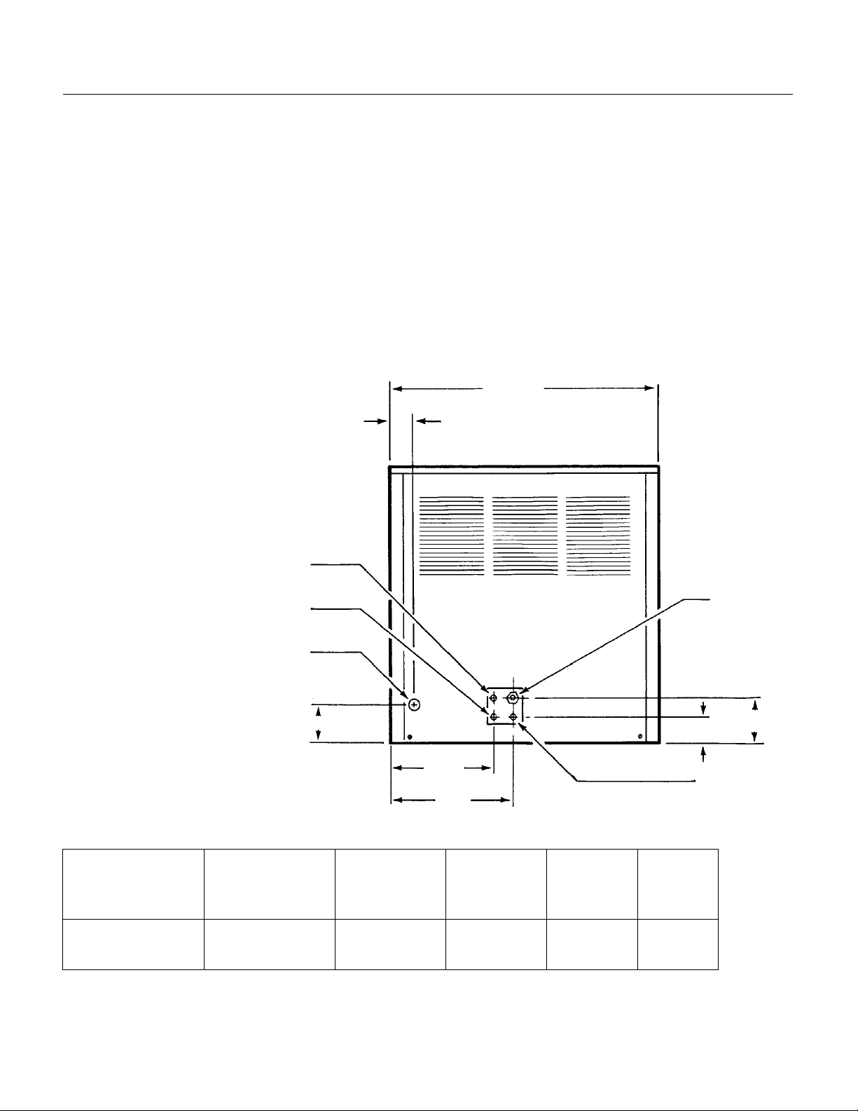
Drain 7/16" I.D.
Hose
12.7
11.4
Minimum
Circuit
Ampacity+
MF400
FOR THE INSTALLER
The MF400 is desig n ed to fit th e fo llowin g
Scotsman storage bins.
BH550 with bin top KBT20
HTB500 with bin top KBT2 0
The normal fin ish for th e mach in e is enamel
sandalwo o d. An op tio n al st ain le ss steel pan el kit
(SPKMF40 0A ) may be ord e red an d field installed
to convert the unit to a sta inless steel finish.
When installing the new system, check that
everythin g nee de d is on site :
Correct Ice Ma ch ine (v olt a ge
and type)
Correct Bin
Correct Bin Top
Legs for the bin
1 -7/16"
SPECIFICA TIONS :
21"
Condenser Drain 3/8"
O.D. Tube (Water Cooled)
Condenser Inlet, 3/8" O.D.
Tube (Water Cooled)
ICEMAKER
Electrical
Note: This servic e manua l is
for the current MF400 "B"
model, but applies in general
to the prior "A" model. The
primary differe nc es are in
the evaporator, spout and
the ice chute.
Model
Number
MF400AE-1B
MF400WE-1B
Dimensions
(w/o Bin)
H" x W" x D"
21.5 x 21 x 22
Inlet
same
2.5"
Basic
Electrical
115/60/1
same
8"
9.5"
Condenser
Type
Water
Air
Water Inlet
1/4" Male Flare
3.5"
2"
Maximum
Fuse Size
15
15
*Minimum Circuit Ampa cit y is used to dete rmine
wire size and typ e pe r Na tio n al Ele ct ric Co d e.
May, 1991
Page 2
Page 3
FOR THE INSTALLER
MF400
Installation Limitations:
This ice system is designed to be installed indoors,
in a controlled environment:
Min Max
Air Temperatu re 500F. 1000F.
Water Temperature 40
Water Pre ssure 20 psi 80 psi
Voltage -10% +10%
(Compared to the Na mep la te )
Operating the machine outside of the limitations is
misuse and can void the warranty.
Scotsman Ice Systems are designed and
manufac tu red with the h igh e st rega rd for sa fe ty
and performance. They meed or exceed the
standards of UL, NSF, and CSA.
Scotsman assu me s no liability or respo ns ibilit y of
any kind for products manufactured by Scot sm an
that have been altered in any way, including the
use of any part and/or other components not
specifically approved by
Scotsman.
Scotsman res erves th e r ight
to make design changes
and/or impro vements at any
time. Specifications and
design changes are subject to
change without notice.
0
F. 1000F.
Water Limitations:
An ice machine is a food manufacturing plant; it
takes in a raw mat eria l, wa te r, and tu rns it in to a
food product, ice. The purity of the water is very
important in obtainin g pure ice and in maximizin g
product life . This se ctio n is not int e nde d as a
complete resource for water questions, but it does
offer these ge nera l reco mmendatio n s:
1. Filter the wat er u sed to make ice. That is the
water going to the “potable” water connection.
Water filters vary gre a tly in ability a nd fu n ctio n .
Install one that filters out suspended solids to a
dimension of 5 microns or smaller. The finer the
filter the bette r, but fin e r filte rs will clog soon er tha t
course ones. It may be necessary to add a course
filter ahead of the fine filter to prolong filter life.
2. Check with a water treat men t spe cia list for a
water test, and recommendations regarding filters
and t r eatm ent .
Service Limitations:
There must be space above,
to at least one side, to the
back, and of course the front
for service access.
May, 1991
Page 3
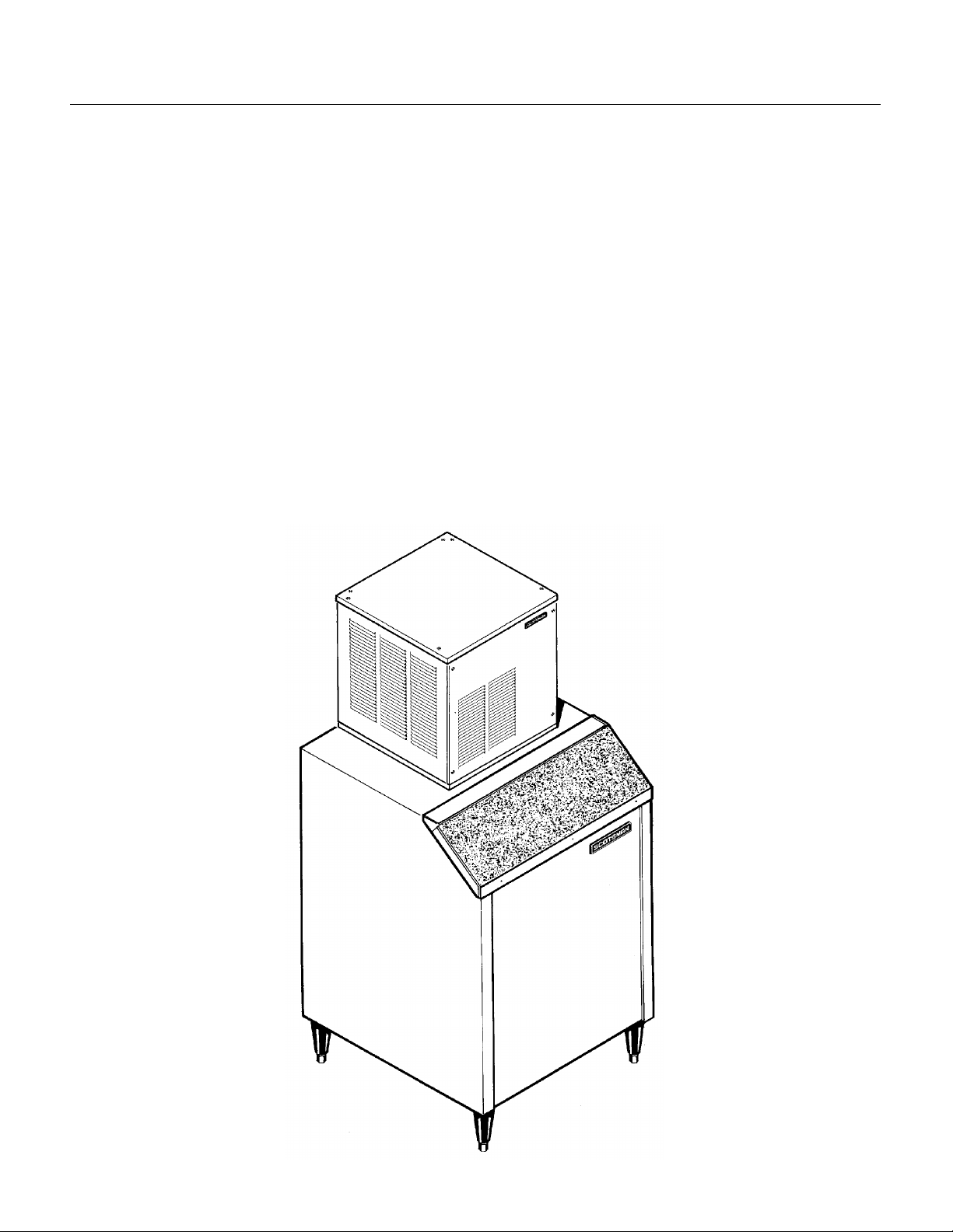
Page 4

ASSEMBLED VIEW
ICE CHUTE
ICE CHUTE INSTALLATION
MF400
FOR THE INSTALLER
Location
After uncrating and inspection, the unit is ready to
be installed.
It is important that the machine be installed in a
location where it has enough space around it for
service, and a minimum o f 6" be allo we d all sides
for air circulation. The machine, when air cooled,
draws air in the front, and exhausts it out the sides
and back.
Try to avoid hot, dirty and crowded locations. Be
sure that the location for the machine is within the
limitations described on page 3.
Storage Bin
Tip the uncrated storage bin on its back, using
parts of the carton to protect the exterior finish.
Install t he legs into th e th re ad ed ho les in th e
bottom of th e bin. Turn the leg levelers all the
way in preparatio n fo r le veling lat e r.
Return the bin to the upright position, remove
paper covering the bin gasket.
Install bin top if required.
Note: Do no t push bin int o position: but lif t it
there. Push ing a bin, espe cia lly one with ice in it,
can cause damage to the legs and the leg
mounts.
Ice Maker
The machine is heavy, so the use of a
mechanica l lif t is recommended fo r lif ting the
machine high eno ugh to install on top of the bin.
After the machine is placed on the bin, line it up
so that the ice discharge opening in the base of
the machine is over the open hole in the bin top.
Ice Chute Installation
After the MF400B has been installed on the ice
storag e bin, th e ice chut e n eed s to be inst a lled :
1. With the top panel of f, remo ve all pa ckin g
material (bub ble p ac k) from ab ove the ice chut e
and chute cap. Cut the ty-wrap holding the chute
assembly in place.
2. Remove the insula tio n halve s and ty-wrap
packed inside the cabinet, retain for later use.
3. Remove th e cardboa rd su p port fro m un d er th e
ice chute.
4. Insert the ice chute/bin thermostat assembly into
the large hole in the bottom of the ice machine.
Check that bin thermostat cap tube is free from
contact wit h most components.
5. Remove the rubb er ca p from th e to p of th e ice
chute. L eave one hose clamp on th e chu te .
6. Push the ice chute against the stainless spout
(the end of the spou t will go into th e chute ).
7. Slide the rub b er ca p ove r the to p of the sta inle ss
spout. Push do wn until it fit s tig h tly a round the
spout.
8. Secure the rubber cap to the spout with the two
hose clamps, in the molded grooves; one above
and one below. Keep hose clamp screws away
from evaporator.
9. Attach the insulation halves around the top of
the evapor ator. Secure with the ty-wrap provided.
Finish installation per service manual.
MOLDED
GROVES
RUBBER
CAP
HOSE CLAMP
RUBBER CAP
HOSE CLAMP
METAL ICE
SPOUT
HOSE
CLAMP
METAL SPOUT
HOSE CLAMP
May, 1991
Page 4
Page 5
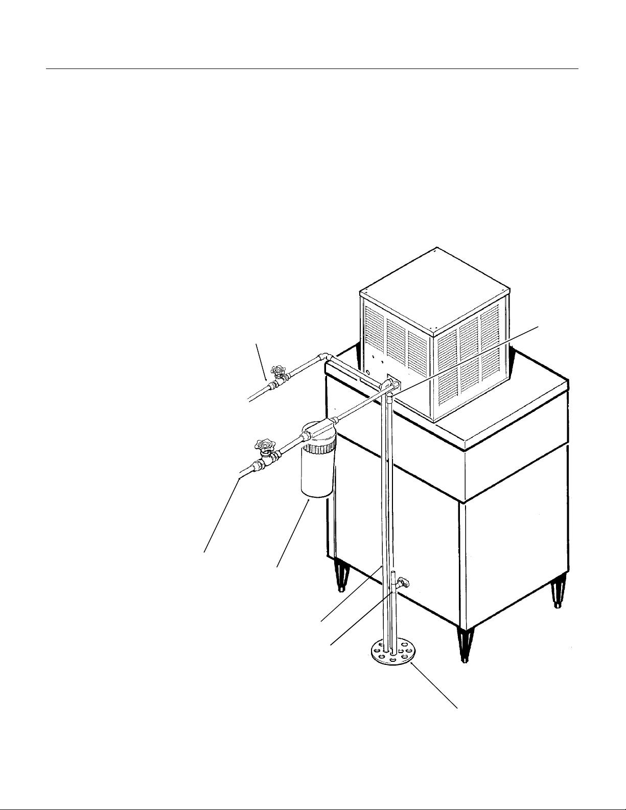
FOR THE PLUMBER
CONFORM TO ALL APPLICABLE CODES
Water Inlet
Air Cooled: The reco mme n ded wat er su pply is co ld
water. Use
1
⁄4" male flare a t the back of the ca binet. Install a
hand valve near the machine to control the water
supply.
Water Cooled: A separa te
should be connected to the condenser inlet, with a
separa te ha n d valve to c ont ro l it.
Drai n s
Air cooled: There is one 7⁄16" I.D.
hose to co nne ct to fo r a dra in. This
drain is a gravity drain, and a
minimum of 1⁄4" per foot fall is need ed
for horizontal portions of t he drain
line.
The ideal drain receptacle is a
trapped and vented floor drain.
Use only rigid tubing.
Water Cooled Models: In addition
to the above mentioned drain,
separate condenser drain must be
install e d . Connect to the
condenser drain tube.
Storage Bin: A separate gravi ty ty pe
drain needs to be run. This drain line
should be insulated.
1
⁄4" O.D. copper tubing, connect to the
3
⁄8" O.D. copper tube
CONDENSER
WATER INL ET
(Water Cooled)
3
⁄8"
MF400
OVERFLOW
DRAIN
POTABLE WAT ER
INLET
WATER FILTER
(FIELD SUPPLIED)
CONDENSER DRAIN
(Water Cooled)
BIN DRAIN
FLOOR
DRAIN GRIL L
May, 1991
Page 5
Page 6

MF400
FOR THE ELECTRICIAN
CONFORM TO ALL APPLICABLE CODES
The electrica l po we r to the unit is t o be wired
through the cabinet to the control box. In the
control box, connect to the t erminal strip provided.
Check the nameplate (located on the back of the
cabine t ) fo r th e vo lta g e requ irements, and for the
minimum circuit ampa cit y. The mach in e requ ires a
solid chassis to eart h ground wire.
The icemaker should be connected to it’s own
electrica l ci rcuit so tha t it is ind ivid u ally f u se d.
Voltage variation must remain within design
limitations, even under starting conditions.
All external wiring mus t co nfo rm to nat ion a l, st at e,
and local electrical co des. The use of e licensed
electrician is req uired to perf o rm the ele ct rical
installa tion.
ELECTRICAL POWER
SUPPLY
CONNECT ELECTRICAL
POWER TO ICEMAKER
THROUGH ELECTRICAL
INLET HOLE AND INTO
CONTRO L BOX
May, 1991
Page 6
Page 7

FOR THE INSTALLER: Final Check List
1. Is the ice syste m installed indoors in a loc at io n
where the air and water temperatures are
controlled, and where they do not e xceed the
design limita tio n s?
2. Is there an elec trica l servic e d isco nne ct with in
sight of the installed machine?
3. Have all the plumbing connections been made
and checked for leaks?
4. Has the machine and bin been leveled?
5. Is there a minimum of 6" clearance around the
machine for p rope r se rvice and air ci rcula t ion ?
6. Is the water pre ssure a minimum of 20 psig?
7. Has the ice disch arge tube been installed ?
8. Is there a wate r s hut off inst a lled ne a r the
machine?
9. Have all shipping materials been removed?
Electrical
Power?
MF400
Water Supply?
Leveled?
Drains?
May, 1991
Page 7
Page 8

MF400
START UP
1. Remove scre ws a nd the fro nt pan el.
2. Open the water shut off valve.
3. Observe that the water flows into the water
reservoir, fills up the wat e r in let tu be to th e
evapora to r, the floa t move s up with the wa te r leve l,
and the float shuts off the water flow, about
below the mold ed horizo n ta l line on th e wate r
reservoir.
4. Switch on the ele ct rica l po wer to th e unit .
5. Switch the master switch to ON.
6. After a few minutes of operation: water should
begin to flow fro m th e res ervo ir to the ev apo rat o r;
the air cooled c ond enser sh ou ld begin to di s charge
warm air, or the water cooled condenser should
begi nning to di s charge warm water ; and the un it
should begin to drop ice into the storage bin.
If desired, the refrigeration pressures can be
checke d :
••The air cooled dis charge pressu re should be
about 125-135 PSIG and the suction pressure
should be abo u t 12-1 5 PSIG.
••The wate r coo le d d isch a rge pre ssu re sh o uld be
set at 135 PSIG.
••Gearmotor amps shou ld b e abou t 2.8 - 3.2.
••Compressor amps should be about 8.5 - 9.
7. Let the unit operate for 15-30 minutes, checking
for water leaks , or ex ce ssive noise from vibra tin g
compon e n ts.
8. Block off the ice disch a rge tu b e, and che ck if th e
bin thermostat shu ts off the mac hin e. Afte r it shut s
off the compressor, the auger moto r sho uld ru n fo r
a few minutes more. Allow the ice in the tube to fall
away, and check that the compressor restarts.
9. Explain the op eration and maintena n ce
requiremen ts to the use r, in fo rm the us er of the
telephone number of the service agency servicing
the machine, and give the user the service manual.
3
⁄8"
May, 1991
Page 8
Page 9

COMPONENT LOCATION: Control Box
Auger Delay Pressure Control: This pressure
switch, connect ed to th e low side of the
refrigeration system, controls the auger drive
motor.
Low Pressure Control: This pressu re switc h,
connect e d to th e low side of th e ref rige ration
system, is normally clos ed when the mach ine is
operatin g . If the low sid e pres su re sh ou ld dro p too
low, the contro l will open (at 0 -4 PSIG ), stop pin g
the ice maker. It is an automatic reset.
High Pressure Control: The
pressure switch, used on water
cooled models only, is designed
to open and shut off the machine
should the high side refrigeration
pres sure become too high,
usually as a result of not enough
water through the water cooled
condenser.
It is a manual reset.
On-Off switch: This toggle
switch shuts off the mach ine. It is
not a complete disconnect.
Bin Thermostat: This
thermostat turn s th e mach ine on
and off in response to chan ges in
temperature of the capillary t ube.
It opens at 35
0
F. The capillary tube is
45
mounted on the inside of the ice
chute.
0
F. and closes at
Low Pressure
Control
MF400
Auger Delay Control
Bin Thermostat
On-O ff Switch
May, 1991
Page 9
Page 10

MF400
ELECTRICAL SEQUENCE
There are two circu its in the MF4 00: one is a
series circuit with several switches connected in
series to the compre sso r. The ot h er is a para llel
branch of the series circuit, controlling the gear
driv e m otor.
••The series circuit begins at the termin a l strip in
the control b ox . F rom the re, the line sid e p owe r
is connecte d to th e Mast er Swit ch .
••When the master switch is closed, the power is
then connected to the Spout Switch. This
switch, located on the top of the ice chute , is
closed unless the ice chute has overfilled with
ice, it is an automatic reset.
••From the spout swit ch the line sid e powe r now
is connected to the Low Pressure Control (air
cooled) or the High Pressure Control and then
the Low Pre ssu re Co nt rol (wat e r coo led ). Th es e
controls, connected to the refrigeration system,
are design e d to ope n whe nev er higher (high
pressure co nt rol) pressures or lower (low
pressure c ontrol) pressures are sensed. The
high pressure control is a manual reset, the low
pressure co nt rol is an aut omatic reset.
••The line side power is also co nn ect ed , in a
parallel ci rcuit , to terminal 1 of the Auge r Dela y
pressure co nt rol. This pressure control,
connected to the low side of the refrigeration
system, is desig ned as a by-pa ss circu it to the
auger drive motor whenever the low side
refrigera n t pressure is at it’s normal ice making
range. At start up, the contacts between
terminals 1 an d 2 are op e n. The lin e side power
does not pass any further through the auger
delay pressure control, until t he compressor
starts, and the low side pressure drops.
••The next control the power is conne ct ed to is
the Low Water Pre ssure Control. This switch is
designed to open should the water press ure to
the machine drop too low.
••The next control is the Bin Thermo st at . It is
closed when there is no ice on the portion of the
control inside the ice chute. It is open when
there is ice on the portion of the control inside
the ice chu te . Clo sin g of th e bin th ermo stat
begins the process of making ice, because the
line side power now goes to the compressor,
gearmotor, a nd if air co ole d, the fa n moto r.
••Power is initia lly co nne cted to th e gearmo tor
through contacts 3 and 2 of the auger delay
pressure co nt rol. This ca u ses th e aug er mo tor
to start and run. At the same time, if the
centrifuga l switch on to p of the ge a rmo t or
closes (mea n in g the mo tor is a t full sp e ed) t he
compressor is connected to the neutral side of
the powe r sup p ly, and th e comp res sor begin s to
run.
••As the co mpre ssor run s, th e low sid e or su ct ion
pressure begins to fall, when it reaches a preset
point, the contacts within it move, opening 3 and
2, then closing 1 a nd 2. The power for the
gearmotor is then connected to a point in the
series circuit ahe ad of the lo w pres su re co nt rol,
the low water p res su re co nt rol and the bin
thermostat, so that if any of these open, the
gearmotor will con tin u e to run, pus hin g ice out
of the evaporator .
May, 1991
Page 10
Page 11

OPERATION: Water
SAFETY
SWITCH
Water enters the machine through the 1/4" male
flare at the rear of the cabinet, goes past the water
pressure switch and th en to th e wate r rese rv oir
which it enter s through the float valve. The water
then goes out the bottom of the reservoir tank to
the bottom of the evaporato r .
Reservoir ov erf lowis rout e d to the drain . Water
cooled mode ls ha ve a sep arate wat e r circu it fo r th e
cooling water: it enters the fitting at the rea r, g oes
to th e water regul ating val v e, then to th e wa ter
cooled condenser and down the drain.
WATER RESERVOIR -
FLOAT VALVE
PRESSURE
SWITCH
MF400
WATER SEAL
SPOUT
WATER
INLET
RESERVOIR
OVERFLOW
ICE
CHUTE
DRAIN
AUGER DRIVE
MOTOR
ICE AND WATER SCHEMAT I C
"B" MODEL
May, 1991
Page 11
BIN
THERMOSTAT
BRACKET
Page 12

CONDENSER
MF400
OPERATION: Refrigeration
Beginnin g at the co mpre ssor, the refrig e ran t is
compressed into a high temperature gas. The
discharge line directs this gas to the condenser. At
the condenser (air or water cooled) the gas is
cool ed by either air or water and it then condenses
into a liquid. This high pressure liqu id then go e s
through the liq uid line to the cap illary tu be . The
capillary tube meters liquid refrigerant into th e
evaporator, the volume of liquid refrigerant
depending upon the temperature of the evaporator;
warmer evaporators get more refrigerant and
colder ev apo rat o rs get les s.
At the evaporator, th e refrig era n t ent ers a n area of
relative ly low pre ssu re , whe re it can easily “bo il of f”
or evaporate. As it evaporates, it absorbs heat
from the evaporator and whatever is in contact with
it (such as the water inside it). After the evaporator,
the refrigerant, now a low pressure vapor, goes
through the su ct ion line back to compress or, whe re
the cycle is repeated.
COMPRESSOR
EVAPORATOR
ACCUMULATOR
CAPILL A RY TUB E
DRYER
May, 1991
Page 12
Page 13

MF400
MAINTENANCE AND CLEANING
/////////////////////////////////////////////////////////////////////////// //////////////////////// //////////////////////// ///////////////////////////////
A Scotsman Ice System represents a sizable investment of time and money in any company’s
business. In order to recei ve the best return for that investment, it MUST receive periodic
maintenance.
It is the USER’S RESPONSIBILITY to see that the unit is properly maintained. It is always
preferable, and less costly in the long run, to avoid possible down time by keeping it clean;
adjusting it as needed; and by replacin g worn part s before they can cause failure. The follo wing
is a list of recommended maintenance that will help keep the machine runn ing with a minimu m of
probl ems.
Maintenance and Cleaning should be scheduled at a min imum of twice per year.
///////////////////////////////////////////////////////////////////////////////////////////////////////////////////////////////////////////////////////////
//////////////// // //// //// // /WARNING//////////////////////// // /
Electrical power will be ON when doing in
place cleaning.
Switch it OFF before
completing the cleaning procedures.
///////////////////////////////////////////////////////////////////////////
ICEMAKING SYSTEM: In place cleaning
1. Check and cle an a ny water t rea t men t de vice s, if
any are installed.
2. Remove scre ws an d remov e the top and front
panels.
3. Move the ON-OFF switch to OFF.
4. Open the door to the ice storage bin, and
remove the ice.
5. Remove th e cove r to the wat e r res ervo ir a n d
block the float up.
6. Drain the wa ter re serv oir and free ze r ass embly.
//////////////// //////// ///W ARNING //// //////// //////// /////////
Scotsman Ice Machine Cleaner contains
Phosphoric and Hydroxyacetic acids. These
compounds are corrosive and may cause
burns. If swallowed, DO NOT induce
vomiting. Give large amounts of water or
milk. Call Physician immediately. In case of
external contact, flush with water. KEEP OUT
OF THE REACH OF CHILDREN.
//////////////////////////////////////////////////////////////////////////
7. Prepare the cleaning solution: Mix eight ounces
of Scotsma n Ic e Ma ch ine Cleaner with three
quar ts of hot w ater. The w ater should be between
90-115 degrees F.
8. Slowly pour the cleanin g solution into the water
reservoir un til it is full. Wait 1 5 minut e s, the n
switch the master switch to ON.
9. As the ice maker begins to use water from the
reservoir, co n tin u e to add more clea ning solution
to maintain a full rese rvoir.
10. After all of the cleaning solution has been
added to the reservoir, and the reservoir is nearly
empty, switch the master switch to OFF.
11. After draining the reservoir, as in step 6, wash
and r inse the water reservoir.
12. Remov e the block from the float in the water
reservoir.
13. Switch the maste r switch to ON
14. Contin u e ice making for at least 15 minu t es , to
flush out any cleaning solution. Check ice for acid
taste - continue icemaking until ice tastes sweet.
/
/////////////////////////////WARNING//////////////////////////
DO NOT USE any ice produced from the
cleaning solution.
Be sure no ice remains in the bin.
//////////////////////////////////////////////////////////////////////////
15. Remove all ice from the storage bin.
16. Add warm water to the ice storage bin and
thoroughly wash and rinse all surfaces within the
bin.
17. Sanitize the bin interior with an app rove d
sanitizer using th e di rect io ns for tha t sa nit ize r.
18. Replace the top and the front panels.
May, 1991
Page 13
Page 14

MF400
MAINTENANCE AND CLEANING
///////////////////////////WARNING////////////////// ///////////
Disconnect electrical power and shut off the
water before beginning.
//////////////////////////////////////////////////////////////////////////
In some areas, the water supply to the ice maker
will contain a high conc ent ration of mine rals , and
that will result in an evaporator and auger
becoming coat ed with th ese min era ls, requirin g a
more freque n t remo va l th an twice per year. If in
doubt abou t the cond itio n of the evap o rat o r and
auger, the auger can be removed so the parts can
be insp ected.
Note: Wate r filt e rs can filte r ou t su sp e nde d solid s,
but not disso lve d solid s. “Sof t” wat er may not be
the complete answer. Check with a water
treatmen t sp ecialist regarding water treatment.
For more information on removal of these
parts, see REMOVAL AND REPLACEMENT.
To Inspect The Top Bearing:
1. Remove perma gum and two screws fro m th e
side of the evaporator .
2. Remove the sna p ring and ca p, and remov e the
bolt from the ice bre ake r an d auge r asse mb ly to
separate th e ice bre a ke r asse mbly from the au ger.
Pull the ice bre ake r with bea ring out of the to p of
the evaporator: the auger should stay in the
evaporator.
The bearings may be inspected for rust, wear, and
roughne ss. Reverse to reassemb le.
To Inspect the Auger:
1. Remove perma gum and two screws fro m th e
side of the evaporator .
2. Pull up on cap hook located in the top of the
freezer assembly to remove the ice breaker
assembly, a ug er, an d th e top portio n of the wat er
seal.
3. Inspect the auger and the water seal. Clean the
auger of any mineral build up. Scotsman Ice
Machine Clea n e r and a sco u ring pa d wo rk well to
clean the auger. DO NOT USE steel wool.
//////////////// // //// //// /WAR N ING//////////////////// // //// ///
Scotsman Ice Machine Cleaner contains
Phosphoric and Hydroxyacetic acids. These
compounds are corrosive and may cause
burns. If swallowed, DO NOT induce
vomiting. Give large amounts of water or
milk. Call Physician immediately. In case of
external contact, flush with water. KEEP OUT
OF THE REACH OF CHILDREN.
//////////////////////////////////////////////////////////////////////////
4. Replace th e wa ter sea l, se e the ins tructions
under "Removal and Replacement".
TOP
BEARING
AUGER
May, 1991
Page 14
Page 15

SERVICE DIAGNOSIS: Condition - No Ice Being Produced
MF400
STATUS:
A. Check: Vo ltage to the unit, restore it if there is none. Compare to the nameplate.
B. Check: The master switch, switch ON if off .
C. Check: The 3 reset switches, (circuit board, high and low pressure): depress and release eac h switch.
If the still does not sta rt, check : th e spo ut switc h; the high an d th e low side pre ssu res .
D. Check the low pressure cut out, if closed, go to E; if it is open, it could be due to:
ICE MAKER DOES NOT OPERATE
••Low refrigerant cha rg e
••The auge r no t tu rnin g
••Restrict ed sys tem
1. Check the low side pressure, the low pressure cut out o pens at pressure below 4 psig.
If open, reset and:
a. Check if the
Check for internal damage, repair and replace in the machine.
b. Check for low charg e , add some ref rig e rant , if th e un it will op erate , (no rmal
low side pressure being about 13 psig) stop and look for a leak, repair, rep lace the
drier, evac uat e, an d weig h in the nameplate charge. If, with a dde d cha rge , the un it
not operate:
does
Check for a restrict ed syst e m, rep la ce the drie r, ev ac uat e, and weig h in a
nameplate charge.
D. On Wa t er Coo led, check th e high pressure cut out, if closed, go to E; if open:
1.The pressure control opens at 250 psig. Chec k the hig h side pre ssure, reset the control,
and observe: that wate r soo n beg ins to flow fro m the co nd en se r d rain ;
If the unit trips out on
pressure s be lo w 2 50 p sig , rep la ce the co nt rol.
poi nt, and the u nit shuts down:
a. Check for adequate water flow on through the condenser, if adequate, clean the interior
of the conden se r. If the pre ssu res are st ill to o high rep la ce the wat e r reg ulating valve.
E. Check the spout switch. It opens from excess pressure of ice inside the ice chute: this should only
happen when the machine does not shut off when the ice storage bin is full. This switch will reset when the
ice melts,
F. Check the water pressure to the unit. The machine will not run if the re is no t e nou gh wa te r pres su re.
1. Restore/adjust water supply.
auger is tu rnin g , if it is not, remo ve the gearbox and :
If the pressure s rise abo ve the trip out
May, 1991
Page 15
Page 16

MF400
SERVICE DIAGNOSIS: Condition - No Ice Being Produced
STA T US:
H. Check: Th e g ear motor , if it will not run, the compressor will no t run. If no powe r to it:
Check that the Bin The rmo stat is close d . If open, with no ice on it, repla ce the bin the rmos ta t.
Check th at th e Aug e r De lay con ta ct s 3-2 are close d . If ope n, and the low sid e (suct ion) pre ssu re is ov er 32
PSIG, repla ce th e aug er d elay pressu re co ntrol.
If power to the auge r drive mot or, an d it does n ot ru n, rep la ce the aug e r drive mo to r.
STATUS:
A. Check the au ge r drive moto r cen trifugal switch. If, when the d riv e moto r is runn in g,
the compressor has no power, and all of the above switches have been
checked, rep lac e the cent rif ugal switch.
B. Check the compressor
1. Check the compressor start relay.
2. Check the start capacitor.
3. Check the windings of the compressor for open windings or shorts to ground.
Replace those items found defective.
ICE MAKER DOES NOT OPERATE
GEARMOTOR OPERATES, COMPRESSOR DOES NOT
May, 1991
Page 16
Page 17

REMOVAL AND REPLACEMENT
MF400
Ice Breaker and Auger Removal
1. Remove perma gum and two screws fro m th e
side of the evaporator .
2. Pull up on cap hook located in the top of the
freezer assembly to remove the ice breaker
assembly, a ug er, an d th e top portio n of the wat er
seal.
3. Remove the sna p ring and ca p, and remov e the
bolt from the ice bre ake r an d auge r asse mb ly to
separate th e ice bre a ke r asse mbly from the au ger.
The bearings may be replace or the ice breaker
and bearing s may be rep laced as an asse mbly.
Water Seal Installation
Inspe ct the water seal in
it’s package. Do no us e if
mating surfaces are
scratched or cracked.
1. Remove aug e r, unb olt
evaporator from adaptor
stand. Drive out old
bottom bea ring an d wat er
seal from the top down.
2. Remove th e old rota ting
half of the water seal from
the auger and clean the
auger at the seal
mounting area.
Outer Race
Sealant Here
Rubber
Metal
Water
Seal
3. Apply Scotsman part number 19-0529-01 food
grade sealan t to the auger shou lder before
pushing on the water seal. Place just enough
sealant onto the shoul der of the auger , so that
when the water seal is placed on the auger, the
gap between the auger shoulder and the water
seal is complet e ly fille d with th e seala nt.
4. Clean th e in sid e of th e eva p ora to r at the bot to m
bearing and wat e r seal mou nt in g area. L ubrica te
the outsid e e dge of the stationary seal with water.
5. Carefully p us h the sta tio n a ry part of the wat e r
seal up into the bot tom of the evaporator. It m ust
go in straigh t and mus t not be push ed in b ey ond
1/4" past the bottom of the evaporator.
6. Install a new bottom
bearing , push it int o the
evaporator unde r the new
water seal. It must be pushed
in straight, but do not push it in
past 1/8" from the bottom of
the evaporator tube.
7. Mount the adaptor stand to
the bottom of the evaporator.
Wider at Top
Han d tighten th e th r ee cap
screws until the stand flange is
tight against the bottom of the
evaporator. Hand tighten the
three cap screws until the
stand flange is tight against
the bottom bearing . Then,
tighten the screws in a rota ting
pattern to insure proper
alignment.
8. The top be a ring should also
be changed at this time. Be
sure to mount the top
breaker/bearing assembly
onto the auger before
installing the auger into the
evaporator tube.
9. Lower the auger into the
evaporat or, twist it to en ga ge
the splines of the coupling.
Secur e the breaker and
bearing to the evapora tor tube
with the two screws removed
in step 1 of “Ice Breaker an d
Auger Remova l”. Tes t the unit.
May, 1991
Page 17
Page 18

MF400
REMOVAL AND REPLACEMENT: Gearmotor Assembly
Rebuilding The Gearmotor Assembly
Drive Motor Parts:
To replace the cen trifugal switch and mechanism
or the motor winding or the motor roto r, re mo va l of
the gearbox as se mbly is not nece ssa ry.
1. Disconnect elect rical p ower.
2. Remove th e cove r f rom the to p of th e cen trifugal
switch assembly and remove the electric wires
from the microswitch. To replace just the
centrifugal switch , remo ve two machine screws
retaining th e switch , and remo ve the switc h. To
replace , reverse the procedure to th is point.
3. If the motor is to be removed, the next step is to
remove the four screws holding down the plastic
switch assemb ly housing and lift the housing of f of
the motor top.
4. Remove the cen trifugal switch mechanism fro m
the rotor by uns crewin g the ma ch ine scre w at th e
top of the rotor.
5. The motor and housing may now be removed.
Lift off the motor fan housing, and pull off the
plastic fan . Th e nex t part to be re mo ve d is the
motor winding . Disconn ect th e elect ric al le ads o f
the motor from its control box location and lift off
the winding .
6. The rotor is all that remains of the motor in the
gear motor asse mbly . Use a pry bar to carefu lly
pry up the rotor. (The only thing holding it in is the
tight fit of the bottom rotor bearing into the top of
the gear case.) To replace any of the above parts,
reverse th e disa sse mb ly procedure.
Removal of the Gearmotor Assembly
1. Remove the top and righ t side pan el.
2. Remove the ice ch ut e asse mb ly.
3. Unscrew the th ree cap scre ws reta in in g the
evaporator assembly to the gearmotor assembly.
4. Unscrew the bolts holdin g the gearmotor
mounting plate to the ice machine chassis.
5. Remove the motor and centrifugal switch
electrical leads from their connections.
6. Raise the evapo rator as se mbly up enoug h that
the output shaft clears the freezer adaptor.
7. Remove the gearmo to r ass embly from the ice
machine.
Gearcase Service
After removal of the gear motor from the unit ,
inspect the inte rn al parts from this g earmo to r.
1. Place the gearbox on a flat surface, covered
with rags to absorb a ny spilled lub rican t .
2. Using a punch, drive the roll pins out of the
casing.
3. Remove the four c ap scre ws on th e top of the
gearcase and the two under the motor.
4. Pry the two case s apa rt.
When inspecting the internal parts, look for:
••Condition and quantity of lubricant. (The proper
oil level is near the top of the output (biggest)
gear. This ta ke s 5 oz. Use Sco ts man oil, pa rt
number A25835-001.
••Bearing condition
••Gear and Shaft condition
••Woodruff key between output gear and shaft.
••Grease seals, back to back.
••Vent hole
Be sure to count and retain the spacer washers as
they come out of the gearbox.
Replace the parts as required, using the part
numbers found in the parts section of this manual.
Replace th e gears into a CLE AN b ot to m ge a rca se ,
after adding some grease to the bearings. Replace
the spacers in th e same qua n tit y as th e y were
removed. If no cou nt wa s kep t , use the numbers
found in the parts list.
Note: Some bearing grease should be placed in all
bearings before assembly to insure proper
lubricat ion upo n sta rt up .
Reass em b l y
1. Set top gearcase on gears and spacers and oil.
Be sure O-ring is in place .
2. Drive roll pins ba ck int o loca ting ho le s.
3. Replace cap scre ws int o gea rca se cov er, and
torque at 80-90 inch pounds.
4. Bench tes t the gearmo to r ass embly.
Test for noise, amp draw (must not be in excess of
ice maker nameplate for gearmotor) and oil leaks.
Return the ge armo t or asse mbly to the unit. Be
certain all mounting surfaces are clean and
reassemble to the gea rmotor mounting plate. Then
bolt back onto ice machine chassis.
May, 1991
Page 18
Page 19

Gearmotor Service
MF400
MOTOR COVER
WINDING
SHAFT SEALS
FAN
OUTPUT
SHAFT
ROTOR
KEY
FIRST GE AR
AND PINION
May, 1991
Page 19
 Loading...